1. Introduction
Fiber lasers find many applications in materials processing. Applications such as cutting, welding, drilling, and marking metal accounted for more than half of fiber laser sales. To maximize the penetration of fiber lasers in these and other market segments, it is necessary to increase their output power.
Conventional fiber lasers, in which the gain medium consists of a single-fused silica fiber, can emit only about 1.2 kW of power. This limit stems from the physical properties of rare-earth-doped silica fibers. Compared with amorphous silica fibers, the single-crystal yttrium aluminum garnet (YAG) fibers that we have developed offer much better physical properties to handle much higher output powers, enabling a whole new array of applications (materials processing, medical lasers, etc.).
There have been several approaches to the development of high-power (i.e., multi-kW) lasers. Bulk single crystals have been extensively used for their excellent thermal conductivity, efficiency and mechanical resistance. However, heat dissipation becomes a problem in these systems at very high powers. A good remedy is to use fibers instead of bulk crystals. Several kilowatts of CW (Continuous Wave) output power have been demonstrated in ytterbium-doped glass fiber, with excellent efficiency. In fiber lasers, the pump is guided in a medium that is about 100 µm in diameter and the laser signal is guided in a single-mode core (about 10 µm). The low absorption of the pump is spread over a long length of fiber (around 1 m), which makes the heat load better dissipated than in a bulk crystal, where the pump is absorbed over only a few millimeters. However, fiber lasers exhibit limited performance in pulsed regime because high peak powers confined in a small core induce nonlinear effects that affect the quality of the laser beam. Our solution is to develop single-crystal fibers that can act like a hybrid medium between glass fibers and bulk crystals.
All of the advantages of bulk single crystals—thermal conductivity, efficiency, mechanical resistance—are kept with single-crystal fibers.
For example, single-crystal fibers of yttrium aluminum garnet (YAG, Y
3Al
5O
12) provide a potential pathway to fiber lasers with higher output power. Compared with amorphous silica fibers, single-crystal YAG fibers offer higher thermal conductivity, higher Stimulated Brillouin Scattering (SBS) thresholds, higher melting temperature, and higher doping concentrations [
1], as well as excellent environmental stability.
Table 1 compares the thermal, physical, and optical properties of amorphous silica fibers and single-crystal YAG fibers [
2].
Equation (1) shows a formal expression for the power limit of a fiber laser due to SBS and thermal lensing [
3]
where
λ is the laser wavelength,
G is the gain,
ηLaser is the optical-to-optical efficiency,
ηheat is the fraction of the pump power converted to heat, Γ is the mode field-core overlap,
dn/
dT is the refractive index change of core with temperature,
k is the thermal conductivity, and
gB(Δ
ν) is the peak Brillouin gain coefficient. By substituting the values from
Table 1 into Equation (1), we find that the power limit of a laser with a single-crystal YAG fiber gain medium is about 50 times higher than that of a laser with an amorphous silica fiber gain medium. They can absorb less at longer wavelengths and generate, in theory, 50 times more power than a silica fiber laser.
The most prominent recent trend in fiber laser technology aiming at major power scaling out of a single laser aperture is transitioning from all-glass double- and triple-clad fibers to fully crystalline double- and triple-clad fibers. It has been perceived lately as a major next step in fiber laser development, with the projected advancement in power scaling with diffraction limited beam quality by at least an order of magnitude out of single-fiber aperture [
3,
4]. A few demonstrations toward that end, based on fully crystalline, relatively short, square cross-section, fiber-like waveguiding structures fabricated using the adhesive-free bonding (AFB) technique [
5], provided a sufficient basis for favouring fully crystalline structures versus conventional all-glass structures [
6,
7,
8]. Despite these demonstrations, the AFB-based fully crystalline double- and triple-clad fiber fabrication technique is deemed way too labour-intensive and, thus, not amenable for mass-producible fiber fabrication. In contrast to that, recent successes in producing high-quality, long and smooth, round crystalline fiber cores using the laser heated pedestal growth (LHPG) technique were recognized as promising for mass production (pending development of equally mass-producible crystalline cladding deposition technique). So far, quite impressive laser results with glass-clad doped crystalline YAG cores, grown by LHPG, were obtained (e.g., References [
9,
10]). Unfortunately, glass-clad double-clad fibers lack the required potential for power scaling due to the glass clad functioning, essentially, as a pretty thick thermal insulator around the crystalline core. To the best of our knowledge, the fully crystalline double-clad LHPG-grown fiber has not been reported as lasing (or amplifying) so far, namely due to major challenges in developing high optical quality crystalline cladding. Those challenges are not believed to be insurmountable, and quite a few efforts in developing techniques for high optical quality crystalline cladding deposition on the cylindrical circumference of LHPG-grown crystalline cores are ongoing (e.g., references [
11,
12]). Meanwhile, major improvement in optical quality of the LHPG-grown fiber cores themselves is still required. In the process of perfecting crystalline core fabrication via LHPG, in order to scale the fiber core length with the highest optical quality, the fiber quality assessment using just straight-through laser light propagation (representative of bulk material loss only) is no longer sufficient. Fiber core quality assessment should be complemented by experiments, which can be indicative of low waveguiding loss as well. In that sense, laser experiments utilizing crystalline fibers as gain medium can be adequate. Experiments with single-crystal fibers (SCF), as most often used in the literature today [
13], where the “SCF” term is referring to only relatively thin (under 1 mm diameter) and pretty short (30–60 mm long), air-clad single-crystalline gain element (rod), in a laser configuration where only the pump power is guided by the total internal reflection (TIR) of the cylindrical circumference, are not adequate for that. Indeed, in most reports on SCF lasers, the pump is flood-illuminating the volume of the gain medium, while the generated laser signal is in a free propagation mode inside the laser rod, so the laser mode structure is defined solely by the external cavity mirror configuration [
13,
14,
15]. This mode of laser operation does not involve waveguiding of the laser light and, thus, is not indicative of a waveguiding quality of the SCF core. Presented here are some experimental laser results obtained with the diode pumped at 969 nm, 100 μm diameter, 100 mm long, unclad Yb:YAG crystalline fiber, wherein both the pump light and the generated laser power are waveguided. To the best of our knowledge, the demonstrated laser operation is based on the thinnest and the longest unclad crystalline fiber reported so far. It is also believed to be the first true waveguided laser operation reported from an unclad single-crystalline fiber. Laser efficiency of over 58% obtained from the studied fiber, despite its use without the antireflective (AR) coatings on laser quality polished tips, is a manifestation of low composite loss figure, inclusive of both material bulk and waveguiding loss.
Another approach to generate high-power lasers is to amplify the power of existing fiber lasers. To achieve this, the use of thin (with diameters between 200 µm and 1 mm) Yb:YAG crystal rods (for amplification at 1 µm) is becoming more and more popular since it enables compact high-power amplification modules. The laser heated pedestal growth (LHPG) technology is uniquely suited for this application because is it very versatile and allows for growing thin rods in various shapes and with gradients of dopants.
2. Results
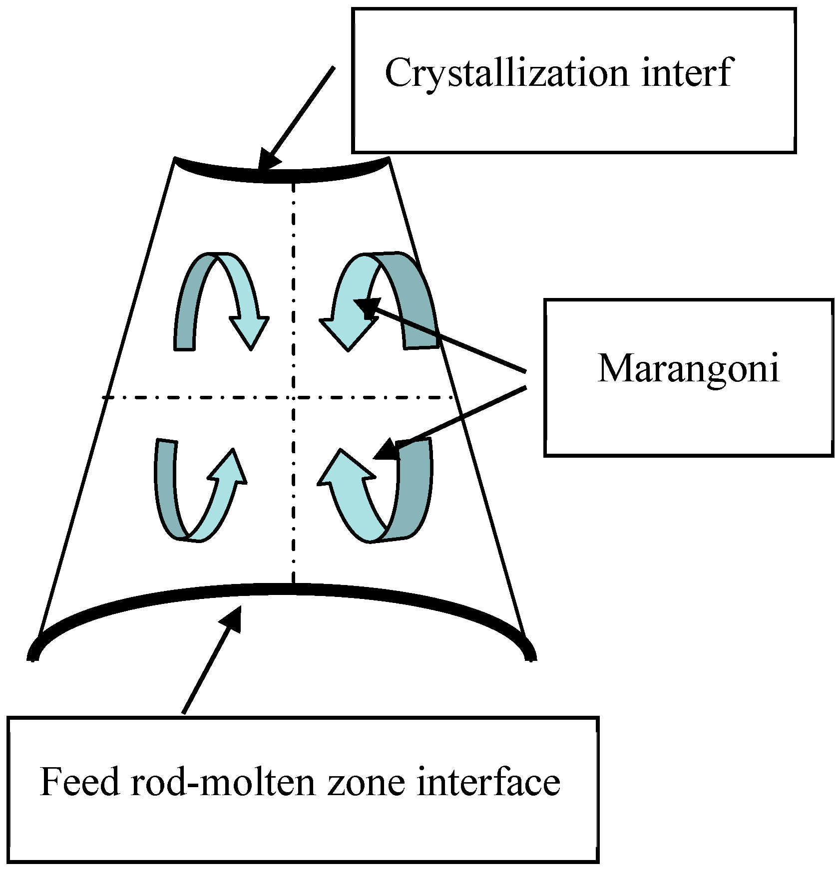
To fabricate single-crystal YAG fibers as laser gain media, the technical challenge is to synthesize a cladded flexible fiber with a core of dopant—such as Er, Nd, or Yb—that will exhibit good waveguiding properties. LHPG offers a competitive advantage over other techniques for growing single-crystals fibers for this application. The growing crystal accepts yttrium, aluminum, and oxygen in the garnet structure and rejects dopants with segregation coefficients different than 1. The temperature differences between the molten zone, the air, the crystal, and the feed rod create four convection cells in the molten zone. In all four cells, Marangoni convection currents drive the dopant impurities to the center, creating a natural core in Nd dopant (
Figure 1).
This statement is what the theory predicts for dopants with a large ionic radius like Nd and is not borne out with every dopant such as in the case of Er.
We can grow Nd:YAG fibers with a doped core and undoped YAG cladding fibers over 1 m in length. These fibers consist of a doped core 30 microns in diameter surrounded by an undoped YAG cladding with an outer diameter of 70 to 100 microns.
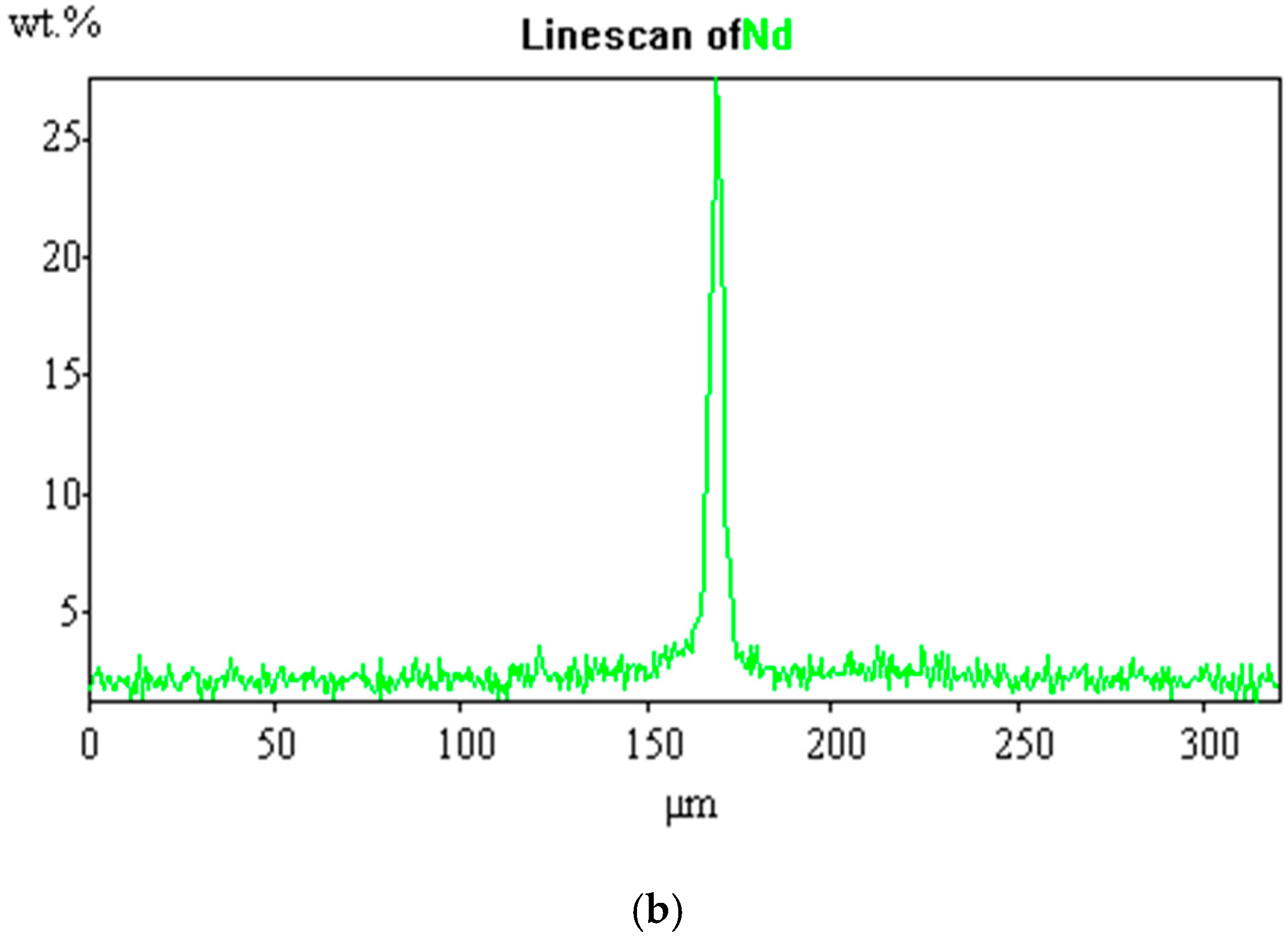
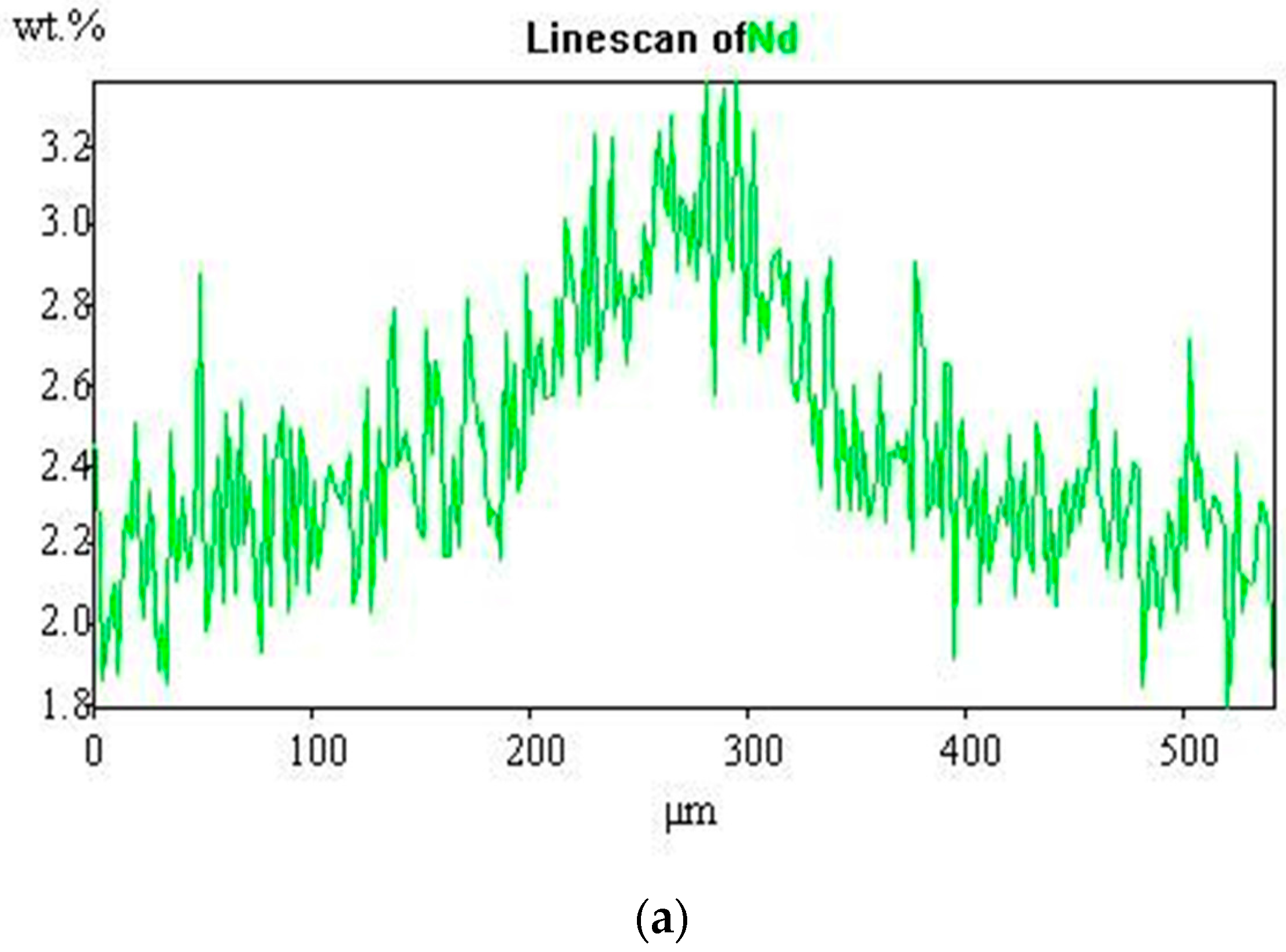
Electron dispersion spectroscopy (EDS) measurements revealed the Neodymium-doped core. We studied the dopant concentration profiles at both polished end faces of the fibers via EDS.
Figure 2a shows the distribution of neodymium atoms in a YAG fiber 100 mm long and 550 microns in diameter. A neodymium-doped core occupies 30% of the overall diameter of the crystal. Both end faces exhibited the same dopant concentration profile, indicating that the doped core occupies the entire length of the crystal.
We regrew the crystal three times. The 20 µm core could be achieved in one growth, if diameter is 60 µm, ratio of core to diameter of fiber is what changes with regrowths. The feed/pull ratios used was kept similar.
Figure 2b shows the distribution of Nd after the third regrowth. The diameter of the Nd-doped core shrunk to about 50 microns, or 1/7 of the total diameter. We observed the same dopant concentration profile at both end faces.
As-grown fibers satisfied the requirement for total internal reflection. We measured the refractive index of the Nd:YAG single-crystal fibers at UC Berkeley’s Marvell Nanofabrication Laboratory with Ellipsometer (Sopra–380, spot size of 75 µm × 150 µm). The higher core refractive index (~0.7%) achieved by adding dopant and a critical angle of 80.03° for total internal reflection indicates that the natural segregation of Nd ions in the core of the single-crystal Nd:YAG fibers creates a guiding structure. The fibers will require no further external cladding to serve as gain media for lasers with Gaussian beams.
We also grew fibers from ceramic pellets doped with erbium, ytterbium and holmium. Erbium and ytterbium are desirable because they generate eye-safe wavelengths. Ytterbium is desirable because it allows picosecond and femtosecond laser pulses. In each case, EDS studies revealed no core; the dopant concentration remained equal throughout the volume of the fiber. We then grew fibers from ceramic samples in which we had artificially segregated Er and Yb in the center. Again, EDS studies revealed an even distribution of dopants throughout the fiber. Our hypothesis is that LHPG cannot segregate Ho, Er, and Yb dopants within the fiber because they have smaller ionic radii than Nd.
2.1. Sol-Gel Process for Cladding
To provide a cladding for LHPG-grown YAG fibers doped with ions such as Er, Yb, and Ho, which do not spontaneously congregate at the core, we developed a new sol-gel process to coat the as-grown fibers with polycrystalline YAG. We chose yttrium oxide (Y
2O
3) as the Y source and aluminum nitrate nonahydrate (Al(NO
3)
3·9H
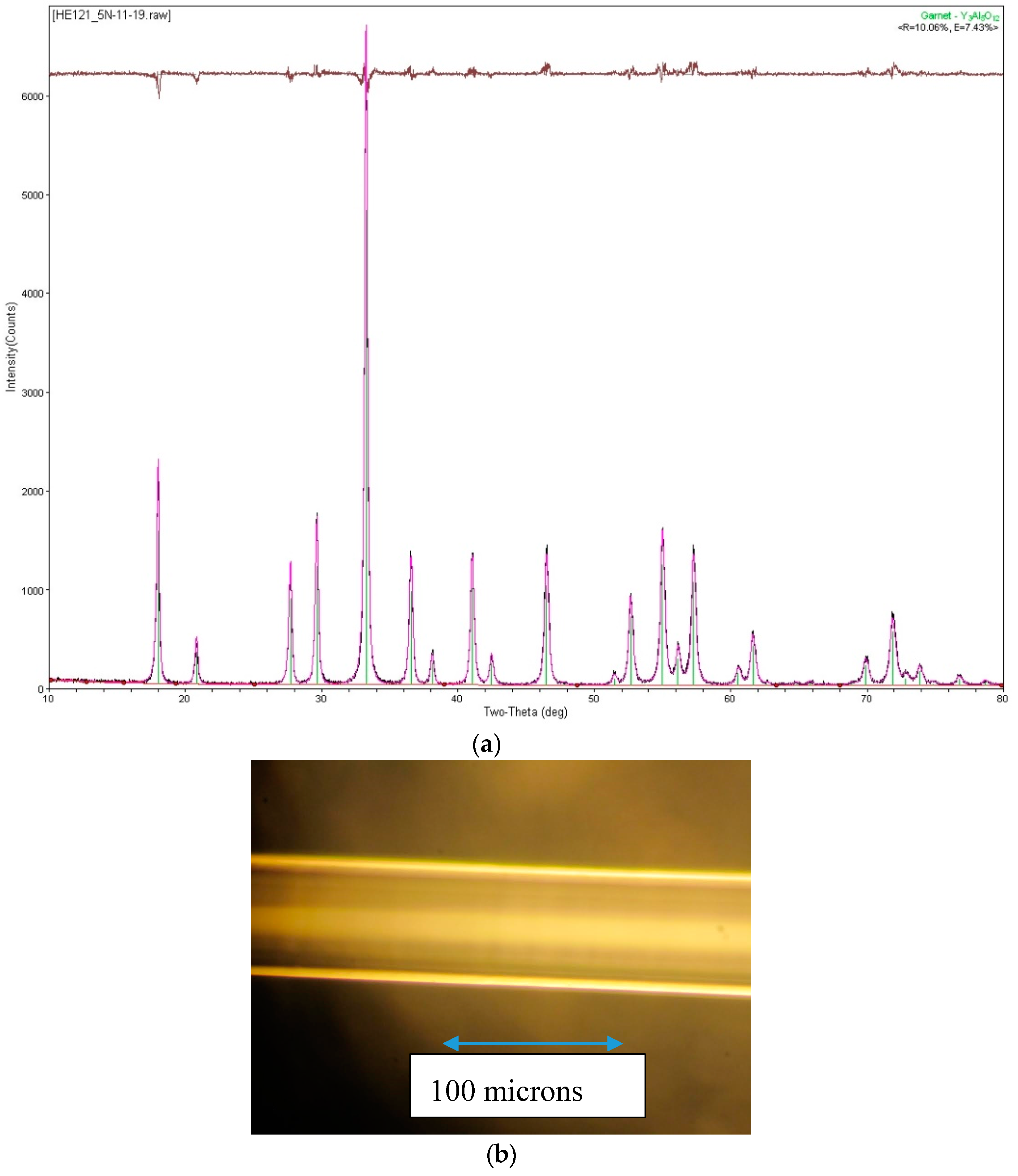
2O) as the Al source. X-ray diffraction studies confirmed that this novel procedure yielded single-phase cubic-face YAG (see
Figure 3a).
For such a characterization, the YAG prepared by sol-gel was allowed to gel fully. The powder was then placed in a crucible, crushed and heated at 500 °C (1 °C/min) for a dwell of 6 h to safely eliminate all citrates and nitrates. Finally, to produce crystalline YAG, the resulting powder was crushed in a mortar and pestle and reheated at 1000 °C (8 °C/min) for a dwell of 3 h. Before the XRD measurements were made, the previous powder was again lightly ground in a mortar and pestle and pressed into a bulk sample holder with a glass slide for analysis. Data was collected by a coupled Theta:2-Theta scan on a Rigaku Ultima-III diffractometer equipped with copper X-ray tube, para focusing optics, computer-controlled variable slits, and a diffracted beam monochromator.
To our knowledge, we are the first team to fabricate a transparent, crack-free YAG fiber cladding.
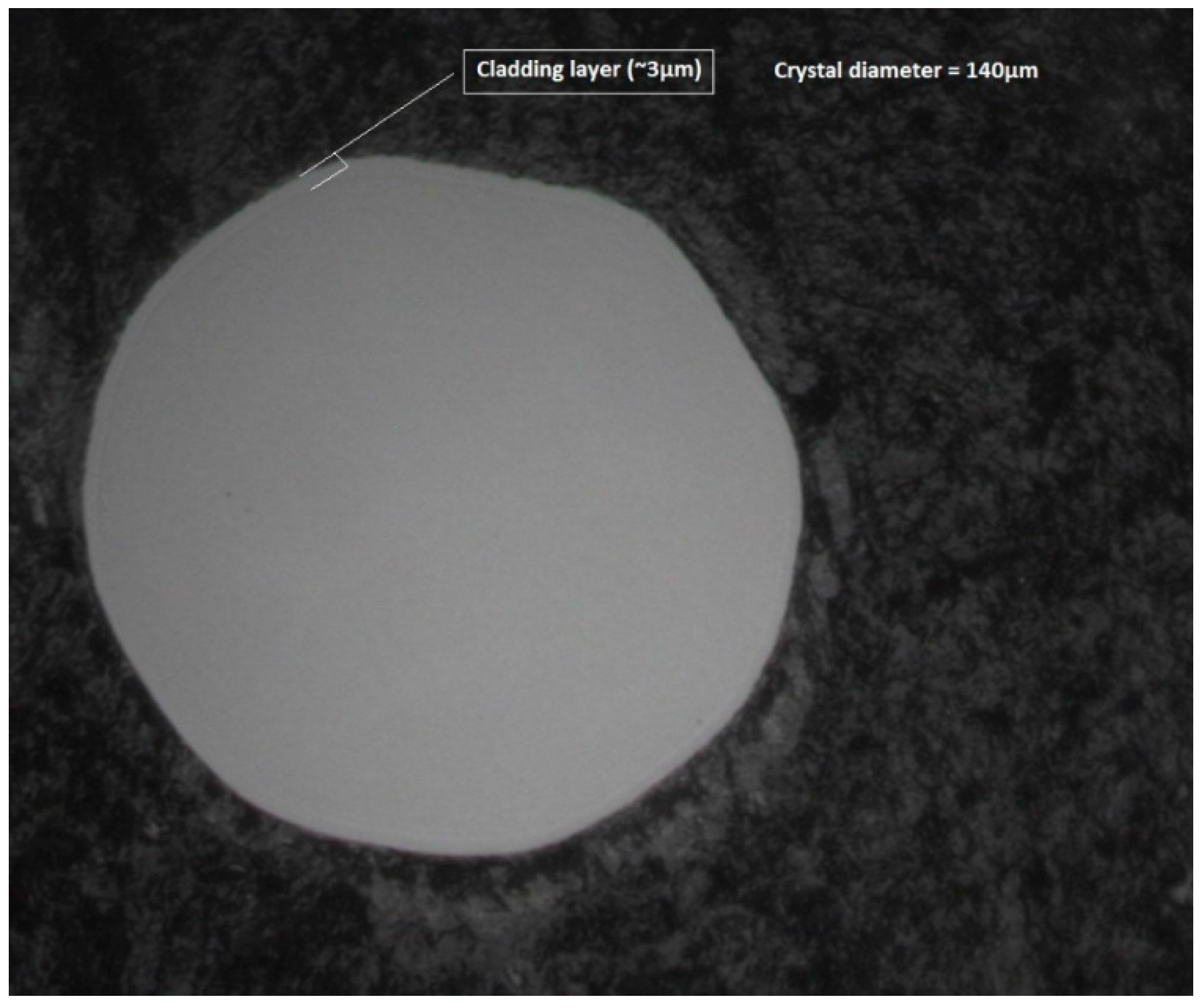
Figure 3b shows the fiber after a third coat, and
Figure 4 shows an undoped clad around a 140 µm core.
In order to tailor the NA of our fibers, we have invented and optimized the recipes for a variety of claddings with various indices of refraction. We can clad with pure or doped YAG, Al2O3, or silica.
Table 2 shows the scattering results. To gain maximum lasing efficiency, it is important to reduce scattering in single-crystals fibers to levels close to the ones of silica fibers (~10 dB/km). We have found throughout our experiments that the scattering loss can be reduced by annealing the fibers at 1100 °C for 12 h and/or by cladding them with pure YAG made by sol-gel. We have shown that we can grow the fiber by using our diameter control techniques and reach a scattering coefficient as low as 0.14 dB/m.
According to literature [
16], the YAG shows the absorption due to OH-related defects in both the starting source rod crystals and in the grown fiber. It is not known precisely why the losses in the visible wavelength decrease after the annealing process, but it is suspected that annealing in air might somehow help to decrease the oxygen-related impurities [
16]. As we can see, annealing in air and sol gel cladding, as well as using the diameter control techniques, have helped reduce the attenuation at 532 nm for the YAG fiber.
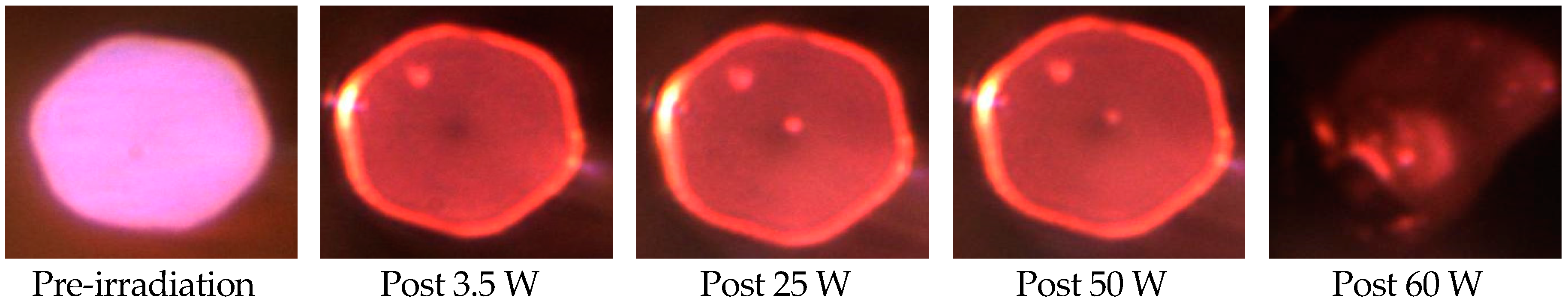
Damage threshold experiments (
Figure 5) at a wavelength of 1.07 microns in Continuous Wave (CW) regime revealed that our 100 micron diameter Nd:YAG fiber presents a damage threshold of 6 MW/cm
2. This is a very promising result, considering that the damage threshold for a bulk Nd:YAG crystal is around 1 MW/cm
2.
For Yb:YAG in pulsed regimes, we found out that at 6-ns pulses, the damage threshold for a 100 µm fiber was 80 J/cm2, and at 10-ps pulses, the damage threshold for an 80 µm fiber was 10.2 J/cm2.
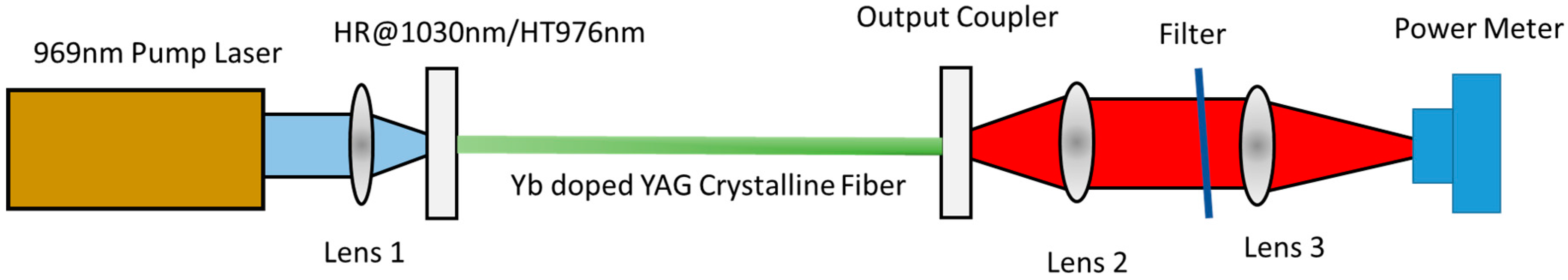
2.2. Laser Experiment
Experimental laser results were obtained with a diode-pumped, 100 µm diameter, 100 mm long, unclad Yb:YAG crystalline fiber, wherein both pump light and generated laser power are waveguided, as decribed in
Figure 6 [
17].
The core fiber was of excellent quality and we were able to obtain 54.1 W output power with 94.7 W of pump power. The slope efficiency was ~58.3% without AR coatings of the end faces. The high laser efficiency in waveguiding mode of the core indicates that the core quality is ready for further experiments with sol-gel cladding.
2.3. Amplifier Experiment
Small signal gain measurements were performed on an uncladded Yb:YAG rod, 500 µm in diameter and 30 mm long. For single-pass amplification, a single-pass linear gain of 7.4 was obtained for 29 nJ pulses of 5 ns duration at 1 MHz repetition rate; at this gain, no parasitic lasing was observed, indicating that 7.4 is not the limit. This may be due to a specific texture of an LHPG-crystals fiber surface as opposed to a mirror-like surface of the small diameter rods made by optical polishing or the micro-pulling-down technique. We also obtained a nearly diffraction limited amplified beam, and a polarization ratio exceeding 250:1 at all pump power levels. In addition, we observed no damage from multiple days of operation with 80 W of the pump power absorbed in a 3 cm long Ø0.5 mm crystal fiber.
These results allow us to expect the following in a Ø500 μm fiber: a very high damage threshold exceeding 30 J/cm2 for 6-ns pulses in combination with high small signal gain and high beam quality. We can obtain diffraction-limited output pulses with single-pulse energy of 19 mJ/pulse, which corresponds to peak power exceeding 3.2 MW/cm2. Moreover, 2 kW of the pump power absorbed within Ø500 μm, 3 cm long fiber bring the crystal only to 1/3 of its thermal fracture limit. If we assume 40% conversion efficiency, we can expect that a compact pulse amplifier with a kW output power can be built.
3. Discussion
The LHPG technique used for our work has proven very uniquely versatile and suited for high-power fiber lasers and amplifiers. The core-clad configuration of a classic glass fiber can be obtained via self-segregation at the center of the fiber for certain dopants such as Neodymium, or by post-growth processes such as sol-gel cladding. In this work, we have demonstrated the ability to grow single-crystal fibers over 900 mm long and 30 microns in diameter, with a variety of dopants. For Nd, the maximum doping level that could be attained was 4%, whereas 10% was reached for Yb, and 50% for Er. We established that Nd segregates and creates a natural core. For other dopants (Er, Yb, etc.) with a smaller ionic radius, no natural core occurred and a sol-gel process to clad the fibers with pure YAG was established and optimized. The best scattering results were obtained with cladded doped fibers grown with diameter control and annealed in air. Scattering as low as 0.044 dB/m was then obtained, proving that cladded fibers remain a low-loss medium. We have also demonstrated the great potential of the LHPG-manufactured crystal fibers, with their high gain, relatively simple and inexpensive manufacturing, simple amplifier geometry and excellent beam quality, thermal and mechanical properties and very high optical damage threshold.
These preliminary results are very promising and confirm the potential for single-crystal fibers to overcome the limitations (Stimulated Brillouin Scattering, etc.) of the glass fibers commonly used in fiber lasers, making them prime candidates for high-power compact fiber lasers and amplifiers. Although this article focuses on YAG fibers, our LHPG technology also allows the growth of materials for femtosecond lasers, such as Calcium Gadolinium Aluminum Oxide (CALGO), doped with Yb.
4. Materials and Methods
We prepared single-crystal doped YAG fibers from ceramic feeds. Once doped, YAG fibers were grown by the Laser Heated Pedestal Growth (LHPG) method, then annealed in a high-temperature oven. In an attempt to decrease scattering, some fibers were cladded with pure YAG and the scattering results before and after cladding were compared. We also analyzed the dopant distribution in the single-crystal Nd:YAG fiber.
4.1. Ceramic Feed Production
The initial crystal growth was carried out using a ceramic feed stock, the preparation of which is outlined as follows. Powders of 99.99% yttrium and aluminum oxide (American Elements, Los Angeles, CA, USA) were combined with various dopants (neodymium, erbium, or ytterbium) with concentrations between 1% atomic and 5% atomic and mixed in stoichiometric amount in a mixer mill (8000D SEPX sample prep) for 30 min. The resulting mixture was then cold-pressed into the form of a pellet, using seven tons of pressure in a one-inch die press. The pellet was sintered in air, inside a clean ceramic crucible, at 1200 °C for 24 h. After sintering, the pellet was diced into 0.9 × 0.9 mm diameter square feed rods, between 20–24 mm in length.
4.2. Crystal Fiber Growth
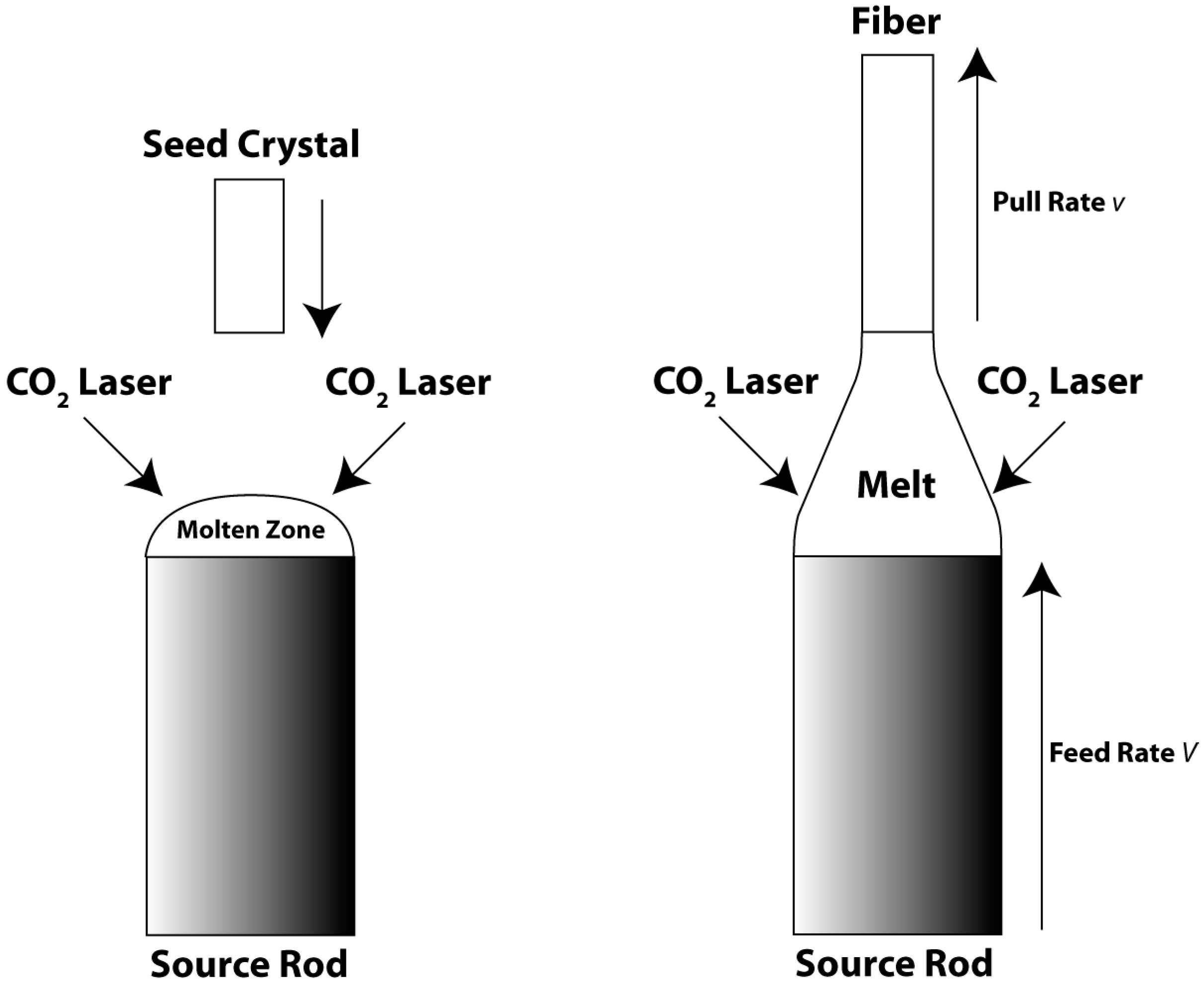
Single-crystal doped YAG fibers were grown by the Laser Heated Pedestal Growth (LHPG) method.
Figure 7 illustrates this method, which Haggerty invented in 1976 [
18].
A ceramic YAG feed rod with the desired dopant and dopant level is chosen and mounted in the LHPG growth machine. The tip of the feed rod is melted by a focused beam of infrared energy produced by a CO2 laser. A mechanical apparatus lowers a seed crystal with the desired orientation into this molten zone. Once the seed is wetted, it is pulled upwards, drawing the molten material up with it, forming the new crystal as it freezes. The melt is replenished by translation of the feed rod up into the melt as it is drawn out. The ratio between the seed pull rate, the initial diameter of the feed and the rate it is fed into the melt, determine the final diameter of the grown crystal. Typical reduction ratios are on the order of 2–3:1. The amount of power required to melt the initial ceramic feed rod is typically around 10–15 W in our system. Subsequent diameter reductions of the grown crystal require proportionally less power, with the final reduction requiring less than one watt of power. The rate at which the crystal is grown is typically 1–2 mm/min for the growth of 500–1000 µm diameter crystals. The final fiber, 30–120 µm in diameter, is grown at 3–5 mm/min. Typical fibers are grown from 10–90 cm in length in this way. The crystal fibers become more flexible as their diameter is reduced, with fibers of ~100 µm in diameter having a bend radius of ~1 cm, and thinner fibers having correspondingly tighter bending radii.
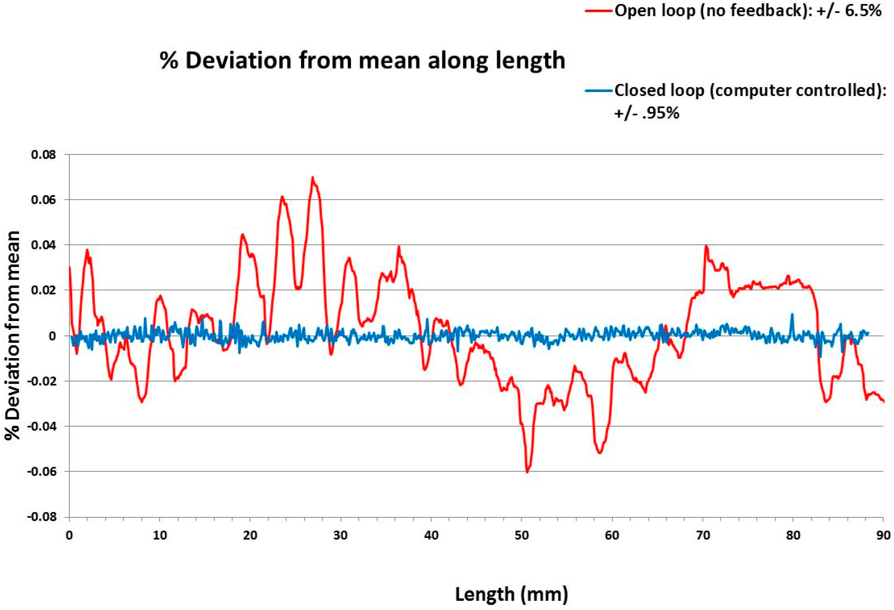
In an attempt to control the uniformity of the crystal fiber diameter, a computer-controlled feedback system was implemented. The system focuses a red laser beam onto the growing fiber and produces a series of interference fringes. These fringes are imaged onto a Charge Couple Device (CCD) line camera and interpreted by a software program that displays the calculated fiber diameter. In open-loop growth, or without any computer feedback control, the diameter of the fiber will fluctuate with any change in the diameter of the feed or change in laser power. The software attempts to correct for this by allowing computer control over the feed motor speed, influencing the volume of the melt and, ultimately, the diameter of the grown fiber. The level of computer control in the closed-loop setting is adjusted by modifying its gain settings.
Figure 8 indicates that the feedback system reduces the maximum diameter fluctuations from 7% to less than 1%.
4.3. Annealing and Polishing of Crystal Fiber
Post growth, the approximately 4-inch long fibers were annealed in a high-temperature oven in air. In order to maintain a clean annealing environment, the fibers were placed inside a covered alumina dish, wide enough in diameter to be at least 3–4 times the bending radius of the fiber. The oven was ramped up at a rate of 5 °C/min to a temperature of 1000 °C, held at this temperature for 12 h, and then allowed to cool down until the fibers reached room temperature.
Following the annealing, the tip of each fiber was placed inside a close-fitting glass capillary tube and held in place by a low melting adhesive (Crystal Bond). An ULTRAPOL End and Edge polisher was used with a series of aluminum oxide polishing pads of decreasing grit size in order to produce a laser grade polish on the fiber end faces.
4.4. Sol-Gel Cladding
An Example: YAG Cladding
To decrease the amount of bulk scattering, sol-gel YAG fiber clad materials were explored. The material was prepared using sol-gel mechanisms that required very low reacting temperatures (under 100 °C). Yttrium aluminum garnet (YAG) was made via the hydrolysis and condensation reaction of yttrium oxide (Y2O3) and aluminum nitrate Al(NO3)3. A modification of common sol-gel synthesis procedure was used to prepare YAG. The reaction was carried out in acidic media to prevent flocculation and with the use of citric acid, a pacifier. Aluminum nitrate monohydrate (>98%), yttrium oxide (99.99%), 1.0 M acetic acid and citric acid monohydrate (98%) were all purchased from the Aldrich Chemical Company. Yttria was firstly dissolved in 0.2 M acetic acid by stirring at 60 °C for 2–3 h while covered. The aluminum precursor was then added along with citric acid and the mixture was stirred at 80 °C.
After approximately two hours, the increase in viscosity was evident. However, the solution was not allowed to reach gelation in order to produce thin coatings that were crack-free. To minimize defects, the substrates were cleaned thoroughly by soaking in acetone and then in water in an ultrasonic bath for several minutes.
The YAG substrate was dip-coated in the sol at 1–10 cm/min and allowed to dry very slowly in air for 24 h. Once dry, the sample was heated for a dwell time of three hours at 500 °C. To produce thicker coatings, the coating and drying process was repeated until the desired size was achieved.
4.5. Dip Coating
The YAG fiber was dip-coated in the sol at 1–10 cm/min and allowed to dry very slowly in air for 24 h.
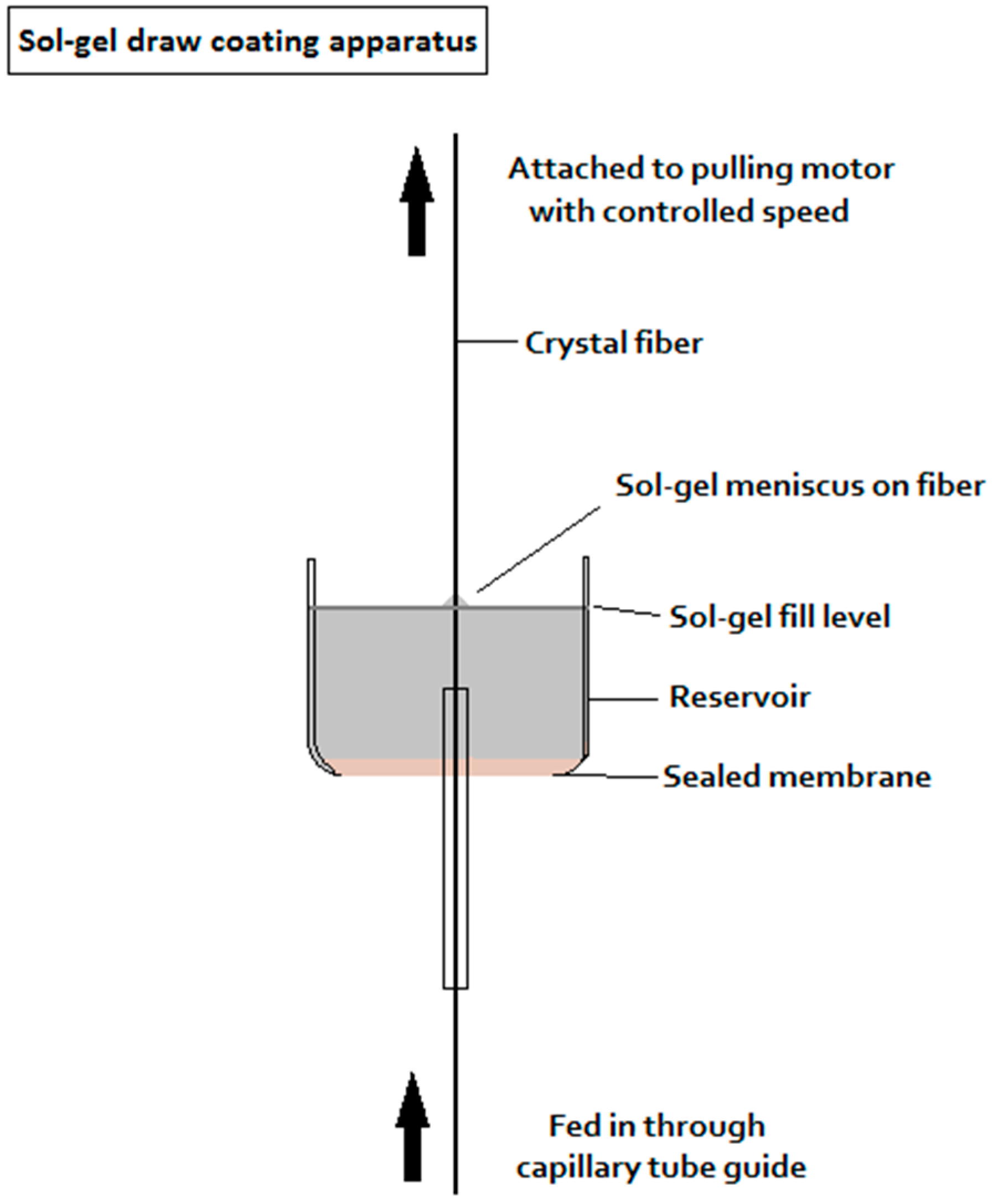
To coat a fiber thinner than 140 µm, our patent-pending draw coating technology is used. A reservoir such as the one depicted in
Figure 9 is used. The fiber is inserted inside a capillary tube on the lower side of the container. Once the fiber is visible in the top end of the capillary tube, a very narrow and short piece of tape may be used to make sure the fiber does not fall through until it is secured. Next, a string with a small amount of Crystal Bond is brought very close to the top face of the crystal. The string is then aligned carefully with the fiber and approximately 1 mm past the end of the fiber. The Crystal Bond at the end of the string may then be gently heated with a torch until it is soft and the string and the crystal are brought together. After the crystal bond is allowed to cool, the reservoir may be filled with the YAG sol-gel. The YAG gel is then coated on crystal by pulling up the string at a controlled rate driven by a motor. For YAG, this draw rate may be anywhere from 18 mm/min to 41 mm/min, depending on the viscosity of the gel. The film is then allowed to dry very slowly for approximately 23–26 h. When drying in air, humid conditions must be avoided. Once dry to the touch, the sample is heated to 500 °C for three hours at a ramp rate of 1 °C/min.
Once dry, the sample was heated for a dwell time of three hours at 500 °C. Cladding of thickness <3 microns is typically obtained with that process. To produce thicker coatings, the coating and drying process was repeated until the desired size was achieved.
Scattering Measurement
Bulk scattering losses inside the Yb:YAG fibers were measured by using an integrating sphere. The major components of the scattering setup are: a two-inch diameter integrating sphere (Lab sphere 4P-GPs-020-sL, Spectralon); a chopper that decreases the noise during measurement at low scattering levels; and, a lock-in amplifier (SR810 DSP). A 532 nm (5 mWatt) diode laser beam is sent through the optical chopper, which also sends a reference signal to the lock-in amplifier. A small fraction of the beam is sent to a laser beam monitor detector. The beam must be focused into the sample crystal. The laser beam can pass through the crystal and the portion of the beam that is scattered by the crystal is captured and reflected by the integrating sphere and is detected by the semiconductor detector (Silicon PIN detector, Laser Components, Bedford, NH, USA). The output from the detector is then sent to the lock-in amplifier.
The measurement technique involves placing a four-inch long fiber within the integrating sphere and focusing the laser radiation in and through the sample. If both end faces of the sample are not allowed to reflect light directly into the integrating sphere, only light scattered within the sample bulk is measured by the detector. Blocking the exit port and measuring the detector's signal gives a relative measurement of the total power into the sample. Comparison of the signal obtained with the sample inside and outside of the sphere gives an absolute determination of the optical scattering losses. Chopping the laser beam allows phase-sensitive detection, enhancing the signal-to-noise ratio at low scattering levels.
4.6. Energy-Dispersive X-Ray Spectroscopy (EDS)
An EDS machine from BALAZS NanoAnalysis was used for the elemental analysis of the polished end faces of Nd:YAG crystal (diameter of 500 μm, length of 8 mm). Electron beam excitation is used in a scanning electron microscope (SEM). X-ray beam excitation is used in X-ray fluorescence (XRF) spectrometers. A detector (Si(Li) detector cooled with liquid nitrogen to cryogenic temperatures) was used to convert X-ray energy into voltage signals; this information is sent to a pulse processor, which measures the signals and passes them onto an analyzer for data display and analysis.
4.7. Damage Threshold Measurements
Spica Technology measured the damage threshold of a 100 micron diameter Nd:YAG and Yb:YAG single-crystal fibers that we fabricated. For the Nd:YAG fiber, they focused a CW laser at 1 micron into the fiber and increased power incrementally until they observed either a change in transmission or physical damage. For the Yb:YAG fibers, they measured the damage thresholds using 6-ns pulses and 10-ps pulses.


