1. Introduction
Bandgaps in periodic structures have been studied intensively due to their use for filtering and shielding of waves and vibrations [
1,
2,
3]. The existence of bandgaps for electromagnetic waves (photonic bandgaps) [
4,
5,
6], for elastic waves (phononic bandgaps) [
7,
8,
9] and for acoustic waves [
10], has been demonstrated in numerous theoretical and experimental works. More recently, the possibility for obtaining coupled photonic/phononic bandgaps has been demonstrated [
11,
12]; the co-existence of these bandgaps is sometimes referred to as phoxonic bandgaps [
13].
Bandgaps in coupled elastic-acoustic (or acoustic-mechanical) structures have received much less attention. One of the few studies in this area [
14] deals with bandgaps in periodic plates and cylindrical shells with heavy fluid loading. Specifically, the field of combined acoustic-mechanical bandgaps for thin-walled periodic structures that vibrate in air is unexplored. For micro-mechanical components and devices with a large internal acoustic pressure, such as, e.g., cellular phones, hearing aids or pressure transducers, the consideration of fully-coupled acoustic-mechanical vibrations and wave propagation is essential for an accurate prediction of the dynamic behavior, and the coupling phenomena are often responsible for acoustic-mechanical feedback problems and resulting high vibration levels. In order to investigate the possibility for using bandgap structures to alleviate vibration problems in such devices, a fundamental study of the bandgap properties must be performed, including the full coupling of the acoustic pressure and mechanical vibrations.
Bandgaps in periodic bi-material (and planar) plates have been studied by different research groups [
15,
16], and guidelines of how to create gaps for bending waves have been provided. Due to the relatively low wave speed of bending waves in thin plates, it is possible to create gaps in the audible frequency range with a structural periodicity in the order of centimeters. Furthermore, the bending waves couple directly to the acoustic pressure field (unlike in-plane waves), which make periodic plate structures interesting for applications in micro-mechanical devices. However, to the authors’ knowledge, the effect of the coupling between the plate vibrations and the surrounding acoustic medium with respect to bandgap properties has not been studied previously.
In this paper, we illustrate the importance of including the acoustic-mechanical interaction by computing the dispersion relation (wave propagation characteristics) for a periodic planar plate-structure with and without a surrounding acoustic medium and by calculating the corresponding vibrational response of a finite structure (
Section 2 and
Section 3). Then, in
Section 4, we conduct a more fundamental study where we investigate the possibility for creating coupled acoustic-mechanical bandgaps in a one-dimensional corrugated plate structure. In
Section 5, we discuss the results and present an outlook for future work.
2. Bandgaps in Planar and Periodic Bi-Material Plates with Acoustic Loading
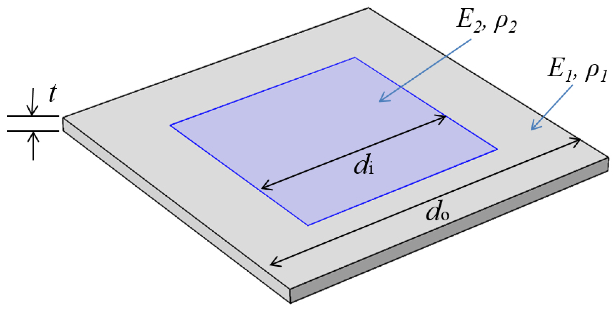
First, we analyze the wave propagation characteristics in a periodic and planar plate structure and specifically investigate the influence of the acoustic coupling. A chosen repetitive unit of the periodic plate, the unit cell, is shown in
Figure 1. We consider a square cell with side-length of
m and a thickness of
mm. The base (or matrix) material is light and soft with a mass density of
kg/m
, a Young’s modulus of
MPa and a Poisson’s ratio of
. The periodicity is created by a square inclusion placed centrally in the unit cell. The heavier and stiffer inclusion has a side-length of
m, a mass density of
, a Young’s modulus of
GPa and a Poisson’s ratio of
.
A standard way of characterizing the wave propagation in a periodic material is to compute the dispersion relation and present it in a band diagram. We will not go into detail here with the basic modeling details (but we will to some extent return to this issue when dealing with the corrugated plate in
Section 4). Numerous books and papers may be consulted for computational details, e.g., [
1]. We have here performed the computations using a finite element implementation in Comsol using shell elements for the plate structure and using a standard linear elastic material model. Additionally, we have added the option of including an acoustic layer on top of the plate structure bounded by a sound hard wall boundary at the top. A standard linear model for the acoustic medium is used, and the coupling between the two domains is performed directly in the Comsol implementation.
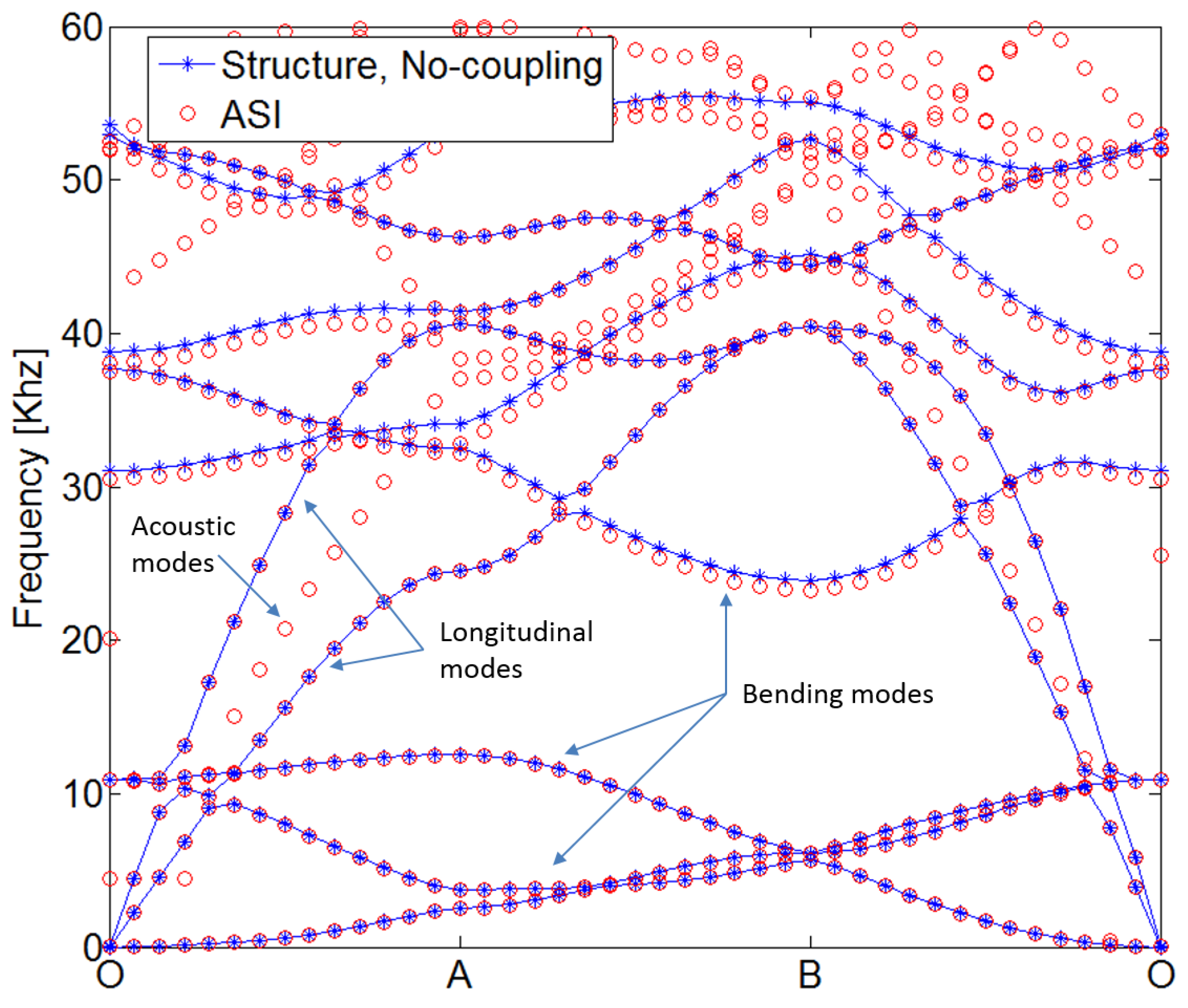
In
Figure 2, the resulting band diagram is shown both in the case of the pure plate structure, and with a
mm-thick acoustic layer added on top of the unit cell. The band diagram illustrates the computed propagation modes with the propagation frequency along the vertical axis and the reduced wavevector along the horizontal axis. The band diagram provides a complete picture of the possible modes propagating in the periodic medium.
In
Figure 2, we notice a wide bandgap for flexural waves in the plate, between approximately 12 and 24 kHz. This gap is seen to exist both for the pure plate model, but also with acoustic coupling included. It is noted that the presence of the acoustic layer does not significantly affect the bending wave modes, even though the plate is made from a very light and flexible material. This is a natural consequence of air coupling, which usually results in a weak coupling scenario. In addition to bending modes, we notice the presence of the two longitudinal modes in the plate. These modes cross the flexural bandgap frequency range and are, due to their in-plane nature, not affected by the acoustic medium. Finally, we can notice the pure acoustic modes that are seen to exist in the entire frequency range and, thus, also in the frequency range corresponding to the flexural wave bandgap.
3. Finite Coupled Systems
The footprint of a bandgap on the vibrational response of a finite structure created from the periodic material is usually clear and unambiguous. If a sufficient number of repetitive units are used, a large reduction in the vibrational response is noted within the bandgap frequency range. A possible exception exists in the form of isolated modes appearing due to edge or boundary effects [
17].
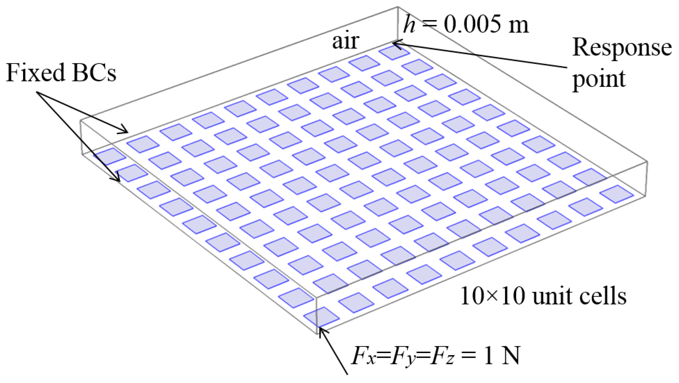
Figure 3 shows such a finite structure assembled from
plate unit cells with an acoustic medium on top. The plate is excited by a time-harmonic force
acting at one corner of the structure, and the response is measured as the vertical vibration amplitude in a position close to the opposite corner.
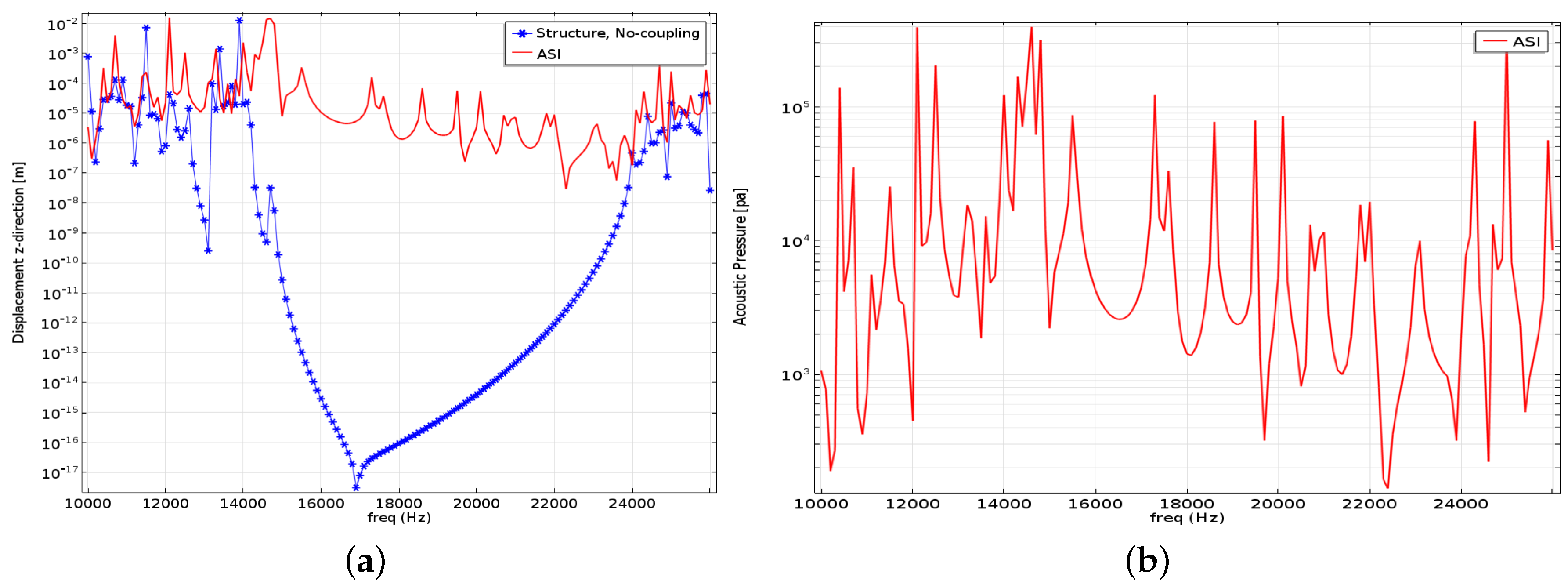
In
Figure 4a, we show the structural response with and without the coupling to the acoustic medium. Without coupling, we see a significant drop in the response in a frequency range that corresponds to the flexural bandgap frequency range, however, with some modes appearing in the lower range due to boundary effects. When we include the acoustic coupling, the effect of the acoustic modes noticed in
Figure 2 is clearly seen in the vibrational response. In this case, the bandgap footprint on the response practically disappears, and this occurs even though the coupling is weak. The effect is also clearly seen in the acoustic response at the opposite corner (shown in
Figure 4b), which does not reveal the presence of a bandgap.
It should be emphasized that also longitudinal waves may propagate through the plate. However, these do not couple to the vertical response in the planar plate. However, if the plate is connected to other plates in an out-of-plane assembly, the longitudinal waves may excite flexural waves in neighboring plates, and considering longitudinal waves also would be essential.
Hence, we can conclude that with a planar periodic plate structure, we may quite easily create bandgaps for flexural waves, although this normally requires a rather large contrast between the material properties of the matrix and inclusion material. However, due to the existence of acoustic modes and the coupling between the acoustic pressure and the structural vibrations (although weak), we cannot directly use this to control the vibrational properties of the corresponding plate structures.
4. Bandgaps in Corrugated Channels and Beam Structures
Motivated by the investigation conducted in the previous sections, we will now examine the possibility for combining a structural bandgap and a bandgap in the acoustic domain. For this purpose, we propose to use a corrugated plate so that we introduce a geometrical periodicity both in the structural and in the acoustical domain and, therefore, potentially bandgaps in both domains. However, it needs to be investigated if this periodicity is able to introduce significant and overlapping bandgaps in the two domains and also to what extent the physical coupling between the mechanical and acoustic domains will affect such coupled bandgaps.
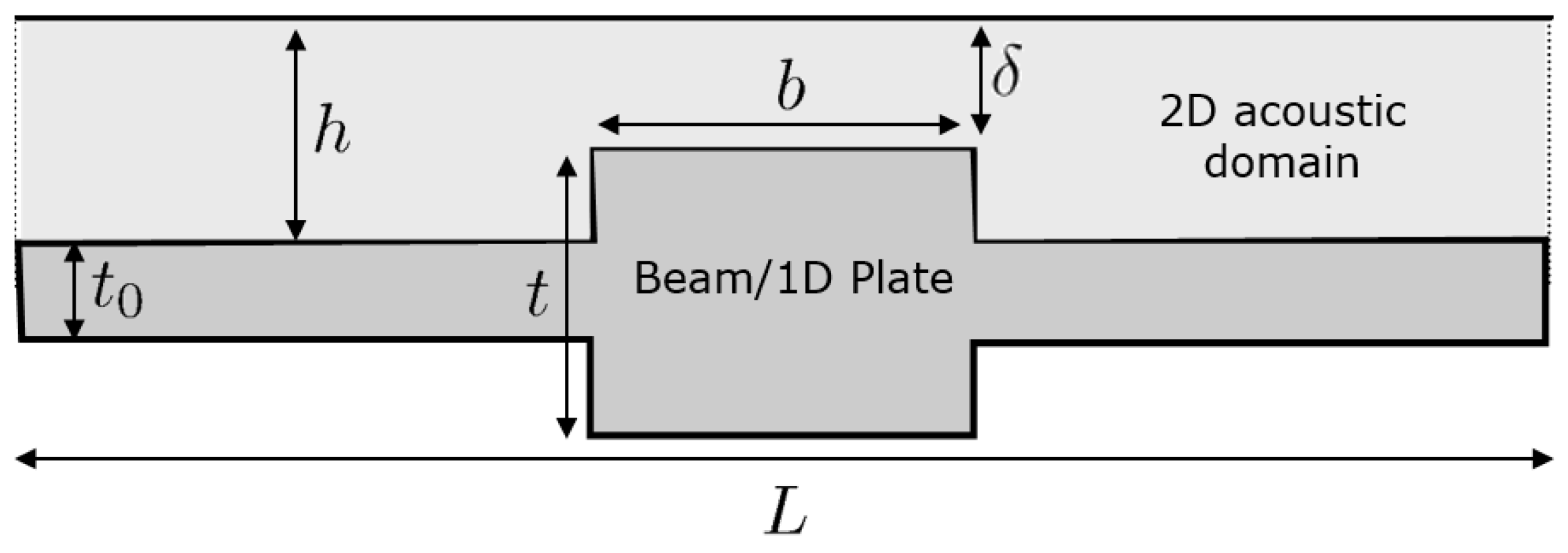
The basic setup is illustrated in
Figure 5, where we for simplicity examine a system with 1D periodicity represented by a unit cell of length
L.
4.1. Acoustic Wave Propagation in Periodic Channels
As the first step in the analysis, we investigate the propagation characteristics of acoustic waves in the one-sided periodic channel using a simple finite element model.
In the following, we will assume that the depth of the channel is sufficiently shallow so that in the frequency range of consideration, we will be below the cut-on frequency of higher-order out-of-plane modes and, hence, do not have any pressure variation in the channel perpendicular to the plane. Thus, we can reduce the equation for the time-harmonic pressure distribution to the following 2D equation:
where
is the unknown pressure variation,
is the wave speed and
ω the wave frequency.
We now introduce the Bloch wave condition for propagating waves in a periodic medium [
1,
18]:
where
is now
L-periodic and
k is the wavenumber. Inserting Equation (
2) into (
1) yields:
We can easily rearrange this equation into:
and then cancel the common exponential term, so that we obtain:
which is now directly amenable to a finite element procedure. The corresponding boundary conditions take the form of sound hard wall conditions both at the upper wall and the lower interface (in the case of a non-vibrating plate), specified as
.
Employing a standard finite element procedure results in the following eigenvalue problem for the acoustic medium:
in which
is a wavenumber-dependent and complex matrix given as:
and the corresponding element matrices are given as:
in which
is the acoustic shape function vector for the chosen rectangular four-node bilinear element.
Figure 6a shows the dispersion relation computed for the homogeneous channel based on a chosen length of the unit cell
cm (which is, of course, arbitrary in the case of a homogeneous channel). Gaps in the band structure where the band is artificially folded (at
) can be introduced by creating an inhomogeneity. For the homogenous channel, we have an analytical solution for the folding point:
m/s
kHz for
cm.
Figure 6b shows that by introducing an inhomogeneity in the form of a stub (the corrugated plate) of a relative length of
of the unit cell length and a relative height of
, a gap is opened symmetrically around the folding point. It can be shown that any inhomogeneity will open up the gap, and the wider and higher the stub (plate corrugation), the broader the gap. In order to validate the numerical model for the inhomogeneous acoustic channel, we have conducted a similar calculation for the first band using Comsol. The compute values shown as discrete markers in
Figure 6b show a good agreement.
4.2. Wave Propagation in the Corrugated Plate
Now, we will compute the corresponding dispersion relations for the periodic plate. For simplicity, we will base the derivation on Kirchhoff plate theory and search for geometrical parameters and frequency ranges where we can expect to have overlapping gaps in the frequency response for both the acoustic and the bending waves.
The one-dimensional plate equation is given as:
where
is the transverse displacement and
D is the plate bending rigidity.
In a similar way as for the acoustic equation, we introduce the solution form using the Bloch wave condition:
and insert this into Equation (
12):
and can then write the governing equation as:
after canceling out the common exponential term.
Furthermore, here, we employ a finite element discretization of the one-dimensional plate using simple two-node elements and derive the final finite element formulation as:
in which
is a wavenumber-dependent and complex stiffness matrix given as:
and the corresponding element matrices are given as:
where
is the plate shape function vector for the two-node element.
Again, we use the fundamental relations for a homogenous plate to tune the geometry to open a gap in the desired frequency range.
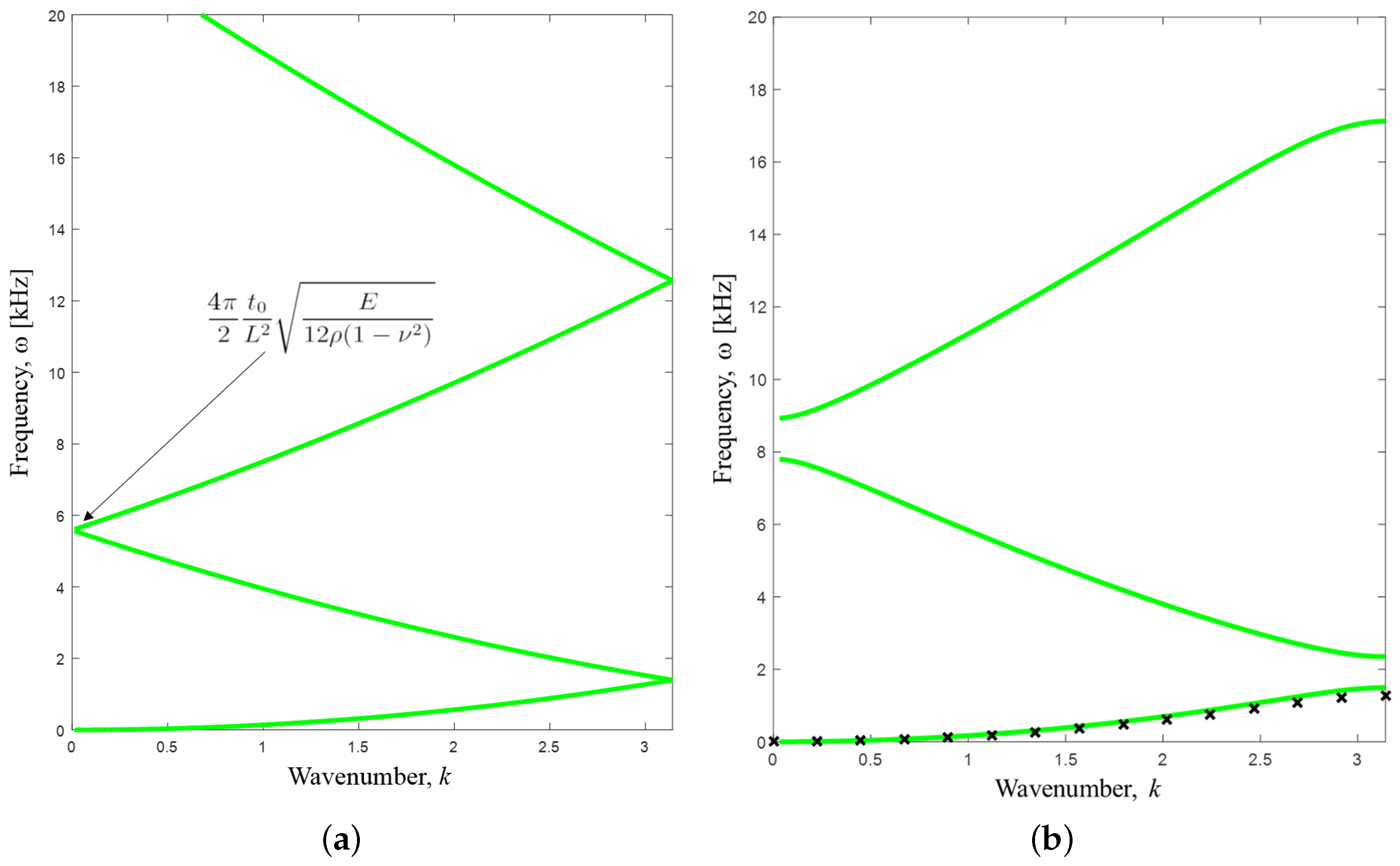
Figure 7a shows the dispersion relation for the homogeneous plate with the same length of the unit cell as for the acoustic channel (
cm). The folding point frequency between the second and the third band is given as
, which for the chosen parameters for
E,
ρ and
(see
Table 1) is slightly below
kHz. Thus, we can expect that by introducing an inhomogeneity, we can open a gap somewhat below the frequency range of the acoustic gap in
Figure 6b. As we see in
Figure 7b, a gap is opened, however, at a slightly higher frequency due to the increased stiffness of the corrugated plate. Again, we have performed supplementary calculations using Comsol for the inhomogeneous plate in order to validate the numerical procedure. The first band for bending waves is here obtained using a 2D solid model with a plane strain assumption. The small discrepancies highlight the limitations of the plate model, but qualitatively, the results match well.
4.3. Coupled Analysis
The two previous sections provide simple results based on uncoupled FE eigenvalue problems. Based on these results, we can further tune the geometrical parameters in order to create overlapping gaps in the two band diagrams. However, clearly, this will only provide a first indication of possible coupled bandgaps. In order to capture the full behavior, we will need to solve the fully-coupled problem in which the acoustic pressure acts as a load on the plate and the plate vibrations in turn influence the boundary condition for the acoustic medium at the interface to the plate.
Introducing this coupling into the previously presented notation yields the full eigenvalue problem:
where
is the density of the acoustic medium and
is a coupling matrix defined by:
where the acoustic shape function vector is evaluated at the interface (intf) to the plate element.
4.4. Results
Based on the above considerations, we now choose a final set of geometrical parameters that define the periodic channel and plate (
Table 1).
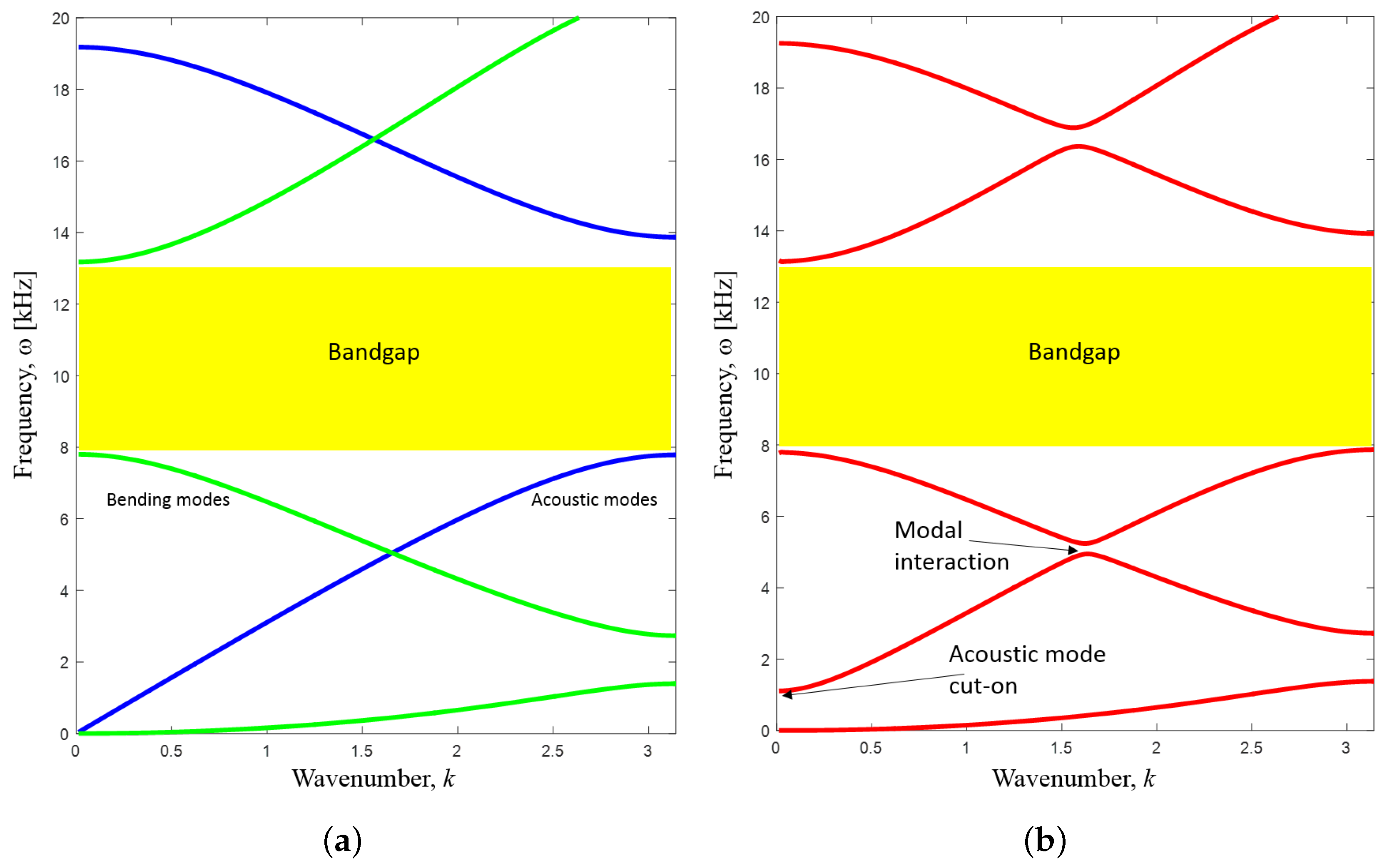
Figure 8a shows the dispersion relations for the uncoupled acoustic and plate problems. The plate bending modes are shown in green, and the acoustic modes are shown in blue. It is seen that an overlapping gap is opened between the second and third bending modes and between the first and second acoustic modes. This corresponds to a common bandgap in the range from approximately 8–13 kHz.
Figure 8b shows the corresponding results when solving the full coupled eigenvalue problem. It is clear that in general, the effect of the coupling is rather small, as was also seen for the two-dimensional plate problem in
Figure 2. The location of the bands is only marginally changed, and thus, the bandgap from 8–13 kHz prevails. However, other important effects are noted. Firstly, due to the interaction between the modes, the acoustic and structural bands no longer cross. This phenomenon of modal or eigenvalue interaction is well known [
19]. Furthermore, we also note the well-defined cut-on frequency for the fundamental acoustic mode close to
kHz.
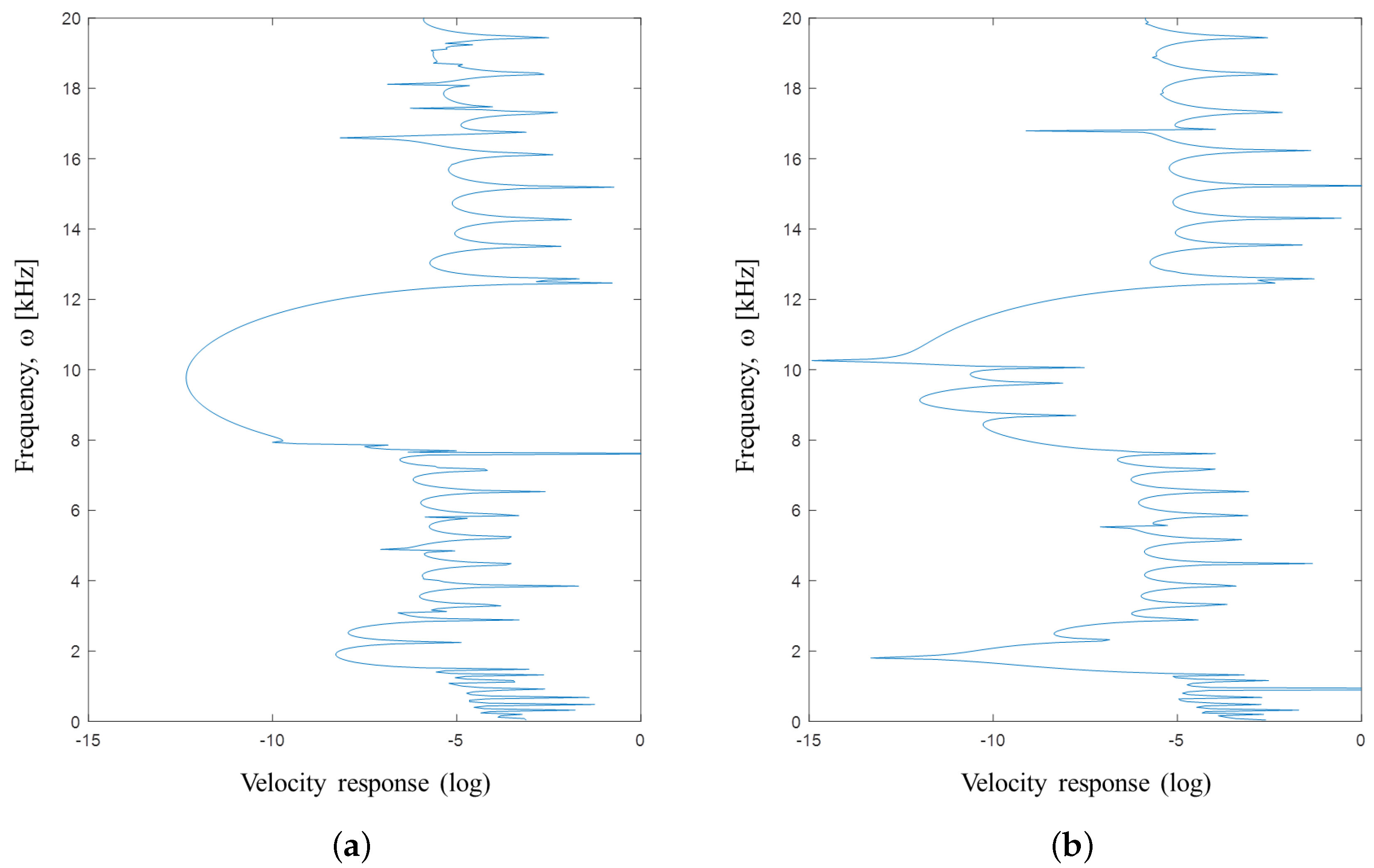
To highlight the importance of the overlapping bandgaps, we have additionally computed the frequency (velocity) response for a finite structure consisting of 10 repeated unit cells. We have applied a periodic vertical excitation in one end and compute the corresponding velocity amplitude in the opposite end.
Figure 9a shows the response for the structure corresponding to
Figure 8b. Here, the full bandgap from 8–13 kHz is clearly reflected in the response (with some isolated modes appearing close to the upper limit of the range).
Figure 9b shows the response for the same plate, but with the distance to the upper boundary increased (parameter
h in
Figure 5) so that the acoustic band structure corresponds to the results in
Figure 6b. In this case, the overlapping bandgap frequency range is reduced to 10–13 kHz with distinct response peaks appearing in the range from 8–10 kHz due to the presence of acoustic resonances in the cavity. The effect is noted to be less pronounced than for the corresponding 2D case, since the modal density is lower, but if more unit cells are included in the finite structure, then the number of acoustic modes will increase correspondingly.
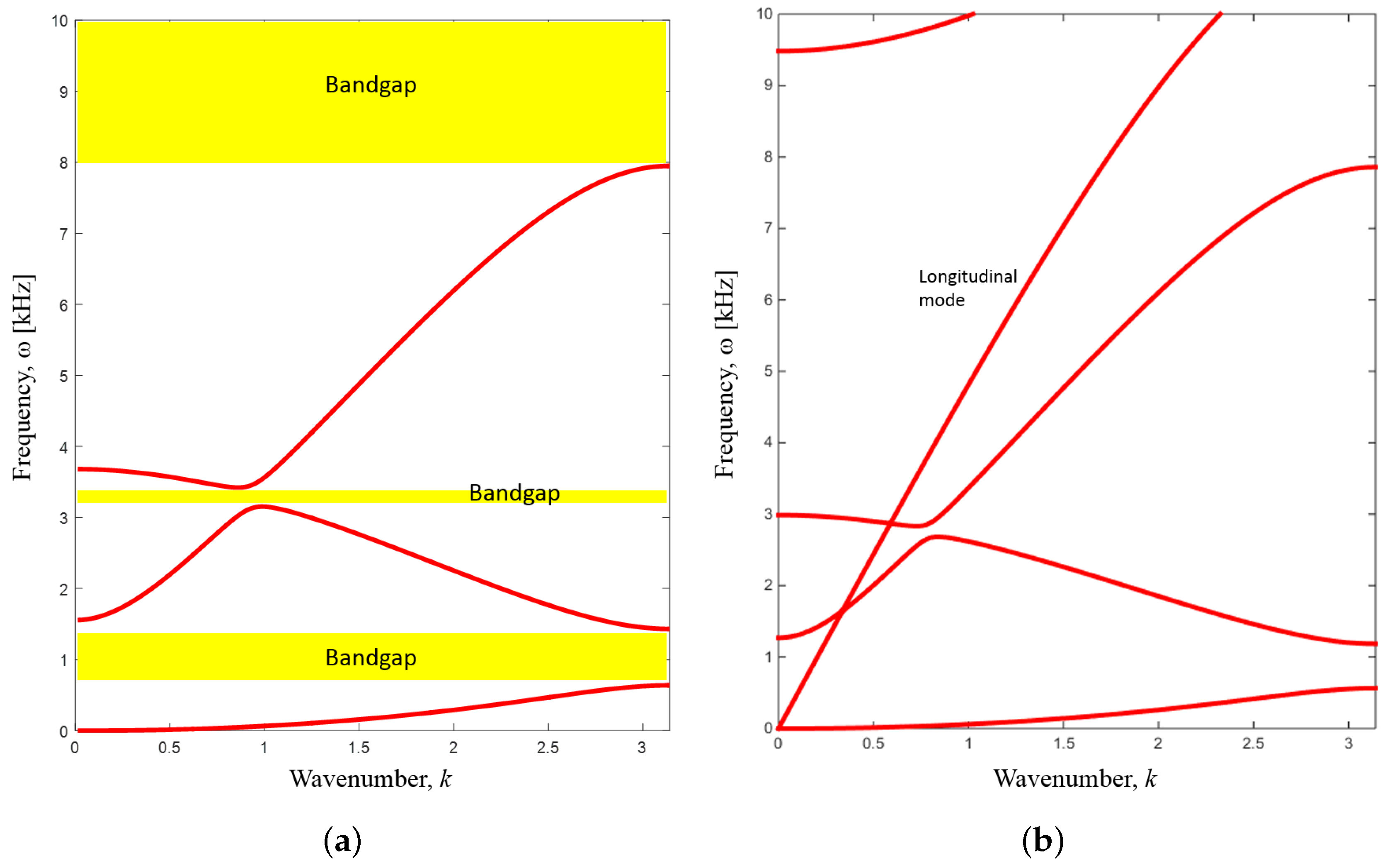
In order to exploit the effect of the cut-on frequency, we may now adjust the parameters of the system by making the plate both thinner and lighter. The results are shown in
Figure 10a. We experience a bigger difference between the result for the fully-coupled and uncoupled analysis due to the stronger coupling (not shown), but we also now see that a clear gap opens up in the low frequency range between the first bending mode and the cut-on frequency for the fundamental acoustic mode. Additionally, the modal interaction between bands also introduces an additional (narrow) bandgap. It should be emphasized, though, that the existence of the cut-on frequency for the fundamental acoustic mode is not linked to the periodicity of the acoustic channel, but is also found for a straight channel configuration, e.g., as was noted in the analysis of bandgaps in periodic (an planar) plates for heavy fluid loading [
14].
In order to validate the results for the coupled analysis, we have performed a Comsol computation for the coupled system based on a 2D solid model (plane strain). The results are shown in
Figure 10b. Discrepancies are noted especially for the higher order bending modes, which is to be expected due to the limitations of the plate model. However, the results match qualitatively, and the existence of the cut-on frequency (although shifted downwards) and the corresponding lower frequency bandgap is validated.
5. Discussion
We have demonstrated the possibility to create bandgaps for a simple coupled acoustic-mechanical system. The periodicity was created by considering a plate with a one-dimensional corrugation leading to a geometrical periodicity both in the plate and in the acoustic channel. By using simple design criteria based on analytical predictions, it was shown to be possible to create overlapping bandgaps in the two domains. In the example, the gap appeared between the second and third band for the bending waves in the plate and between the first and second band in the acoustic domain. The gap was between 8 and 13 kHz, thus in the attractive audible frequency range. Furthermore, we saw that the existence of gaps prevailed also when considering the fully-coupled acoustic-mechanical model and also when the simple plate model was replaced by a more realistic solid model using a Comsol model. Additionally, the fully-coupled models also showed the emergence of new gaps in the frequency spectrum due to modal interaction and due to a cut-on frequency for the fundamental acoustic mode.
The results are a first step towards designing coupled acoustic-mechanical system that may exploit the bandgap phenomenon to mitigate the propagation of waves and disturbances. Further studies should address the case of the two-dimensional periodicity of the corrugation, which undoubtedly makes the creation of coupled gaps more challenging. Naturally, the periodicity in the acoustic channel can also be enforced by other means, such as a corrugation of the top wall. This will allow for the use of a planar plate, such as shown in
Section 1 of the present paper, and also allows for introducing different periodicities in the acoustic and plate domains.
Importantly, the complication of the presence of longitudinal waves in the plate structures should be addressed since these are known to strongly affect the vibrational properties of assembled plate structures. Previous studies have shown the possibility of combining bandgaps for bending and longitudinal waves [
20], and combining this with the acoustical bandgap, in order to achieve truly full bandgaps, is a natural next step.
Acknowledgments
The work of Junghwan Kook was funded by the Danish Council for Independent Research—Individual postdoctoral grants.
Author Contributions
Junghwan Kook performed the analysis with the Comsol model in
Section 2 and
Section 4. Jakob S. Jensen performed the MATLAB analysis in
Section 3 and
Section 4. Jakob S. Jensen wrote the draft of the paper.
Conflicts of Interest
The authors declare no conflict of interest.
References
- Brillouin, L. Wave Propagation in Periodic Structures, 2nd ed.; Dover Publications: New York, NY, USA, 1953. [Google Scholar]
- Mead, D.J. Wave propagation in continuous periodic structures: Research contributions from Southampton, 1964–1995. J. Sound Vib. 1996, 190, 495–524. [Google Scholar] [CrossRef]
- Hussein, M.I.; Leamy, M.J.; Ruzzene, M. Dynamics of Phononic Materials and Structures: Historical Origins, Recent Progress, and Future Outlook. Appl. Mech. Rev. 2014, 66, 040802. [Google Scholar] [CrossRef]
- Yablonovitch, E. Inhibited spontaneous emission in solid-state physics and electronics. Phys. Rev. Lett. 1987, 58, 2059–2062. [Google Scholar] [CrossRef] [PubMed]
- John, S. Strong localization of photons in certain disordered dielectric superlattices. Phys. Rev. Lett. 1987, 58, 2486–2489. [Google Scholar] [CrossRef] [PubMed]
- Joannopoulos, J.D.; Meade, R.D.; Winn, J.N. Photonic Crystals; Princeton University Press: Princeton, NJ, USA, 1995. [Google Scholar]
- Sigalas, M.M.; Economou, E.N. Elastic and acoustic wave band structure. J. Sound Vib. 1992, 158, 377–382. [Google Scholar] [CrossRef]
- Kushwaha, M.S. Classical band structure of periodic elastic composites. Int. J. Mod. Phys. 1996, 10, 977–1094. [Google Scholar] [CrossRef]
- Suzuki, T.; Yu, P.K.L. Complex elastic wave band structures in three-dimensional periodic elastic media. J. Mech. Phys. Solids 1998, 46, 115–138. [Google Scholar] [CrossRef]
- Martinezsala, R.; Sancho, J.; Sanchez, J.; Gomez, V.; Llinares, J.; Meseguer, F. Sound attenuation by sculpture. Nature 1995, 378, 241. [Google Scholar] [CrossRef]
- Laude, V.; Khelif, A.; Benchabane, S.; Wilm, M.; Sylvestre, T.; Kibler, B.; Mussot, A.; Dudley, J.M.; Maillotte, H. Phononic band-gap guidance of acoustic modes in photonic crystal fibers. Phys. Rev. B 2005, 71, 045107. [Google Scholar] [CrossRef]
- Maldovan, M.; Thomas, E.L. Simultaneous complete elastic and electromagnetic band gaps in periodic structures. Appl. Phys. B Lasers Opt. 2006, 83, 595–600. [Google Scholar] [CrossRef]
- Papanikolaou, N.; Psarobas, I.E.; Stefanou, N. Absolute spectral gaps for infrared light and hypersound in three-dimensional metallodielectric phoxonic crystals. Appl. Phys. Lett. 2010, 96, 231917. [Google Scholar] [CrossRef]
- Sorokin, S.V.; Ershova, O.A. Plane wave propagation and frequency band gaps in periodic plates and cylindrical shells with and without heavy fluid loading. J. Sound Vib. 2004, 278, 501–526. [Google Scholar] [CrossRef]
- Sigalas, M.; Economou, E. Elastic waves in plates with periodically placed inclusions. J. Appl. Phys. 1994, 75, 2845–2850. [Google Scholar] [CrossRef]
- Movchan, A.B.; Movchan, N.V.; Mcphedran, R.C. Bloch-Floquet bending waves in perforated thin plates. Proc. R. Soc. A Math. Phys. Eng. Sci. 2007, 463, 2505–2518. [Google Scholar] [CrossRef]
- Jensen, J. Phononic band gaps and vibrations in one- and two-dimensional mass-spring structures. J. Sound Vib. 2003, 266, 1053–1078. [Google Scholar] [CrossRef]
- Collet, M.; Ouisse, M.; Ruzzene, M.; Ichchou, M. Floquet-Bloch decomposition for the computation of dispersion of two-dimensional periodic, damped mechanical systems. Int. J. Solids Struct. 2011, 48, 2837–2848. [Google Scholar] [CrossRef]
- Seyranian, A.; Mailybaev, A. Interaction of eigenvalues in multi-parameter problems. J. Sound Vib. 2003, 267, 1047–1064. [Google Scholar] [CrossRef]
- Halkjaer, S.; Sigmund, O.; Jensen, J. Inverse design of phononic crystals by topology optimization. Z. Krist. 2005, 220, 895–905. [Google Scholar] [CrossRef]
© 2016 by the authors; licensee MDPI, Basel, Switzerland. This article is an open access article distributed under the terms and conditions of the Creative Commons Attribution (CC-BY) license (http://creativecommons.org/licenses/by/4.0/).


