Article

Add-Drop Filter Based on Wavelength-Dependent Light Interlink between Lithium-Niobate Microwaveguide Chip and Microfiber Knot Ring

1
Key Laboratory of Optoelectronic Information and Sensing, Technologies of Guangdong Higher Education Institutes, Jinan University, Guangzhou 510632, China
2
Department of Optoelectronic Engineering, Jinan University, Guangzhou 510632, China
3
Guangdong Provincial Key Laboratory of Optical Fiber Sensing and Communications, Jinan University, Guangzhou 510632, China
*
Author to whom correspondence should be addressed.
Crystals 2016, 6(6), 67; https://doi.org/10.3390/cryst6060067
Submission received: 31 March 2016 / Revised: 1 June 2016 / Accepted: 2 June 2016 / Published: 9 June 2016
(This article belongs to the Special Issue Lithium Niobate Crystals)

Abstract

:
In this paper, we experimentally demonstrate an add-drop filter based on wavelength-dependent light coupling between a lithium-niobate (LN) microwaveguide chip and a microfiber knot ring (MKR). The MKR was fabricated from a standard single-mode fiber, and the LN microwaveguide chip works as a robust substrate to support the MKR. The guided light can be transmitted through add and drop functionality and the behaviors of the add-drop filter can be clearly observed. Furthermore, its performance dependence on the MKR diameter is also studied experimentally. The approach, using a LN microwaveguide chip as a platform to couple and integrate the MKR, may enable us to realize an optical interlink between the microstructured chip and the micro/nano fiber-optic device.

Graphical Abstract

1. Introduction

Micro/nano optical fiber (MNOF) is one of the promising components in future optical micro- and nano-devices or systems [1]. With the development of the technology, MNOF was successfully fabricated with a strong evanescent field, low loss, excellent uniformity, high flexibility and good surface roughness. Lots of photonic devices, such as microfiber lasers [2,3], optical amplifiers [4], Mach-Zender interferometers [5,6], and sensors [7], had realized their extensive applications by taking advantage of MNOF. At the same time, a variety of MNOF-ring resonators have been reported since their tight light confinement and high quality factor [8,9,10,11,12,13] in optical micro-/nano-devices. Previously, the performance of all fiber add-drop filters made from MNOF-rings was successfully demonstrated [14,15]. The all-fiber add-drop filter has lots of advantages, such as easy connection to the optical fiber communication systems, compact size, simple fabrication and low cost. However, the optical fiber cannot provide an obviously electro-optic effect, leading to many difficulties in manipulating and controlling the transmitted light.
Lithium niobate (LN) is a suitable substrate material for integrated optical devices. It is transparent from 0.4 μm to 5 μm, covering a wide transmission window in optical communication. Furthermore, it possesses an acousto-optic effect, a piezoelectric effect and a pyroelectric effect. In particular, lithium niobate has a larger electro-optic coefficient and nonlinear optical properties. As a result, many specific devices, such as electric field sensors [16,17], modulators [18,19,20,21], optical wavelength converter [22,23] and resonators [24,25], were fabricated with LN material. The most popular and conventional methods to fabricate an optical waveguide on a LN substrate are ion-doping methods such as Ti (titanium) indiffusion or annealed proton exchange (APE).
The add-drop filter configuration we reported here was constructed by a LN APE micro- waveguide and microfiber knot ring (MKR). The MKR, with its ring diameter of ~1339.0 μm, was fabricated from a microfiber with diameter of ~5.6 μm. Free spectral ranges (FSR) of ~0.365 nm and a quality factor of ~26415 at the resonant wavelength of 1584.88 nm were experimentally demonstrated. The LN waveguide chip was used to support the MKR and guide the transmitted light. Therefore, the coupling scheme of the filter has several advantages. Firstly, the LN microwaveguide chip provides a more stable and robust mount to fix the MKR, which improves the stability of the device system. Secondly, the LN microwaveguide chip is a suitable electro-optic and nonlinear material to integrate micro-/nano-devices for tuning applications. Finally, it is meaningful and promising to build an interconnection platform between fiber-optic micro-/nano-devices (such as MKR) and the robust LN waveguide chip. Additionally, this configuration may pave an alternative way to build all-optical controllable photonic system.

2. Results and Discussions

Firstly, the MKR with its ring diameter of ~1339.0 μm was obtained by using the flame-heated taper-drawing technique and the knot formation technique [15]. To investigate the characteristics of the add-drop filter and its optical performance dependence on the MKR diameter, we decreased the diameter of the MKR step by step through moving the translation stages. They were fixed with fiber holders, which support the freestanding ends of the tapered fiber. The schematic diagrams of the add-drop filter (Figure 1a) and the experimental setup (Figure 1b) are displayed. To clearly show the structure of the MKR, a 650 nm continuous-wave laser was launched into the input port with a maximum optical output power of 5 mW at the drop filter. The photograph of the MKR optically coupled with the lithium-niobate microwaveguide (Figure 1c) is also shown (Figure 1d).

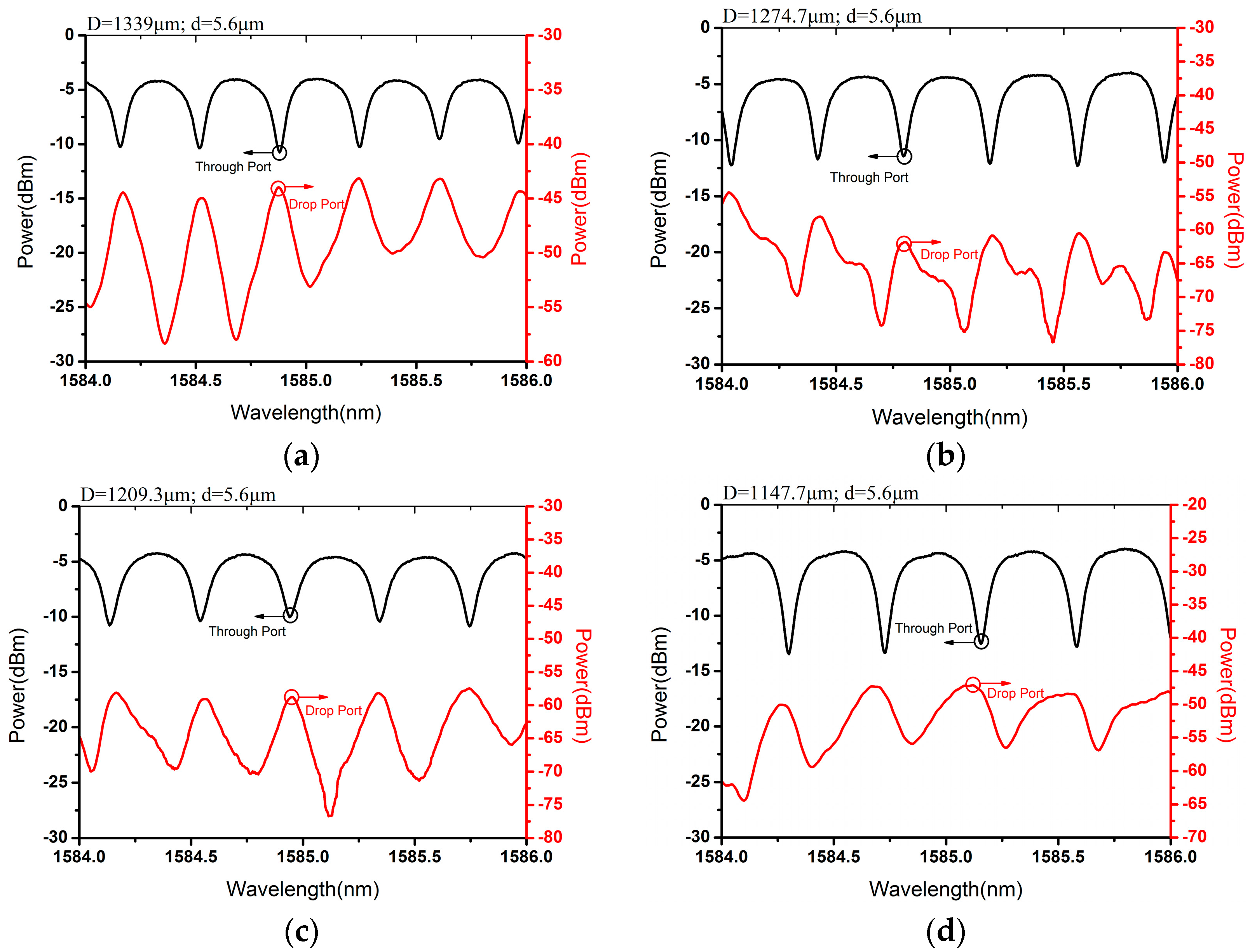
2.1. Drop Functionality and Its Performance Dependence on Microfiber Knot Ring Diameter

The measured transmission spectra of the drop filter with different diameters of the MKR are shown (Figure 2). They were measured from the drop port (in red) and through port (in black) by an optical spectral analyzer (OSA) when light was launched into the filter at the input port by a tunable laser source (TLS) ranging from 1520 nm to 1620 nm. To investigate the relative relationship between the spectra of different ports, their spectra were put in the same wavelength range from 1584 nm to 1586 nm. The diameters of the microfiber knot ring were, respectively, ~1339.0 μm (Figure 2a), ~1274.7 μm (Figure 2b), ~1209.3 μm (Figure 2c) and ~1147.7 μm (Figure 2d).
When the transmitted light satisfied the constructive interference condition, it oscillated to reach its maximum optical power in the MKR [12,15]. However, the non-resonant light would transmit through the MKR with relatively low loss. Therefore, black resonant curves will show as valleys at resonant wavelength. When the light propagates in the MKR, it will be coupled into the LN microwaveguide because the effective refractive index of the fiber is lower than that of the LN waveguide (1.468 versus 2.154). As a result, the red resonant curves will show as peaks at the resonant wavelength, corresponding with the valleys in black resonant curves. Additionally, they can be regarded as the resonant characteristics of the drop filter. In other words, only the resonant light can transmit through the microfiber knot ring towards on the drop port while the non-resonant light would be filtered. The irregular fluctuation of the spectra in red may be caused by scattered light.
When the diameters of the MKR were 1339.0 μm, 1274.7 μm, 1209.3 μm, and 1147.7 μm, the measured average optical power at the drop port was −49.1 dBm, −65.4 dBm, −64.6 dBm, and −52.5 dBm, respectively, while the extinction ratio of the drop port was, respectively, 14.0 dB, 12.4 dB, 11.6 dB, and 8.8 dB, which are larger than those of the through port (Figure 2). The coupling efficiency can be further improved by using the method as Latawiec et al. reported [26]. Moreover, with the decrease of the ring diameter, the FSR increased from 0.365 nm to 0.38 nm, 0.405 nm, and 0.43 nm, correspondingly.

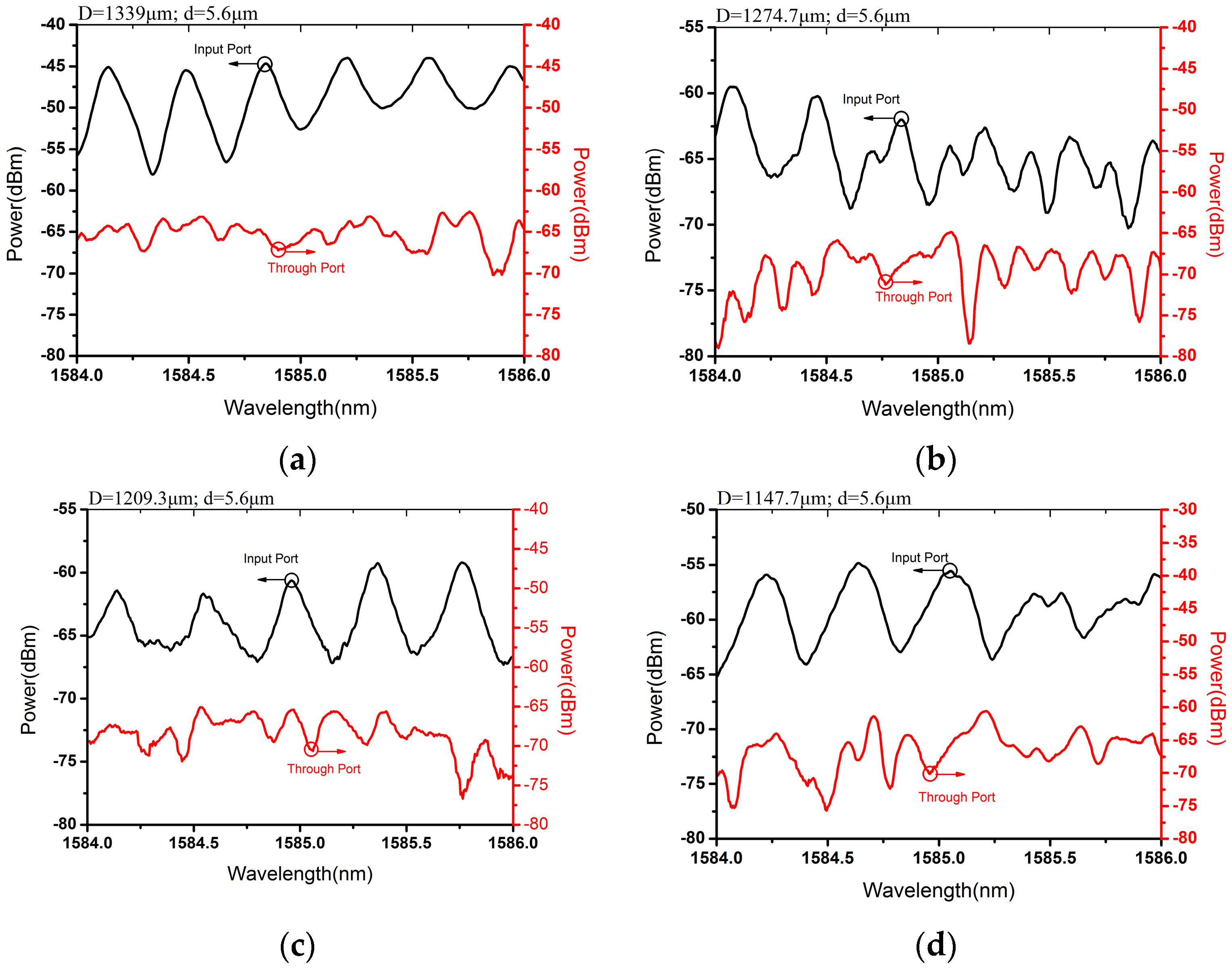
2.2. Add Functionality and Its Performance Dependence on Microfiber Knot Ring Diameter

The add functionality was demonstrated by evaluating the optical spectral characteristics of the add filter, and light was launched into the add port by the standard single-mode fiber. The transmission spectra were measured at the input port and through port under the same experimental condition as the drop functionality experiments. Besides, they were marked and shown in the same way as in the drop functionality (Figure 3). Wavelength-dependent resonance behaviors were observed at the input port. However, no resonance behavior was observed at the through port. The detected optical power at the through port was quite low so the scattered light was directly coupled into the through port. With the diameter of the MKR at 1339 μm, 1274.7 μm, 1209.3 μm, and 1147.7 μm, the extinction ratio of the input port is 11.9 dB, 6.7 dB, 6.4 dB, and 7.4 dB, respectively. Besides, the FSR of the transmission spectra also increased with the decrease of the ring diameter.

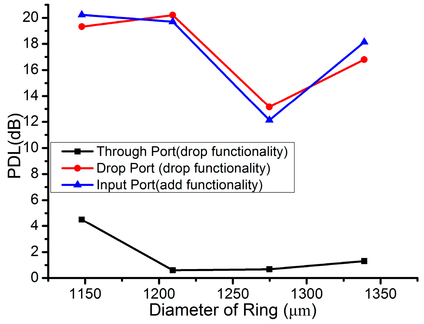
2.3. Polarization-Dependent Loss

The polarization-dependent loss (PDL) from the through port, drop port (drop filter) and input port (add filter) was also measured as illustrated in Figure 4. The 1550 nm laser launched from the TLS was firstly coupled into the polarization controller. We adjusted the polarization controller to achieve all of the possible polarization states of the transmitted light before coupling into the input port or add port. The optical power of the transmitted light was monitored (in dBm) by the power detector at different ports. The PDL (in dB) was obtained by subtracting the minimum optical power from the maximum one. When light was injected from the input port to the drop port at the drop filter or from the add port to the input port at the add filter, the light was transmitted straight through the LN APE microwaveguide. Since the APE waveguide was fabricated in X-Cut LN with the propagation direction of the Y axis, it supports the TE polarization [27,28,29,30]. Hence, the measured PDL from the drop port and input port is much larger than that from the through port of the drop filter.

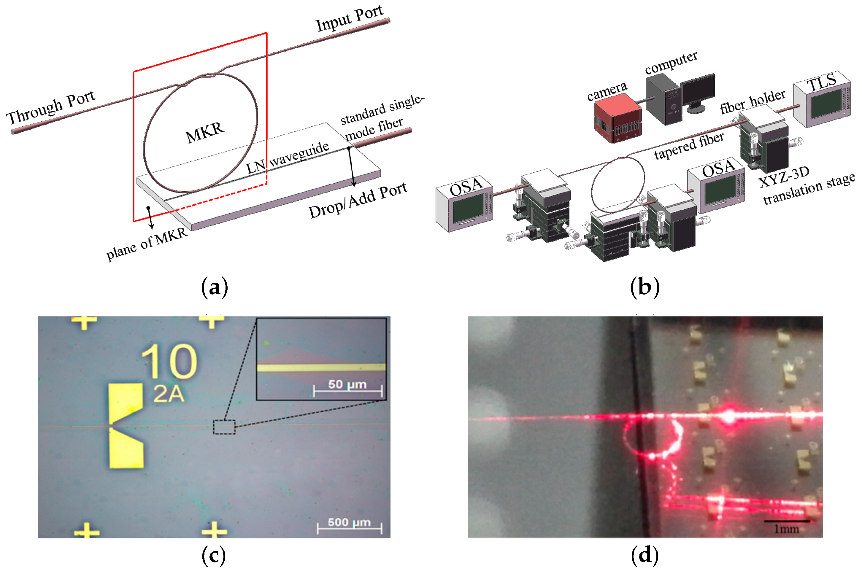
3. Materials and Methods

3.1. Fabrication of Microfiber Knot Ring

Firstly, a standard single-mode fiber was heated by alcohol burner with its coating peeled. Secondly, we elongated the fiber until a desired diameter and length (~5 cm). Thirdly, the microfiber was knotted into a large ring with its diameter of ~3 cm. Later, the MKR was carefully held by fiber holders fixed in two translation stages. Finally, we pulled the freestanding ends of two unheated fibers or moved the translation stages in opposite directions slowly to decrease the microfiber knot ring.

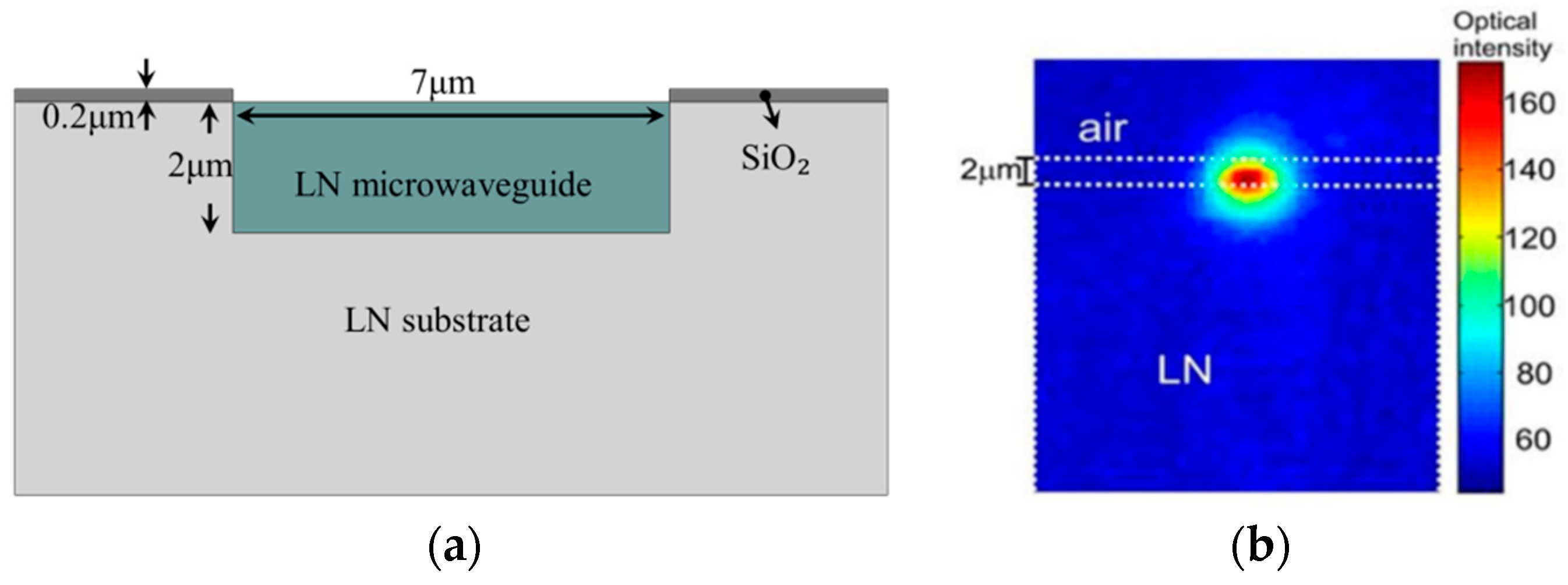
3.2. Lithium Niobate Microwaveguide

The LN APE waveguide chip we used is of 14.5 mm both for the length and the width. The LN APE waveguides, 14.5 mm in length, 7 μm in width and 2 μm in APE depth, are exposed to air. A layer of silica with a depth of 0.2 μm was deposited on the LN substrate (Figure 5a). The guided mode profile (experimental output) of the Gaussian beam with its full width at half maximum (FWHM) of ~5 μm and height (FWHM) of ~2.5 μm is also shown in LN APE waveguide (Figure 5b).

3.3. Coupling Process of Experiment

After the fabrication of the MKR, we twisted the freestanding ends of two unheated fibers to force the plane of the MKR vertically (Figure 1a). Then, the microwaveguide chip was placed on a high precision XYZ three-dimensional translation stage. Afterward, we adjusted the translation stage to make sure that the LN APE microwaveguide was in the plane of the MKR. Later, we made the LN microwaveguide contact with the MKR by moving up the translation stage. During the coupling process, a stereo-microscope equipped with camera connected to a personal computer was utilized for visualization.

4. Conclusions

In conclusion, we fabricated a microfiber with a diameter of 5.6 μm and knotted it into a MKR with a ring diameter of 1339.0 μm, and a quality factor of 26415. We loaded the MKR on the LN microwaveguide to construct a new add-drop filter. The filter reported here shows the wavelength dependence characteristics in both drop and add functionalities and the behaviors of the add-drop filter can be observed. The MKR can also be connected to the traditional optical fiber systems at low loss, while the LN microwaveguide can provide excellent optical properties such as a larger electro-optic coefficient and nonlinear optical properties. As a result, the device that was experimentally demonstrated may provide an alternative way to realize an optical interconnection between the fiber-optic micro- and nano-device and microstructured chip.

Acknowledgments

This work is supported by National Natural Science Foundation of China (No. 61405075; 61177075; 61275046; 61361166006; 61475066; 61505069; 61575084; 61401176), the Guangdong Natural Science Funds for Distinguish Young Scholar (2015A030306046), the Natural Science Foundation of Guangdong Province (No. 2014A030313377, 2014A030310205, 2015A030313320), the Core Technology Project of Strategic Emerging Industries of Guangdong Province (2012A032300016), Special Funds for major science and technology projects of Guangdong Province (2014B010120002, 2014B010117002, 2015B010125007), Special Funds for Discipline Construction of Guangdong Province (2013CXZDA005), Planned Science and Technology Project of Guangzhou under Grant (201506010046), Excellent Young Teachers Program of Guangdong High Education (YQ2015018).

Author Contributions

Huihui Lu conceived and designed the experiments; Suxu Zhou performed the experiments; Suxu Zhou, Yuan Wang, Donghui He and Yang Hu analyzed the data; Jianhui Yu, Heyuan Guan, Jun Zhang, Yunhan Luo and Jieyuan Tang contributed analysis tools; Zhe Chen supervised the process of the experiment; Huihui Lu and Suxu Zhou wrote the paper.

Conflicts of Interest

The authors declare no conflict of interest.

Abbreviations

The following abbreviations are used in this manuscript:
LN
lithium niobate
MKR
microfiber knot ring
MNOF
micro/nano optical fiber
APE
annealed proton exchange
FSR
free spectral range
PDL
polarization dependent loss
OSA
optical spectral analyzer
TLS
tunable laser source

References

  1. Tong, L.M.; Gattass, R.R.; Ashcom, J.B.; He, S.L.; Lou, J.Y.; Shen, M.Y.; Maxwell, I.; Mazur, E. Subwavelength-diameter silica wires for low-loss optical wave guiding. Nature 2003, 426, 816–819. [Google Scholar] [CrossRef] [PubMed]
  2. Jiang, X.S.; Yang, Q.; Vienne, G.; Li, Y.H.; Tong, L.M.; Zhang, J.J.; Hu, L.L. Demonstration of microfiber knot laser. Appl. Phys. Lett. 2006, 89, 143513. [Google Scholar] [CrossRef]
  3. Jiang, X.S.; Song, Q.H.; Xu, L.; Fu, J.; Tong, L.M. Microfiber knot dye laser based on the evanescent-wave-coupled gain. Appl. Phys. Lett. 2007, 90, 233501. [Google Scholar] [CrossRef]
  4. Arjmand, M.; Ahmadi, V.; Karimi, M. Wavelength-selective optical amplifier based on microfiber coil resonators. J. Lightwave Technol. 2012, 30, 2596–2602. [Google Scholar] [CrossRef]
  5. Yuhang, L.; Limin, T. Mach-zehnder interferometers assembled with optical microfibers or nanofibers. Opt. Lett. 2008, 33, 303–305. [Google Scholar]
  6. Sulaiman, A.; Harun, S.W.; Ahmad, F.; Muhammad, M.Z.; Jasim, A.A.; Ahmad, H. Demonstration of microfiber hybrid mach–zehnder and knot resonator structure. Microwave Opt. Technol. Lett. 2013, 55, 100–102. [Google Scholar] [CrossRef]
  7. Wu, Y.; Rao, Y.J.; Chen, Y.H.; Gong, Y. Miniature fiber-optic temperature sensors based on silica/polymer microfiber knot resonators. Opt. Express 2009, 17, 18142–18147. [Google Scholar] [CrossRef] [PubMed]
  8. Sumetsky, M. Optical fiber microcoil resonators. Opt. Express 2004, 12, 2303–2316. [Google Scholar] [CrossRef] [PubMed]
  9. Sumetsky, M. Basic elements for microfiber photonics: Micro/nanofibers and microfiber coil resonators. J. Lightwave Technol. 2008, 26, 21–27. [Google Scholar] [CrossRef]
  10. Sumetsky, M.; Dulashko, Y.; Fini, J.M.; Hale, A. Optical microfiber loop resonator. Appl. Phys. Lett. 2005, 86, 161108. [Google Scholar] [CrossRef]
  11. Sumetsky, M.; Dulashko, Y.; Fini, J.M.; Hale, A.; DiGiovanni, D.J. The microfiber loop resonator: Theory, experiment, and application. J. Lightwave Technol. 2006, 24, 242–250. [Google Scholar] [CrossRef]
  12. Jiang, X.S.; Tong, L.M.; Vienne, G.; Guo, X.; Tsao, A.; Yang, Q.; Yang, D.R. Demonstration of optical microfiber knot resonators. Appl. Phys. Lett. 2006, 88, 223501. [Google Scholar] [CrossRef]
  13. Xiao, L.M.; Birks, T.A. High finesse microfiber knot resonators made from double-ended tapered fibers. Opt. Lett. 2011, 36, 1098–1100. [Google Scholar] [CrossRef] [PubMed]
  14. Jiang, X.D.; Chen, Y.; Vienne, G.; Tong, L.M. All-fiber add-drop filters based on microfiber knot resonators. Opt. Lett. 2007, 32, 1710–1712. [Google Scholar] [CrossRef] [PubMed]
  15. Yu, J.H.; Jin, S.S.; Wei, Q.S.; Zang, Z.G.; Lu, H.H.; He, X.L.; Luo, Y.H.; Tang, J.Y.; Zhang, J.; Chen, Z. Hybrid optical fiber add-drop filter based on wavelength dependent light coupling between micro/nano fiber ring and side-polished fiber. Sci. Rep. 2015, 5, 7710. [Google Scholar] [CrossRef] [PubMed]
  16. Lu, H.H.; Sadani, B.; Ulliac, G.; Guyot, C.; Courjal, N.; Collet, M.; Baida, F.I.; Bernal, M.P. Integrated temperature sensor based on an enhanced pyroelectric photonic crystal. Opt. Express 2013, 21, 16311–16318. [Google Scholar] [CrossRef] [PubMed]
  17. Yim, Y.S.; Shin, S.Y. Lithium niobate integrated-optic voltage sensor with variable sensing ranges. Opt. Commun. 1998, 152, 225–228. [Google Scholar] [CrossRef]
  18. Becker, R.A. Comparison of guided-wave interferometric modulators fabricated on linbo3 via Ti indiffusion and proton exchange. Appl. Phys. Lett. 1983, 43, 131–133. [Google Scholar] [CrossRef]
  19. Fukunishi, S.; Uchida, N.; Miyazawa, S.; Noda, J. Electro-optic modulation of optical guided wave in linbo 3 thin film fabricated by egm method. Appl. Phys. Lett. 1974, 24, 424–426. [Google Scholar] [CrossRef]
  20. Wooten, E.L.; Kissa, K.M.; Yi-Yan, A.; Murphy, E.J.; Lafaw, D.A.; Hallemeier, P.F.; Maack, D.; Attanasio, D.V.; Fritz, D.J.; McBrien, G.J.; et al. A review of lithium niobate modulators for fiber-optic communications systems. IEEE J. Sel. Top. Quantum Electron. 2000, 6, 69–82. [Google Scholar] [CrossRef]
  21. Lu, H.H.; Qiu, W.T.; Guyot, C.; Ulliac, G.; Merolla, J.M.; Baida, F.; Bernal, M.P. Optical and RF characterization of a lithium niobate photonic crystal modulator. IEEE Photon. Technol. Lett. 2014, 26, 1332–1335. [Google Scholar] [CrossRef]
  22. Wu, X.X.; Peng, W.R.; Arbab, V.; Wang, J.; Willner, A. Tunable optical wavelength conversion of OFDM signal using a periodically-poled lithium niobate waveguide. Opt. Express 2009, 17, 9177–9182. [Google Scholar] [CrossRef] [PubMed]
  23. Lee, Y.W.; Fan, F.C.; Huang, Y.C.; Gu, B.Y.; Dong, B.Z.; Chou, M.H. Nonlinear multiwavelength conversion based on an aperiodic optical superlattice in lithium niobate. Opt. Lett. 2002, 27, 2191–2193. [Google Scholar] [CrossRef] [PubMed]
  24. Guarino, A.; Poberaj, G.; Rezzonico, D.; Degl’Innocenti, R.; Gunter, P. Electro-optically tunable microring resonators in lithium niobate. Nat. Photon. 2007, 1, 407–410. [Google Scholar] [CrossRef]
  25. Wang, C.; Burek, M.J.; Lin, Z.; Atikian, H.A.; Venkataraman, V.; Huang, I.C.; Stark, P.; Loncar, M. Integrated high quality factor lithium niobate microdisk resonators. Opt. Express 2014, 22, 30924–30933. [Google Scholar] [CrossRef] [PubMed]
  26. Latawiec, P.; Burek, M.J.; Venkataraman, V.; Lončar, M. Waveguide-loaded silica fibers for coupling to high-index micro-resonators. Appl. Phys. Lett. 2015, 108, 031103. [Google Scholar] [CrossRef]
  27. Lu, H.; Sadani, B.; Ulliac, G.; Courjal, N.; Guyot, C.; Merolla, J.M.; Collet, M.; Baida, F.I.; Bernal, M.P. 6-micron interaction length electro-optic modulation based on lithium niobate photonic crystal cavity. Opt. Express 2012, 20, 20884–20893. [Google Scholar] [CrossRef] [PubMed]
  28. Lu, H.; Sadani, B.; Courjal, N.; Ulliac, G.; Smith, N.; Stenger, V.; Collet, M.; Baida, F.I.; Bernal, M.P. Enhanced electro-optical lithium niobate photonic crystal wire waveguide on a smart-cut thin film. Opt. Express 2012, 20, 2974–2981. [Google Scholar] [CrossRef] [PubMed]
  29. Lu, H.; Issam Baida, F.; Ulliac, G.; Courjal, N.g.; Collet, M.; Bernal, M.-P. Lithium niobate photonic crystal wire cavity: Realization of a compact electro-optically tunable filter. Appl. Phys. Lett. 2012, 101, 151117. [Google Scholar] [CrossRef]
  30. Wang, Y.; Chen, Z.; Zhou, S.; Yu, J.; Zeng, Y.; Luo, Y.; Zhang, J.; Tang, J.; Guan, H.; Lu, H. Theoretical analysis of optical mode deflection in lithium niobate waveguide with serrated array electrodes. Opt. Quantum Electron. 2016, 48, 162. [Google Scholar] [CrossRef]
Figure 1. Schematic diagram of the add-drop filter and its experimental setup. (a) Schematic diagram of the add-drop filter based on light coupling between a MKR with a lithium-niobate microwaveguide chip; (b) Schematic diagram of the experimental setup of the drop filter; (c) Photograph of the lithium-niobate microwaveguide chip and its enlarged view; (d) Photograph of MKR optically coupled with the lithium niobate microwaveguide with a diameter of ~1274.7 μm.
Crystals 06 00067 g001
Figure 2. Experimental transmission spectra of the drop filter with different ring diameters of 1339.0 μm (a); 1274.7 μm (b); 1209.3 μm (c) and 1147.7 μm (d), respectively.
Crystals 06 00067 g002
Figure 3. Experimental transmission spectra of the add filter with different ring diameters of 1339.0 μm (a); 1274.7 μm (b); 1209.3 μm (c); and 1147.7 μm (d), respectively.
Crystals 06 00067 g003
Figure 4. Polarization-dependent loss measured from through port, drop port (drop filter) and input port (add filter).
Crystals 06 00067 g004
Figure 5. (a) Schematic diagram of sectional view of lithium-niobate chip; (b) Optical mode profile of LN waveguide.
Crystals 06 00067 g005

