Article

Broadband Transmission Loss Using the Overlap of Resonances in 3D Sonic Crystals

by
Alexandre Lardeau
1,
Jean-Philippe Groby
2 and
Vicente Romero-García
2,*
1
Laboratoire DRIVE-ISAT, 49 rue Mademoiselle Bourgeois, 58027 Nevers Cedex, France
2
Laboratoire d’Acoustique de l’Université du Maine, Avenue Olivier Messiaen, Cedex 9, 72085 Le Mans, France
*
Author to whom correspondence should be addressed.
Crystals 2016, 6(5), 51; https://doi.org/10.3390/cryst6050051
Submission received: 25 March 2016 / Revised: 25 April 2016 / Accepted: 3 May 2016 / Published: 11 May 2016
(This article belongs to the Special Issue Phononic Crystals)

Abstract

:
The acoustic properties of a three-dimensional sonic crystal made of square-rod rigid scatterers incorporating a periodic arrangement of quarter wavelength resonators are theoretically and experimentally reported in this work. The periodicity of the system produces Bragg band gaps that can be tuned in frequency by modifying the orientation of the square-rod scatterers with respect to the incident wave. In addition, the quarter wavelength resonators introduce resonant band gaps that can be tuned by coupling the neighbor resonators. Bragg and resonant band gaps can overlap allowing the wave propagation control inside the periodic resonant medium. In particular, we show theoretically and experimentally that this system can produce a broad frequency band gap exceeding two and a half octaves (from 590 Hz to 3220 Hz) with transmission lower than 3%. Finite element methods were used to calculate the dispersion relation of the locally resonant system. The visco-thermal losses were accounted for in the quarter wavelength resonators to simulate the wave propagation in the semi-infinite structures and to compare the numerical results with the experiments performed in an echo-free chamber. The simulations and the experimental results are in good agreement. This work motivates interesting applications of this system as acoustic audible filters.
PACS:
43.20-f; 43.20.Fn; 43.20.El

Graphical Abstract

1. Introduction

Periodic arrays of rigid scatterers embedded in a fluid are the analogues for the acoustic waves of the crystalline structures for the electrons or the photonic crystals for the electromagnetic waves. Such structures are known as Sonic Crystals (SCs) [1] and the exploitation of the periodic distribution of scatterers in such structures have been intensively used to control the acoustic wave propagation. Perhaps the most known property of such systems is the presence of band gaps, ranges of frequencies in which the wave propagation is forbidden. The band gaps appear at high symmetry points in the Brillouin zone due to the presence of a degeneracy of the band structure produced by the Bragg interferences in the diffractive regime ( λ a / 2 , λ being the wavelength of the incident wave and a the lattice constant characterizing the periodicity of the structure). Many interesting physical phenomena arise from this particular dispersion relation such as wave localization [2,3], excitation of evanescent waves [4,5], and relevant applications concerns filtering [6] and wave guiding [7,8,9]. In particular, many approaches have been proposed to degenerate the band and thus enlarge the band gaps [10,11,12]. Some possibilities consist of either reducing the total symmetry of the crystal in order to remove some band degeneracies, allowing the appearance of complete gaps [13] or optimizing the shape and arrangement of the scatterers [14,15,16,17,18]. The dispersion relation is governed particularly by both the periodicity and the shape of the scatterers providing different tools to tune the wave propagation.
Interesting properties can be obtained in the low frequency regime ( λ a ) in periodic structures if local resonators are used as scatterers. In acoustics, the pioneering works of Bradley [19] and Sugimoto [20] theoretically and experimentally examined the propagation of sound waves in a waveguide loaded periodically with local resonators (quarter wavelength and Helmholtz resonators). In these systems two different mechanisms are responsible of the generation of band gaps. The Bragg interferences produce the band gap due to the periodicity, while the resonances produce other band gaps when the frequency of sound waves coincides with the natural frequency of the resonators. The latter induces an hybridization between the resonance and the dispersion of the non resonant periodic structure. This feature has been used to introduce the concept of acoustic metamaterials with resonant band gaps at lower frequencies than the Bragg band gap [21,22,23], as well as to improve the absorption capabilities of porous materials in the low frequency regime [24].
In this article we exploit the idea of the coupling of the local resonant scatterers to generate multiple resonances that can be combined with the effect of periodicity in order to produce a broadband frequency region with high transmission loss. We experimentally and theoretically study the propagation properties of a three-dimensional SC made of square cross-section rod rigid scatterers incorporating a periodic arrangement of quarter wavelength resonators of circular cross-section. Particularly, we analyze different configurations in which the coupling between the resonators in the structure generates multiple resonances that are designed to be close to the Bragg band gap. This combined effect produces an overlap of the stop bands that can be used to strongly reduce the transmission in a broadband range of frequencies. In particular, we experimentally and theoretically show that the system can produce a broad frequency band gap exceeding two and a half octaves (from 590 Hz to 3220 Hz) with transmission lower than 3% in this whole frequency range. Finite element methods are used to study the dispersion relation of the locally resonant system. The visco-thermal losses are accounted for in the quarter wavelength resonators to study the wave propagation in the semi-infinite structures and to compare numerical results with the experimental ones performed in an echo-free chamber.

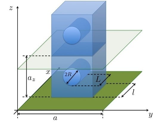
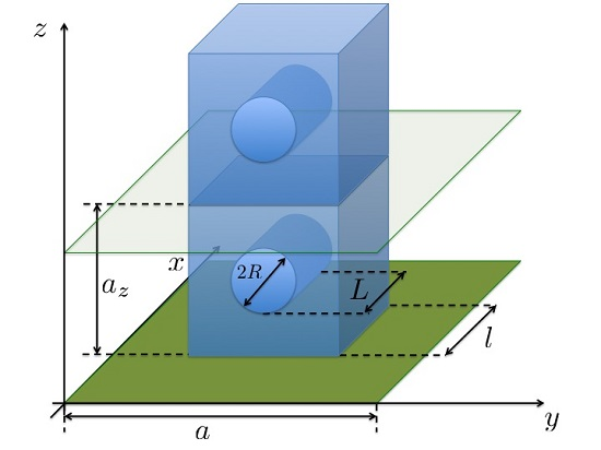
2. Experimental Set-Up

The resonant scatterers are infinitely long square-rod scatterers made of exotic wood (acoustically rigid for the ranges of frequencies analyzed in this work) with side length l. Each scatterer incorporates a 1D periodic array of quarter wavelength resonators with periodicity a z . These quarter wavelength resonators are made by drilling cylindrical holes of radius R and length L in one of the faces of the square-rod scatterer. The resonant square-rod scatterers are placed in a square array of periodicity a. Figure 1a shows the scheme of a resonant square-rod scatterer showing the parameters of the basic unit cell of the crystalline structure analyzed in this work. Figure 1b shows the scheme of the finite array analyzed in this work as well as a picture of the SC in the anechoic chamber. As shown in the inset of the Figure 1b the unit cell can be rotated by an angle θ with respect to the center of the resonant square-rod scatterer, adding a degree of freedom to tune the dispersion relation of the system.
The experimental prototype consists of a 16 × 6 array, located on a square lattice with constant a = 7 . 5 cm with a vertical periodicity of the quarter wavelength of a z = 5 cm. The scatterers have a side length l = 5 cm. The quarter wavelength resonator has a diameter of 2 R = 3 . 5 cm and length L = 4 cm. Finally, the scatterers are 2 m long and incorporate 29 quarter wavelength resonators in their central parts.
All the acoustic measurements are performed using a microphone B&K 1/4” type 4135 (B&K, Naerum, Denmark). The acoustic source was the loudspeaker Genelec 8351A (Genelec, Olivitie, Finland). The movement of the microphone in the anechoic chamber is controlled by a 1D robotized arm (Zaber LSQ, Vancouver, Canada) designed to move the microphone over a 1D trajectory with a step of 1 cm. The acquisition of the acoustic signal is preformed using a Stanford SR 785 analyzer (Stanford Research Systems, Inc., Sunnyvale, USA). The movement of the robotized arm and the acquisition are synchronized by a computer. Once the robotized system has positioned the microphone, the acoustic source generates a swept sine signal and the microphone detects it. The analyzer provides the frequency domain signals (module and phase for each frequency).
In the approach considered here, the loudspeaker used to generate the acoustic field in the anechoic chamber is placed in x s = 0 and a single microphone was used to measure the transfer functions between the signal provided to the loudspeaker and the sound pressure at four locations shown in Figure 1b. The loudspeaker and the microphone are aligned in the middle height of the structure and only propagation in the x - y plan, i.e., along the Γ X M Γ is considered. Those transfer functions are denoted P 1 to P 4 . The wave front can be considered planar because the loudspeaker is placed far enough from the SC although it produces a spherical wave front. However, the amplitude decay of the wave is considered as 1 / x i where x i is the distance between the loudspeaker and the i-th location of the microphone. For the present purposes P 1 to P 4 may be considered to represent the complex sound pressure at the four measurement locations x 1 to x 4 , i.e.,
P 1 = A e - ı k x 1 x 1 + B e ı k x 1 x 1 , P 2 = A e - ı k x 2 x 2 + B e ı k x 2 x 2 , P 3 = C e - ı k x 3 x 3 + D e ı k x 3 x 3 , P 4 = C e - ı k x 4 x 4 + D e ı k x 4 x 4 .
Here, k represents the wavenumber in the ambient fluid and e + ı ω t sign convention has been adopted ( ω = 2 π f is the angular frequency with f the frequency). The four complex pressures, P 1 to P 4 , comprise various superpositions of positive- and negative-going waves in the up- and downstream segments of the anechoic chamber. In the range of frequencies of interest in this work, f a / c 1 , only the fundamental grating plane mode is reflected back (specular reflection), so the reflected waves can be approximated as plane waves. The higher grating order modes are evanescent and their amplitudes decay rapidly away from the SC so that they disappear in the vicinity of the SC. The complex amplitudes of those waves are represented by the coefficients A to D. Equation (1) yield four equations for the coefficients A to D in terms of the four measured sound pressures, i.e.,
A = ı ( x 1 P 1 e ı k x 2 - x 2 P 2 e ı k x 1 ) 2 sin ( k ( x 1 - x 2 ) ) , B = ı ( x 2 P 2 e - ı k x 1 - x 1 P 1 e - ı k x 2 ) 2 sin ( k ( x 1 - x 2 ) ) , C = ı ( x 3 P 3 e ı k x 4 - x 4 P 4 e ı k x 3 ) 2 sin ( k ( x 3 - x 4 ) ) , D = ı ( x 4 P 4 e - ı k x 3 - x 3 P 3 e - ı k x 4 ) 2 sin ( k ( x 3 - x 4 ) ) .
The latter coefficients provide the input data for subsequent transfer matrix calculations. Here, the transfer matrix is used to relate the sound pressures and normal acoustic particle velocities on the two faces of the SC respectively located at x 0 and x d as in Figure 1b, i.e.,
P V x 0 = T 11 T 12 T 21 T 22 P V x d .
In Equation (3), P is the exterior sound pressure and V is the exterior normal acoustic particle velocity. The pressures and particle velocities on the two opposite surfaces of the SC may easily be expressed in terms of the positive- and negative-going wave component amplitudes, i.e.,
P ( x 0 ) = 1 x 0 A e - ı k x 0 + B e ı k x 0 , V ( x 0 ) = 1 x 0 A e - ı k x 0 - B e ı k x 0 ρ c , P ( x d ) = 1 x d C e - ı k x d + D e ı k x d , V ( x d ) = 1 x d C e - ı k x d - D e ı k x d ρ c .
where ρ is the ambient fluid density and c is the ambient sound speed. Thus, when the plane wave components are known from measurements of the complex pressures at the four locations, the pressures and the normal particle velocities at the two opposite surfaces of the SC can be determined.
It is then of interest to determine the elements of the transfer matrix since, as will be shown below, the elements of that matrix may be directly related to the properties of the SC. Then, instead of making a second set of measurements it is possible to assume the reciprocal nature of the SC. Thus, given reciprocity and symmetry, it follows that
(5) T 11 = T 22 , (6) T 11 T 22 - T 12 T 21 = 1 .
The transfer matrix elements can be expressed directly in terms of the pressures and velocities on the two opposite surfaces of the SC. Therefore, if the transmission coefficient is defined as T = C / A , and if we consider anechoic termination, i.e., D = 0 , it can be expressed in function of the elements of the transfer matrix
T = 2 x d e ı k ( x d - x 0 ) ( x 0 ( T 11 + T 12 / ( ρ c ) + ( ρ c ) T 21 + T 22 ) ) .
In what follows, we will focus on the transmission coefficient, all the configurations not being necessarily symmetric. In particular, the configuration depicted in Figure 4 is reciprocal but not symmetric.

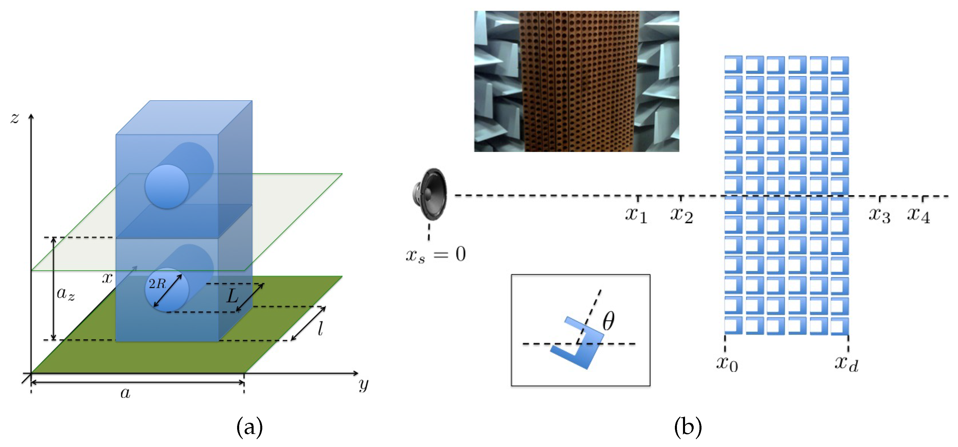
3. Numerical Characterization

Due to the complexity of the geometry of the resonant square-rod scatterers Finite Elements Method (FEM) is chosen to solve both the eigenvalue and the scattering problems. Therefore it is necessary to define the symmetry, discretize the domain and consider the boundary conditions for each configuration. In the following subsections we will give the details for each configuration. In a general way, we discretize the domains at least with 10 points for the minimal analyzed wavelength, λ m i n . The study has been performed only along the Γ X M Γ direction and in a range of normalized frequencies, f a / c , from 0 to 0.8, therefore λ m i n = 0 . 8 a .

3.1. Eigenvalue Problem

The eigenvalue problem is solved to obtain the dispersion relation of the periodic medium. The problem ω ( k ) is solved using only the unit cell of the crystal and applying the Floquet-Bloch periodic conditions. The properties of the Bloch states constrain the solution to a unit cell with Bloch vectors in the first Brillouin zone. The unit cell is shown in Figure 1a. Neumann boundary conditions, representing rigid walls, are considered on the walls of the scatterer. At the interface between the quarter wavelength resonator and the surrounding medium the continuity of the pressure and normal acoustical particle velocity are imposed. By fixing the wavevector, k, in the irreducible Brillouin zone of the unit cell we can obtain the eigenfrequencies for each wavevector. These features transform the unit cell in a bounded domain to solve the problem with the next boundary condition at the borders of the unit cell
p ( r + R ) = p ( r ) e ı k B · R ,
where R is the lattice vector and k B is the Bloch vector that scans the first irreducible Brillouin zone. For our configurations, the unit cell is a cubic one, therefore R = ( n a u x + m a u y + l a z u z ) . In this work we will not consider the effect in the z-direction, therefore we study the dispersion relation considering the variation of the k B x = [ 0 , π / a ] and k B y = [ 0 , π / a ] in the first irreducible zone of Brillouin of a cubic lattice having k B z = 0 .

3.2. Scattering Problem

Considering the wave propagation in free space (unbounded acoustic domain) no wave is assumed to be reflected from infinity. This is known as the Sommerfeld condition. The solutions of exterior Helmholtz problems that satisfy the Sommerfeld conditions are called radiating solutions. Using FEM it is only possible to obtain some approximation of the radiating solutions in unbounded domains by applying some artificial boundaries in the numerical domain. We use the perfectly matched layers (PML) technique for this purpose.
The geometry considered in this work is shown in Figure 2. We considered a semi-infinite slab made of N resonators along the x-direction; periodic boundary conditions are used in the y and z directions therefore the structure is infinite in y and z directions but finite in the x one. A plane wave impinges the structure from the negative x-axis and the PML condition is considered at the perpendicular parts of x-domain to numerically reproduce the Sommerfeld condition in this direction. The acoustic field will be evaluated in the y x -plane, crossing the unit cell in the middle of resonator.
The losses in the quarter wavelength resonators are accounted for by considering the Zwikker and Kosten model [25], which provides the expression for the equivalent density and bulk modulus in the cylindrical tube of radius R as,
(9) ρ e q = ρ 1 - 2 ( - ı ω / ν ) - 1 / 2 G R ( - ı ω / ν ) 1 / 2 / R - 1 , (10) K e q = γ P 0 1 - 2 ( γ - 1 ) ( - ı ω / ν ) - 1 / 2 G R ( - ı ω / ν ) 1 / 2 / R - 1 ,
where ν = 1 . 47 10 - 5 m 2 s - 1 is the kinematic viscosity of air, ω is the angular frequency of the wave, ν = 2 . 22 10 - 5 m 2 s - 1 is the thermal diffusivity of air, and the function G ( x ) is defined as,
G ( x ) = J 1 ( x ) J 0 ( x ) ,
where J n is the Bessel function of n - th order and first kind.

4. Results

Before studying the periodic structures, we start by analyzing the transmission through one row of resonant square-rod scatterer with θ = π / 2 . This will allow us to characterize the resonant frequency of the quarter wavelength resonator. Figure 3a shows the transmission coefficient, | T | 2 , for this system. Numerical simulations with and without losses in the resonators are plotted using continuous and dashed black lines respectively. Red open circles show the measured transmission coefficient. The minimum of transmission appears at the resonant frequency of the quarter wavelength resonators. In fact, if we numerically evaluate the acoustic pressure field at this frequency, f a / c = 0 . 3824 , we can observe (see Figure 3b) that the resonance is activated and that the acoustic field is localized inside the resonators. Notice that for this configuration the effect of the losses is not sensitive. However, we maintain the presence of losses because, this effect is not negligible when the number of scatterers and so of resonators increases, as we will see in the following subsections.

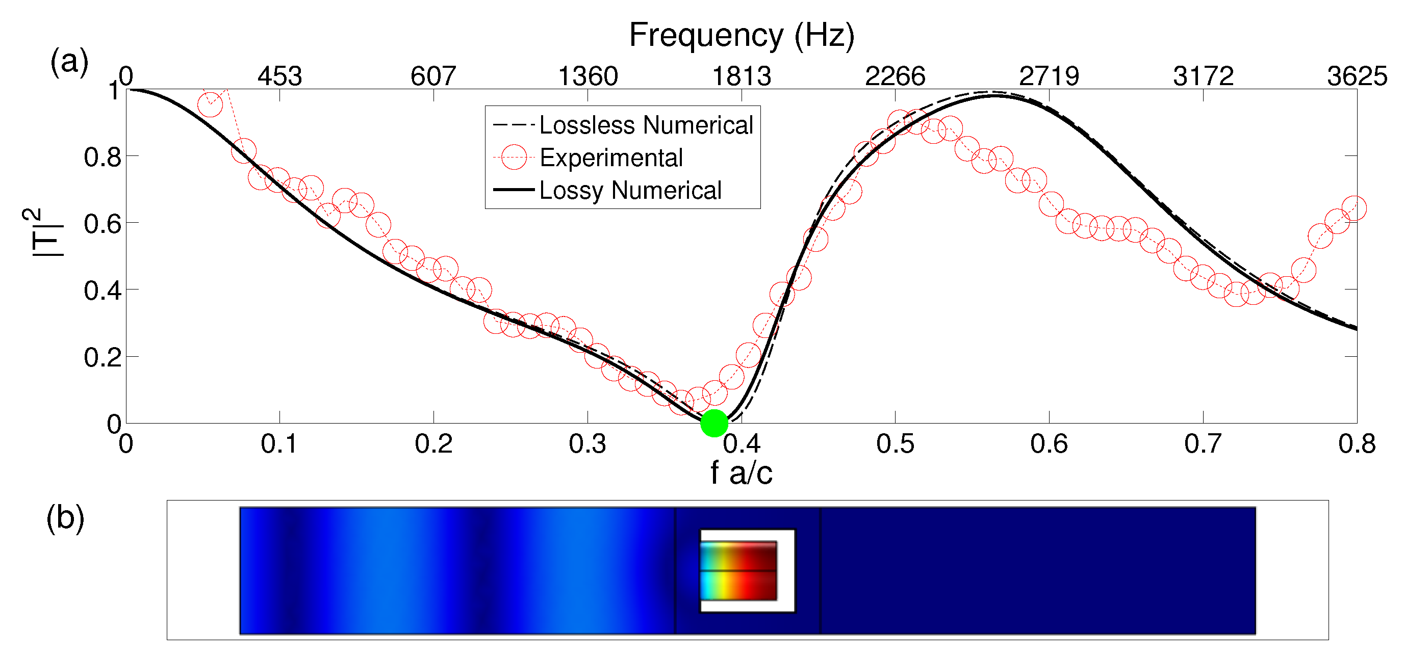
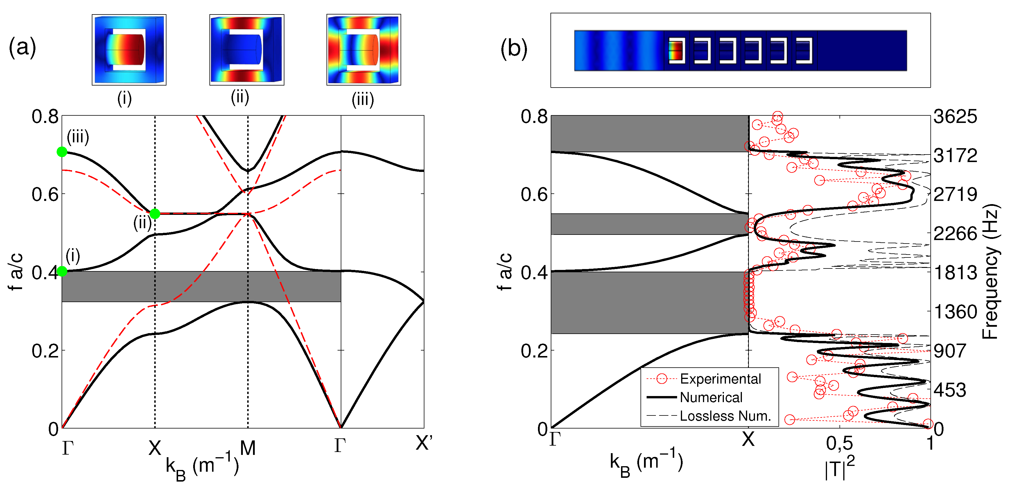
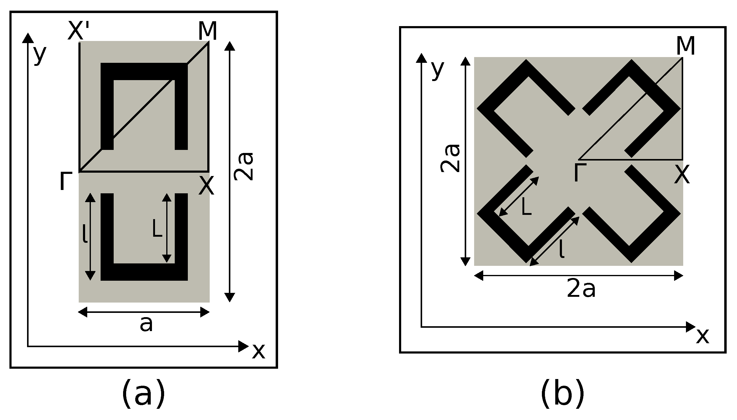
4.1. Single Resonant SC Made of Square-Rod Scatterers with Quarter Wavelengths Resonators

The dispersion relation numerically obtained for a SC made of resonant square-rods with θ = π / 2 is shown in Figure 4a with black lines. In order to compare with the non resonant case, we have represented the band structures for the same square-rods without the quarter wavelength resonators (red lines) [18]. While the non resonant structure does not present band gaps, the SC with the resonant square-rod scatterers presents a band gap (grey area in Figure 4a) around the resonant frequency of the quarter wavelength resonators, due to the hybridization of the resonance with the background medium.
If we pay attention to the Γ X direction, i.e., normal to the SC interface as it is plotted in Figure 1b three band gaps are present (see Figure 4b). The first one due to the hybridization band around the resonant frequency of the quarter wavelength resonators; the second one is produced by the Bragg interferences inside the SC due to the periodicity around f a / c = 0 . 5 ; and the third one is produced by the coupling of the second Bragg band gap and the second resonant mode of the resonators (see the eigenvector (iii) in Figure 4a).
The transmission coefficient is evaluated for a slab made of six rows of 16 resonant square-rod scatterers with θ = π / 2 . The results are plotted in the right panel of Figure 4b. The three stop bands are well recognized both numerically and experimentally in the transmission coefficient. We would like to notice here the effect of the losses due to the visco-thermal effect in the quarter wavelength resonators. The numerical transmission coefficient both with and without losses are plotted respectively in continuous line and dashed line. As predicted in previous works [26,27,28], the effect of losses is more important in the regions with high dispersion and small group velocity. In our problem, the values of the transmission coefficient with losses is reduced by a factor larger than 2 around these particular regions. From now on, all the numerical results concerning the transmission coefficient will be performed accounting for the losses.

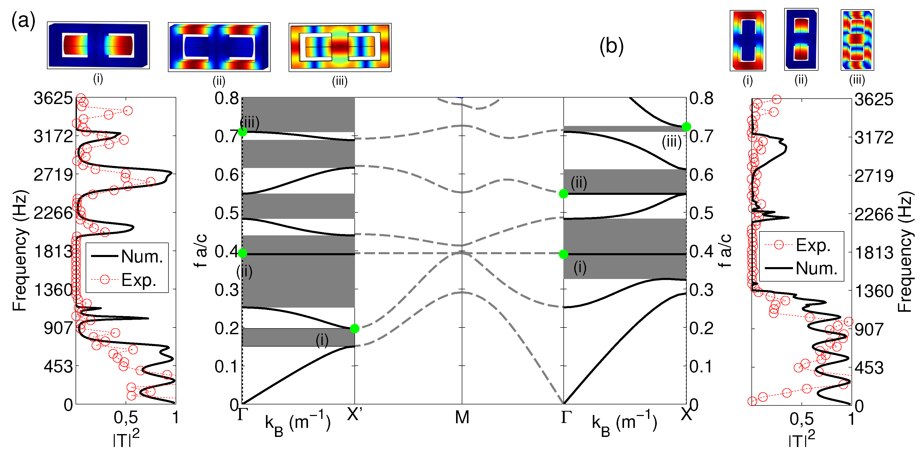
4.2. Multi-Resonant SC Made of Square-Rod Scatterers with Quarter Wavelengths Resonators

Using the degree of freedom offered by the possible rotation of the resonant scatterers around their principal axis, we can evaluate several configurations that exploit the coupling between the resonators to produce additional resonances in the range of frequencies of interest. These coupling introduce more band gaps in the dispersion relation and broaden the frequency range of low transmission through the structure. In this sense, we evaluate three different configurations. The first configurations consist of facing two neighbor resonant square-rod scatterers as shown in Figure 5a. In this kind of arrangement two different situations are possible: the first one when the incident direction is the Γ X (Conf. 1) and the second one when the incident wave follows the Γ X direction (Conf. 2). Finally, the third configuration (Conf. 3) consists of facing four different resonant square-rod scatterers as shown in Figure 5b.
Figure 6 shows the results for the configurations 1 and 2 with two resonant square-rod scatterers facing one with each other. Figure 6a represents the results for the case in which the incident wave is propagating along the Γ X direction (Conf. 1) while in the Figure 6b, the case in which the incident wave is propagating along the Γ X direction (Conf. 2) is analyzed. In both cases additional band gaps are opened due to the coupling between the resonators and the transmission is strongly reduced in these regions. In particular, six band gaps are opened in the Figure 6b. Both experimental and numerical transmission coefficients present deeps in transmission due to the presence of these band gaps. This configuration behaves like a strongly selective frequency filter.
Figure 7 shows the numerical predictions and experimental results for the configuration with four neighbor resonant square-rod scatterers facing one with each other (Conf. 3). Figure 7a shows the dispersion relation of such a periodic distribution. Seven band gaps are opened in this configuration. Different kind of phenomena are mixed in this system. On one hand, as in the previous structures, the periodicity opens band gaps due to Bragg interferences as for example the first and second band gaps around the eigenvector (i) (see the Figure 7b), and the resonances of quarter wavelength resonators open band gaps due to this resonance, for example around the frequency of the eigenvector (iv). However, the interest of such configuration is the coupling between the four scatterers. This opens resonant band gaps at frequencies different from those of an isolated quarter wavelength resonator. For example, band gaps around the frequencies of the eigenvectors (iii) and (v) result from coupling. This concentration of band gaps in the range of frequencies of interest can be used to produce a broad band of low transmission.
The transmission through a finite structure made of three unit cells of four faced resonant square-rod scatterers (total N = 6 resonant square-rod scatterers in the x-direction) is analyzed in the right panel of Figure 7a. In the numerical simulations (continuous line) we observe that the band gaps predicted by the eigenvalue problem are reproduced in the transmission. Moreover, the effect of the losses in the resonators destroys the transmission peaks that should be produced by the flat bands in the dispersion relation. As previously mentioned, the flat bands having a small group velocity and high dispersion, are strongly affected by the presence of losses in the system, destroying any propagation around these areas. Experimentally, the transmission coefficient also reproduces the band gaps predicted by these eigenvalue problem and is in agreement with the numerical evaluation of the transmission coefficient. The slight differences between the experimental results and the numerical ones, can be attributed to the presence of additional losses in the system, as for example those coming from the viscothermal losses between the walls of the resonant square-rod scatterers that are not considered in this work. Regarding the transmission of this system, we can see that the combined effect of periodicity and coupled resonators produces an overlap of the band gaps that can be used to strongly reduce the transmission in a broadband range of frequencies. In particular we experimentally and theoretically show that this last system can produce a broad frequency band gap exceeding two and a half octaves, from 590 Hz to 3220 Hz, with transmission lower than 3% in the whole range.

5. Conclusions

In this work, we use acoustic waves to experimentally prove the physical properties of modulated resonant systems made of resonant square-rod scatterers and to design broadband or selective filtering. Extensive simulations and experimental results in order to show tunable transmission properties of arrays made of resonant square-rod scatterers embedded in air are performed here. We have experimentally and theoretically shown that by rotating some of the resonant square-rod scatterers of a square array, one can easily activate the coupling between the resonators producing additional band gaps in the dispersion relation as well as modifying the Bragg interferences. The combined effect of the periodicity and the coupled resonances produces an overlap of the stop bands that can be used to strongly reduce the transmission in a broadband range of frequencies. In particular, we experimentally and theoretically show that the system can produce a broad frequency band gap exceeding two and a half octaves (from 590 Hz to 3220 Hz) with transmission lower than 3% in the whole range. This work could also be effectively extended to future realization of tunable systems for light, liquid, and other waves, which will lead to great potential in ultrasonics, for example. The tunability we demonstrated in this work could be applied to control not only the band gap but also other properties of the system.

Acknowledgments

This work has been funded by the Metaudible project ANR-13-BS09-0003, co-funded by ANR and FRAE.

Author Contributions

Vicente Romero-Garcia and Jean-Philippe Groby conceived the idea. Alexandre Lardeau performed the experiments and the numerical results. Alexandre Lardeau, Jean-Philippe Groby and Vicente Romero-Garcia participate in the discussions and writing the article.

Conflicts of Interest

The authors declare no conflict of interest. The founding sponsors had no role in the design of the study; in the collection, analyses, or interpretation of data; in the writing of the manuscript, and in the decision to publish the results.

References

  1. Martínez-Sala, R.; Sancho, J.; Sánchez, J.V.; Gómez, V.; Llinares, J.; Meseguer, F. Sound Attenuation by sculpture. Nature 1995, 378, 241. [Google Scholar] [CrossRef]
  2. Sigalas, M. Elastic wave band gaps and defect states in two-dimensional composites. J. Acoust. Soc. Am. 1997, 101, 1256–1261. [Google Scholar] [CrossRef]
  3. Li, X.; Liu, Z. Coupling of cavity modes and guiding modes in two-dimensional phononic crystals. Solid State Commun. 2005, 133, 397–402. [Google Scholar] [CrossRef]
  4. Laude, V.; Achaoui, Y.; Benchabane, S.; Khelif, A. Evanescent Bloch waves and the complex band structure of phononic crystals. Phys. Rev. B 2009, 80, 092301. [Google Scholar] [CrossRef]
  5. Romero-García, V.; Sánchez-Pérez, J.V.; Castiñeira Ibáñez, S.C.; Garcia-Raffi, L.M. Evidences of evanescent Bloch waves in Phononic Crystals. Appl. Phys. Lett. 2010, 96, 124102. [Google Scholar] [CrossRef]
  6. Sánchez-Morcillo, V.; Staliunas, K.; Espinosa, V.; Pérez-Arjona, I.; Redondo, J.; Soliveres, E. Propagation of sound beams behind sonic crystals. Phys. Rev. B 2009, 80, 134303. [Google Scholar] [CrossRef]
  7. Khelif, A.; Choujaa, A.; Djafari-Rouhani, B.; Wilm, M.; Ballandras, S.; Laude, V. Trapping and guiding of acoustic waves by defect modes in a full-band-gap ultrasonic crystal. Phys. Rev. B 2003, 68, 214301. [Google Scholar] [CrossRef]
  8. Romero-García, V.; Vasseur, J.O.; Hladky-Hennion, A.C.; Garcia-Raffi, L.M.; Sánchez-Pérez, J.V. Level repulsion and evanescent waves in sonic crystals. Phys. Rev. B 2011, 84, 212302. [Google Scholar] [CrossRef]
  9. Romero-García, V.; Vasseur, J.; Garcia-Raffi, L.; Hladky-Hennion, A.C. Theoretical and experimental evidence of level repulsion states and evanescent modes in sonic crystal stubbed waveguides. New J. Phys. 2012, 14, 023049. [Google Scholar] [CrossRef]
  10. Caballero, D.; Sánchez-Dehesa, J.; Rubio, C.; Martínez-Sala, R.; Sánchez-Pérez, J.; Meseguer, F.; Llinares, J. Large two-dimensional sonic band gaps. Phys. Rev. E 1999, 60, R6316–R6319. [Google Scholar] [CrossRef]
  11. Anderson, C.; Giapis, K. Larger Two-Dimensional Photonic Band Gaps. Phys. Rev. Lett. 1996, 77, 2949–2952. [Google Scholar] [CrossRef] [PubMed]
  12. Anderson, C.; Giapis, K. Symmetry reduction in group 4mm photonic crystals. Phys. Rev. Lett. 1997, 56, 7313. [Google Scholar]
  13. Kushwaha, M.; Halevi, P.; Dobrzynski, L.; Djafari-Rouhani, B. Acoustic Band Structure of Periodic Elastic Composites. Phys. Rev. Lett. 1993, 71, 2022–2025. [Google Scholar] [CrossRef] [PubMed]
  14. Wang, R.; Wang, X.H.; Gu, B.Y.; Yang, G.Z. Effects of shapes and orientations of scatterers and lattice symmetries on the photonic band gap in two-dimensional photonic crystals. J. Appl. Phys. 2001, 90, 4307–4313. [Google Scholar] [CrossRef]
  15. Goffaux, C.; Vigneron, J.P. Theoretical study of a tunable phononic band gap system. Phys. Rev. B 2001, 64, 075118. [Google Scholar] [CrossRef]
  16. Norris, R.C.; Hamel, J.S.; Nadeaua, P. Phononic band gap crystals with periodic fractal inclusions: Theoretical study using numerical analysis. J. Appl. Phys. 2008, 103, 104908. [Google Scholar] [CrossRef]
  17. Bilal, O.R.; Hussein, M.I. Ultrawide phononic band gap for combined in-plane and out-of-plane waves. Phys. Rev. E 2011, 84, 065701. [Google Scholar] [CrossRef] [PubMed]
  18. Romero-García, V.; Lagarrigue, C.; Groby, J.P.; Richoux, O.; Tournat., V. Tunability of band gaps and waveguides in periodic arrays of square-rod scatterers: Theory and experimental realization. J. Phys. D Appl. Phys. 2013, 46, 305108. [Google Scholar] [CrossRef]
  19. Bradley, C.E. Acoustic Bloch Wave Propagation in a Periodic Waveguide; Technical Report of Applied Research Laboratories, ARL-TR-91-19 (July); The University of Texas Austin: Austin, TX, USA, 1991. [Google Scholar]
  20. Sugimoto, N.; Horioka, T. Dispersion characteristics of sound waves in a tunnel with an array of Helmholtz resonators. J. Acoust. Soc. Am. 1995, 97, 1446–1459. [Google Scholar] [CrossRef]
  21. Liu, Z.; Zhang, X.; Mao, Y.; Zhu, Y.; Yang, Z.; Chan, C.; Sheng, P. Locally Resonant Sonic Materials. Science 2000, 289, 1734–1736. [Google Scholar] [CrossRef] [PubMed]
  22. Lagarrigue, C.; Groby, J.-P.; Tournat, V. Sustainable sonic crystal made of resonating bamboo rods. J. Acous. Soc. Am. 2013, 133, 247–254. [Google Scholar] [CrossRef] [PubMed]
  23. Fang, N.; Xi, D.; Xu, J.; Ambati, M.; Srituravanich, W.; Sun, C.; Zhang, X. Ultrasonic metamaterials with negative modulus. Nat. Mater. 2006, 5, 452–456. [Google Scholar] [CrossRef] [PubMed]
  24. Groby, J.-P.; Nennig, B.; Lagarrigue, C.; Brouard, B.; Dazel, O.; Tournat, V. Enhancing the absorption properties of acoustic porous plates by periodically embedding Helmholtz resonators. J. Acous. Soc. Am. 2015, 137, 273–280. [Google Scholar] [CrossRef] [PubMed]
  25. Zwikker, C.; Kosten, C. Sound Absorbing Materials; Elsevier Publishing Company: New York, NY, USA, 1949. [Google Scholar]
  26. Duclos, A.; Lafarge, D.; Pagneux, V. Transmission of acoustic waves through 2D phononic crystal: Visco-thermal and multiple scattering effects. Eur. Phys. J. Appl. Phys. 2009, 45, 11302. [Google Scholar] [CrossRef]
  27. Moiseyenko, R.; Laude, V. Material loss influence on the complex band structure and group velocity in phononic crystals. Phys. Rev. B 2011, 83, 064301. [Google Scholar] [CrossRef]
  28. Theocharis, G.; Richoux, O.; Romero-García, V.; Tournat, V. Slow sound propagation in lossy locally resonant periodic structures. New J. Phys. 2014, 16, 093017. [Google Scholar] [CrossRef]
Figure 1. (a) Scheme of the resonant square-rod scatterer showing two unit cells. The horizontal planes delimit the bounds of the unit cell; (b) Scheme of the finite Sonic Crystals (SC) made of N rows of scatterers. Four points, x i with ( i = 1 , 2 , 3 , 4 ), are used to evaluate the transfer matrix elements. The insets represent a picture of the SC in the anechoic chamber used in the experimental characterization and the definition of the angle of rotation of the unit cell, θ, with respect to the x-axis.
Crystals 06 00051 g001
Figure 2. Semi infinite slab of N = 7 resonators. Periodic boundary conditions are considered in the y and z directions while perfectly matched layers (PML) conditions are considered in the boundaries of the x direction. A plane wave impinges the slab from the negative values of the x-axis.
Crystals 06 00051 g002
Figure 3. Characterization of a row of 16 resonant square-rod scatterers with θ = π / 2 . (a) Transmission coefficient, | T | 2 , of a row of 16 resonant square-rod scatterer. Continuous (Dashed) line represents the numerical predictions with (without) losses in the resonators. Red open circle cuvre represents the experimental measurement obtained with the method explained in Section 2. Green circle curve represents the numerical value of the transmission coefficient at the resonant frequency of the quarter wavelength resonators, f a / c = 0 . 3824 ; (b) Pressure field numerically obtained by solving the scattering problem, as shown in Section 3, at the resonance frequency of the quarter wavelength resonators.
Crystals 06 00051 g003
Figure 4. Characterization of the locally resonant SC with the scatterers placed with θ = π / 2 . (a) shows the dispersion relations for the resonant SC (black lines) in comparison with the ones without the quarter wavelength resonator, i.e., just square-rod scatterers (red lines). The grey area represents the band gap opened by the presence of the resonators in the SC. Insets (i), (ii) and (iii) represent the eigenvectors at frequencies shown in the dispersion relation with the green dots; (b) Upper panel represents the solutions of the numerical predictions for the scattering problem at the resonant frequency of the quarter wavelength resonators. Left panel represents the dispersion relation in the Γ X direction. Grey areas represent the pseudo band gaps at this normal incidence. Right panel represents the transmission coefficient of a finite slab made of six rows of resonant square-rods. Continuous (Dashed) line represents the numerical predictions with (without) losses in the resonators. Red open circles represent the experimental measurement.
Crystals 06 00051 g004
Figure 5. (a) Unit cell of the configurations facing two different resonant square-rod scatterers; (b) Unit cell facing four different resonant square-rod scatterers.
Crystals 06 00051 g005
Figure 6. Characterization of the configuration with face to face quarter wavelength. (a) Incident wave radiating in the direction parallel to the axis of the quarter wavelength resonator. Upper panel represents the eigenvectors at frequencies shown in the dispersion relation (left panel) with the green dots. Left panel represents the dispersion relation in the Γ X direction. Grey areas represent the pseudo band gaps at this incidence. Right panel represents the transmission coefficient of a finite slab made of six rows of resonant square-rods. Continuous line represents the numerical predictions with losses in the resonators. Red open circles represent the experimental measurement; (b) Incident wave radiating in the direction normal to the axis of the quarter wavelength resonator. Upper panel represents the eigenvectors at frequencies shown in the dispersion relation (left panel) with the green dots. Left panel represents the dispersion relation at the Γ X direction. Grey areas represent the pseudo band gaps at this incidence. Right panel represents the transmission coefficient of a finite slab made of 6 rows of resonant square-rods. Continuous line represents the numerical predictions with losses in the resonators. Red open circles represent the experimental measurement. Grey dashed lines in the mid panels connecting Figure 6a,b shows the additional dispersion bands along the other main directions of symmetry in the irreducible zone of Brillouin.
Crystals 06 00051 g006
Figure 7. Characterization of the configuration with four face to face quarter wavelength. (a) Left panel represents the dispersion relation in the irreducible zone of Brillouin. Grey areas represent the pseudo band gaps in this incidence. Right panel represents the transmission coefficient of a finite slab made of six rows of resonant square-rods. Continuous line represents the numerical predictions with losses in the resonators. Red open circles represent the experimental measurement; (b) Panels representing the eigenvectors at frequencies shown in the dispersion relation (left panel of (a)) with the green dots.
Crystals 06 00051 g007

