1. Introduction
CO
2 is a greenhouse gas whose rising atmospheric concentration is driving climate change and ecological instability. Current CO
2 levels exceed 428 ppm, a significant increase from pre-industrial baselines, and are rising, contributing to sea level rise, extreme weather events, and biodiversity loss [
1,
2]. Amid efforts to reduce emissions, there is growing interest in carbon utilization technologies that not only remove CO
2 from the atmosphere or industrial sources but also convert it into stable, valuable products. One promising avenue is the synthesis of Graphene NanoCarbons (GNCs) directly from CO
2.
Graphene-based carbon nanomaterials possess exceptional mechanical, thermal, and electronic properties. Carbon NanoTubes (CNTs), Magnetic CNTs (MCNTs), Carbon Nano-Onions (CNOs), Nano-Scaffolds (CNSs), and Helical CNTs (HCNTs) are among the many allotropes of GNCs [
3,
4,
5,
6,
7,
8,
9,
10,
11,
12], and offer transformative potential across a range of applications, including for energy storage, lightweight composites, plasma generation, buckypapers, medical devices, catalysis, and electronics as reviewed in 2025 [
13,
14,
15,
16,
17,
18,
19,
20,
21,
22,
23].
The rapid growth in GNC applications requires addressing the significant challenge of developing pragmatic, large-scale GNC syntheses. Conventional production methods, such as Chemical Vapor Deposition (CVD), are energy-intensive, rely on fossil-derived feedstocks, and carry a high carbon footprint and expense [
24,
25,
26,
27,
28,
29]. In contrast, the C2CNT (CO
2 to Carbon Nano Technology) process introduces an electrochemical method to directly convert CO
2 into GNCs via molten carbonate electrolysis. The process operates at temperatures of approximately 700–800 °C, using a cathode in situ seeded with a transition metal catalyst to nucleate carbon growth. The reaction splits CO
2 into solid carbon and oxygen. The carbon product consists of layered graphene structures. Oxide is also generated during the electrolysis and continuously combined with CO
2 to sustain the carbonate electrolyte composition. The result is a closed-loop, carbon-negative process with net removal of CO
2 [
30,
31,
32].
Transition metal nucleation, particularly using iron, nickel, or chromium, has proven critical to directing the morphology of the resulting carbon product. The electrolysis conditions, such as electrolyte composition, anode and cathode composition, operating temperature, applied current density, and the presence of additive salts or oxides, can be varied. Varying the electrolysis conditions enables the formation of a wide variety of C2CNT carbon structures. These include conventional, magnetic, helical, long, thin-walled, doped CNTs as well as tree, bamboo, helical, pearl CNT morphologies, densely packed assemblies of CNTs, conical carbon nanofibers, CNOs, graphene, and intricate HCNTs [
5,
6,
7,
8,
9,
10,
11,
31,
32,
33,
34,
35,
36,
37,
38,
39]. The purity and crystallinity of these materials have been confirmed through Raman spectroscopy (evidencing high G/D ratios), X-ray Diffraction (XRD), ThermoGravimetric Analysis (TGA), and Scanning Electron Microscopy (SEM). However, only large-scale C2CNT synthesis of the conventional CNT product had been reported, and all other forms had been reported only in gram quantities grown with cm
2 area electrodes.
Originally demonstrated with molten Li
2CO
3, recent studies have expanded the C2CNT platform to include low or non-lithium electrolytes, incorporating strontium and/or sodium carbonate to address lithium cost and availability constraints [
36,
38]. This diversification has enabled the continued synthesis of high-purity GNCs, albeit with adjustments to temperature and electrolysis protocols. These inexpensive alternative electrolytes are particularly promising for scaling the process beyond pilot demonstrations.
The C2CNT electrochemical splitting of CO
2 into solid carbon and O
2 via molten carbonate electrolysis is a low-energy, climate-relevant method of carbon capture [
31,
32]. This process uses high-solubility molten media and renewable-powered electrolysis to reduce energy demands. The principal C2CNT reactions are:
Note that carbonate is continuously renewed in Equations (1) and (2) as gas phase CO2 reacts with electrogenerated oxide dissolved in the electrolyte. During this process, CO2 can be converted into a range of GNCs at the cathode–electrolyte interface. This transformation of the greenhouse gas CO2 into GNC products offers a chance to convert CO2 into a form of carbon stabilized by graphene, thus aiding in mitigating climate change. Graphite is an analogous macroscopic form of layered graphene, and as a mineral, graphite has an established geologic (hundreds of millions of years) lifetime, providing a route to long-term carbon sequestration.
Typically, the C2CNT electrolysis anode consists of nickel and chromium alloys, with or without iron, such as Nichromes, Inconels, or stainless steels. Each forms a thin oxide layer that is stable and electrocatalytic for O
2 generation. As the oxide layer is established, low metal levels are released in the electrolyte and migrate to the cathode, where they are deposited and serve as nucleation points for CNT growth. The GNC product from CO
2 grows as a matrix directly on the cathode. The resulting carbon-rich product of the CO
2 splitting molten electrolysis, is known as a ‘carbanogel,’ a matrix of GNCs and electrolyte deposited at the cathode. Post-electrolysis processing steps such as product-electrolyte separation and washing have been detailed in recent works [
23,
38,
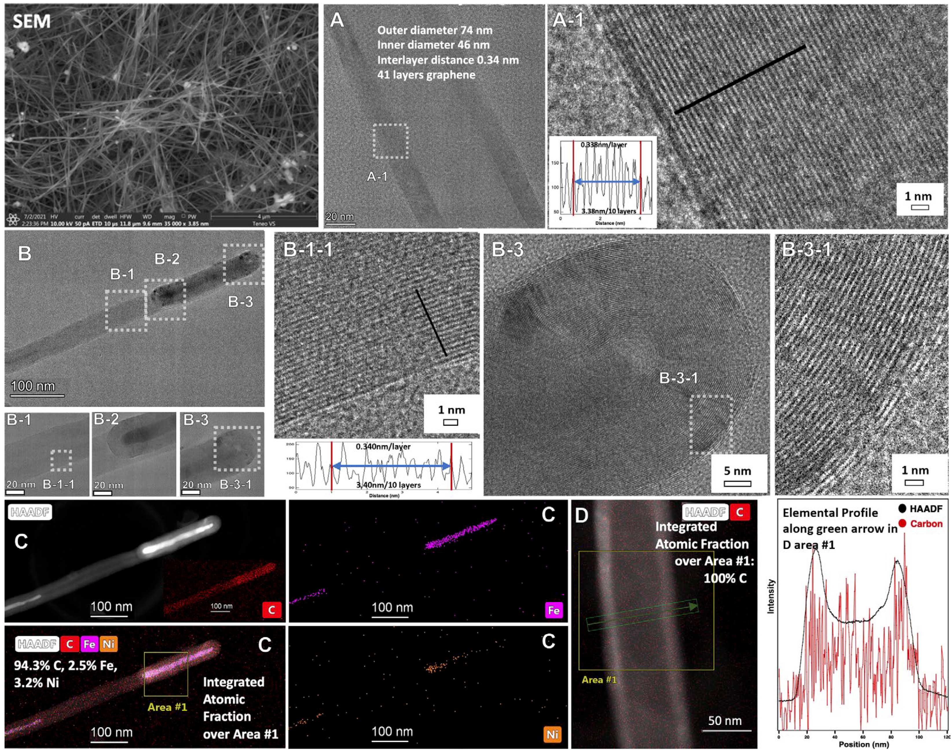
39]. An advantage of forming nanostructures within this macroscopic carbanogel framework is the reduction in respiratory risk associated with nanoparticle handling and shipping. The structure also offers high porosity, as well as electrical and thermal conductivity, making it suitable for integration with composite materials, catalysts, or battery electrodes. Under constant current electrolysis conditions, the product formation on the cathode is continuous, and the growth occurs in the direction towards the anode. The CNT product contains internal transition metal, as shown in SEM, TEM, and HAADF of the conventional C2CNT product shown in
Figure 1. The figure also shows the products’ cylindrical, concentric single-layer thick carbon walls of the CNT with a characteristic separation of 0.34 nm between graphene layers, which gives the product the high strength and electrical conductivity characteristics associated with graphene nano allotropes. As visible in panel B-3-1, at the CNT tip, the graphene walls curve around the transition metal, and as seen in panel D the CNT is pure carbon along its cross section.
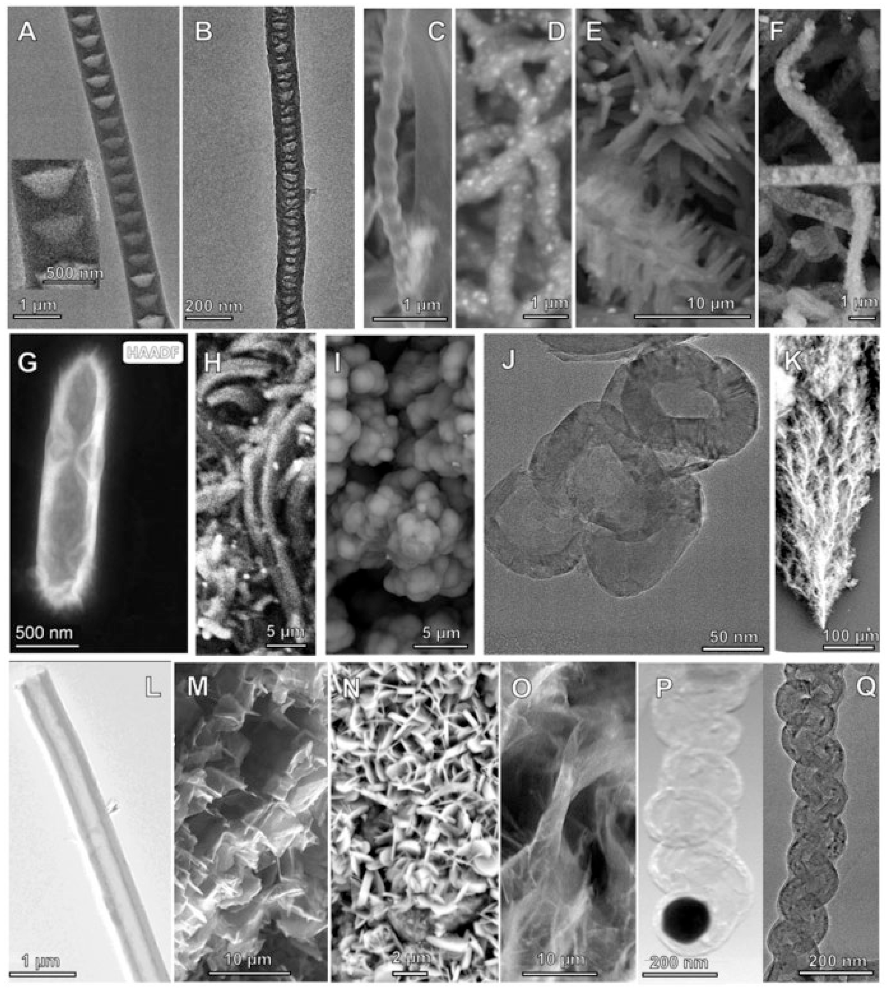
At the small-scale, tuning of the C2CNT electrochemical conditions varies the GNC product, and a number of pure GNC allotropes have been obtained, as exemplified by SEM of various products shown in
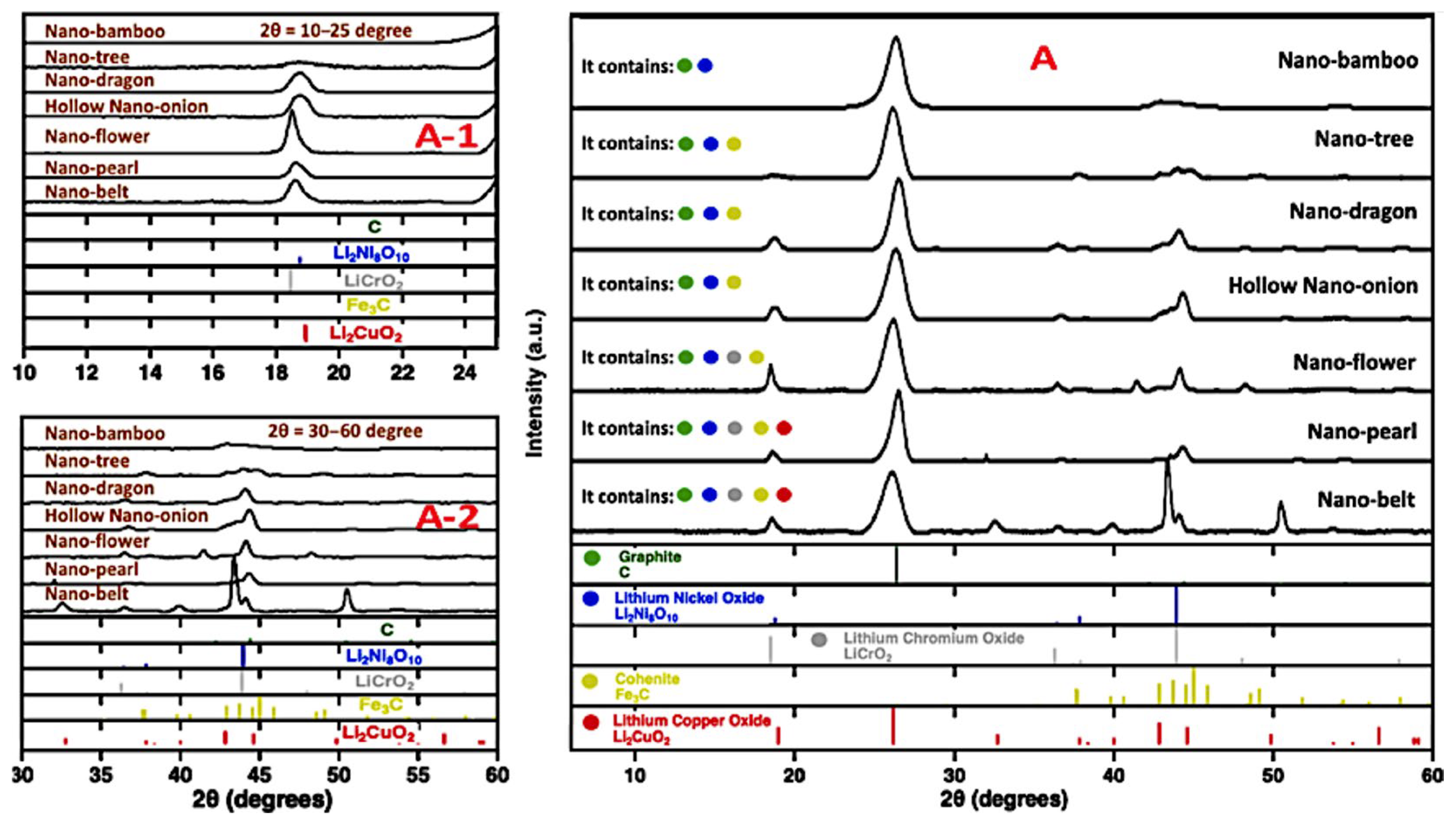
Figure 2, XRD of the product in
Figure 3, and Raman spectra of the products as
Figure S1 of the Supporting Information (SI).
Our previous, fundamental characterization of the C2CNT decarbonization process, includes real-time measurements including generation of the O
2 product, cyclic voltammetry (cv), overpotential, rest potential, coulombic (Faradaic) efficiency, rapid CO
2 solubility in Li
2CO
3 electrolytes. These are summarized in the
SI as Figures S2–S4. The CV (
Figure S2A) discerns between the electrolysis carbon product at 750 °C and the carbon monoxide product at 950°. As shown in
Figure S2B, the rest potential for CO
2 splitting at 750 °C is approximately 1.0 V, which decreases to below 0.9 V with the addition of Li
2O [
30,
40,
41]. The total cell voltage remains below 2 V at a current density of 1 A/cm
2. Similar low electrolysis potentials were observed in molten Sr/Li carbonate mixtures, while other alkali and alkaline earth carbonates exhibit significantly higher voltages [
33,
38,
40,
41]. These trends correlate with the similar calculated thermodynamic affinities of lithium and strontium carbonates for CO
2 binding and release, in contrast to other carbonate systems [
38].
A comparison of the equivalents of charge into the equivalents of product out is an important measure of electrolysis efficiency. For C2CNT,
Figure S3 shows that the Coulombic Efficiency (CE) of carbon production from CO
2 approaches 100% at high current densities. We also observed that CO
2 dissolution into molten Li
2CO
3 containing excess Li
2O is rapid and highly exothermic, enhancing decarbonization as shown in
Figure S4A. This reaction readily regenerates the carbonate consumed during electrolysis.
Figure S4B shows real-time CO
2 gas in and product O
2 gas out measurements in a closed 770 °C electrolysis cell, where CO
2 is split into carbon and O
2, with corresponding changes in headspace gas composition during operation [
35].
To date, the C2CNT process has progressed from bench-scale proof-of-concept to demonstration plants capable of processing tons of CO
2 annually. For instance, implementation at the Alberta Carbon Conversion Technology Centre (ACCTC) and pilot projects funded by Emissions Reduction Alberta and the Carbon XPRIZE have validated the viability of large-format electrolysis cells and downstream GNC handling [
42,
43].
While the core mechanism of molten carbonate electrolysis is well understood, the precise control of carbon morphology remains an area of active investigation. Key hypotheses concern the role of oxide additives in promoting sp
3 defects, the nucleation kinetics of carbide intermediates (e.g., Fe
3C), and the influence of current density on carbon wall curvature and helical assembly [
6,
7,
8,
9,
10,
11,
31,
33,
35]. Molten carbonate electrolysis represents a fundamentally new class of carbon utilization technology with the potential to operate at an industrial scale. Unlike traditional Carbon Capture and Storage (CCS) and Direct Air Capture (DAC) processes, which sequester CO
2 for underground storage, the C2CNT process captures and converts CO
2 into permanent carbon products with monetary value and is a CCUS (Carbon Capture, Utilization and Sequestration) process. This shifts the cost equation from climate liability to economic opportunity.
The purpose of this study is to present new research and recent advancements in the C2CNT process with an emphasis on new large-scale syntheses of diverse GNC allotropes. A recent short communication on large-scale carbon nano-onion synthesis [
44], is expanded and combined with new large-scale syntheses of carbon nano-scaffolds and magnetic CNTs, and developments towards large-scale synthesis of helical CNTs. We aim to present the electrochemical parameters, material outcomes, and scaling strategies that enable production at the kilotons/year level and propose pathways to megaton-scale deployment. Through detailed morphological characterization and process analysis, we demonstrate that the C2CNT process not only delivers high-purity products suitable for advanced materials markets but also offers a credible route for impactful CO
2 removal.
In doing so, this work contributes to the expanding field of carbon valorization and highlights the importance of integrating materials science, electrochemical engineering, and climate policy to address one of the most pressing challenges of our time.
3. Results
3.1. Large-Scale Electrochemical Synthesis of Magnetic Carbon Nanotubes (MCNTs)
The C2CNT process enables the synthesis of a magnetic CNT (MCNT). Due to the high strength and conductivity of CNTs, composites formed with high carbon footprint materials, such as cement, plastics, metals, and papers, and low concentrations of CNTs, are lightweight, stronger, and more conductive. They can be formulated with less material, which can considerably reduce their carbon footprint [
43]. MCNTs set the stage for recovery of CNTs used for catalysis, biomedical imaging, magnet drug delivery, water purification, EMF shielding, CNT recycling, and any end-of-life recovery from CNT composites, such as CNT-cement [
41,
45,
46,
47,
48,
49,
50,
51,
52,
53,
54,
55,
56,
57,
58,
59,
60]. Clearly, MCNTs have a range of useful applications, and an inexpensive, carbon-friendly, large-scale synthesis is needed.
In 2020, we introduced the (small-scale) C2CNT synthesis of MCNTs, and the attraction of these CNTs to a magnet, as well as the C2CNT process illustrating the dissolution of CO
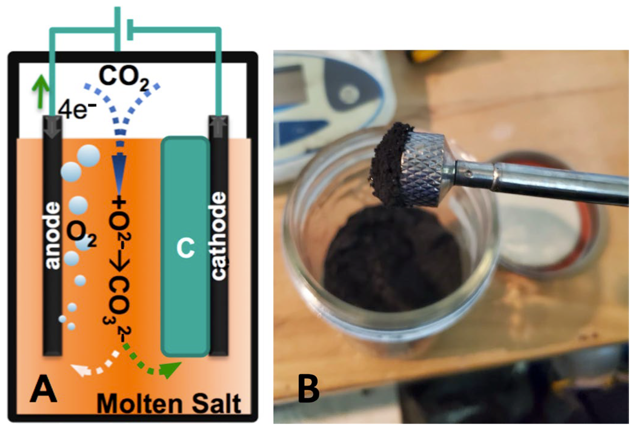
2 by reaction with Equation (2) electrogenerated oxide to carbonate, is shown in
Figure 5. C2CNT MCNTs exhibit ferromagnetic properties due to the encapsulation of transition metals, such as iron or nickel, within the nanotube structure. This encapsulation results from controlled nucleation at the cathode during electrolysis, where metals such as Fe, Ni, or Cr are reduced from the molten electrolyte. The metals are either incorporated as carbides (Fe) or oxides (Ni, Cr), or further reduced to the metal state, embedding them inside the CNTs. HAADF TEM elemental analysis (
Figure 1C) confirms the presence of iron and carbon at the CNT tips. Iron, iron carbide, and nickel are ferromagnetic, with iron being a stronger ferromagnet than nickel. Metal sources include limited anode dissolution during O
2 generation and gradual dissolution of the electrolysis chamber in aged electrolyte. The electrocatalytic O
2 anode is typically nickel or a nickel-based alloy, such as Nichrome, Inconel, or stainless steel. Even pure nickel forms a highly stable oxide layer during molten carbonate O
2 generation [
41], though the released low level of nickel can contribute to CNT nucleation.
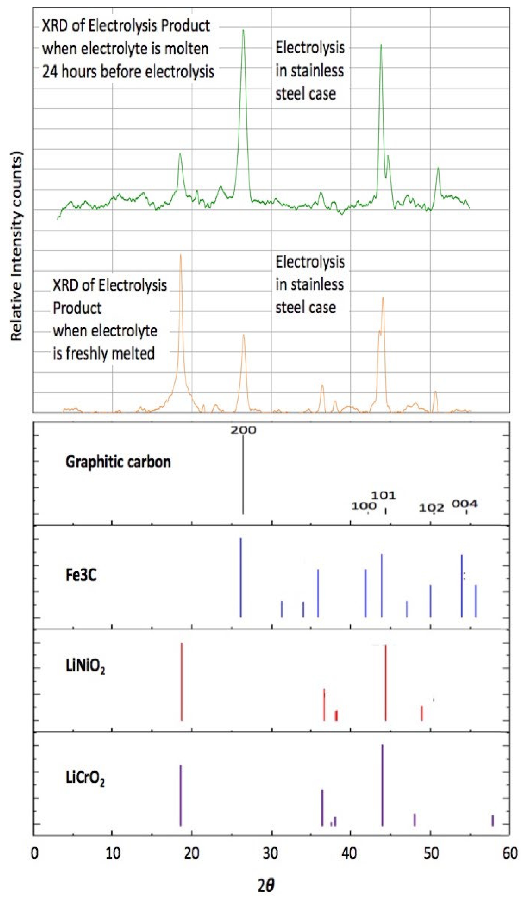
In the case of an iron-free anode, such as Nichrome, post-electrolysis iron can still be sourced from aging stainless steel electrolysis pots.
Figure 6 shows XRD data of CNTs produced using a Nichrome anode in a 304SS pot, with fresh electrolyte or electrolyte aged for 24 h at 770 °C in Li
2CO
3 with a low-level addition of Li
2O. The figure indicates that the CNTs contain primarily Ni and Cr salts from fresh electrolyte electrolysis, and iron carbide from aged electrolyte. Depending on electrolysis conditions, Electron Dispersive Spectroscopy (EDS) reveals the presence of Ni, Fe, or a combination of Fe, Ni, and Cr in the CNTs [
8,
31]. In particular, the presence of excess iron during the electrolysis was shown to create iron carbide, as identified by TEM exhibiting iron carbide’s distinctive interspatial layer separation of 0.2 nm within the graphene structures, and linking electrolysis conditions to carbide formation kinetics in MCNT structures [
8].
The first large-scale (1725 cm
2 area electrodes) syntheses, as exemplified in
Figure S5 of the SI, used a nickel superalloy (Inconel 718 alloy) anode, chosen for its durability and is known for its high-strength, durability, corrosion resistance, and is composed of 50–55% Ni, ~19% Cr, ~19% Fe, ~5% Nb, and smaller concentrations of other elements.
Figure S5A presents an illustration of CO
2 capture in molten carbonate, and its electrolytic release of O
2 at the anode and deposition of carbon (as GNC) at the cathode.
Figure S5B presents the Inconel 718 anode after its 12th electrolysis, and
Figure S5C presents the Muntz Brass cathode after its 4th use for electrolysis, and the surface of both appears.
Figure S5D presents the carbonogel after electrolysis.
Composites often require only a low CNT concentration to generate discernible improvements to a materials’ strength, conductivity, catalytic activity, or EMF shielding capabilities. For example, large strength increases were optimized in CNT-cement composites containing 0.05% CNTs [
45]. A large-scale electrolysis was sought to produce a CNT product with an enhanced magnetic attraction, which could move CNTs for recovery bound at low-level concentrations in composites. This was achieved by replacement of the Inconel 718 anode, with an SS304 anode, which contains ~3.7 times higher iron than Inconel 718 (SS304 composition 66–75% Fe, ~19% Cr, ~9%Ni, and smaller concentrations of other elements). Additionally, SS304 is two orders of magnitude less expensive than Inconel 718.
Remarkably, despite the sustained evolution of hot O
2 at temperatures in excess of 700 °C at the anode, SS304 appears to be as stable as Inconel 718. O
2 gas, which is produced at the anode, naturally rises close to the anode and flows out of the electrolysis chamber. During the electrolysis, the carbon product is under cathodic basis at the cathode providing reductive protection to oxygen released at the anode.
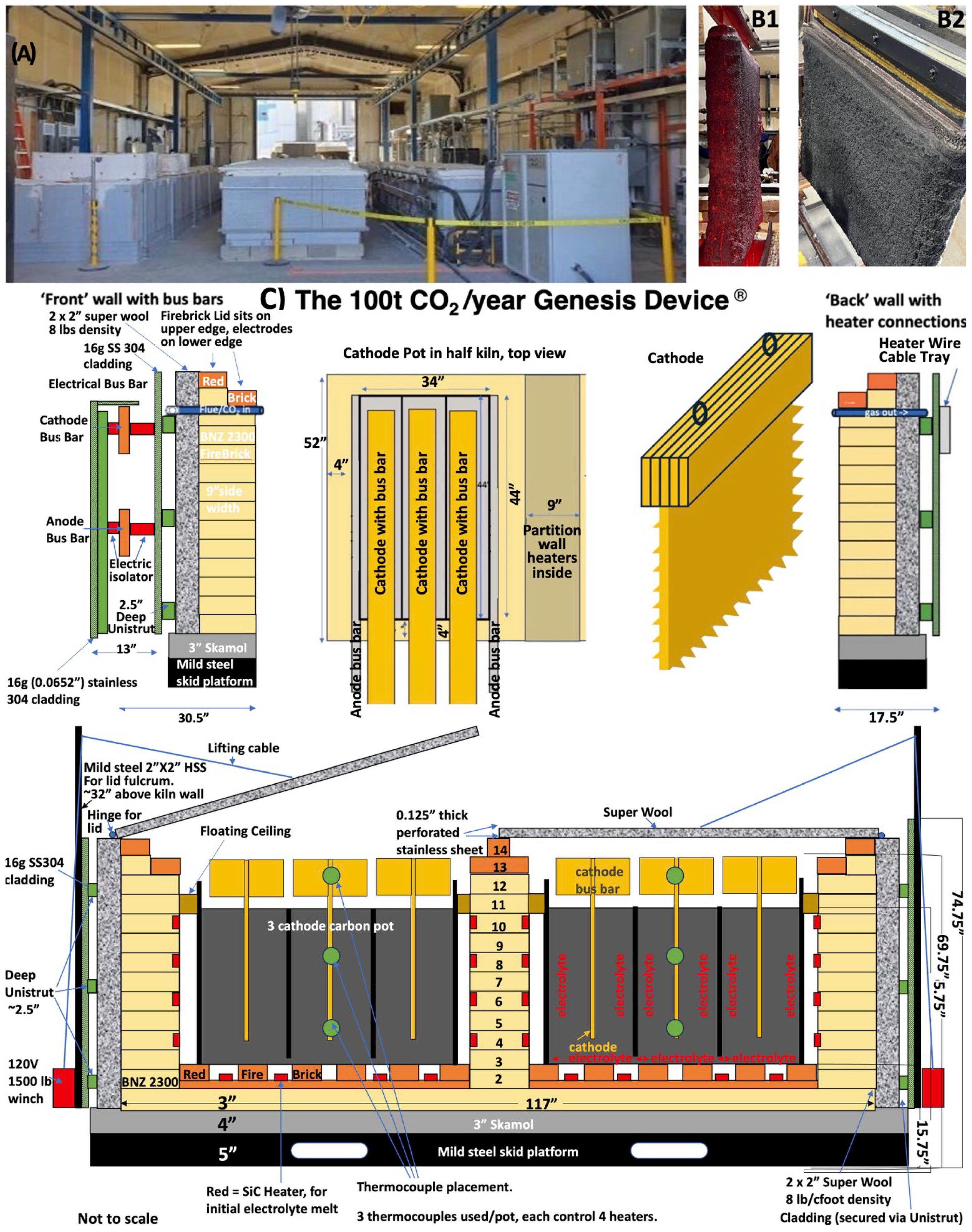
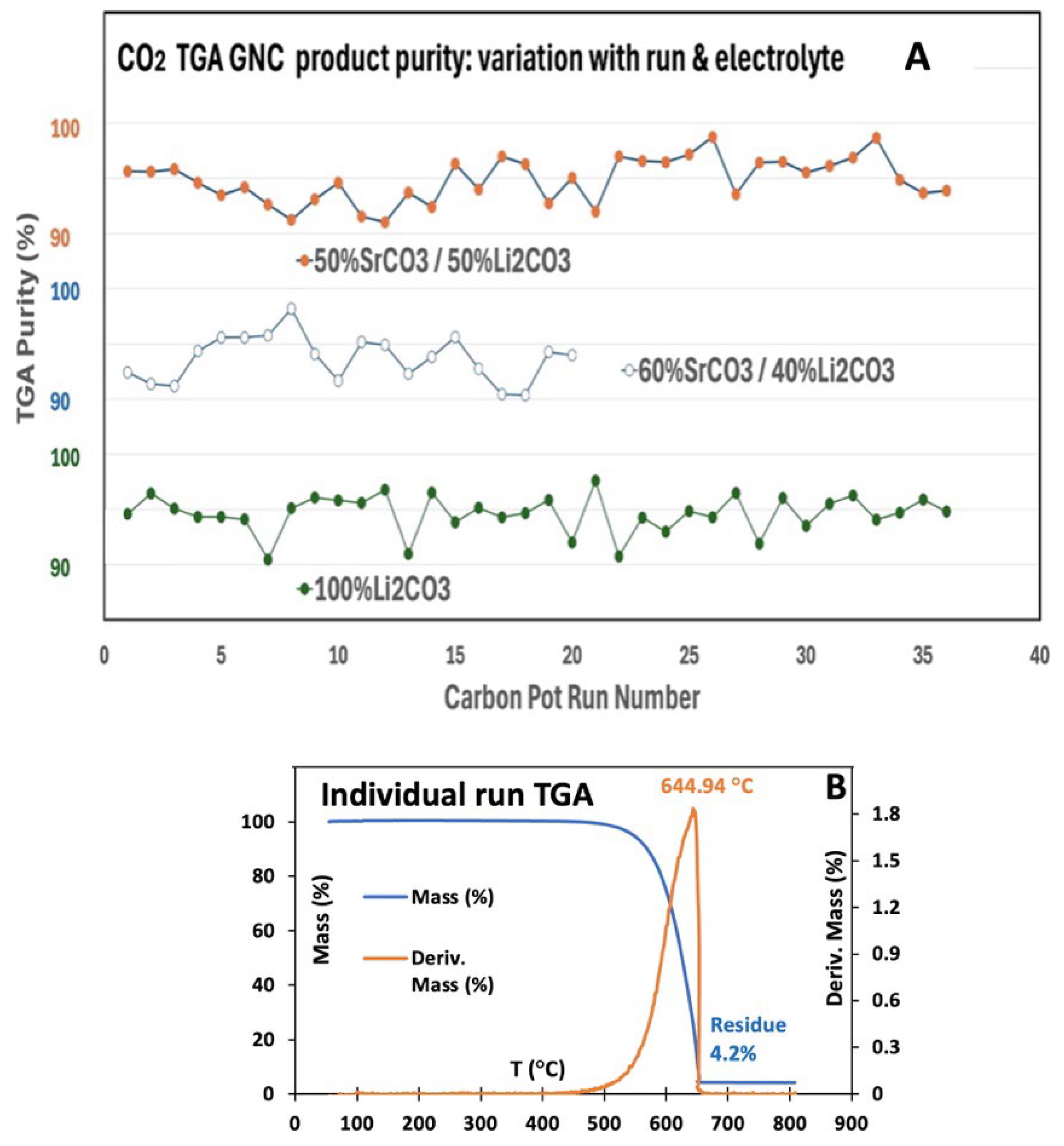
Figure 7A presents the TGA purity of the CNT product produced at large-scales with a SS304 anode and a Muntz Brass cathode in
Figure 4 100 t/y Genesis Device
® C2CNT electrolysis module. Product purity from multiple CO
2 electrolysis runs in lithium or mixed strontium/lithium carbonate electrolytes is shown. TGA-derived product purity from multiple CO
2 electrolysis runs in lithium or mixed strontium/lithium carbonate electrolytes. Purity was calculated as the initial 100% mass minus the residual mass after combustion at 800 °C. The measured TGA purity ranges from 91 to 98%. The SS304 anode (and Muntz Brass Cathode) was stable over the course of all runs in all electrolytes, and the anode retained its activity, color (gray/black), and uniformity throughout. Purity was calculated as the initial 100% mass minus the residual mass after combustion at 800 °C. The measured TGA purity ranges from 91 to 98%. A typical TGA of an individual product is shown in
Figure 7B, including the derivative of the mass change with temperature, with a peak at T
infl. A high peak temperature, such as 644 °C, is typical of a high graphene content, and a highly graphitized structure providing oxidation stability, which is higher than the typical 300 °C combustion of amorphous carbon. TGA consistently shows product purities above 95 percent. Note that the actual product purity is higher than determined in
Figure 7, as the residual TGA mass includes the oxygen amassed during combustion. The durability of SS304 and Muntz brass electrodes in prolonged high-temperature operation is promising. A key to the durability over months of use is avoidance of large temperature swings of the electrolyte. High temperature, approaching within 50 °C of the Muntz Brass melting point of ~900 °C, has caused softening, and warping of the cathode, while freezing of the electrolyte can induce anode passivation.
The enhanced magnetic response of large-scale CNTs synthesized with (high iron) SS304 anodes is seen for a CNT-cement composite containing only 0.05% CNT in Movie 1. The movie is click accessible and is at
https://youtube.com/shorts/JxRyIdGs9bE (accessed on 22 July 2025). The movement of the composite is accomplished with a conventional strength bar magnet (Mastercraft Corrosion Resistant, Nickel-Plated Bar Magnet). The CNTs were synthesized by electrolysis in a 770 °C Li
2CO
3 with a 6232 cm
2 Muntz Brass cathode in an SS304 electrolysis pot, whose walls also served as the anode. The magnetic effect in CNT-composites is observed with CNTs synthesized with SS304 (pot) anodes in a wide variety of strontium/lithium carbonate electrolytes over a wide range of conditions.
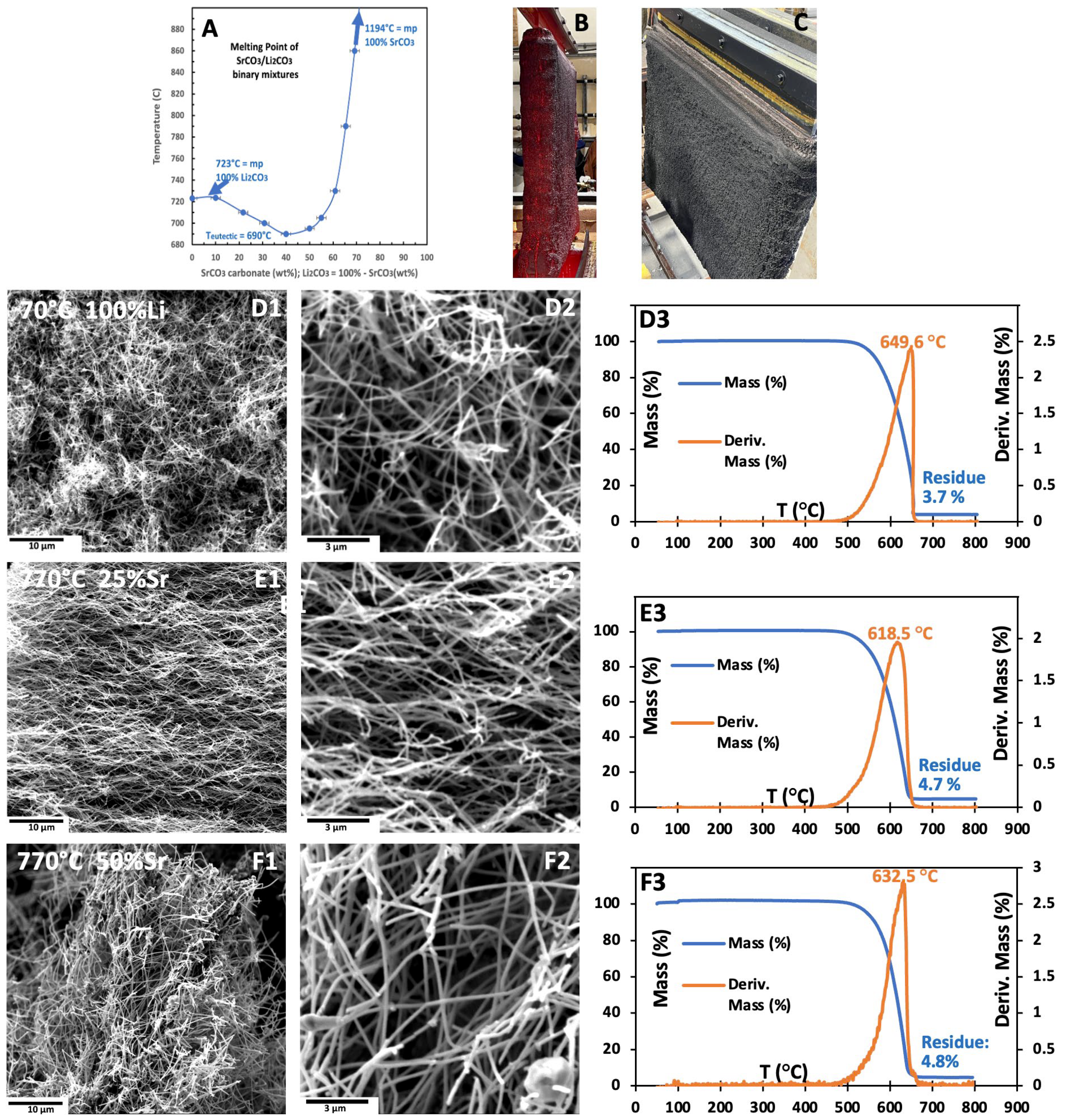
Figure 8A illustrates the unexpected solubility behavior and the reduction in melting point of SrCO
3 (melting point 1494 °C) in molten Li
2CO
3. The melting point of Li
2CO
3 decreases from 723 °C for the pure compound to 690 °C at the eutectic composition of 40 wt% SrCO
3. As the SrCO
3 content increases to 65 wt%, the melting point rises to 800 °C for the binary mixtures. However, temperatures above 800 °C become less suitable for electrolysis due to the increasing formation of carbon monoxide (CO) as a by-product, which becomes dominant by 950 °C [
30].
The mixed (Sr/Li
2)CO
3 electrolytes are particularly advantageous for CO
2 reduction to CNTs and are of industrial significance, given the lower cost of SrCO
3 compared to Li
2CO
3 [
38].
Figure 8B and Figure 10C present an over 1 m
2 active area (11,000 cm
2) Muntz Brass cathode (>1 m
2) coated post-electrolysis with carbanogel. The high electrical conductivity of graphene nanoallotropes enables continuous growth during CO
2 electrolysis as electrolyte/GNC matrix on the cathode. A portion of this electrolyte is loosely retained; for instance, over 30% can be lost by gravitational drip when the cathode is removed from the melt. In molten Li
2CO
3 without additives (e.g., Fe
2O
3), the dripping electrolyte remains clear and chemically unchanged. The remaining electrolyte is more tightly bound within the carbanogel structure. The carbon content of the carbanogel varies by nanostructure type, ranging from 8 to 20% for carbon nano-onions to 2–5% for carbon nanotubes, with the remainder being electrolyte. Recovered electrolyte is reused in subsequent electrolysis cycles. After electrolysis, the carbanogel undergoes hot-pressing to eliminate over 98% of excess electrolyte from the carbanogel, followed by washing of the GNC [
39]. The variation in electrolyte extraction efficiency with press time, pressure and filter type is shown in
Figure S6 of the SI.
SEM and TGA images shown in
Figure 8D–F reveal that electrolyses carried out at 770 °C with 0/100, 25/75, or 50/50 wt% (Sr/Li
2)CO
3 results in the production of high-purity CNTs; the products are MCNTs 10–30 µm long and 70–120 nm in diameter. We have previously demonstrated significantly thinner CNTs with either oxide or borate additions to the carbonate electrolyte [
34]. TGA of the CNTs grown in the three electrolytes are presented in
Figure 8(D3–F3). Exhibiting high oxidation resistance (high T
infl) and low combustion residue.
3.2. Large-Scale Electrochemical Synthesis of Carbon Nano-Onion (CNOs)
The C2CNT process enables electrochemical CNO-formation. CNOs are spherically concentric, layered graphitic nanostructures that represent a distinct and tunable morphology within the broader family of Graphene NanoCarbons (GNCs). A new large-scale synthesis of CNOs is facilitated at moderate electrolysis temperatures, 710–730 °C, using pure or mixed carbonate electrolytes, the process favors CNO growth. These conditions contrast with those needed to produce CNTs, which require higher temperatures.
Originally in a series of small-scale CNO syntheses, specific high-oxide added molten carbonate electrolytes were designed to inhibit CNT formation by suppressing transition metal solubility [
9,
38]. An example is the CNO product shown in
Figure 9, produced by electrolytic CO
2 splitting at 770 °C, 5.9 m (molal) Li
2O in Li
2CO
3 [
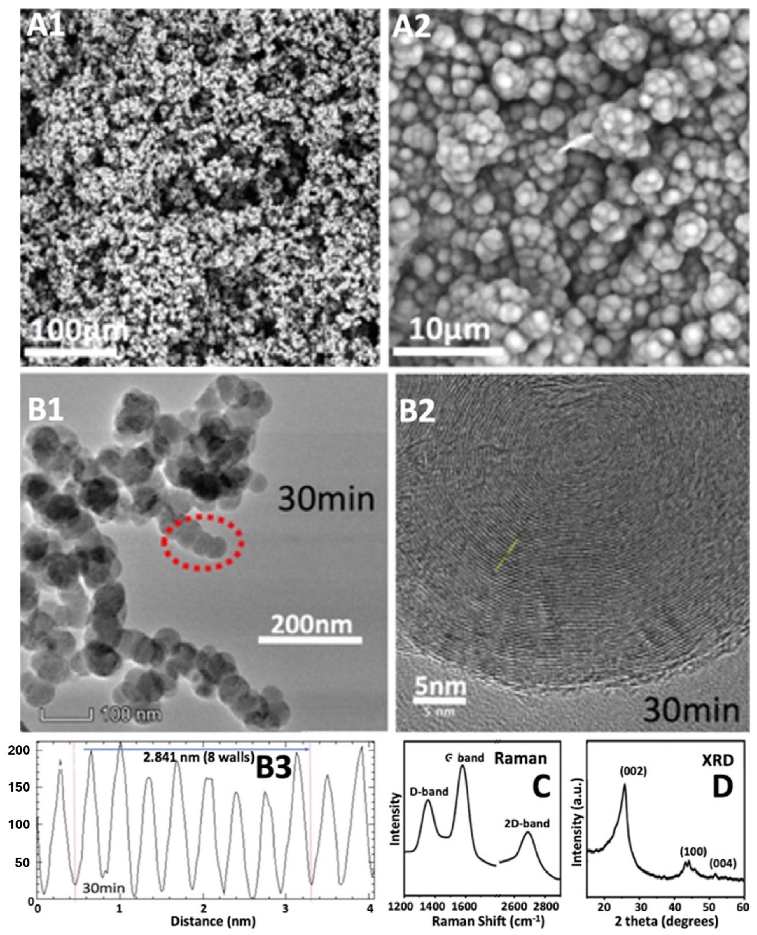
9]. Shown are SEM and TEM of the CNO product as well as Raman spectroscopy (exhibiting a low-defect I
D/I
G peak ratio), and X-ray diffraction (exhibiting the graphitic high-crystallinity 23° XRD peak), which confirm the graphitic nature and uniform shell structure of the resulting CNOs as shown in
Figure 9.
As seen in
Figure 9 the average TEM intensity variation in B3, which is the spacing between concentric graphene spheres TEM B2 is 0.35 nm. This is similar to that measured for other CNOs [
61], although slightly more than the 0.34 nm common for concentric cylindrical separated graphene walls in CNTs, which in turn is nominally larger than the 0.335 nm ideal planar graphene layer in spacing graphite. As a first estimate, it appears the interlayer graphene separation decreases with increasing 0D, 1D, or 2D symmetry. The original study examined small-scale CNO electrosynthesis: after 5 min, ill-defined spheroids form; by 30 min, ~30 nm radius, loosely packed CNOs have formed comprising concentric 0.35 nm spaced graphene shells; at 90 min, the CNOs agglomerate into densely packed CNO clusters [
9].
Here, in a simpler approach to synthesize CNOs at large-scale, the same molten electrolytes used for CNTs in
Figure 8 are utilized, but their electrolysis temperature is decreased to near the melting point to suppress nucleation, inhibit CNT growth, and promote CNT growth. It is proposed that decreasing the electrolyte temperature to near its freezing point may similarly restrict the availability of transition metal cations, thereby facilitating the formation of CNOs. At lower temperatures, the solubility of transition metals declines, and the viscosity of the carbonate electrolyte rises markedly as it approaches the melting point [
62,
63,
64]. These changes are expected to diminish both the reactivity and diffusivity of transition metal species, relative to the dominant carbon-species in the electrolyte. As seen in
Figure 8A, the melting points of 50/50%, 25/75% and 0%/100% Sr/Li
2CO
3 are, respectively, approximately 695 °C, 708 °C and 723 °C.
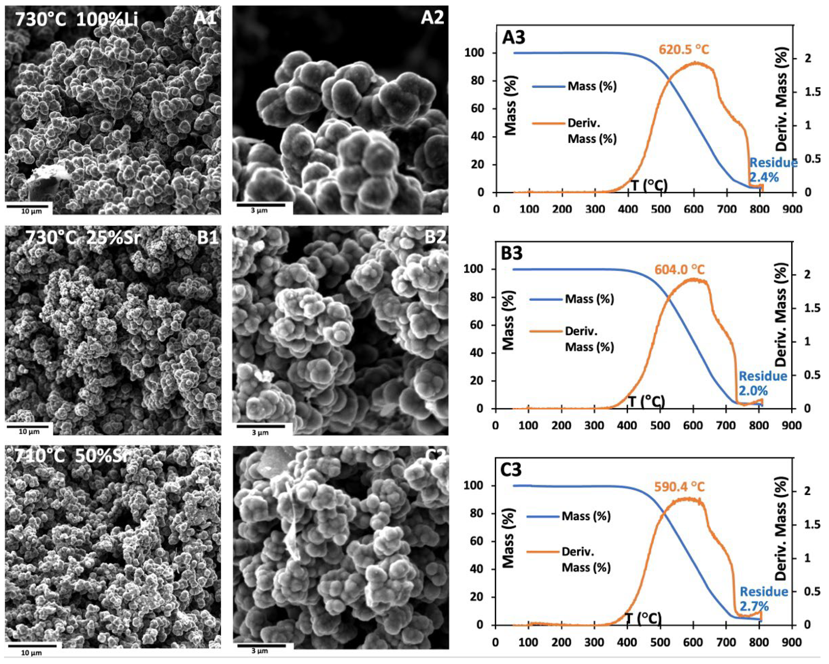
Figure 10 confirms that CNOs are produced in large-scale CNT electrolytes operated under the same conditions, but at lower temperatures near the electrolyte melting point. After lowering the electrolysis temperature from 770 °C to 730 °C, SEM images confirming the CNO morphology after the system was run in 100% Li
2CO
3 (
Figure 10(A1,A2)). Similarly, in 25% SrCO
3/75% Li
2CO
3 at 730 °C (
Figure 10(B1,B2)), and 50% SrCO
3/50% Li
2CO
3 at 710 °C (
Figure 10(B1,B2)) produce high-purity CNO, rather than CNTs. Each of these electrolyses were performed in SS304 pots (anodes) and with Muntz brass cathodes.
A comparison of TGAs
Figure 8(D3,E3,F3), with
Figure 10(A3,B3,C3) reveals that CNOs display distinctive TGA broad shoulder features at elevated temperatures, whereas CNTs present sharp TGA peaks. This observation suggests that CNTs undergo oxidation at a relatively uniform rate, while CNO aggregates likely oxidize via two distinct mechanisms: an intra-particle oxidation rate characteristic of individual CNOs, and an inter-particle rate potentially governed by Solid–Solid Interface (SSI) defects and discontinuities in the graphene layers between closely packed CNOs.
This electrochemical route provides significant operational advantages over traditional methods such as Chemical Vapor Deposition (CVD) and arc-discharge synthesis. It eliminates the use of hydrocarbon feedstocks and transition metal catalysts, instead relying entirely on carbon dioxide from flue gas or the atmosphere. The use of molten carbonate electrolytes also removes the need for complex gas-phase reactor setups and allows for continuous operation. These features reduce both capital and operating costs and contribute to a more sustainable process design.
CNO production has been demonstrated at both small and industrial scales. In the 100 ton-per-year Genesis Device
®, large-area cathodes composed of Muntz Brass are used in combination with durable anodes made of SS304, refer back to
Figure 4 for the standard large-scale configuration. Carbon deposition occurs evenly across cathode surfaces larger than 1 square meter. Like that for the CNT products, the carbon deposits uniformly across the cathode, which can be detached easily, and hot-pressed removing the excess electrolyte, to yield high-purity CNO material.
A high specific surface area is advantageous for a range of nano-carbon applications. As illustrated in
Figure 9 and
Figure 10, carbon nano-onion clusters are ~1–3 µm, while individual CNOs are 20–50 nm, suggesting their potential for significantly enhanced surface area. We observed that the synthesis of loosely packed individual CNOs is achievable through short-duration (<30 min), low-current-density (<0.2 A/cm
2) C2CNT electrolyses [
9]. Characterization of surface area will be essential, and strategies such as deagglomeration of clusters or chemical, thermal, or mechanical treatments aimed at increasing surface roughness and inducing cavitation may further enhance it. A comparative quantification of the surface of CNO and CNS morphologies is awaiting the planned work of separating the 1–3 µm spheroid multi-CNO clusters into 30–50 nm individual CNOs. Distinct inter and intra CNO cluster rates of oxidation that appear consistent with TGA in
Figure 10(A3–C3), suggest that the Solid–Solid Interface (SSI) between individual particles in the CNO cluster may be broken to release CNOs. Breaking apart CNO aggregates into discrete nanoparticles could further increase both overall surface area and the number of accessible surface-active sites. Techniques that have proven effective in disaggregating or purifying carbon nanostructures such as carbon nanotubes (CNTs) include ball milling, thermal and microwave treatments, chemical processes (e.g., acid or KOH treatment), surface functionalization, sonication, exfoliation, and mechanical milling [
65,
66,
67]. Similarly, particle dispersion is a critical factor for many applications. Previous studies have demonstrated effective dispersion of CNOs in aqueous solutions following acid treatment [
68], and in polar organic solvents via alkylation [
65].
CNOs exhibit a wide range of functional properties. Their large surface area, spherical geometry, and graphitic crystallinity support fast electron transport and efficient ion mobility. These characteristics make them well-suited for use in supercapacitor electrodes, tribological coatings, battery additives, and biomedical imaging applications. Their layered structure also supports chemical modification, enabling use as catalytic supports or drug carriers.
3.3. Large-Scale Electrochemical Synthesis of Carbon Nano-Scaffolds (CNSs)
Carbon Nano-Scaffolds (CNSs) are a unique form of graphene nanocarbon produced electrochemically via the C2CNT process. These scaffolds are defined by their open-framework structure, comprising a series of asymmetric, thick, flat multilayered graphene platelets. These platelets are oriented in a 3D neoplasticism-like geometry.
The CNS product was discovered during investigations of GNC formation in low-melting carbonate electrolytes [
10]. A binary 50%/50% Na
2CO
3/Li
2CO
3 eutectic (melting point 500 °C) was modified with a 10 wt% borate, previously shown to improve GNC uniformity [
34]. CNS formation was observed during electrolysis at 670 °C in these high Na
2CO
3 content electrolytes. Sodium ions modify electrolyte viscosity and ionic mobility, suppressing aligned tubular growth and promoting multi-directional carbon deposition. This results in interconnected carbon networks with high porosity, as confirmed by SEM showing branched tubes and porous carbon structures.
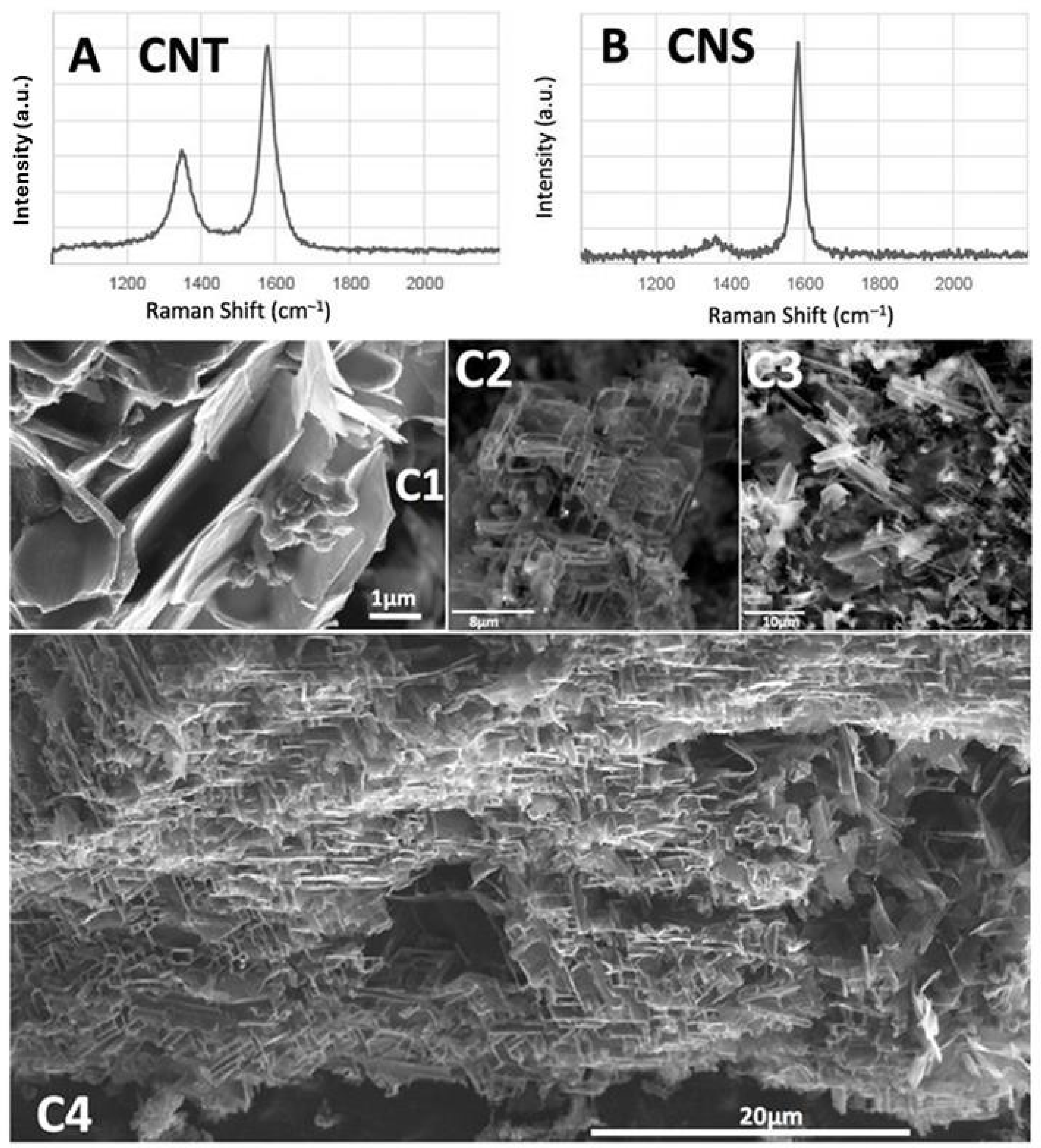
The resulting scaffolded carbon material demonstrates mechanical flexibility, high surface area, and low density. These features make CNSs attractive for diverse applications, including mechanical damping materials, porous catalyst supports, and lightweight conductive composites. CNS samples produced in this manner retain high graphitic purity, with Raman spectra showing intense G bands and low D/G ratios, supporting their structural quality. TGA of the CNS product exhibited a T
inl of ~550 °C [
10].
Figure 11 compares the Raman spectra of the CNT and CNS graphene-based nanostructures, and presents SEM of the CNS product measured in a previous study using small-scale (25 cm
2 electrodes) study, which had introduced these electrolytically synthesized, made from CO
2 in molten carbonate, CNS structures [
10].
Typically, CNT production was conducted at 770 °C with Muntz Brass cathodes and 5% CO
2 flue gas. In a few runs using 10,868 cm
2 cathodes, the electrolysis gas was replaced with 70% CO
2 to simulate more concentrated emissions from sources such as cement or ethanol plants (up to 30% CO
2), in contrast to standard 5% CO
2 from NG power plants. The concentrated gas was prepared by blending regular flue gas with 97% CO
2 gas from an onsite amine concentrator, as shown in
Figure S7 in the SI.
This change disrupted CNT formation. The first run yielded 55% CNT and 45% CNO. The second run from the same electrolyte produced 80% CNO and 20% CNS, as seen in the middle and lower panels of
Figure S7 in the SI. We hypothesize (untested) that the altered CO
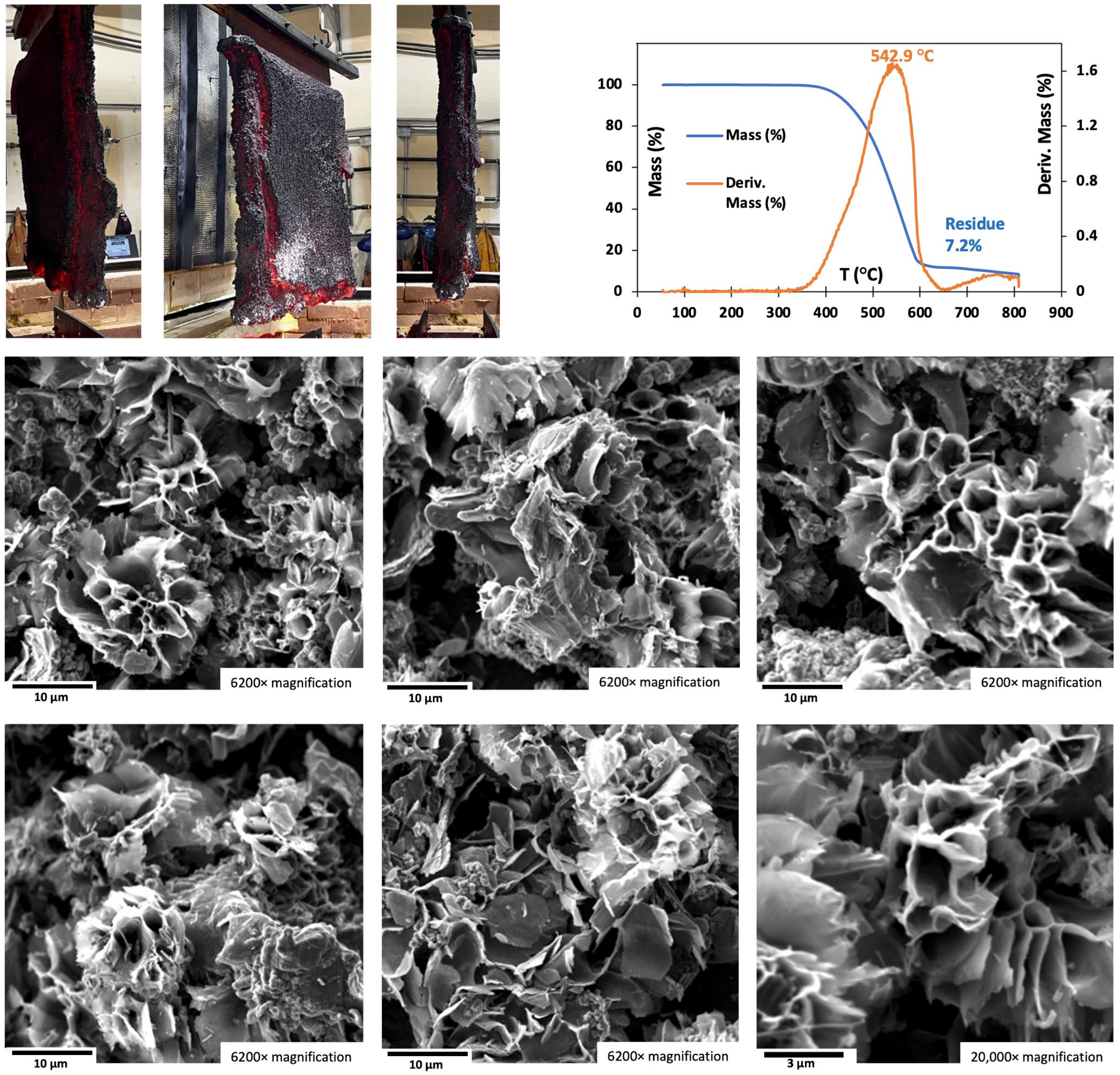
2 feed interfered with the formation of CNT-promoting transition metal nucleation sites. The third run resulted in high-purity CNS (95% CNS, 5% CNO), shown by SEM in
Figure 12. As seen in the Figure, the cathode showed less uniform deposition compared to typical CNT growth. The figure also includes TGA data, indicating high purity and a T
infl of 543 °C. The greater exposed surface area of the CNS compared to CNT’s closed cylindrical structure makes it more susceptible to oxidation. This T
infl is lower than for CNT but consistent with the small-scale study and above the oxidation temperature of amorphous carbon, and is within the expected range for graphene.
It should be noted that the large-scale, pure CNS product shown in
Figure 12 was prepared at high-temperature (770 °C) as a result of a disruption to the regular production runs, and the opportunity to repeat it has not arisen. To reduce cost and improve reproducibility, a proposed optimization involves a ternary or quaternary electrolyte large-scale system with a sodium containing carbonate electrolyte conditions as in the small-scale synthesis,
Figure 11. but comprising SrCO
3, Na
2CO
3, and a small fraction of Li
2CO
3, and with or without an addition of SrB
4O
7. We have previously synthesized this sodium metaborate salt through the reaction of H
3BO
3 and SrCO
3 [
38]. This blend enables operation at 670 °C, a reduced temperature that lowers energy consumption and enhances long-term process stability.
3.4. Scalable Electrolysis Conditions for Helical Carbon Nanotubes (HCNTs)
Helical ‘corkscrew’ CNTs (HCNTs), a highly functional GNC spiral graphene morphology. CVD synthesis of HCNTs can be complex and costly. Initial reports of HCNTs were rare, but this year, simulations of HCNTs and reports of applications of CVD HCNTs have become frequent [
69,
70,
71,
72,
73,
74,
75,
76,
77,
78,
79,
80]. Common applications are to use the ‘spring-like’ HCNT morphology to further the strength, fracture resistance, and durability of composites, as well as their use as sensors. Other potential applications build on the toroidal interaction of HCNTs with electromagnetic fields, such as nano-inductors, piezoelectric devices, and novel electronic metamaterials.
We have previously successfully synthesized, at the small scale, different morphologies of HCNTs, using the C2CNT process under specific electrochemical conditions. Variants of the helical carbon nano structure we have prepared are spiral CNTs resembling fusilli pasta, double-stranded helical CNTs, and flat rather than tube, ‘corkscrew, helical platelets, HCNPs. The ability to produce helical carbon nano-structure directly from CO2 at scale and low-cost positions the C2CNT route as a transformative pathway for greenhouse gas valorization.
Key conditions observed to promote helical carbon nano-structure production by C2CNT electrolysis molten Li2CO3 included. (1) elevated torsional stress, potentially arising from rapid, nucleation-driven carbon reduction processes; (2) the generation of structural defects favoring the incorporation of heptagonal rings instead of the typical hexagonal motifs found in graphene cylinder walls; and (3) the consistent regulation of such defects to induce a recurring spiral morphology. These conditions were facilitated by employing at least two of the following experimental parameters: (i) application of a high electrolysis current density, (ii) inclusion of sp3 defect-promoting additives such as oxides, and (iii) precise control over iron concentration introduced into the electrolyte or deposited on the cathode.
Commercial Al production electrolyses of aluminum oxide to aluminum occur at a high-current density, 0.6 A/cm
2. C2CNT electrolyses were performed at the same current density in a series of small-scale electrolyses (a planar 27cm
2 Muntz Brass vertically separated 1cm from a 27cm
2 Nichrome C planar) in 750 °C Li
2CO
3 with 2 wt% Li
2O electrolyte and various concentrations of Fe
2O
3 also added to the electrolyte. Up to an addition of 0.1 wt% Fe
2O
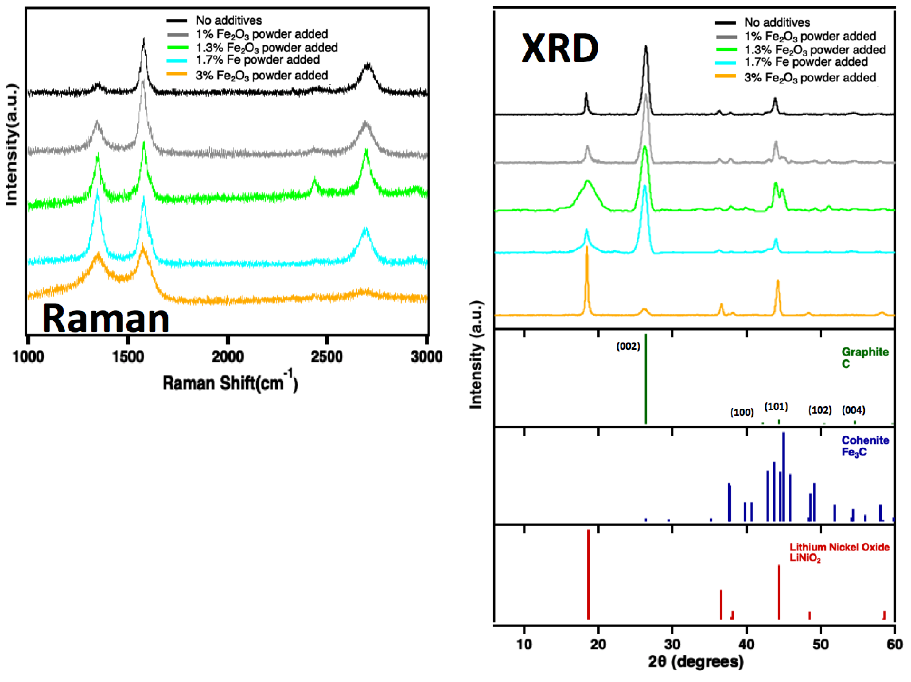
3 to the product was high-purity, conventional CNTs. XRD and Raman of the product using increasing concentration of Fe
2O
3 are shown in
Figure 13. As shown in the Raman spectra on the left side of the figure, increasing the iron oxide concentration leads to a higher degree of disorder, with significant broadening of the Raman peaks at the highest Fe
2O
3 concentration (3 wt%). Similarly, XRD analysis reveals that CNTs formed with ≤1.7 wt% Fe
2O
3 retain a predominantly graphitic structure, along with detectable Fe
3C and LiNiO
2. However, at 3 wt% Fe
2O
3, the intensity of the graphitic peak at 27° is greatly reduced, indicating a shift toward a more amorphous carbon structure at higher Fe
2O
3 concentrations.
With the 1 wt% Fe
2O
3 additive,
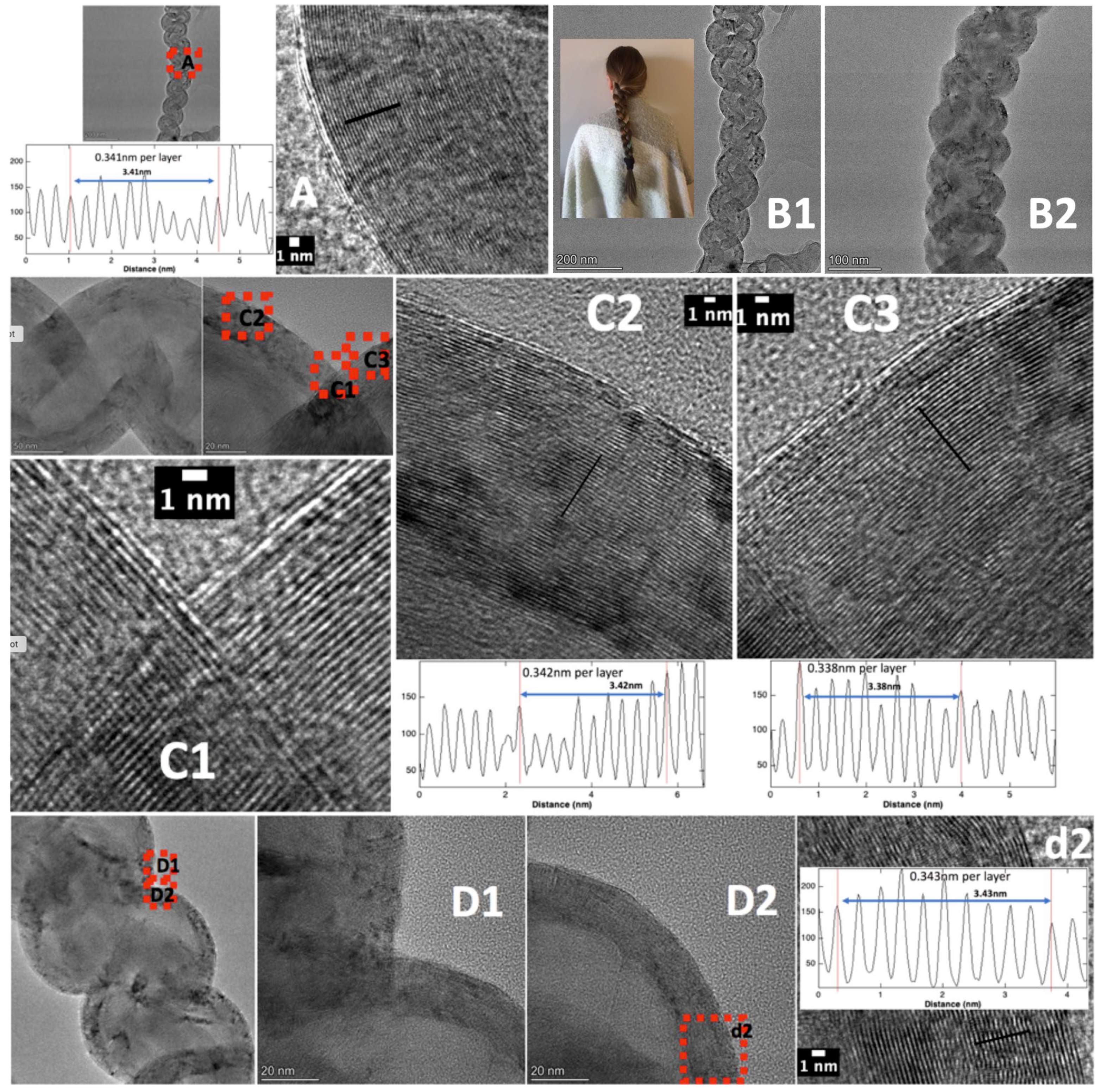
Figure 14 presents the dominant (~85% purity) CO
2 splitting, product double-stranded HCNTs, at low and high TEM magnification from the high current density 2% Li
2O °C Li
2CO
3 electrolysis. The HCNTs have a length of 3 µm and a 0.1 µm diameter. It is seen that 0.34 nm separated graphene multi-walls are maintained throughout the twists and turns of the HCNT structure.
In the range of 1.3–1.5 wt% added Fe
2O
3, helical carbon nanostructures rise to 95% of the observed product, but the product contains ~65% hollow and nearly solid core HCNTs, and ~35% HCNPs. With 1.7 wt% added Fe
2O
3, the HCNP structure increases to 80%, but the presence of a non-helical products, including CNOs, stubby CNTs, graphene-platelets, and amorphous carbon increases. In these small-scale syntheses, the latter non-helical mix of products dominates at concentrations of 3 or 5 wt% [
11], consistent with our previous low current density Li
2CO
3 electrolysis observation that excessive iron concentrations can induce a profusion of carbon nanostructures [
31].
Increasing iron oxide concentrations, respectively, support CNT, then HCNT, then HCNP, then that mix of CNOs, stubby CNTs, graphene-platelets, and amorphous carbons, We propose that iron has a mechanistic role that governs the availability of nanocarbon building blocks during synthesis [
11]. Based on the observations of the small-scale syntheses, when this control is coupled with conditions that promote a high density of defects—favoring the formation of bend enhancing heptagonal, rather than regular graphene planar hexagonal carbon rings, and with a regulated, high current density growth rate that promotes torsional stress, the system enables the preferential formation of helical carbon nanotubes (HCNTs) as the principal product of molten carbonate electrochemical CO
2 reduction.
A systematic variation increasingly multicomponent strontium carbonate electrolytes at high (0.6 A/cm
2) current density, was conducted at small-scale in an attempt to produce larger diameter HCNTs. Rather than HCNTs, instead, 8–15 µm, larger diameter (0.6 µm) carbon nano-pearls, which are linear, CNTs with a repeated bulbous shape as exemplified in
Figure 2C, were produced. SEM of the product is presented
Figure S8 of the SI. The electrolyte consists of 57/20/10/6/5/2 wt% SrCO
3/Li
2CO
3/Na
2CO
3/B
2O
3/SrCl
2/SrO, and as seen by SEM, generates thick carbon nano-pearls, albeit at a lower purity (55%).
A two-step process optimization to develop a large-scale HCNT synthesis has been started. The first component, electrolysis at high current density, has been completed. In addition to the >1 m
2 electrode, J = 0.6A cm
2 electrolyses in various strontium and lithium electrolytes shown in
Figure 8 and
Figure 10 which produce high purity CNT or CNO products, similar high purity products from CO
2 have also been generated at J = 0.7, J = 09 and J = 1.1 A/cm
2 electrolyses in 50/50 wt% Sr/Li
2CO
3. Interestingly, while the 70–100 nm CNT diameter of the higher J electrolyses remains the same, the CNT length tends to increase with current density. The higher current density CNTs are 30–60 µm long and are discernible with lower SEM magnification as shown in the carbanogel particles in
Figure S9 of the SI.
The final step in the large-scale HCNT synthesis optimization (to be completed) will be the addition of oxides to the electrolyte, including Fe2O3. However, unlike the small-scale synthesis, strontium oxide, rather than lithium oxide, will be added. As with the carbonate, SrO is an order of magnitude less expensive than the comparable lithium salt. As an alternative, the in situ electrochemical synthesis of SrO is being explored by stopping the addition of CO2 during the initial phase of the C2CNT electrolysis to suppress Equation (1) allowing electrolytic oxide levels to increase.
3.5. Scaling of GNC Products Produced via the C2CNT Process
The scalability of the C2CNT process has been a central-focus in translating lab-scale discoveries into viable industrial decarbonization strategies. Initial demonstrations of GNC synthesis were performed using cm2-scale electrodes, yielding gram-level quantities of carbon nanostructures. These benchtop tests were critical in identifying the electrochemical conditions needed to tailor product morphology, including variations in temperature, current density, and electrolyte composition. However, to address both market demand and climate relevance, these conditions were subsequently validated and expanded to multi-kilogram and ultimately ton-scale operations.
Scaling efforts aided in the deployment of modular electrolysis systems within a high-temperature kiln configuration termed the Genesis Device®. Each module within this system is designed to convert 100 tons of CO2 per year, producing approximately 25 tons of high-purity GNCs annually. Modules operate continuously under constant current conditions, with individual cathodes measuring up to 1 m2 and electrolyte chambers fabricated from stainless steel 304. The Genesis Device® houses multiple carbon pots, each containing multiple vertically mounted Muntz Brass cathodes and SS304 chamber walls that also function as the anode. As noted in the prior sections, carbon deposits uniformly on the cathode as a solid carbanogel, which can be easily removed, post-processed, and purified.
Importantly, scale-up is facilitated by new synthesis pathways and does not compromise product quality. Across a range of GNC morphologies, including Magnetic CNTs (MCNTs), CNOs, Carbon Nano-Scaffolds (CNSs), and Helical CNTs (HCNT), TGA measurements consistently show purities exceeding 95%, with combustion onset temperatures above 600 °C. SEM and TEM analysis of large-batch samples confirm that the nanoscale features observed at the benchtop are preserved at the industrial scale. For example, uniform shell spacing in CNOs, internal metal encapsulation in MCNTs, and the open framework structure of CNSs have all been retained across kilogram-scale batches.
A modular design philosophy has facilitated replication and scaling. By operating multiple kilns in parallel, a path to megaton-per-year CO2 utilization is technically feasible. Importantly, the infrastructure is compatible with intermittent renewable energy, and electrolysis can be paused and resumed without degradation of the electrolyte or electrodes, offering flexibility for grid integration.
The magnetic CNTs have been produced at scales exceeding 100 kg/year. CNOs have also reached production volumes of approximately 100 kg/year, while CNSs, though more challenging to control, have been produced in smaller but meaningful quantities. The scale-up of HCNTs is ongoing, as well as optimization of yield reproducibility for each of these more complex morphologies through tailored electrolyte blends and refined thermal management.
4. Discussion
This study demonstrates the scalability and versatility of the C2CNT molten carbonate electrolysis process for the direct synthesis of diverse high-purity Graphene NanoCarbon (GNC) morphologies from carbon dioxide. By systematically adjusting electrochemical parameters such as electrolyte composition, current density, and nucleation additives, the process was shown to yield a variety of nanocarbon allotropes, including CNT (including Magnetic and Helical CNTs (MCNTs and HCNTs), carbon nano-onions (CNOs), and carbon nano-scaffolds (CNSs). These morphologies were successfully synthesized at scales ranging from laboratory to new synthesis procedures explored for large-format electrolysis systems capable of converting over a kiloton of CO2 per year. Unlike the large-scale multiple runs of MCNTs and CNOs, CNS and HCNT structures have only been reproduced across multiple runs at small-scale, but large-scale syntheses of each are still under optimization.
The energy requirement for CNT or CNO production Via electrochemical methods ranges from 2.0 MWh/t C, when using heat recovery, oxygen looping, and low-voltage carbonate electrolytes, to 4.3 MWh/t C for high current density electrolysis [
30,
43]. In contrast, carbon nanoparticles produced by chemical vapor deposition (CVD) typically require one to two orders of magnitude more energy [
24,
25,
26,
27,
28,
29,
81,
82,
83,
84,
85,
86,
87].
The chemical environment of conventional CVD differs fundamentally from that of the C2CNT process. CVD is a gas–solid chemical process using organic precursors, while C2CNT is an electrochemical process using CO
2 at a liquid–solid interface. C2CNT achieves lower energy demand due to a higher local concentration of reactive carbon species [
8]. The molten carbonate electrolyte supplies approximately 1 g/cm
3 of tetravalent carbonate species at the electrode surface, enabling efficient reduction. In contrast, CVD relies on several orders of magnitude lower gas-phase density of reactive sites and vapor-phase precursors.
Compared to previous studies that validated the C2CNT concept at the benchtop scale, the current findings represent a significant advancement by confirming consistent material quality and morphology at industrially relevant throughput levels. This progress positions the C2CNT process as a commercially viable carbon utilization platform, offering both climate mitigation benefits and high-value material outputs.
The results are consistent with earlier hypotheses concerning the role of transition metal nucleation and electrolyte tuning in directing carbon morphology. For instance, the formation of ferromagnetic CNTs was facilitated by iron-based nucleation under moderate current densities, which promoted the encapsulation of iron nanoparticles within the CNT structure. This behavior aligns with prior work that identified the importance of transition metal solubility and redox dynamics in the molten carbonate environment.
Transition metals (Fe, Ni, Cr) are integral to the nucleation process. Higher metal content could pose challenges for electronic or biomedical applications. Mitigation strategies include avoidance of high iron concentration through the use of low-iron alloy anodes and or carbon pots, the use of plasma cleaning [
23,
88], and post-product metal purification strategies already used in CVD CO
2 production, such as the breaking of CNT caps followed by washing of the CNT interiors [
64,
89,
90,
91,
92,
93,
94,
95,
96].
A wide range of pure metals, alloys, sheets, screens, and wires have been tested as anodes and cathodes in the C2CNT process [
6,
7,
31,
34]. Electrode material and morphology significantly influence GNC (graphene nanocarbon) formation [
6,
7]. Stainless steel 304, replacing Inconel [
35], is used for the anode and carbon pot due to its durability, corrosion resistance, low cost, and minimal metal contamination. Muntz Brass is preferred for the cathode for ease of product removal, consistent growth, and cost-effectiveness.
Various carbonate electrolytes have been studied for optimal decarbonization. Molten Li
2CO
3 offers the best performance due to high conductivity (6 S/cm) low electrolysis potential, and high GNC purity, outperforming Na
2CO
3 (3 S/cm), K
2CO
3 (2 S/cm), and mixed carbonates [
30,
34,
36]. However, Li
2CO
3 is expensive (
$10K–
$80K/ton) and limited in supply [
97] Alternatives like Na, K, Ca, and Ba carbonates are cheaper (
$50–
$400/ton) but generally less effective and sometimes corrosive (e.g., K
2CO
3 to stainless steel) [
38,
98,
99,
100].
We have presented studies using beryllium carbonate, with a low melting point of 54 °C, or barium carbonate (mp 811 °C) with and without lithium carbonate (mp 723 °C) for carbon capture. While useful for lowering operational temperatures, beryllium carbonate is expensive and its oxide is toxic.
Sodium and potassium carbonates have melting points of 851 °C and 891 °C, respectively. Magnesium carbonate decomposes at 350 °C and calcium carbonate at 850 °C. When mixed with lithium carbonate, all of these exhibit higher, less favorable electrolysis potentials compared to pure lithium carbonate-based electrolytes [
33,
38].
Among non-lithium electrolytes, barium/calcium carbonate mixtures—with borate additives—have shown promise [
36], though they yield higher electrolysis potentials and lower GNC purity than lithium carbonate systems [
36,
38]. Nevertheless, non-lithium carbonates can be useful for producing specific GNC morphologies, such as CNS and CNO, particularly when sodium carbonate is included.
Mixed salts often melt at lower temperatures than their pure components. Notably, strontium carbonate (mp 1494 °C) forms highly soluble mixtures with lithium carbonate, lowering the melting point, down to ~690 °C at 40 wt% SrCO
3 and ~800 °C at 65 wt% SrCO
3 (
Figure 8A), a surprising ~800 °C reduction.
SrCO
3 is non-toxic (used in fireworks), stable in price (~
$1000/ton) [
101], and about ten times cheaper than Li
2CO
3. It also shares a similar thermodynamic affinity for CO
2 binding and release as Li
2CO
3 [
38], aligning with the low electrolysis potentials observed in Sr/Li carbonate C2CNT systems.
To further improve GNC purity and control morphology, increasingly complex Sr/Li carbonate mixtures—ternary to senary—have been developed with additives such as SrO, Fe
2O
3, B
2O
3, and alkali salts [
38].
The synthesis of CNOs under conditions involving pure Li
2CO
3 or mixed Sr/CO
3 electrolytes and intermediate temperatures supports the thermodynamic model in which concentric graphitic shells are energetically favored over tubular elongation. In contrast to conventional CVD methods that require strict control over hydrocarbon precursors and catalyst dispersion, the electrochemical approach used here simplifies production by relying solely on CO
2 as a carbon source, with minimal process complexity and no fossil-derived inputs. In general, we observe the formation of 0D (CN) and 2D (graphene and nano-platelet) structures are favored in C2CNT environments which inhibit the CNT inducing transition metal nucleation is inhibited, and the 0D concentric sphere morphology is facilitate in high torsional growth conditions including high electrolysis current and defect causing conditions, such as iron and oxides, which can promote the formation of non-planar heptagonal, rather than planar-hexagonal carbon rings. Unlike the other C2CNT syntheses, the formation of graphene is a two-step process including the C2CNT growth of carbon nan-platelets followed by room temperature exfoliation of the platelets to graphene [
37]. Several factors induce the growth of 3D symmetry GNC morphologies, such as CNS, which are still being investigated.
The formation of CNSs in Na2CO3-rich electrolytes further confirms the hypothesis that electrolyte composition strongly influences carbon precipitation dynamics. High Na content alters viscosity and ion mobility, leading to disrupted nanotube alignment and favoring three-dimensional, scaffold-like architectures. However, the sporadic appearance of these morphologies in scaled systems suggests that additional factors such as local temperature gradients and electrode geometry may significantly affect growth behavior. Future studies should include thermal mapping and field modeling to follow these effects.
A particularly novel contribution of this work is the reproducible synthesis of HCNTs. These structures, previously difficult to produce reliably, were obtained through the combined use of high current densities and electrolyte additives. The resulting spiral morphologies are believed to arise from torsional stresses and the presence of non-hexagonal defects such as pentagon and heptagon rings. This interpretation aligns with prior literature that linked defect generation to chirality control in carbon nanostructures. The commercial relevance of HCNTs, especially for applications in nano-inductors, biosensors, and advanced electronics, highlights the importance of developing robust synthesis pathways from sustainable feedstocks.
TGA confirmed that all nanocarbon products exhibited high purity, with carbon content exceeding 95 percent after conservative correction for residual catalyst oxides. These results validate the effectiveness of the C2CNT electrolysis conditions in promoting selective carbon growth with minimal contamination or amorphous byproducts. Purity levels of this magnitude are comparable to or exceed those of commercially available carbon nanomaterials, further strengthening the case for electrochemical CO2 conversion.
From a process engineering perspective, the successful implementation of 1 m2 cathode modules and parallelized cell configurations illustrates the feasibility of modular scale-up. Crucially, the material properties achieved at scale remained consistent with those from smaller systems, indicating that key synthesis conditions such as temperature uniformity and current distribution were effectively maintained during scale-up.
While all GNCs carry the advantageous properties of graphene, variations in morphology influence individual GNC characteristics, which are pertinent to their applications. In future studies, it will be of interest to compare the compressibility of (spring-like) HCNTs, to CNSs (high porosity), to CNTs, to (hard) CNOs while comparing their ductility, abrasiveness, lubrication, and thermal and electrical conductivities. The broader implications of this work extend beyond materials synthesis. The C2CNT process offers a dual benefit: it contributes to greenhouse gas mitigation by removing CO2 from industrial or ambient sources, and it provides a direct route to high-value carbon nanomaterials. Unlike conventional carbon capture and storage technologies that focus solely on sequestration, the C2CNT approach integrates carbon conversion into the circular economy.
The C2CNT industrial-scale process employs modular Genesis Device
® kiln systems, as illustrated in
Figure 4. These modules are designed for series connection, allowing scalable CO
2 capture and conversion capacity. Each module, in its current configuration, captures 100 t of CO
2 annually and produces 25 t of GNC Via molten carbonate electrolysis.
Electrolysis occurs within carbon vessels (carbon pots) containing molten carbonate electrolyte and submerged cathodes. The system supports various carbon pot designs, including single- and multi-cathode configurations. The setup shown in
Figure 4 features two Stainless Steel 304 (SS304) carbon pots, each equipped with three cathodes. Electrolysis takes place simultaneously on both sides of each cathode. The three cathodes within each pot are electrically connected in parallel, functioning as a single large-area cathode submerged in a shared electrolyte bath, with anodes positioned between the cathodes.
Table 1 provides detailed specifications of the 100 tons/year CO
2 module, including both input and graphene nanocarbon output. The modules have also operated at current densities exceeding 6 kA/m
2, reaching up to 11 kA/m
2 (1.1 A/cm
2).
The planned scale-up of the C2CNT system from 100 to 1000 tons of CO
2 capture per year per kiln is a direct extension of the current modular design, as outlined in
Table 1. This scale is comparable to existing industrial aluminum plants, which routinely operate molten electrolyzers of similar capacity (~1000 tons per year per unit) in series to achieve megaton-scale output.
Table 1 compares the specifications of the 100-ton and 1000-ton CO
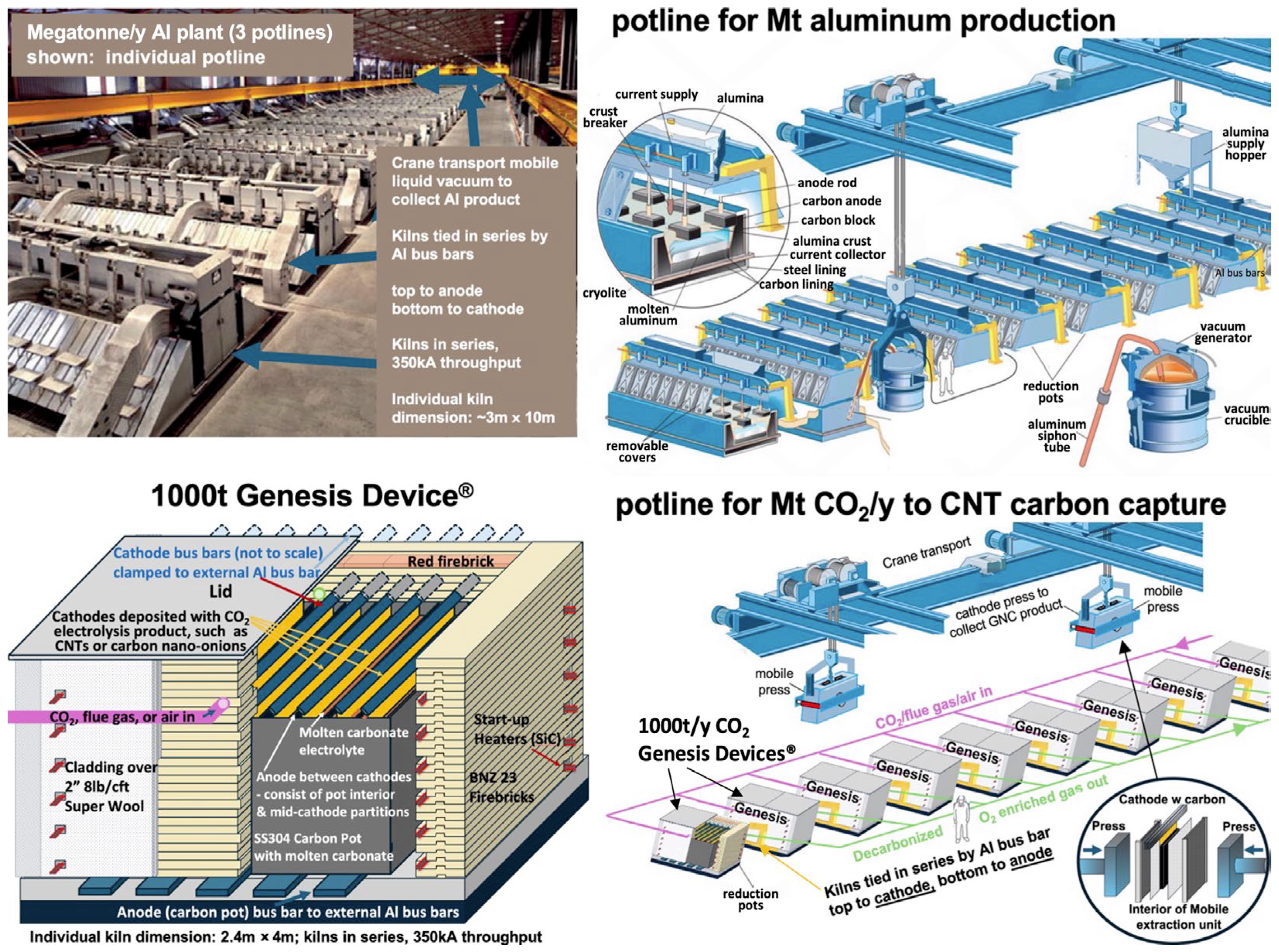
2 capture units. The 1000-ton module, depicted in the lower left of
Figure 15, is designed to operate at a direct current of 350 kA—within the operational range of commercial aluminum smelters. Unlike the smaller unit, which uses multiple carbon pots, the larger kiln employs a single carbon pot containing ten cathodes. Each cathode in the 1000-ton unit has a surface area 3× greater than that of the 100-ton design, and the total number of cathodes increases from six to ten. Operational efficiency has continued to improve, enabling a planned increase in daily operation from 17 to 22 h and an annual operating schedule from 250 to 336 days.
The top left image in
Figure 15 depicts one of three potlines within a modern aluminum production facility, each contributing to an annual output of approximately 1 million tons of aluminum. Each potline operates at around 350 kA direct current, consistent with the typical industrial range of 200–500 kA, and consists of several hundred aluminum electrolysis cells connected in series. Aluminum plants are designed with three potlines integrated into a single structure to achieve this production capacity. As illustrated in the top right corner of
Figure 15, each cell includes consumable upper carbon block anodes made from coke, which are immersed in cryolite electrolyte and are routinely replaced due to their gradual consumption during electrolysis.
The C2CNT process exhibits several operational and structural parallels with aluminum smelting, particularly in its use of molten-phase electrolysis and reliance on non-precious, readily available materials. In aluminum production, alumina is electrolytically reduced to aluminum metal in a cryolite-based molten electrolyte at ~960 °C, using bauxite and sodium hydroxide as feedstocks. In contrast, the C2CNT process electrolyzes CO2 into CNTs within a molten carbonate electrolyte at a lower operating temperature (~770 °C). Key distinctions include the use of an inert oxygen-evolving anode in the C2CNT system, rather than the consumable carbon anode employed in aluminum smelting, which generates additional CO2. Moreover, the C2CNT process uses CO2 as the oxide reactant, a ubiquitous and unrefined input, unlike the processed alumina required in aluminum production.
Both aluminum and GNC electrolytic production processes operate at high current densities, typically in the range of several hundred milliamperes per square centimeter, while maintaining low electrochemical overpotentials. The electrolysis cells in each system are built using readily available industrial materials, including standard metals and ceramic insulators such as firebricks, supported by conventional control and power infrastructure.
Aluminum electrolysis typically operates at around 4 volts and involves the transfer of three electrons per aluminum atom. In contrast, the C2CNT process functions at lower voltages, generally between 0.8 and 2 volts, depending on the current density, and requires four electrons for the reduction in each CO2 molecule.
While the Genesis Device is designed as a modular, bolt-on system, successful commercial deployment requires site-specific integration. Drawing from practices in the aluminum industry, where production is scaled by increasing the number of electrolysis cells, a similar strategy applies to the C2CNT system. Genesis Device
® modules can be connected in series, allowing capacity to scale from initial installations capturing kilotons of CO
2 per year to configurations capable of megaton-scale capture and conversion.
Table 2 outlines the specifications and estimated CO
2 input and graphene nanocarbon (GNC) output for a proposed 1 Mt CO
2 per year decarbonization facility. This plant would produce over 250 tons of GNCs, such as CNTs, with output modulated by adjusting electrolysis parameters. Similarly to large-scale aluminum plants, the 1 Mt CO
2 facility would comprise three lines, each containing several hundred 1000-ton-per-year Genesis Device modules connected in series, as specified in the right-hand column of
Table 1.
Figure 15 provides a side-by-side comparison of a conventional aluminum production facility and the proposed megaton-scale C2CNT decarbonization plant. Development is ongoing for the scale-up of the mobile extraction system used to recover GNCs from the molten electrolyte, as detailed in the
Supplementary Information.
From a process engineering standpoint, the use of 1 m2 cathode modules and parallel cell configurations demonstrates the viability of modular scale-up. Importantly, the material properties of the GNC produced at larger scales were consistent with those obtained from smaller systems. This suggests that critical synthesis parameters, including temperature uniformity and current distribution, were successfully preserved during scale-up.
6. Patents
The discovery of a chemistry of carbon capture and decarbonization by transition metal nucleated molten carbonate electrolysis is broadly covered by US and international patents. Topics of recent patents covered include, but are not limited to:
Discovery of molten carbonate nucleation transition nucleation
Carbon nanotubes and nanofibers from CO2
Magnetic CNTs made from CO2
Carbon nano-onions from CO2
Carbon nano-scaffolds from CO2
Helical CNTs from CO2
Carbon nano-platelets from CO2
Graphene from CO2
Macro-assemblies of CNTs from CO2
Carbon nano-pearl, nano-bamboo, nano-tree, nanorod, and hollow CNO, from CO2
Direct air capture by the C2CNT process
CCUS by the C2CNT process
Discovery, formation and use of carbanogels
Decarbonized molten carbonate decarbonate iron and cement production
Solar and renewable powered molten carbonate decarbonization
The Solar, Thermal Electrochemical Process (STEP)
Extraction and separation of the carbon nanomaterial product,
Amplified carbon reduction by use of C2CNT GNCs made from CO2
Applications of GNCs from CO2 in polymers, cements, metals composites
Applications of GNCs from CO2 in fibers and textiles
Applications of GNCs from CO2 as pure buckypapers
Non-lithium carbonate electrolytes for the C2CNT process
Not listed: International issued, and pending patents due to space limitations.
Issued US patents below are click accessible.
Licht, S. or Licht S. et al., US Patent: 9,758,881, 9,683,297, 9,297,082, 9,080,244, 10,730,751, 10,637,115, 11,028,493, 11,094,980, 11,346,013, 11,402,130, 11,401,212, 11,434,574, 11,512,398, 11,542,609, 11,633,691, 11,643,735, 11,680,325, 11,661,659, 11,724,939, 11,732,368, 11,738,999, 11,746,424, 11,767,260, 11,767,261, 11,821,094, 11,834,749, 11,939,682, 11,905,386, 11,993,855, 12,000,054, 12,006,579, 12,024,782, 12,024,784, 12,031,218, 12,074,872, 12,077,872, 12,077,872, 12,134,685, 12,163,524, 12,267,730, 12,286,717, 12,291,786, 12,305,312, 12,320,016, 12,320,017.
