3.1. Microstructure vs. Mechanical Property
Due to the particularity of the process, the ultra-thin-strip production line is more inclined to produce low-carbon/ultra-low-carbon steel materials. Compared to the traditional hot-rolled products, the carbon content is lower, resulting in a significant reduction in material strength. Due to the characteristics of rapid solidification, the casting structure of the strip and the microstructure of the final product are significantly different from those of traditional products. In the traditional hot-rolling process, the hot-rolled slab of low alloy steel experiences reheating, multiple rough rolling, finishing rolling, and long laminar cooling, and the microstructure is evenly uniform and fine [
24,
25]. The resulting microstructure is basically composed of ferrite, mainly showing irregular polygons. Compared with conventional hot-rolled sheets, the steel produced by the CASTRIP process exhibits coarser prior-austenite grains. This technology directly transforms molten steel into thin strips (1–5 mm thick), followed by a single-pass hot rolling with minimal reduction. The contribution of work hardening to microstructure refinement and strength enhancement in ultra-thin-strip steel is relatively limited. The achieved strength is closely associated with the development of the acicular ferrite and bainitic ferrite. The phase transformation mechanism becomes crucial for optimizing the mechanical properties of ultra-thin-strip steel.
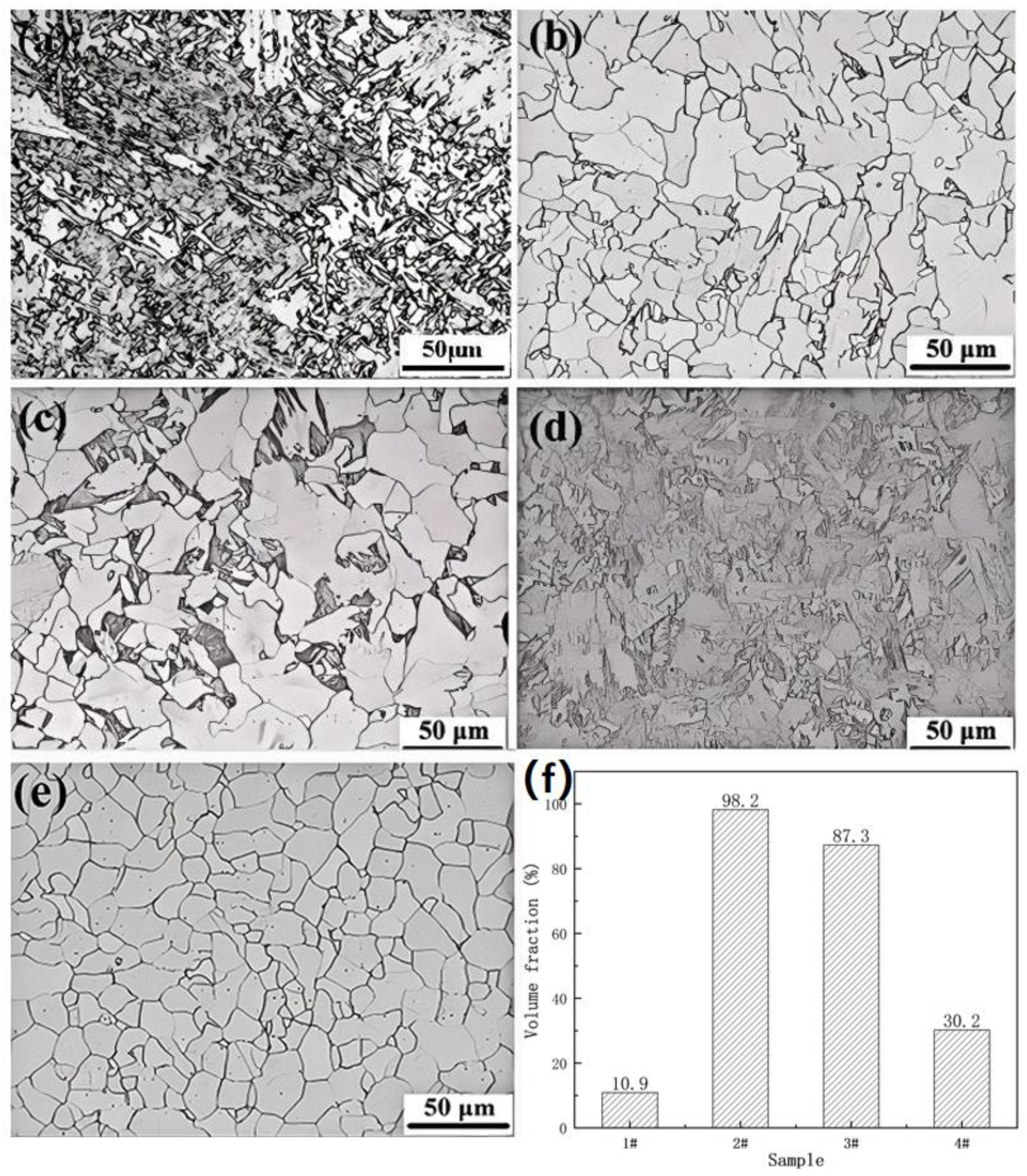
Figure 3 displays the optical microstructures of UCSS steel subjected to normalizing (specimen 2#), water quenching (specimen 3#), and ice-brine quenching (specimen 4#) heat treatments. Varying cooling rates during heat treatment produced diverse microstructures (
Figure 3a–d). The volume fraction of polygonal ferrite in each specimen was quantified using ImagePro1.8.0 software, with results presented in
Figure 3f. For comparison, the microstructure of UCSS steel in its annealed condition, achieved through a heat treatment process where the material was heated to 1050 °C at 5 °C/min, held at this temperature for 6–8 min, and subsequently furnace cooled to room temperature, is shown in
Figure 3e.
In the original UCSS specimen (specimen 1#,
Figure 3a), a significant amount of acicular ferrite and bainitic ferrite was observed, with polygonal ferrite accounting for only approximately 10.9%. After heat treatment, the content of polygonal ferrite increased, though its volume fraction decreased with higher cooling rates (
Figure 3b–d). Annealing resulted in uniform equiaxed ferrite grains with an average size of about 20 μm.
As the cooling rate increased, the proportion of acicular ferrite and bainitic ferrite rose. Specimens 2# and 3# exhibited small amounts of bainitic ferrite and acicular ferrite, while further increasing the cooling rate (specimen 4#) led to a significant increase in their volume fraction. Concurrently, the volume fraction of polygonal ferrite decreased, particularly in specimen 4#, where it dropped to only about 30%.
The UCSS process significantly increases the cooling rate compared to heat treatment, resulting in an extremely fine grain size of the initial austenite solidification structure. The fine original austenite grain boundaries could provide a large number of nucleation sites for bainitic ferrite [
12]. The resulting high phase transformation driving force strongly inhibits the phase transformation that occurs at higher temperatures, especially the formation of polygonal ferrite and pearlite. The formation process of bainitic ferrite and acicular ferrite transformation products was promoted.
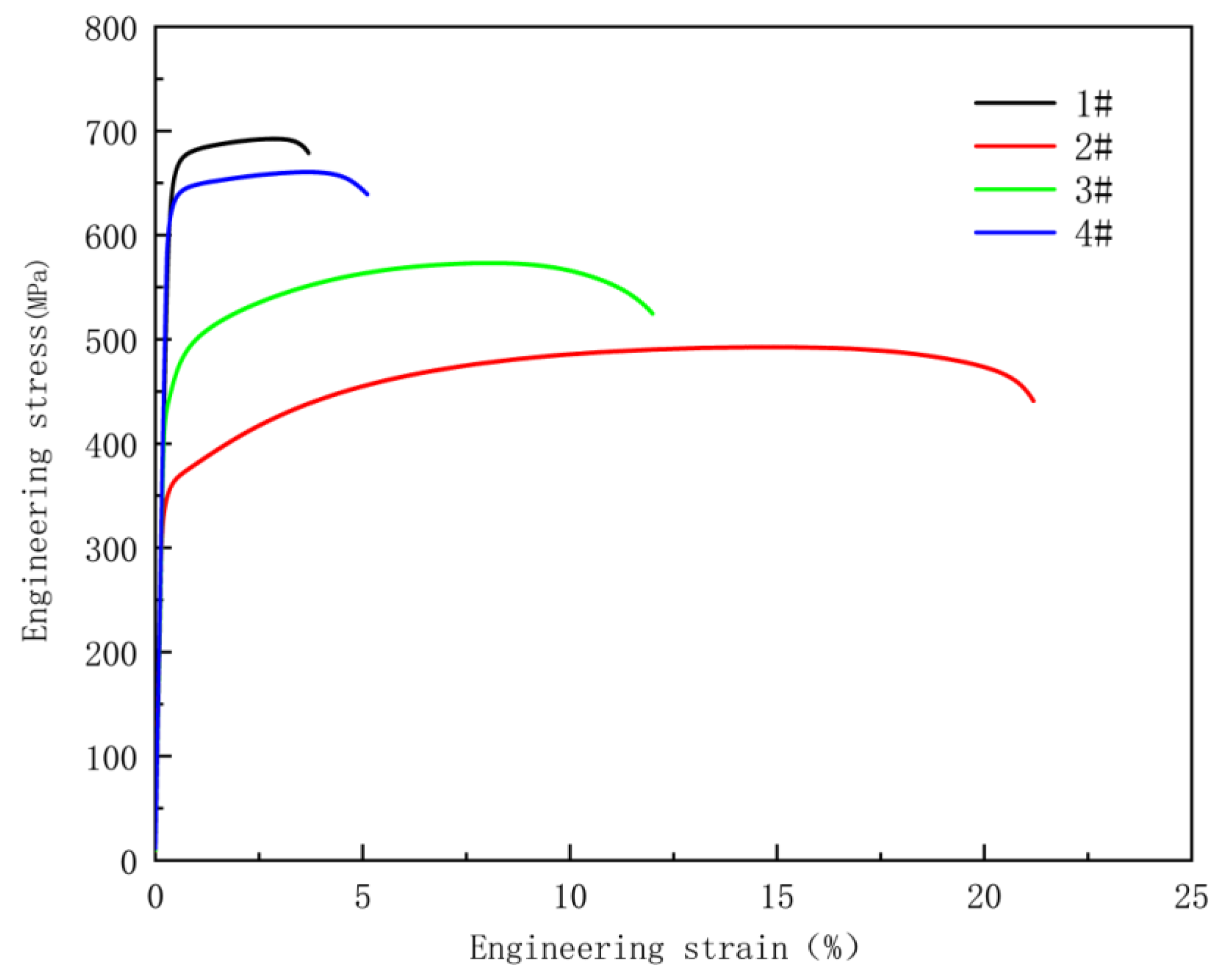
Static tensile tests were conducted on all specimens, with a stretching rate of 2 mm per minute. The engineering stress–strain curves of these four specimens are shown in
Figure 4, and the corresponding mechanical property data are listed in
Table 2. As the cooling rate varies, the coolant achieves an increase in yield strength while elongation decreases, presenting the typical trade-off relationship between strength and ductility. The yield strength of specimen 1# is 665 MPa, which is higher than that of all the heat-treated specimens. This indicates that the cooling rate of the CASTRIP process is much higher than that of conventional laboratory cooling methods. As can be seen from
Figure 3f, the volume fractions of acicular ferrite and bainite in specimens 1# to 4# are 89.1%, 1.8%, 12.7%, and 69.8% respectively, which correspond to the tensile strengths of 692 MPa, 492 MPa, 572 MPa, and 660 MPa. This clearly indicates that acicular ferrite and bainite contribute significantly to the tensile strength.
The transformation temperature of ferrite in general low-carbon steel ranges from 780 to 850 °C, while the transformation temperature range of bainitic ferrite is approximately 450–610 °C [
25,
26]. Acicular ferrite appears under a medium cooling rate (20–40 °C/s), and lamellar bainitic ferrite forms under a high cooling rate (>40 °C/s) [
27]. Due to the presence of additional elements, the transformation temperatures of ferrite and bainite in UCSS steel are expected to be higher than those of general low-carbon steel, but the increase in cooling rate reduces the starting and ending transformation temperatures of undercooled austenite, thereby increasing the phase transformation driving force. As shown in
Figure 3b,e, when the cooling rate was <10 °C/s, equiaxed ferrite (polygonal ferrite) and a small amount of pearlite developed. As shown in
Figure 3c,d, when the cooling rate reached 60 °C/s, acicular ferrite and bainitic ferrite formed at the original austenite grain boundaries. As the cooling rate increases, the plate-like characteristics of bainitic ferrite become more obvious [
25,
26]. Theoretically, in the undistorted austenite, ferrite nucleates preferentially at the grain boundaries and grows inward. In the deformed austenite, the deformation-induced nucleation in the grain interior induces ferrite at the grain boundaries, and inhibits grain boundary bainite [
28]. The UCSS process only has a small amount (about 20%) of deformed austenite, so its effect on grain refinement by nucleation of intragranular products is not significant [
24]. The ultra-fast cooling rates lead to an increase in dislocation density and residual stress. As the volume fraction of ferrite and bainite increases, the elongation of the experimental specimens significantly decreases.
3.2. Transformation Process and Nucleation Mechanism of Supercooled Austenite
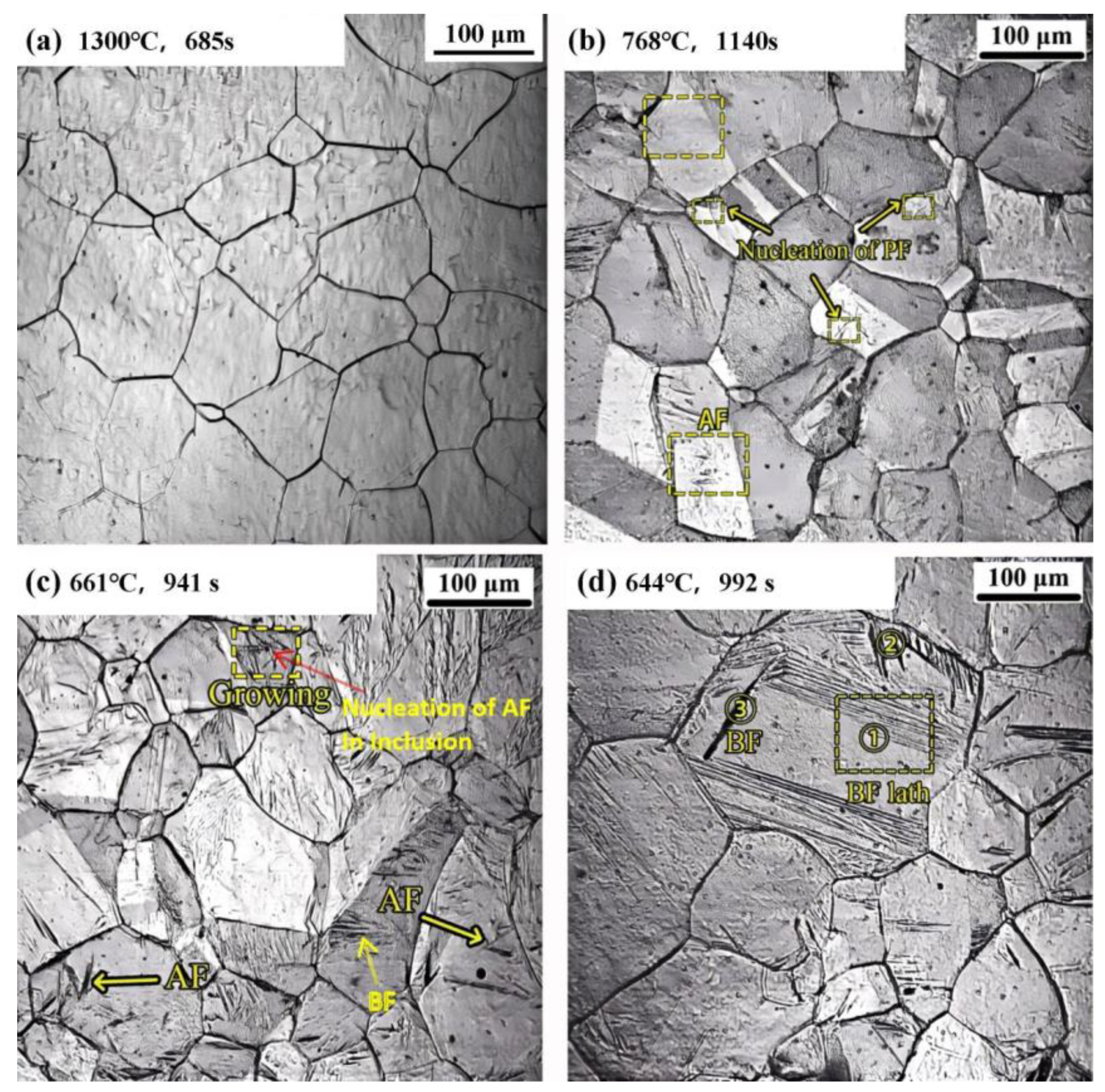
The phase transition of supercooled austenite in UCSS was observed in situ using confocal laser scanning microscopy (LSCM). The process under different cooling rates was recorded. As shown in
Figure 5a, when the specimen was heated to 1300 °C, austenite grains developed. The austenite grain size ranges from approximately 30 to 90 μm, and the grains are of nonuniform size. After being held at 1300 °C for 685 s, due to the complete dissolution of the elements, the austenite grain boundaries are more visible, and no further growth is observed. The austenite remained stable during subsequent slow cooling to approximately 1100 °C. Under these initial conditions, the phase transformation processes of metallographic structures were observed at three different cooling rates: 1 °C/s, 10 °C/s, and 100 °C/s.
At a relatively low cooling rate of 1 °C/s, the resulting structure is predominately composed of equiaxed polygonal ferrite, and the average grain size of the primary austenite is about 60 μm. As depicted in the yellow circle in
Figure 5b, when the specimen was cooled to 768 °C for 1140 s, nucleation of polygonal ferrite at grain boundary occurred. With further cooling, the ferritic block region expands with a relatively smooth boundary, and the rate of interfacial displacement is slow. After nucleation at the grain boundary of the original austenite, the ferrite grows towards one direction, and the polygonal ferrite grows asymmetrically on both sides. According to the literature [
29,
30], polygonal ferrite is a typical structure resulting from a diffusive phase transition. To minimize the nucleation barrier, the nucleation of polygonal ferrite at grain boundaries typically exhibits an N-W or K-S relationship with one side of the austenite, and the interfacial migration in this case is fast [
31]. The other side of the austenite tends to have a random orientation, and the migration rate of this type of interface is slow. As shown in
Figure 5b, a small amount of acicular ferrite nucleation is observed. This may be attributed to the slow cooling rate, which leads to a long nucleation incubation period. The driving force of acicular ferrite transformation exists at some inclusion sites, contributing to the formation of acicular ferrite [
16].
When the cooling rate reaches 10 °C/s (
Figure 5c), the kinetics of transformation from austenite to ferrite is significantly higher. Notably, a portion of the austenite preferentially transforms into acicular ferrite. At this cooling rate, the average grain size of primary austenite is about 80 μm. With the continuous cooling process, the inclusions within the crystal act as nucleation sites. The red arrow in
Figure 5c indicates an inclusion nucleation. Simultaneously, the bainite ferrite with lath bundles begins to grow at the grain boundaries, as can be clearly seen in the yellow marked area of
Figure 5c. After cooling to 661 °C for 941 s, the acicular ferrite in the crystal grew quickly, and the acicular ferrite was interlaced and underwent continuous nucleating. At this stage, the microstructure consists of acicular ferrite, bainite ferrite, and ferrite at the grain boundaries.
The precipitation of inclusions leads to the formation of solute-depleted regions around them. These regions possess a chemical driving force that promotes the transformation of austenite into acicular ferrite, thereby increasing the content of acicular ferrite. It is generally accepted that the consumption of austenite-stabilizing elements in the matrix surrounding non-metallic inclusions can enhance the chemical driving force for acicular ferrite nucleation. Currently, the theories of manganese-depleted zones (MDZs) and carbon-depleted zones are the main research focus [
32,
33,
34,
35]. The formation of solute-depleted zones around inclusions has specific requirements for the inclusions. However, not all inclusions can promote the formation of acicular ferrite. It has been demonstrated that the inclusion engineering of the CASTRIP process facilitates the nucleation of acicular ferrite [
2,
5,
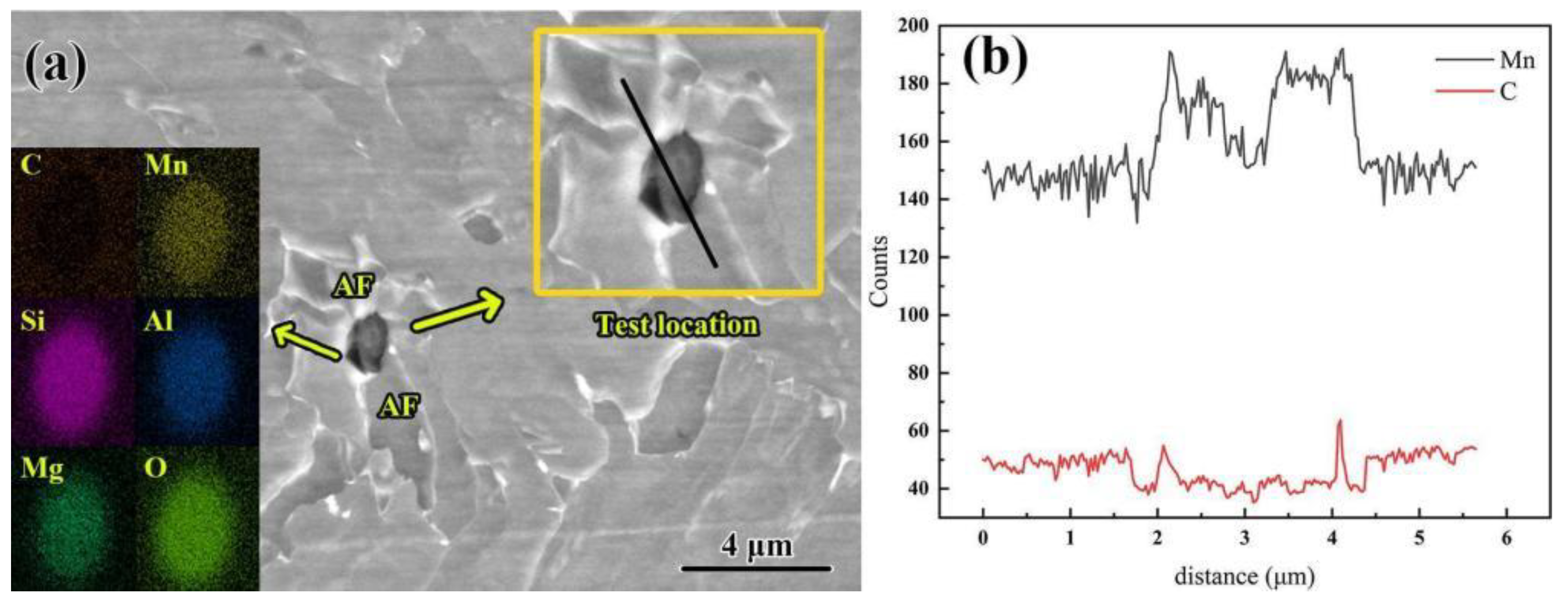
11]. In general, the CASTRIP process results in small and uniformly distributed inclusions in ultra-thin-strip steel. To investigate the impact of the solute element content in the matrix surrounding non-metallic inclusions in UCSS on acicular ferrite nucleation, typical non-metallic inclusion in UCSS was measured along the growth direction of acicular ferrite. As shown in
Figure 6, in the composite inclusions enriched with C, Si, Mn, Al, and Mg elements the manganese element is concentrated within the non-metallic inclusions, and no obvious dilution area was observed, while carbon is present in the matrix surrounding the non-metallic inclusions. The width of the depleted area is approximately 200 nanometers and is distributed within the core of the acicular ferrite.
Since both Mn and C are austenite stabilizers, the depletion zone formed by the consumption of C atoms offers the chemical driving force for the nucleation of acicular ferrite. Based on the solute-poverty theory, the transformation mechanism of acicular ferrite in the carbon-poor region can be described as follows: γ→γ′ + γ″ → AF + γ1. The formation of the austenitic carbon-poor zone can be divided into two distinct stages. Firstly, a carbon-poor zone (γ′) and a carbon-rich zone (γ″) develop. Subsequently, acicular ferrite nucleates and grows within the carbon-poor region of austenite, while some austenite remains gradually transform [
36,
37]. The theoretical validation of the chemical driving force provided by inclusions reveals that upon cooling, intragranular austenite is more inclined to transform into acicular ferrite. However, due to its own insufficient driving force, high cooling rates and large undercooling conditions are required to create the necessary conditions for the formation of a large quantity of acicular ferrite. Non-metallic inclusions act as inert interfacial media that reduce the nucleation barrier by providing low interfacial energy for acicular ferrite nucleation. When the interfacial energy between ferrite and inclusions is lower than that between ferrite and austenite, ferrite preferentially nucleates on the surface of inclusions [
17]. Therefore, non-metallic inclusions create favorable conditions for ferrite nucleation and readily serve as nucleation sites for acicular ferrite.
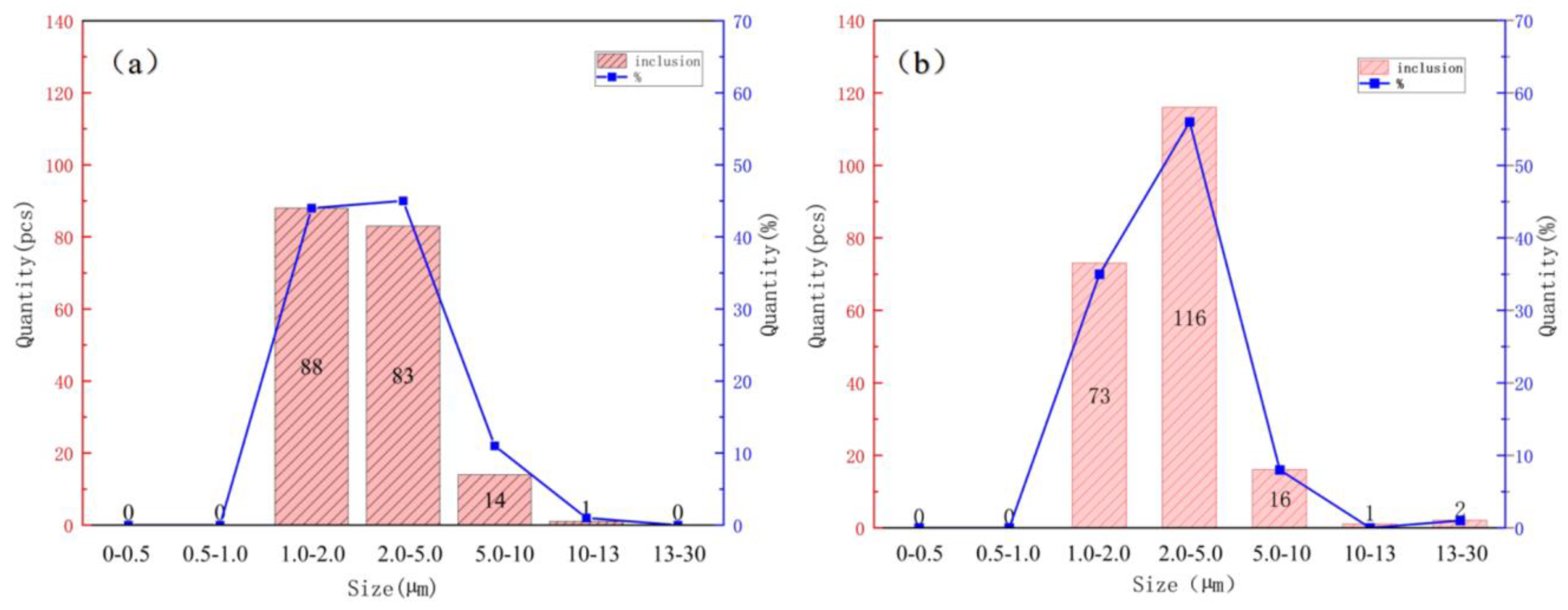
To prevent the occurrence of surface or other harmful defects in thin-strip casting and rolling, ultra-thin-strip casting and rolling impose stricter requirements on the purity of molten steel. As depicted in
Figure 7, the size and quantity of inclusions in the UCCS and air-cooled specimens were statistically analyzed through the OTS software in SEM. It is evident that the size and quantity of inclusions in thin-strip casting and rolling specimens are very small, which is closely related to the inclusion control in the steelmaking process. However, a comparative analysis reveals that the inclusion sizes in the UCCS specimen are mainly concentrated in the range of 1.0–2.0 and 2.0–5.0 μm, while the inclusions in the air-cooled specimen are mainly concentrated in the range of 2.0–5.0 μm. It has been verified that the non-metallic inclusions in ultra-thin-strip steel demonstrate fine and homogeneously dispersed characteristics, which play a crucial role in facilitating acicular ferrite nucleation.
At a cooling rate of 100 °C/s, the austenite grain size ranges from approximately 70 to 120 μm. When the continuous cooling temperature reaches 672~600 °C, bainite transformation occurs in the supercooled austenite. As shown in
Figure 5d, after cooling to 644 °C for 992 s, the primary characteristic of bainite ferrite nucleation and growth at the grain boundary is the growth in regions I and II perpendicular to the original austenite grain boundary into the interior of the grain. At this stage, the growth in bainite ferrite at the original location I vanishes, and the parallel bainite ferrite bundles begin to grow in large quantities. The bainite ferrite at location II shows no measurable change, and it can be inferred that the irregular bainite ferrite at the grain boundary was the first to complete its transformation. Simultaneously, a new bundle of bainite ferrite starts to grow on the bainite ferrite at location III. The previously formed bundle of bainite ferrite has stopped growing, and the two bundles of bainite ferrite grow within the crystal at an angle of 30°, which exhibits characteristics similar to those of acicular ferrite. This type of bainite ferrite nucleated within the grain has a relatively large grain size. Thus, some scholars suggest that this acicular-like ferrite can be essentially regarded as intra-grain bainite ferrite [
17]. However, the bainite ferrite with intercrystallite nucleation typically has a larger size, and its lath density is lower than that of acicular ferrite, which makes it easier to distinguish.
Bainite ferrite preferentially nucleates at austenite grain boundaries because austenite grain boundaries are carbon-poor regions [
38,
39]. The subunits in the bainite ferrite strip are formed in the carbon-poor region. When compared with the transformation in pure iron (γ-Fe→α-Fe), there is no essential difference between these two transitions; both are processes of fcc to bcc transformation. The phase transition that nucleates and grows rapidly at grain boundaries can be considered as a massive phase transition in the middle temperature region. The composition of the new phase is identical to that of the parent phase, and the phase transition does not depend on diffusion. Interfacial movement, that is, atoms jumping across the phase boundary through non-cooperative thermal activation, is the main process of massive phase transition [
27]. Therefore, the nucleation and growth of bainite ferrite can be explained by the non-cooperative thermal activation transition mechanism of interfacial atoms [
37]. During the incubation period of bainitic transformation, carbon-depleted zones inevitably form in supercooled austenite due to local fluctuations of carbon atoms, while grain boundaries simultaneously satisfy the conditions for structural and energy fluctuations, facilitating ferrite nucleation. At this stage, the phase interface between austenite and bainitic ferrite grows through a non-cooperative thermal activation mechanism of atomic migration [
40]. The driving force primarily originates from the free enthalpy difference between austenite and bainitic ferrite [
27]. The specific volume of ferrite in the cube is large, and the matrix is prone to expand in the process of supercooled austenite transformation, resulting in an increase in distortion energy. This promotes the nucleation and growth of new bainitic ferrite on the nearby carbon-poor region.
The body-centered cubic ferrite possesses a relatively large specific volume. During the transformation of supercooled austenite, the matrix tends to undergo volumetric expansion, resulting in increased distortion energy. This strain energy promotes the nucleation and growth in new bainitic ferrite in adjacent carbon-depleted zones. Through this repetitive process, parallel bainitic ferrite laths ultimately form within a single prior-austenite grain boundary.
Between these bainitic ferrite laths, carbon-enriched zones remain in the austenite due to the consumption of carbon-depleted regions. Combined with the multi-directional compressive stress exerted by the bainitic ferrite laths, these carbon-enriched austenite regions become increasingly stable. If cementite precipitation is inhibited, they may persist as carbon-enriched retained austenite or transform into secondary cementite.
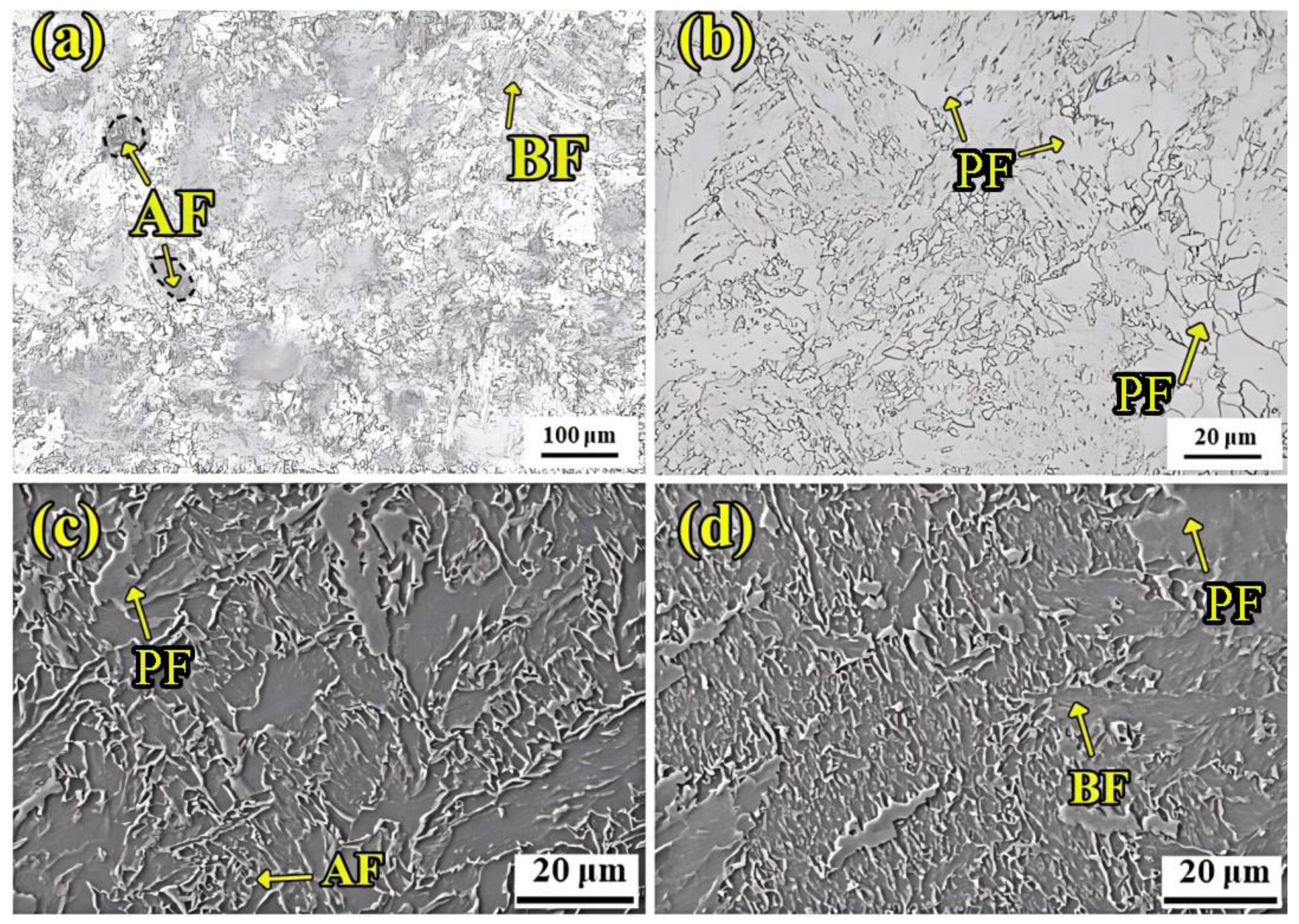
3.3. Microstructure Characteristics of UCSS Steel
Figure 8 shows the microstructure of UCSS steel at room temperature. UCSS steel is mainly composed of polygonal ferrite (PF), bainite ferrite (BF), and acicular ferrite (AF). The most important factor leading to this organizational characteristic is the particularity of the CASTRIP process, which is mainly reflected in the control of solidification fundamentals, rapid cooling control, rolling process control, and chemical composition control (mainly ultra-low carbon) [
1,
5].
The UCSS steel was designed as an ultra-low-carbon steel, resulting in a minimal carbide content.
Figure 8c,d present high-magnification SEM images of the UCSS steel. It can be seen that the content of cementite at the ferritic boundary is extremely low. The parallel arrangement of bainite ferrite is the prominent feature. Due to the low rolling reduction in the CASTRIP, only part of the original coarse austenite grains underwent recrystallization. As a result, polygonal ferrites and coarse quasi-polygonal ferrites precipitated along the grain boundary of the proto-austenite. Acicular ferrite is characterized by an interlocking fine acicular morphology with fine grains, which is not visible at low magnification.
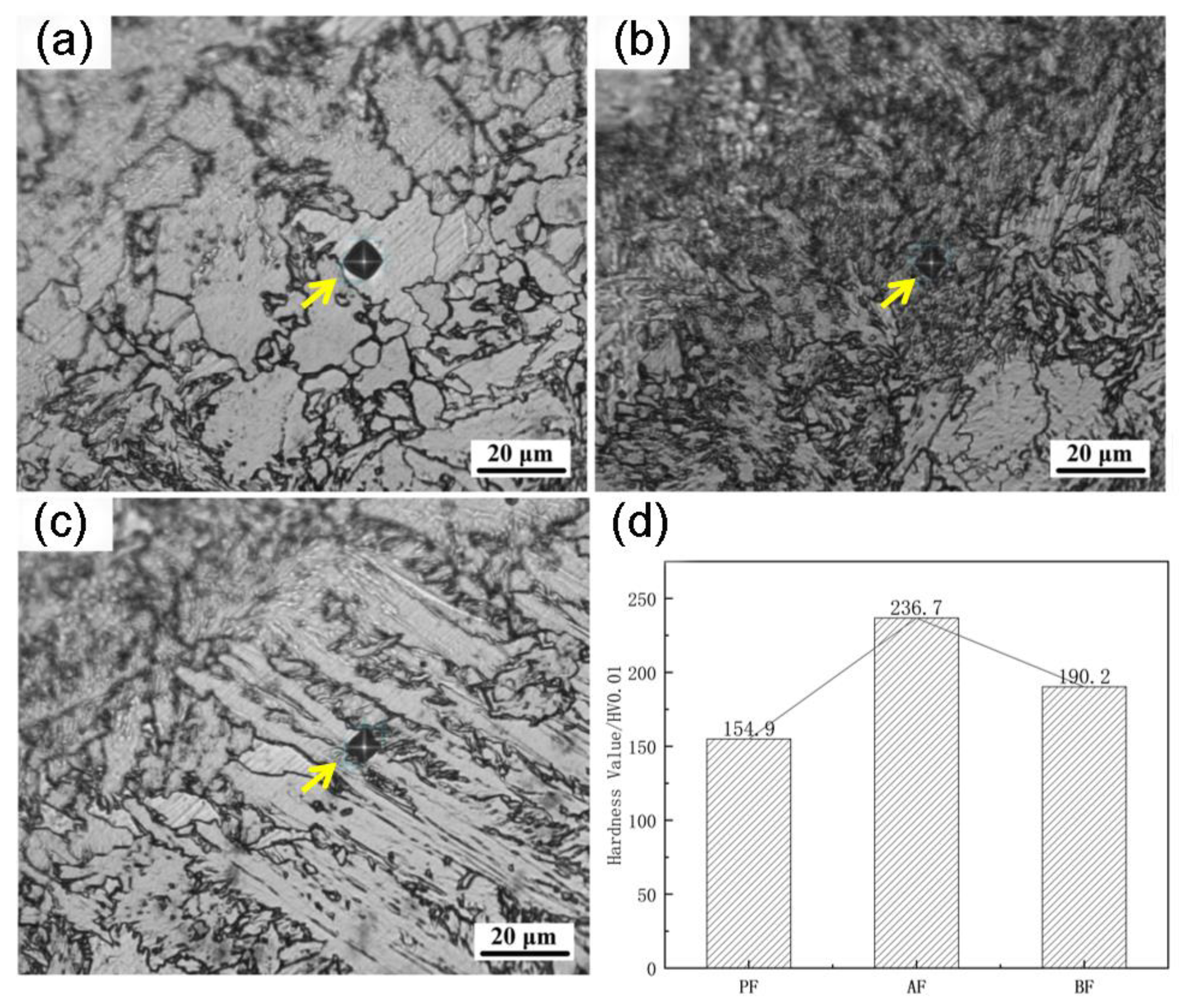
Figure 9d shows the microhardness as measured in polygonal ferrite (
Figure 9a), acicular ferrite (
Figure 9b), and bainite ferrite (
Figure 9c) in UCSS. The acicular ferrite shows a microhardness of about 236.7 HV, which is higher than for the bainite ferrite (190.2 HV) and the polygonal ferrite (154.9 HV). The acicular ferrite and bainite ferrite predominantly possess small-angle grain boundaries, while high-angle grain boundaries typically present in the polygonal ferrite. The prevalence of small-angle grain boundaries in acicular and bainite ferrite contributes to their relatively higher hardness compared to polygonal ferrite. Evidently, acicular ferrite and bainite ferrite play a pivotal role as the primary strengthening mechanism for enhancing the strength of the ultra-thin-strip steel matrix.
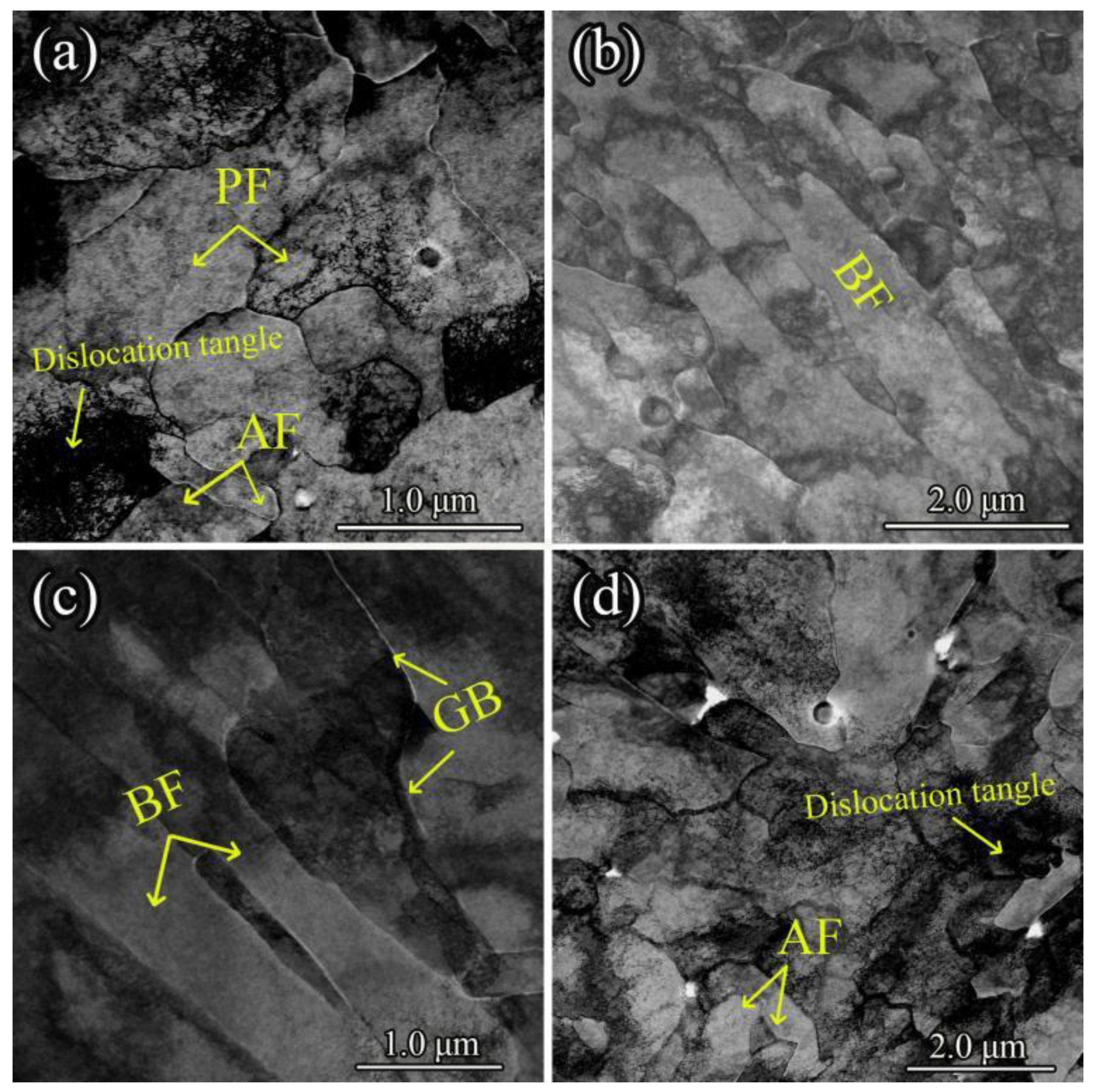
Transmission electron microscopy (TEM) was employed to examine the distribution, morphology, and fine structure of ferrite and bainitic ferrite in UCSS, as depicted in
Figure 10. The room-temperature microstructure primarily consists of polygonal ferrite (PF), bainitic ferrite (BF), and acicular ferrite (AF). Quasi-polygonal ferrite was not observed in TEM due to its excessively large grain size.
Figure 10a illustrates the typical morphology of polygonal ferrite, with a grain size of approximately 2~4 μm. This polygonal ferrite coexists with acicular ferrite, which is characterized by its slender and pointed morphology and intricate interlocking of ferrite units. Furthermore, high-density dislocation substructures are present in the vicinity of the acicular ferrite, leading to dislocation entanglement.
Figure 10b,c show the typical morphology of bainitic ferrite. It predominantly exhibits a lamellar structure arranged in parallel. Since carbide distribution is essentially absent at the bainitic ferrite interfaces, it is termed carbide-free bainite. Additionally, bainitic ferrite grows from the grain boundaries into the grain interiors.
Figure 11 presents the morphology of bainitic ferrite and its corresponding magnified views. The lath width between the bainitic ferrite plates ranges from 0.2 to 0.5 μm. The regions between the bainite laths contain high-density dislocation substructures that aggregate to form dislocation tangles, as shown in
Figure 11b,c.
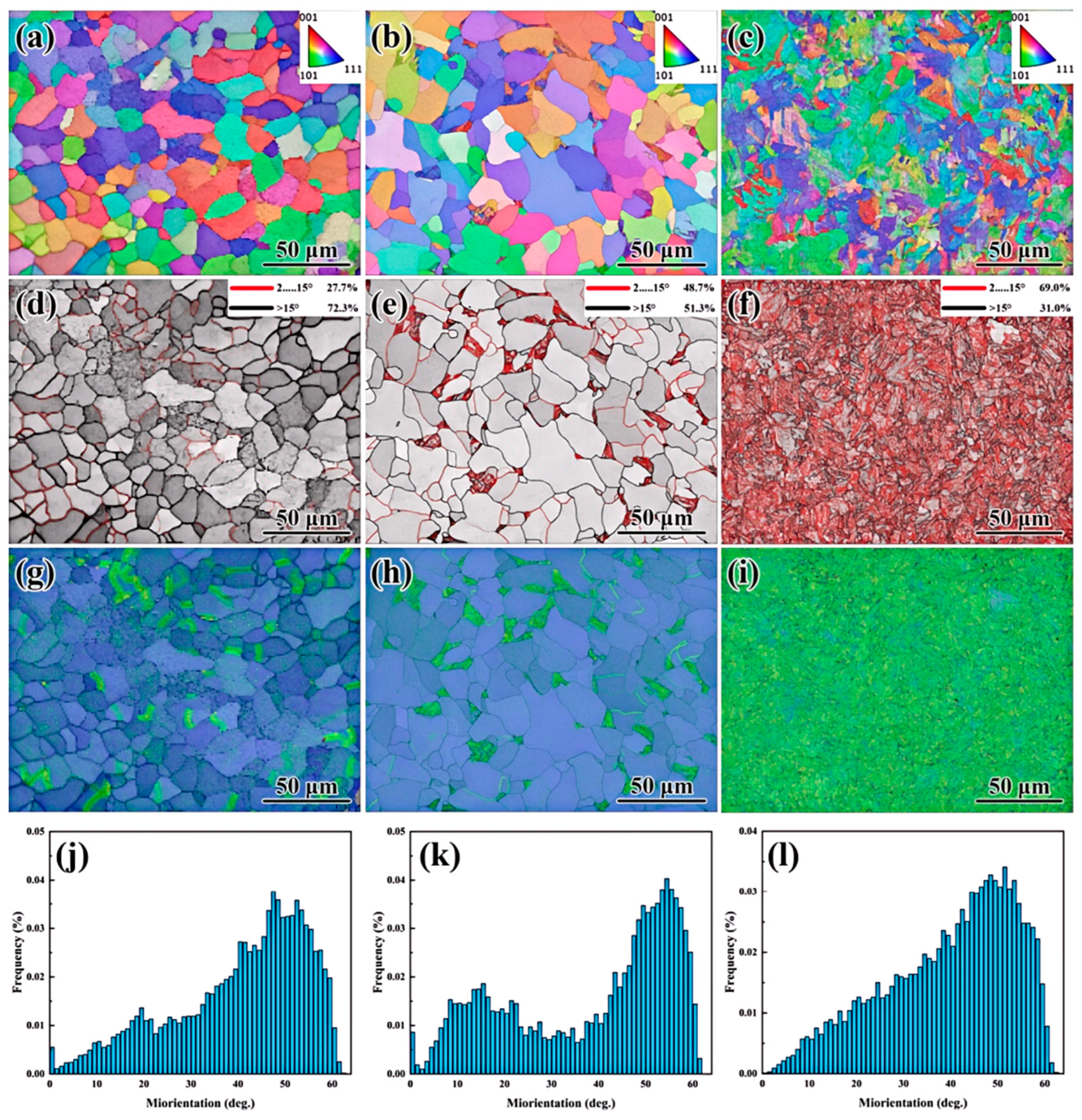
Electron backscatter diffraction (EBSD) was employed to analyze the misorientation angles and grain boundary character distribution (GBCD) in UCSS. The results are presented in
Figure 12. The room-temperature microstructure, shown in
Figure 8, consists primarily of polygonal ferrite (PF), acicular ferrite (AF), and bainitic ferrite (BF).
Figure 12a–c present the grain orientation distribution along the rolling direction in UCSS. From these figures, it is evident that distinct phases exhibit minimal misorientation differences. Acicular ferrite (AF) laths that are parallel to each other show similar orientations, while those crossing at an angle exhibit different orientations. The length of the acicular ferrite laths is approximately 5–10 μm, as shown in
Figure 12e. The bainitic ferrite (BF) laths within the presented region exhibit a consistent orientation. However, several ferrite grains with differing orientations appear within the bainitic ferrite lath grains. The width of these bainitic ferrite laths is less than 5 μm, as shown in
Figure 12f. Within this specific region, the bainitic ferrite lath packets tend to share a uniform orientation. The observed phenomenon is attributed to the coarse proto-austenite grains formed during the CASTRIP process. This coarse prior austenite grain structure results in a reduction in grain boundary length, thereby decreasing both the nucleation sites and the nucleation rate for the transformation of supercooled austenite. Therefore, the transformation of bainitic ferrite nucleating at the grain boundaries occurs prior to transformations within the grain interiors.
The red lines represent low-angle grain boundaries (LAGBs) of 2~15°, and the black lines represent high-angle grain boundaries (HAGBs) of >15°. It is seen in
Figure 12g–i that polygonal ferrites were dominated by high-angle grain boundaries, but only accounted for about 10% in UCSS. Acicular ferrite and bainite ferrite were dominated by low-angle grain boundaries, accounting for 77.0% and 73.9%, respectively. The high frequency of low-angle grain boundaries indicates the existence of a large number of substructures, which were also observed in the TEM image in
Figure 11. Low-angle grain boundaries had low energy and strong binding force, and are not easily exchanged with solute atoms and dislocations, which could reduce or prevent the generation of microcracks, and these low-energy grain boundaries can hinder the propagation of microcracks [
41].
3.4. Microstructure Characteristics of Heat-Treated Specimens
TEM micrographs for the typical bainitic ferrite morphologies of the 2#-3# specimens are shown in
Figure 13. The bainite ferrite of the three specimens nucleated from the grain boundary, similar to the bainite nucleation mechanism of UCSS. The bainite ferrite content in the air-cooled specimen is very low, and the width of the bundle is about 529 nm, which is mainly sandwiched at multiple polygonal ferrite interfaces (
Figure 13a). The size of lath bundles of bainite ferrite in the specimens after water cooling and brine cooling appears larger. A small quantity of fine polygonal ferrite formed prior to the development of bainite ferrite in the water-cooled specimen (
Figure 13b), while in the brine-cooled specimen, the bainite ferrite developed almost perpendicularly to the grain boundaries (
Figure 13c).
EBSD analysis of heat-treated UCSS steel characterized grain misorientation, grain boundary orientation distribution, and geometrically necessary dislocation (GND) density (
Figure 14). Inverse pole figure (IPF) maps for specimens 2#, 3#, and 4# (
Figure 14a–c) utilize red, green, and blue to denote <001>, <101>, and <111> orientations, respectively, where uniformly colored regions indicate grains with analogous crystallographic orientations. This revealed significant orientation variations among polygonal ferrite grains. In grain boundary orientation maps, red and black lines represented low-angle (2–15°, LAGBs) and high-angle (>15°, HAGBs) boundaries, respectively. Statistical analysis of grain misorientation (
Figure 14j–l) demonstrated a marked increase in 40–60° misoriented grains with decreasing polygonal ferrite content, primarily attributed to bainitic ferrite growth originating at polygonal ferrite interfaces.
As can be seen from
Figure 14d, the polygonal ferrite is predominantly characterized by high-angle grain boundaries (HAGBs), accounting for 72.3% in specimen 2#. On the contrary, as can be seen from
Figure 14e,f, the acicular ferrite and bainitic ferrite primarily exhibit low-angle grain boundaries (LAGBs), resulting in a 69.0% LAGB proportion in specimens 3# and 4#. As the volume fraction of polygonal ferrite decreases, the proportion of LAGBs increases while that of HAGBs decrease. The high frequency of LAGBs indicates abundant dislocation substructures within the microstructure, as evidenced in
Figure 13 and
Figure 14i. These low-energy grain boundaries possess low interfacial energy and strong binding forces, limiting exchange capacity with solute atoms/dislocations. Consequently, they effectively suppress microcrack initiation and hinder microcrack propagation [
42].
The microstructure comparison of the above heat treatment processes with the UCSS process shows that under ultra-fast cooling, acicular ferrite has a cross-interlocking structure and a high dislocation density, with fine grains (as shown in
Figure 3). Therefore, increasing the proportion of acicular ferrite can significantly enhance the yield strength. Moreover, the high grain boundary density of acicular ferrite makes it easier to arrest crack propagation or cause the main and secondary cracks to undergo large-angle deflection in the previous propagation direction [
13,
14], thereby improving the toughness of UCSS. Meanwhile, bainitic ferrite also has a high dislocation density and makes a significant contribution to strength, but it reduces the plasticity of the steel. On the other hand, polygonal ferrite is a soft phase with good plasticity. This is the reason why UCSS steel has high strength under ultra-low-carbon conditions and also possesses acceptable plasticity. In UCSS, bainitic ferrite has the highest dislocation density, and its laths are relatively coarse, with a small amount of cementite usually distributed between the laths. This is the main reason for the increase in strength and the decrease in plasticity. Therefore, for a good strength–plasticity balance, the content of bainitic ferrite needs to be appropriately controlled, the volume fraction of acicular ferrite can be appropriately increased, and the volume fraction of polygonal ferrite should be adjusted according to the strength requirements. From the above summary, it can be concluded that the conditions for easily obtaining acicular ferrite are as follows: first, using fine and uniformly distributed spherical oxides; second, controlling the quenching cooling rate near the critical cooling rate of bainitic ferrite.
3.5. Influence of the Alloy Elements
The introduction of P and Sb elements into BCC steel is likely to produce grain boundary segregation, resulting in the reduction in the second type of tempered brittleness or impact toughness. In Fe-Sb alloys, the critical amount of Sb for grain boundary segregation is about 0.1% [
28,
30,
38]. Compared to other alloying elements, the segregation of Cu and Nb is slighter. Nb is prone to combine with C and N in steel to form fine and dispersed carbides, nitrides, or complex carbonitrides (such as NbC, NbN, or Nb(C,N)), which is the typical existence form of Nb in steel. Due to the relatively high solubility, Cu can be completely dissolved in the austenite region and partially dissolved in ferrite. When the solubility limit is exceeded, the ε-Cu phase will precipitate [
40,
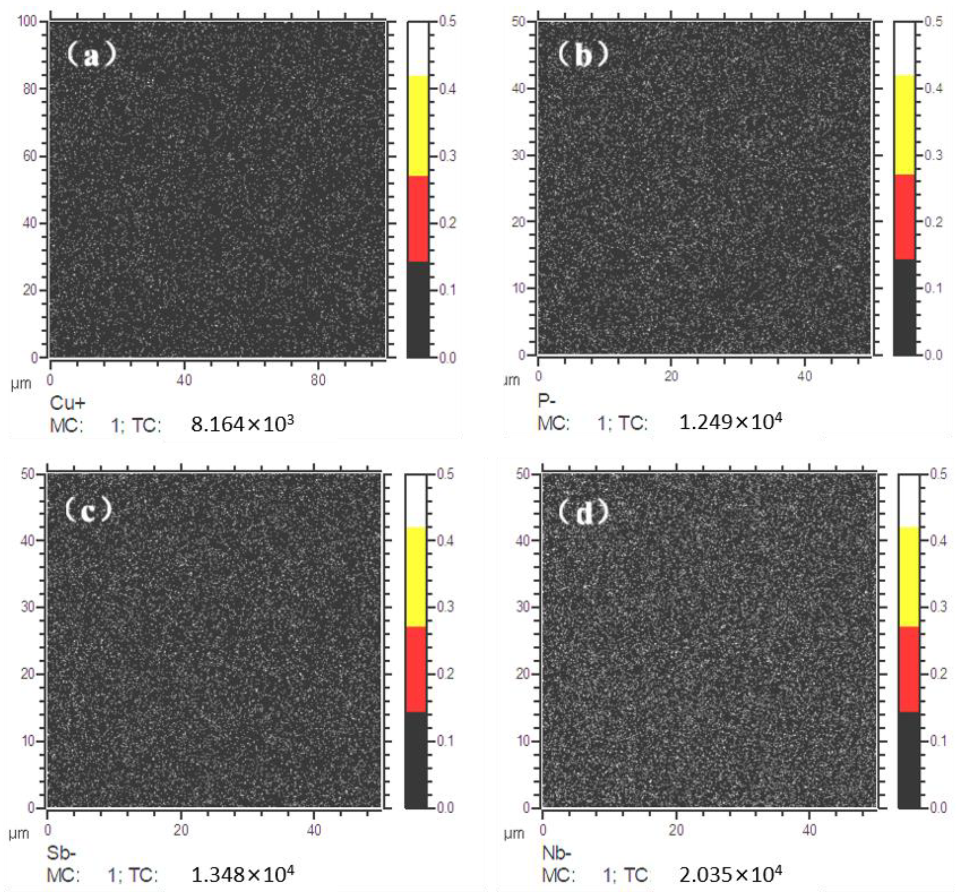
41]. Therefore, the solid solubility of Cu, P, Sb, and Nb elements in the matrix and at the grain boundaries was tested through SIMS. The results showed the distribution of Cu, P, and Sb elements at the grain boundaries of UCSS. As shown in
Figure 15a,b, the elements Cu, P, Sb, and Nb are uniformly distributed in the matrix (represented by small yellow spots in the image). P, Sb, and Nb exhibit more uniform solid solubility compared to Cu, with no significant segregation observed at the grain boundaries for all four elements. A trace amount of alloying elements is completely dissolved in the matrix under the ultra-fast cooling process, leading to solid solution strengthening. This is also an important feature of the CASTRIP process.
The cooling rate of traditional hot-rolled steel strips is relatively low, and alloy elements are prone to combine with C/N to form carbon nitrides, which consume the solute elements. Ultra-fast cooling enables the matrix to rapidly traverse the precipitation temperature range and prevents the corrosion-resistant elements such as Cu, P, and Sb from segregating at the grain boundaries, which not only prevents grain boundary brittleness but also ensures the uniform distribution of solute atoms [
43,
44]. Because of the low carbon content in UCCS, the contribution of precipitation strengthening is slight, while the contribution of solute strengthening becomes dominant [
43]. In low-alloy steel, the increase in strength caused by the solid solution of solute atoms can be expressed as Formula (1) [
45]:
where [M] represents the mass percentage of the uniform element. According to the spectral analysis of the UCSS specimen, the increment caused by solid solution strengthening is about 119 MPa. Evidently, the obtained high strength of UCSS steel is mainly associated with the phase transformation strengthening, dislocation strengthening, and solution strengthening.


