Article

Comparative Study on the Microstructure and Simulation of High-Speed and Conventional Fe-Based Laser-Cladding Coatings

by
Chuan Guo
1,
Shouwen Ding
2,
Xiaoqiang Xue
3,
Mingzhong Li
4,5,
Jingwang Yan
6,
Shubin Wang
6,
Dandan Wang
4,5,
Xiaotong Zhang
1,
Shuisheng Chen
7,
Liuhua Yang
8,
Zhenzhong Liu
3 and
Shirui Guo
2,*
1
Linzhou Heavy Machinery Group Co., Ltd., Anyang 456550, China
2
School of Intelligent Mechatronics Engineering, Zhongyuan University of Technology, Zhengzhou 450007, China
3
Shanxi Xiaobaodang Mining Co., Ltd., Yulin 710018, China
4
China Coal Technology & Engineering Group, Beijing 100013, China
5
State Key Laboratory of Digital and Intelligent Technology for Unmanned Coal Mining, Anhui University of Science and Technology, Hefei 232001, China
6
Shanxi Coal Group Shenmu Ningtiaota Mining Co., Ltd., Yulin 719314, China
7
School of Mechanical and Power Engineering, Henan Polytechnic University, Jiaozuo 454000, China
8
School of Civil Engineering, Henan Polytechnic University, Jiaozuo 454000, China
*
Author to whom correspondence should be addressed.
Crystals 2025, 15(6), 545; https://doi.org/10.3390/cryst15060545
Submission received: 6 May 2025 / Revised: 19 May 2025 / Accepted: 4 June 2025 / Published: 6 June 2025
(This article belongs to the Section Inorganic Crystalline Materials)

Abstract

High-speed and conventional laser cladding technologies were used to prepare Fe-based alloy cladding layers on the surface of 45 steel, compare and analyze the microstructure, microhardness, and phase structure of the two cladding layers, and study and analyze the morphology of the molten pool under the two cladding technologies, as well as the mechanism of evolution of the microstructure of the molten pool during the solidification process. The results show that, compared with the conventional laser melting coating, the grain size of the high-speed laser melting coating is finer, and the cooling rate at the top for conventional laser melting is 5.72 × 10³ K/s, and the cooling rate for high-speed laser melting is 3.53 × 10⁵ K/s. The microhardness of the high-speed laser melting coating has been significantly improved, and the solidification rates at the top for the two types of laser melting are the highest, namely 5.84 mm/s and 24.7 mm/s; the molten pool in conventional laser melting is usually larger and deeper, presenting a wide and deep shape, whereas the high-speed laser molten pool is usually shallower and narrower, with a flatter shape, presenting a comet trail, and the fast-cooling and fast-heating effects of high-speed laser melting are more significant.

1. Introduction

Laser cladding, as an advanced surface modification technique, has been widely applied in modern industry, particularly in the field of mining machinery [1]. For the cutter disc, a core component in mining operations, 45 steel has been widely adopted as the substrate material for mining cutterheads due to its favorable strength–toughness balance and exceptional fatigue resistance, which ensure structural integrity under complex loading conditions [2]. The cutter disc is under harsh conditions of high impact and severe wear, necessitating high hardness and extended service life [3]. A high-hardness coating can be formed on the surface of the cutterhead through laser cladding technology, significantly enhancing its surface hardness and wear resistance [4,5,6]. However, as mining operations demand increased intensity and speed, conventional laser cladding shows certain limitations in meeting the performance requirements for high-speed cutting conditions and usually requires longer processing times, which cannot fully meet the demands of rapid industrial manufacturing. In recent years, extensive research has been conducted on laser cladding technology. Due to the maturity of conventional laser cladding processes and their good cladding performance, they have been widely adopted. Studies have shown that the microstructure of Fe-based coatings produced by laser cladding directly impacts their mechanical properties. By optimizing cladding process parameters, the hardness and wear resistance of the coatings can be significantly improved [5,6,7].
In 2017, the Fraunhofer Institute for Laser Technology (ILT) and RWTH Aachen University in Germany jointly developed ultra-high-speed laser cladding technology [8]. This approach significantly enhances cladding efficiency and powder utilization, thereby increasing productivity and reducing costs. Ultra-high-speed laser cladding outperforms conventional processes in energy efficiency and cladding speed, offering shorter production cycles while further improving the cutter disc’s surface performance. Therefore, systematically studying the differences in microstructure and hardness between Fe-based coatings produced by high-speed and conventional laser cladding is crucial for optimizing surface modification techniques for mining cutter discs. Zhou et al. [9] employed both conventional low-speed laser cladding and high-speed laser cladding to deposit Ni45 powder on steel substrates, discovering that the cooling rate in conventional cladding was lower than that in high-speed cladding, with the cooling rate increasing as cladding speed increased. Ding et al. [10] fabricated Inconel625 coatings on 27SiMn steel using both ultra-high-speed laser cladding and conventional low-speed cladding, finding that the ultra-high-speed cladding exhibited more severe element segregation. They also noted that increasing cladding speed significantly enhanced the hardness, wear resistance, and corrosion resistance of Inconel625 coatings. Xu Yifei et al. [11] successfully fabricated high-quality iron-based alloy coatings on 45 steel substrates via high-speed laser cladding. The coatings were primarily composed of ferrite and austenite phases, demonstrating a microhardness approximately three times higher than that of the substrate.
The microstructure and properties of coatings are significantly influenced by laser parameters such as power and cladding speed. During the cladding process, these process parameters have a decisive impact on the shape of the melt pool, the cooling rate, and ultimately, the microstructure of the resulting coating. However, the complexity of the cladding process, involving interactions between multiple physical fields, makes it difficult to fully understand how these process variations affect coating performance through experimental methods alone. As a result, numerical simulation technology has emerged as an effective tool for studying laser cladding processes. Through simulations, not only can the temperature field distribution, melt pool morphology, and cooling process be accurately modeled, but the microstructural evolution under different process conditions can also be predicted. For example, Hang et al. [12] applied ultra-high-speed laser cladding on 25CrMo4 steel and used numerical simulations to investigate the thermal effects on the substrate, revealing a gradient change in microstructure from the cladding interface to the top, similar to that of conventional laser cladding. This paper focuses on the preparation of Fe-based coatings on 45 steel using both conventional and high-speed laser cladding technologies. The coatings are analyzed under different process conditions to compare their microstructure, phase composition, and hardness. Additionally, a detailed comparative analysis of numerical simulations for both high-speed and conventional laser cladding is conducted. This study explores the differences in temperature fields and melt pool morphologies between the two cladding methods, which are then validated through experimental results. The findings further explain how these differences impact the microstructure and hardness of Fe-based coatings. The aim of this research is to provide theoretical support for optimizing laser cladding processes and offer scientific evidence for improving the performance of Fe-based coatings in practical applications.

2. Cladding Experiment

2.1. Substrates and Materials

The experiment utilized 45 steel, a material commonly used in cutter discs in coal mining, as the substrate. The dimensions of the substrate were 200 mm × 60 mm × 20 mm. The chemical composition of the 45 steel is provided in Table 1.
Due to the faster cladding speed of high-speed laser cladding, the amount of powder melted per unit time is significantly greater than that in conventional laser cladding [13]. This necessitates stricter requirements for powder particle size and powder feeding speed. Therefore, smaller particle-sized alloy powders were used in high-speed laser cladding to enhance powder feeding efficiency and melting efficiency. There is a significant difference in the particle size of the Fe-based alloy powders used for high-speed and conventional laser cladding. The Fe-based alloy powders for both processes were purchased from the Shenyang Institute of Rare Metals. The particle size range for the Fe-based alloy powder used in conventional cladding was 53.26 to 150.43 µm, with an average diameter of 92.44 μm, while for high-speed laser cladding, it was 38.16 to 53.84 µm with an average diameter of 46.51 μm. Both iron-based alloy powders with distinct particle size ranges were fabricated via high-pressure gas atomization. The chemical composition of the Fe-based alloy powders is shown in Table 2.

2.2. Experimental Equipment

The conventional laser cladding experiment utilized an LDM8060 high-power semiconductor fiber-coupled laser (spot diameter: 3 mm) and a four-channel coaxial powder feeder (model RC-PGF-D-2) equipped with dual vacuum hoppers, both manufactured by Nanjing Zhongke Raycham Laser Technology Co., Ltd., Nanjing, China. A MCWL-150DT2 water chiller from Tongfei (Hebei, China) was employed to provide circulating cooling water for the laser and the external optical system, while nitrogen gas was used to protect the laser head and cladding environment. For the high-speed laser cladding experiment, the experiment utilized a flexible robotically controlled high-speed laser cladding system, model iLAM®25Fpt-600, as the experimental apparatus. The system is equipped with a 6000 W domestically produced multimode fiber laser with a preset laser beam diameter of 3 mm. The high-speed laser cladding experiments were conducted using the HR-WPFH-DT1H06 model laser cladding synchronized turntable double-barrel powder feeder manufactured by Nanjing Huirui Photoelectric Technology Co., Ltd., Nanjing, China, employing a coaxial annular powder feeding method. Additionally, nitrogen gas with a purity of 99.99% was used for molten pool protection. To compare the performance of coatings produced by high-speed and conventional laser cladding, one set of optimized conventional laser cladding parameters and three sets of high-speed laser cladding parameters with different cladding speeds were selected. The experimental parameters are listed in Table 3.

2.3. Test and Characterization Methods

The coating samples were prepared using wire electrical discharge machining (WEDM). After grinding and polishing, the samples were ultrasonically cleaned in anhydrous ethanol and dried before being etched with aqua regia solution. Microstructure observations were conducted using a JSM-7800F scanning electron microscope (SEM). The system is equipped with a Quantax75 Energy Dispersive Spectroscopy (EDS) analyzer. The microhardness of the cross-section of the cladding layer was measured using an HVS-5Z digital Vickers hardness tester. The applied load was 200 g, with a dwell time of 10 s. Measurements were taken along the depth of the coating, with intervals of 50 µm between each measurement point. Phase analysis of the coatings was performed using an XRD-6000 X-ray diffractometer, with a scanning range of 20° to 80° and a scanning speed of 2°/min.

3. Laser Cladding Temperature Field Simulation

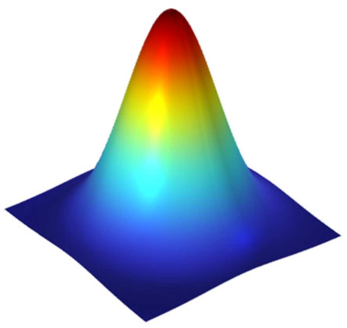
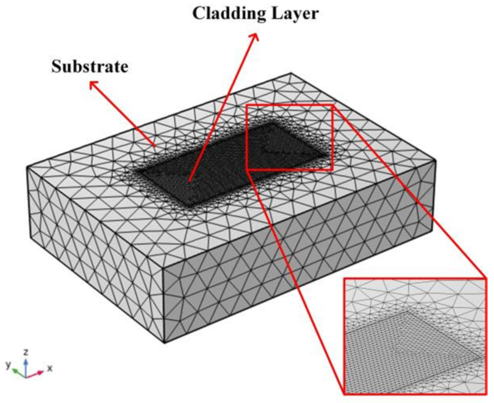
Heat Transfer Model with Phase Change and Heat Source Modeling

In this paper, the finite element method was employed to simulate the cladding process of Fe-based alloy powder on a 45 steel substrate, aiming to investigate the dynamic evolution of the temperature field during cladding. The following basic assumptions were made for this paper based on the characteristics of the research subject: (1) the thermal action of the temperature field conforms to the classical heat transfer theory; (2) the material is isotropic during cladding; (3) the effects of fluid flow within the melt pool and material vaporization at high temperatures are neglected [14]. The heat transfer process during the laser cladding can be described using the heat transfer equation, given as
ρ c T t = x ( K x T x ) + y ( K y T y ) + z ( K z T z ) + Q
with ρ : density of the material (kg·m−3), as a function of temperature; c : specific heat capacity of the material (J·kg−1·K−1), as a function of temperature; T : distribution function of the temperature field (K); t : heat transfer time(s); K x ,   K y ,   K z : thermal conductivity units in the x ,   y ,   z directions, respectively; Q : internal heat source, including phase change latent heat and heat source load (J).
The primary difference between high-speed laser cladding and conventional laser cladding lies in the defocusing of the laser beam. During defocusing, the energy of the laser beam experiences attenuation compared to the laser beam used in conventional cladding processes [15]. According to the Beer–Lambert law, the power of the attenuated laser beam is represented by
q l ( r , l ) = q l ( r ) exp σ e x t N l
with q l ( r , l ) : power levels after laser attenuation; T : boundary surface temperature of the object; T 0 : ambient medium temperature.
To simulate heat transfer during the cladding process, appropriate boundary conditions were established, including convective and radiative heat losses. In high-speed laser cladding, heat loss occurs primarily through convective cooling because of the rapid scanning speed. Conversely, in conventional laser cladding, where the scanning speed is lower, radiative cooling may also need to be considered. The initial condition was set to room temperature (300 K), and the thermal accumulation effects were adjusted through multiple simulations to ensure that the results were aligned with the actual conditions.
The basic form of heat transfer by convection can be described by Newton’s cooling equation [16]:
q c o n v = h T T 0
with h: heat transfer and convection coefficient; T: boundary surface temperature of the object; and T0: medium ambient temperature.
The Stefan–Boltzmann law guides the calculation of thermal radiation [17]:
q r = σ ε T 4 T 0 4
with ε : surface emissivity of the material; σ : Boltzmann constant.
In the laser cladding process, the laser heat source irradiates the substrate surface with a small spot size, and high-density laser energy disperses from the center of the laser spot towards the periphery. The energy density distribution of the laser heat source can be approximated by a Gaussian surface energy density model, which follows a normal distribution. The energy density formula for this model is given by the following [18]:
q   ( r )   = 2 P π r b 2 · exp 2 r 2 r b 2
with P: laser power; rb: radius of action of the laser beam; r: distance to the laser beam center.
As shown in Figure 1, the Gaussian heat source model was used to describe the energy distribution of the laser heat source. In this model, the energy density of the laser spot decreased gradually from the center outward, forming a bell-shaped distribution curve. The energy density was highest at the center and decreased as the distance from the center increased, resulting in a Gaussian-type distribution. This model simulates the actual energy distribution of a laser beam and provides a realistic representation of the distribution of laser energy over the material surface [19]. In numerical simulations of laser cladding, the Gaussian heat source model is one of the most commonly used surface heat source models. It accurately describes the energy distribution of the actual laser heat source and demonstrates how the laser energy varies with different process parameters.
The simulation model is illustrated in Figure 2. To ensure the accuracy of the simulation results while improving simulation speed, mesh refinement was performed on the coating and the adjacent substrate. Based on this refinement, a four-pass overlap experiment was conducted.
The materials of the substrate and the cladding layer were 45 steel and Fe-based alloy powder, respectively, and their thermophysical parameters are shown in Table 4 and Table 5.

4. Results and Discussion

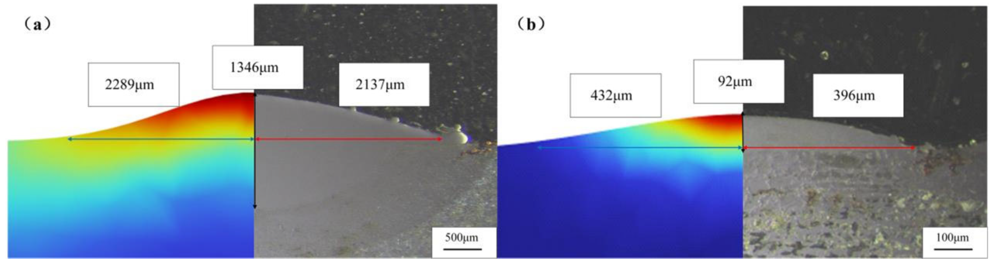
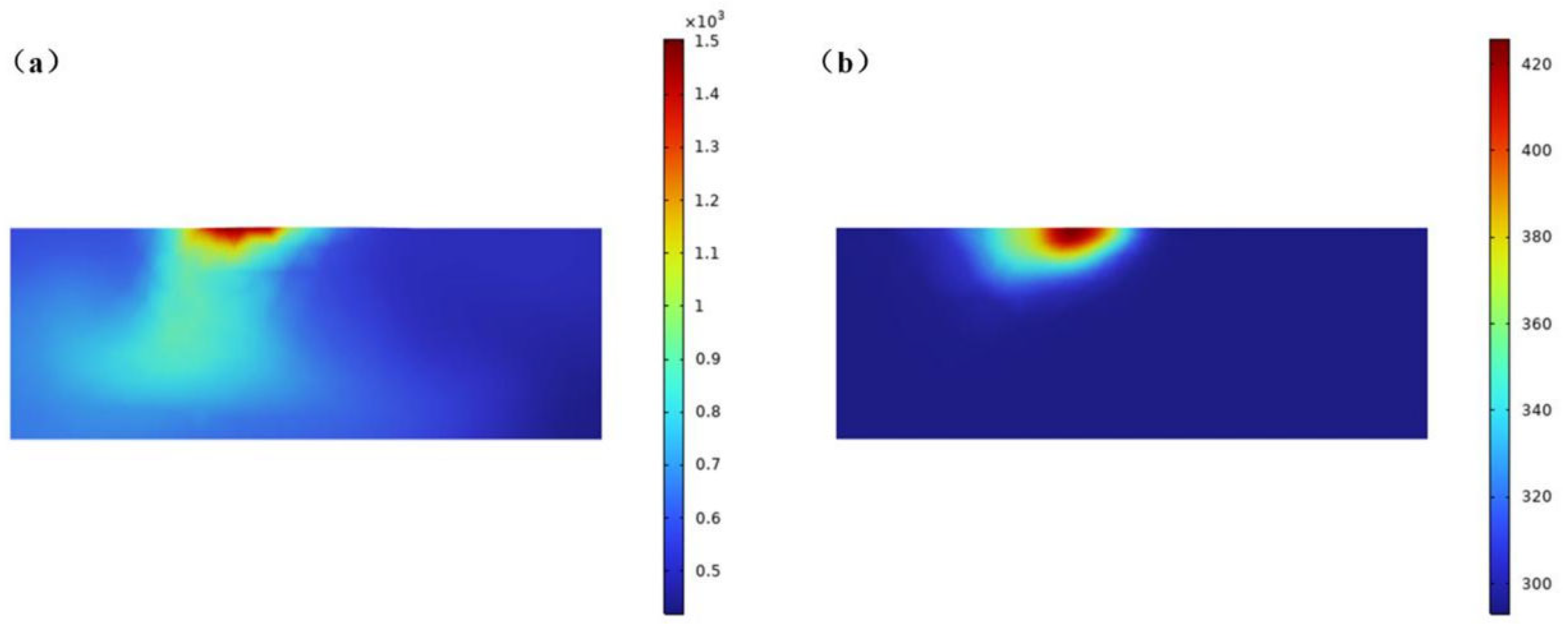
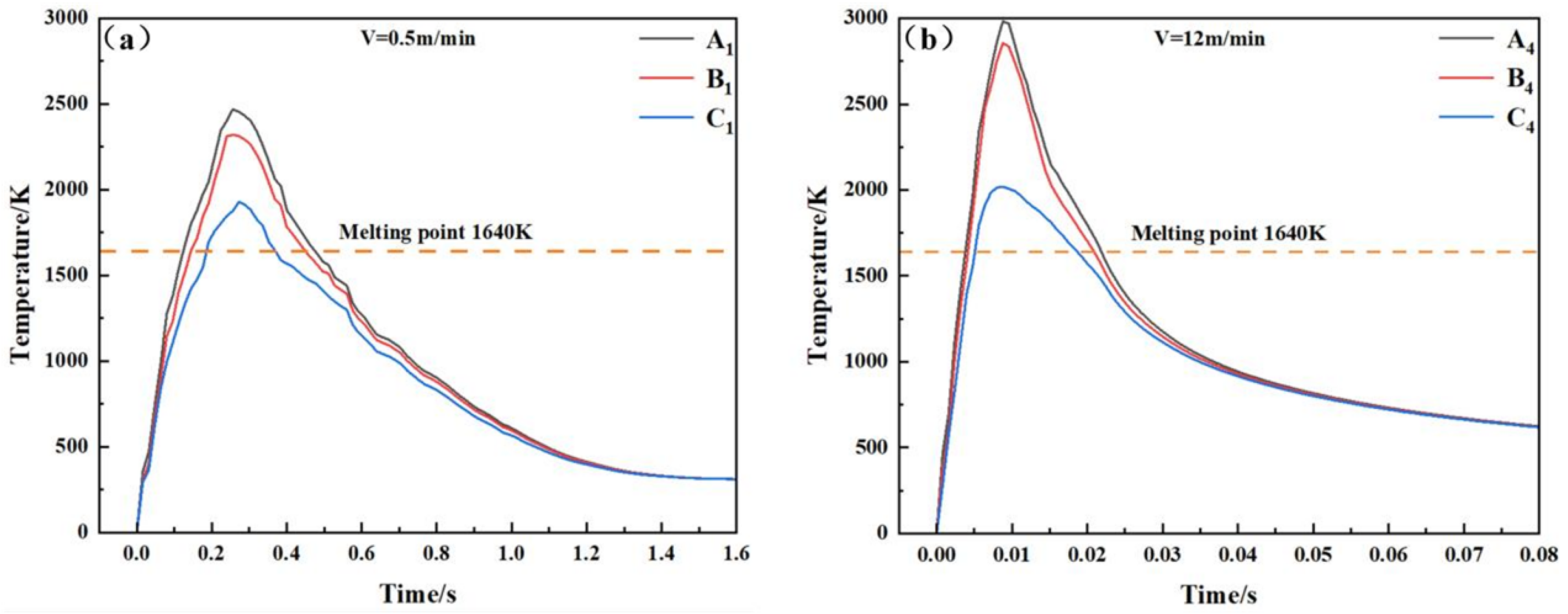
4.1. Numerical Simulation of Coating Temperature Field

Figure 3 presents the macroscopic morphology of cladding layers under two scanning speeds. As shown in Figure 3, the coating structures under both cladding speeds exhibit dense characteristics without defects such as pores or cracks.
Figure 4 compares the cross-sections of the simulated and experimental melt pools for both laser cladding techniques. The dimensions of the simulated melt pools are in good agreement with the actual melt pools, with a maximum error of 9.1%, which indicates that the temperature field simulation results are reasonably accurate. The comparison shows that the dilution rate for high-speed laser cladding is significantly lower than that for conventional laser cladding [20]. This difference is attributed to the fact that the laser energy is predominantly focused on the metal powder flow and the coating formed by the powder particles, thereby reducing the thermal impact of the laser source on the substrate.
Figure 5 illustrates the temperature field distributions for scanning speeds of 0.5 m/min and 12 m/min. It is observed that the melt pool area for conventional laser cladding is larger, with a more concentrated temperature distribution. The laser beam, operating at a lower scanning speed, resulted in a larger and deeper melt pool, characterized by a broad and deep shape. This extended formation time allowed the molten metal to mix thoroughly with the substrate, leading to a thicker metallurgical bonding layer. The slower cooling rate of the melt pool facilitates the formation of coarse grains within the coating, which may result in a less uniform microstructure, consistent with the characteristics of conventional laser cladding. In contrast, the high-speed laser melt pool is typically shallower and narrower, exhibiting a flatter, comet-like shape. As the cladding progresses, the comet tail extends owing to the rapid scanning speed, which shortens the time in which the laser energy is in contact with the substrate, leading to there being less time for the coating to cool. This is contrary to the characteristics of conventional laser cladding. At equilibrium, the temperature for conventional laser cladding stabilizes around 2400 K, while for high-speed laser cladding, it stabilizes around 3200 K. This difference is due to the shorter contact time of the laser beam with the material in high-speed laser cladding concentrating the laser energy on the substrate surface and causing a rapid increase in temperature. Conversely, in conventional laser cladding, the slower movement allows energy to be gradually transferred to deeper layers, resulting in a relatively lower maximum temperature. Figure 6 shows the temperature field cross-section at the end of the fourth cladding pass. It is evident that the temperature at the end of cladding for conventional laser cladding is 1520 K, whereas for high-speed laser cladding, it is 428 K. This indicates that the cooling rate for high-speed laser cladding is significantly faster than that for conventional laser cladding. In high-speed laser cladding, the heating and cooling processes are very brief, leading to a substantial reduction in the number of thermal cycles experienced by the coating and substrate. Compared to the slower heating and cooling of conventional laser cladding, high-speed laser cladding demonstrates a more pronounced instantaneous heating and cooling effect, reducing thermal accumulation and diffusion in the material, and significantly enhancing the rapid cooling and heating effects.

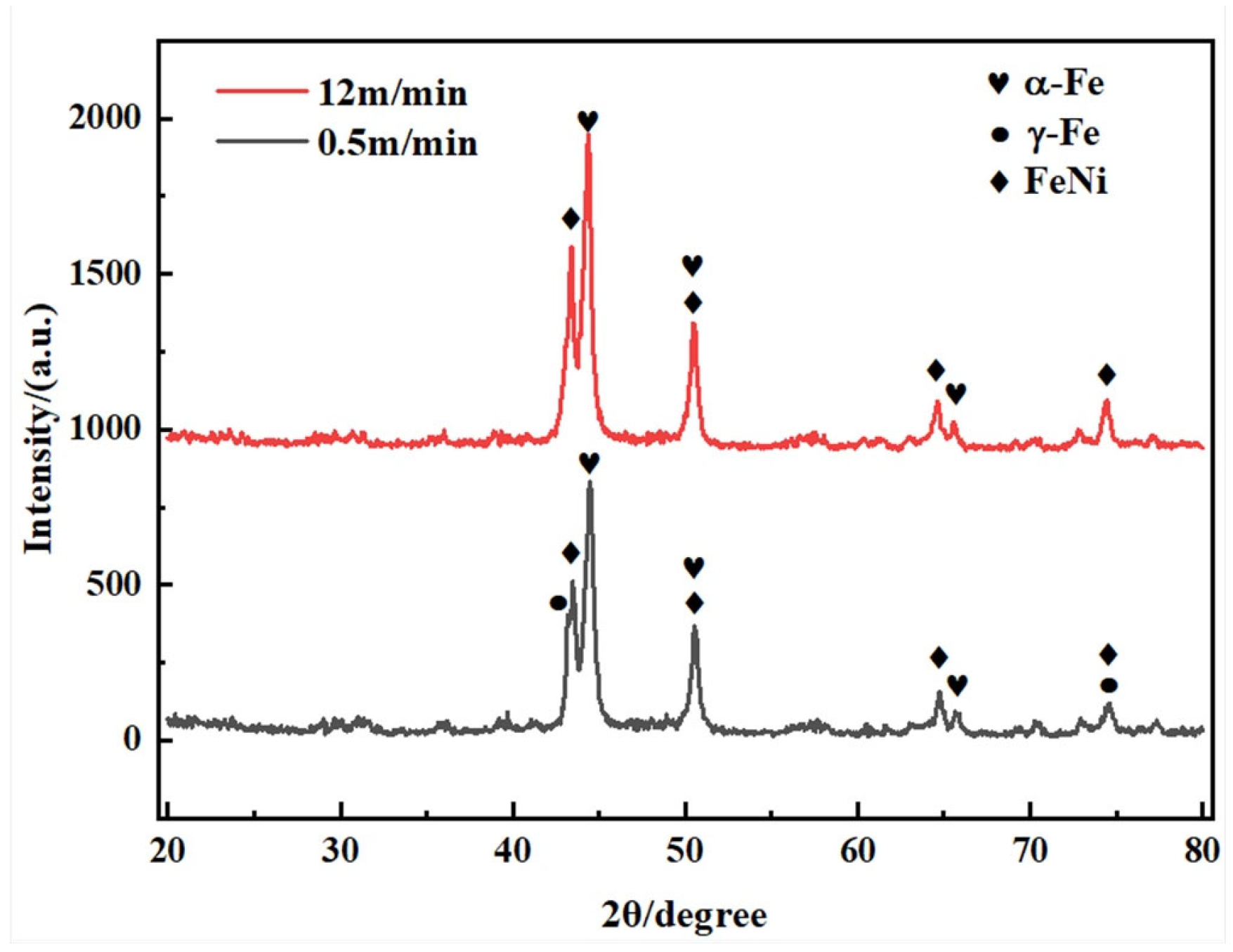
4.2. Phase Constitution
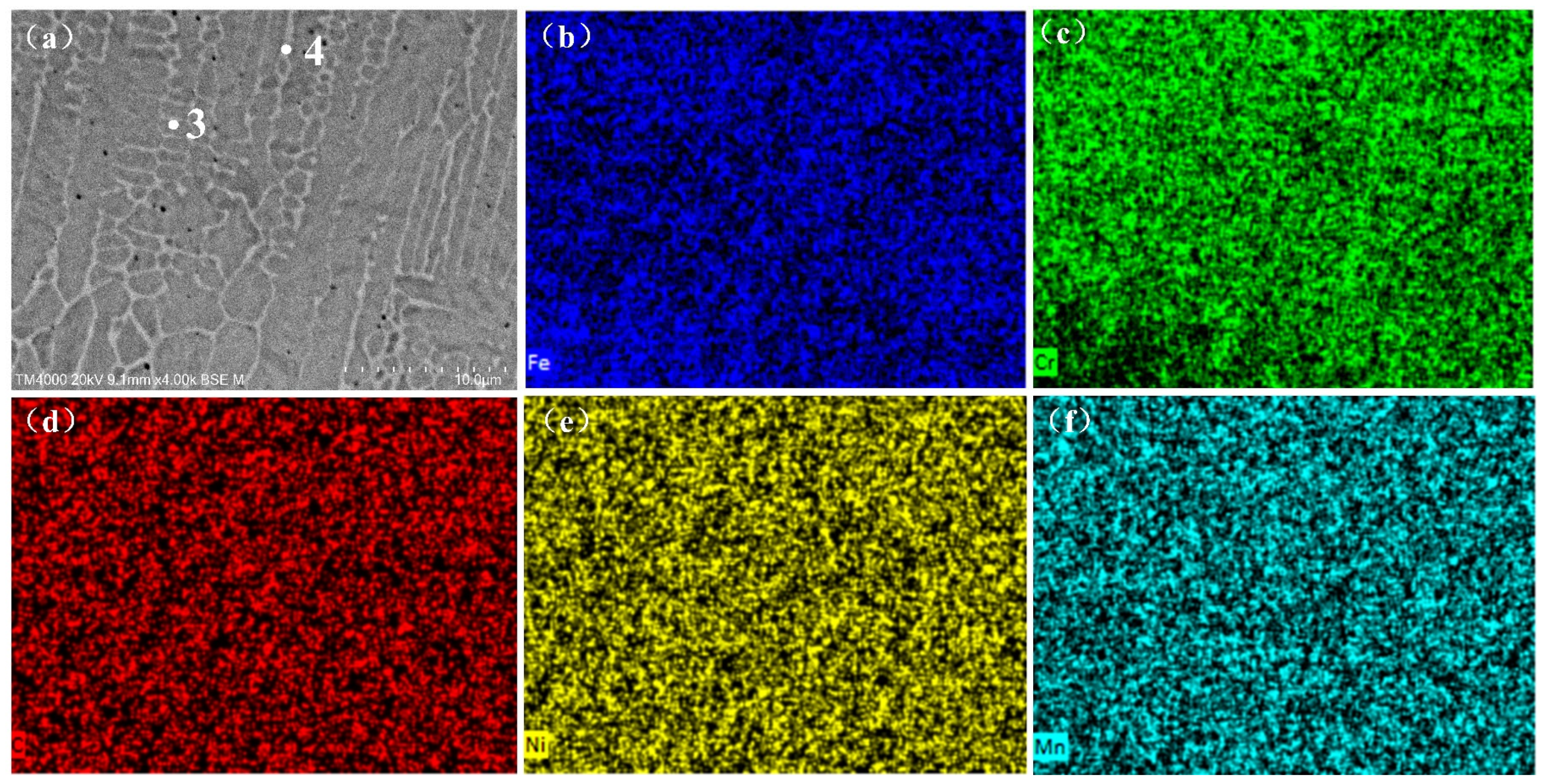
The characteristics of laser cladding include rapid heating and rapid cooling, resulting in non-equilibrium solidification. This non-equilibrium solidification leads to lattice distortion and the formation of supersaturated solid solutions within the solidified microstructure. Due to the significant difference in cladding speed between conventional laser cladding and high-speed laser cladding, the cooling rates of the coatings also differ considerably. This discrepancy in cooling rates may affect the phase composition of the cladded layers [21]. To investigate the phase differences between conventional laser cladding layers and high-speed laser cladding layers, X-ray diffraction (XRD) analysis was employed. The cladding speed for the high-speed laser cladding samples was 12 m/min, with the diffraction patterns shown in Figure 7. From Figure 7, it can be observed that the conventional laser cladding layers primarily consist of α-Fe solid solution, γ-Fe, and FeNi, while the high-speed laser cladding layers are composed mainly of α-Fe solid solution, Cr2B, and FeNi, with no new phases observed. According to the Fe-Cr-Ni ternary alloy solidification model [22], austenite (γ-Fe) is stable between 1183 K and 1667 K, and it forms as the primary phase from the liquid phase. Based on the solidification path, the possible sequence for the cladding layer is liquid phase→liquid phase + γ-Fe→γ-Fe→α-Fe. When the temperature of the melt pool drops to 910 °C, austenite (γ-Fe) transforms into ferrite (α-Fe). The absence of γ-Fe in the high-speed laser cladding layer is evident, as shown in Figure 8. The melt pool in high-speed laser cladding experiences γ-Fe stability for a very short time (1183~1667 K), resulting in a rapid transformation from γ-Fe to α-Fe [23]. Due to the elevated temperatures and rapid cooling rates inherent to laser cladding processes, the resultant austenite phase formed in iron-based powder alloy melts exhibits enhanced stability and subsequently undergoes a martensitic transformation at lower temperatures. In contrast, conventional laser cladding allows sufficient time for the formation of γ-Fe. In other words, the cooling rate in high-speed laser cladding is extremely high. As shown in Table 6, the magnitude of the cooling rate in high-speed laser cladding is 105, significantly higher than the 103 for conventional laser cladding. Furthermore, the primary diffraction peak of the α-Fe phase is positioned at approximately 44°, with high-speed laser cladding exhibiting a reduced diffraction angle for the α-Fe phase compared to conventional laser cladding. This reduction is due to the high cooling rate, which induces significant residual stresses within the material. These stresses cause lattice distortion, resulting in a slight increase in the interplanar spacing of the α-Fe phase and a shift of the diffraction peak to a lower-angle position [24]. As evidenced by the EDS mapping results in Figure 9 and Figure 10, the figures shows the elemental distribution in the dendritic regions (Points 1 and 3) and eutectic regions (Points 2 and 4) of the two laser cladding coatings, Cr exhibits significant enrichment within the eutectic regions of interdendritic zones, whereas Fe predominantly concentrates in dendritic areas. The high cooling rate effectively suppresses solute atomic diffusion, leading to solute trapping and non-equilibrium solidification. Consequently, Cr atoms are immobilized within the eutectic zones due to restricted diffusion from eutectic to dendritic regions, resulting in the formation of a more homogeneous supersaturated solid solution.

4.3. Microstructure

The microstructural characteristics of the cladding layer directly determine its performance [25]. Studying and analyzing the microscopic structure evolution mechanism during the solidification of the melt pool can help control the grain size of the cladding layer and, consequently, its performance. To investigate the impact of key thermal variables on grain morphology and the distribution of solidification characteristics in different regions, temperature gradients (G) and solidification rates (R) were obtained at the top (point A), middle (point B), and bottom (point C) of the cladding track, as shown in Figure 11. Parameters such as G/R and G×R were selected to predict solidification modes and crystal sizes. The variations in solidification parameters (G, R, G/R, and G×R) with time for both conventional laser cladding and high-speed laser cladding layers are summarized in Table 6.This paper analyzes the microstructure of the coating in the top, middle, and bottom regions. Figure 12, Figure 13 and Figure 14 illustrate the microstructure of the cladding layers under different laser scanning speeds.
The cooling rate (G×R) determines the size of the microstructure, with faster cooling rates resulting in smaller microstructures. The parameter G/R dictates the morphology of the microstructure: larger G/R values correspond to planar grains, intermediate values correspond to dendritic or cellular grains, and smaller values correspond to equiaxed grains. In the table, the cooling rate at the top for conventional laser cladding is 5.72 × 10³ K/s, while for high-speed laser cladding it is 3.53 × 10⁵ K/s. The cooling rate difference between the two methods spans two orders of magnitude, indicating that the grain size in high-speed laser cladding is significantly smaller than that in conventional laser cladding [26]. Both methods have the lowest G/R values at the top of the cladding. In Figure 12, the top of the coating mainly exhibits equiaxed grains. Both laser cladding techniques show uneven crystal growth directions at the top, due to changes in heat dissipation and the increased nucleation sites, leading to a disordered growth direction and irregular, isotropic characteristics. Because the upper part of the melt pool is exposed directly to the atmosphere, heat dissipation occurs relatively quickly, resulting in higher cooling rates (G×R) at the top of the coating. The conventional laser cladding top forms coarser equiaxed grains, while the high-speed laser cladding top forms finer equiaxed grains. As the cladding speed increases, the grains become progressively finer. For instance, at a cladding speed of 10 m/min, the extremely high cooling rate prevents dendrites from undergoing a columnar-to-equiaxed transition (CET) before solidification is complete. Moreover, fine grains formed by heterogeneous nucleation and microstructural undercooling also contribute to microstructural changes [27].
The microstructure in the middle of the coating, as shown in Figure 13, reflects that due to heat accumulation, heat dissipation slows down gradually. The G×R value in the middle is lower than at the top, indicating a slower cooling rate and larger microstructural dimensions. The grains in the middle form dendritic structures with a more consistent growth direction along the heat dissipation direction, displaying continuous epitaxial growth characteristics. There is a noticeable layering effect from the overlapping regions, with dendrites growing roughly perpendicular to the overlapping fusion lines. Dendritic structures show slight coarsening at each thermal overlap zone.
The microstructure at the bottom/base interface, shown in Figure 14, reveals that due to direct contact between the melt pool and the substrate, there is a large temperature gradient at this interface. However, the solidification rate is lower, with the composition undercooling approaching zero. The microstructure in this region grows as planar grains, with coarse columnar grains near the interface. These grains tend to grow perpendicular to the bottom/base interface due to the maximum temperature gradient perpendicular to the metallurgical bonding zone, which favors crystallization and growth [28].
The analysis results indicate that, regardless of the scanning speed, the microstructures of both conventional and high-speed laser-cladding coatings exhibit the same growth patterns, but with noticeable differences in the size of the microstructures. Overall, the microstructure of conventional laser-cladding coatings is relatively coarse, the equivalent average diameter of the coating grains is 3.60 μm, and the direction of dendritic growth is relatively disordered. In contrast, due to the unique technical characteristics of high-speed laser-cladding coatings, their microstructure is more refined and denser compared to that of conventional laser-cladding coatings [29], and the equivalent average diameter of the coating grains is 1.04 μm.

4.4. Hardness of Coating

Microhardness is considered a key indicator for evaluating the microstructure and mechanical properties of cladding layers [30]. The Vickers microhardness was measured along the vertical cross-section of the cladding layer samples. The hardness distribution of the Fe-based coatings for conventional and high-speed laser cladding is shown in Figure 11. The microhardness of the layer was divided into three regions: the coating, the heat-affected zone (HAZ), and the substrate. As illustrated in Figure 15, the hardness of both conventional and high-speed laser-cladding coatings is significantly higher than that of the substrate. Moreover, the hardness of the high-speed laser-cladding coatings exceeds that of the conventional laser-cladding coatings [31]. The average hardness of the conventional laser-cladding coatings is 406 HV0.5, approximately twice that of the substrate. For the high-speed laser-cladding coatings, the average hardness values are 569 HV0.5, 705 HV0.5, and 779 HV0.5, which are far higher than the substrate hardness values. The cladding layers produced by high-speed laser cladding have a larger grain boundary area compared to those produced by conventional cladding techniques. This results in more intense dislocation movement, which contributes to grain refinement and increases hardness [32]. As shown in Table 6, the highest solidification rates at the top of the cladding for both methods are 5.49 mm/s and 217 mm/s, with the solidification rate for high-speed laser cladding being several tens of times greater than that for conventional laser cladding [33]. Under elevated scanning speeds, the coating’s microstructure is refined with increased Cr dissolution within the dendritic regions. This microstructural evolution contributes to grain refinement strengthening and solid solution strengthening, thereby enhancing hardness. The surface hardness enhancement achieved through microstructural optimization demonstrates significant application value in coal mining cutterheads, effectively suppressing crack initiation and abrasive wear propagation under high-stress excavation conditions. This improvement is projected to substantially prolong the service lifespan of cutterheads, thereby enhancing equipment reliability and reducing maintenance costs in demanding mining operations.

5. Conclusions

  • The phase composition of conventional laser-cladding coatings is primarily α-Fe solid solution, γ-Fe, and FeNi. Owing to the extremely high cooling rates in high-speed laser cladding, γ-Fe rapidly transforms into α-Fe, resulting in no residual γ-Fe. The other phases remain the same as in conventional laser cladding, with no new phases emerging. The high cooling rate in high-speed laser cladding leads to significant formation of supersaturated α-Fe, causing the diffraction angle of α-Fe in high-speed laser-cladding coatings to be smaller than that in conventional laser cladding.
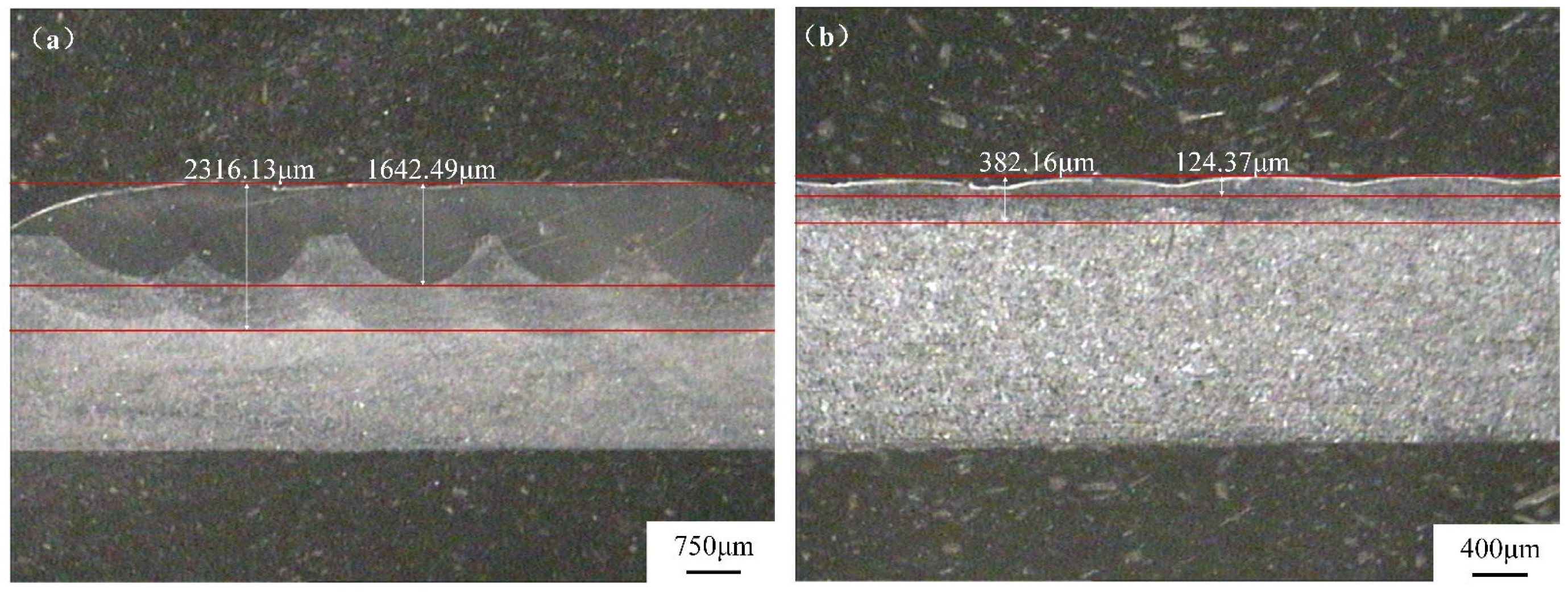
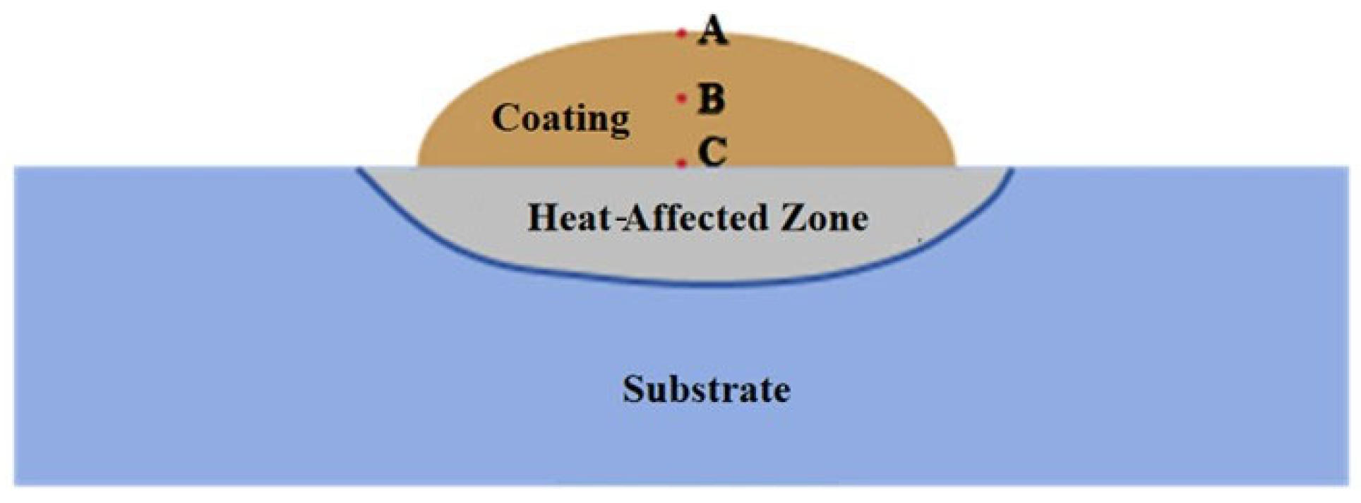
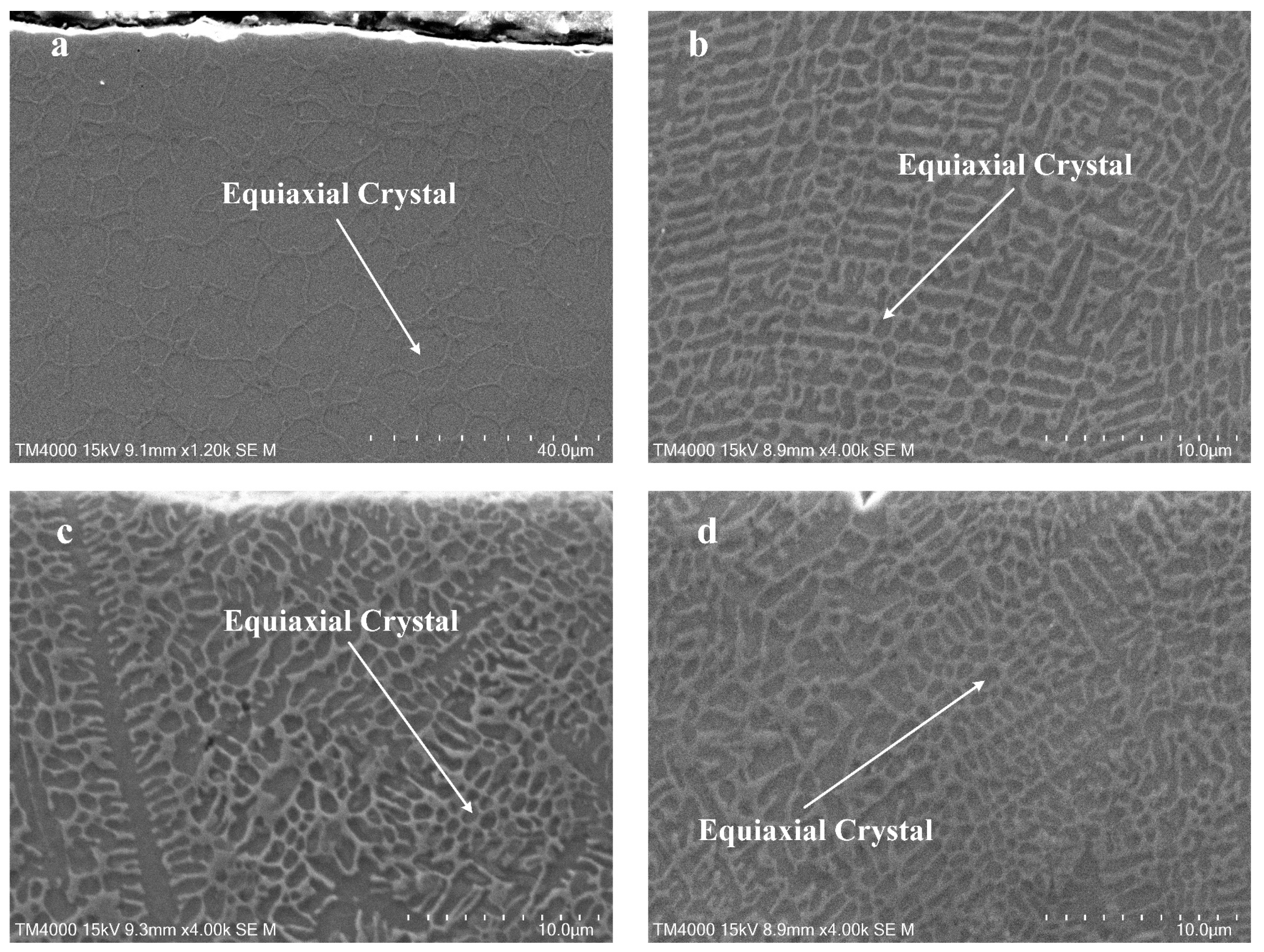
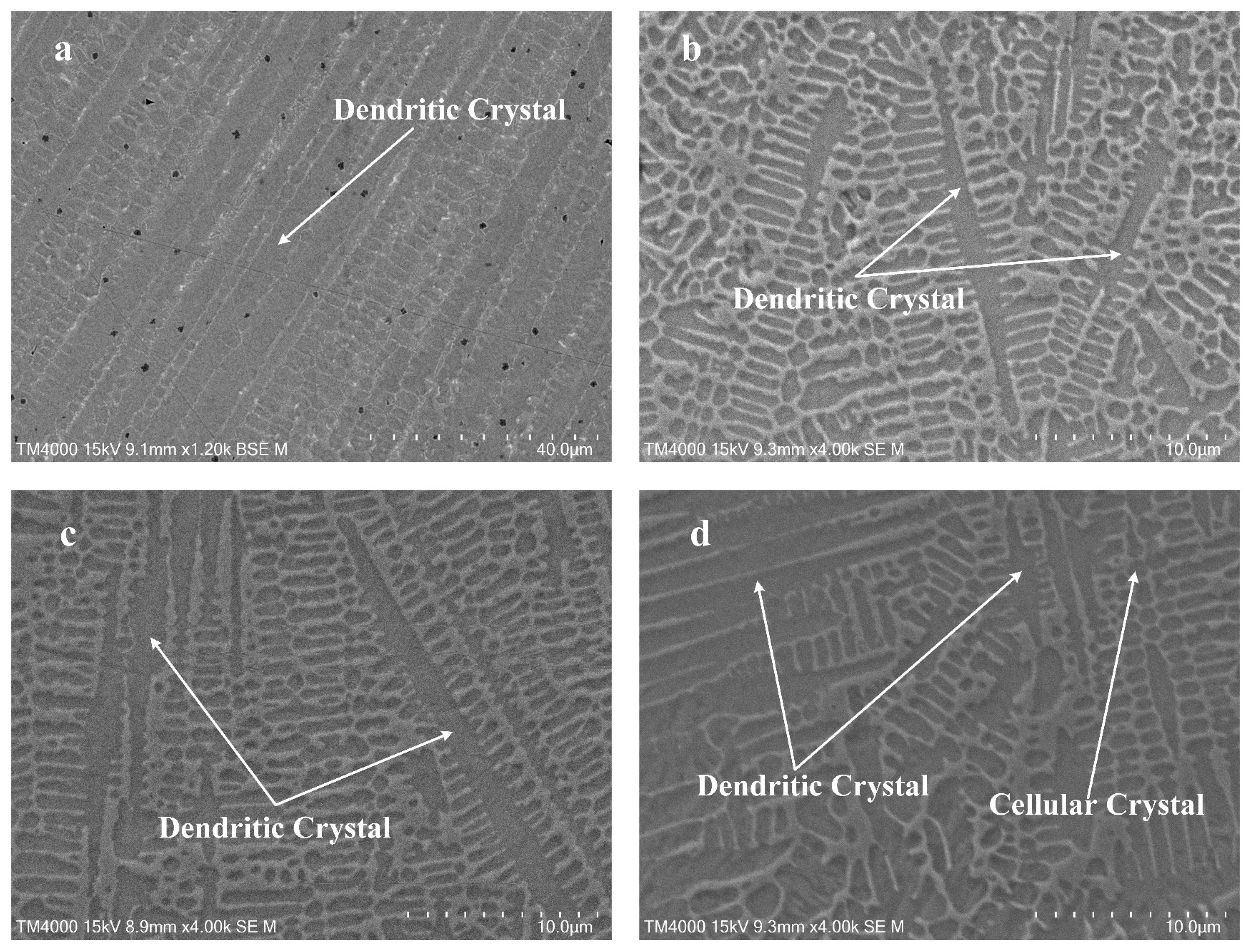
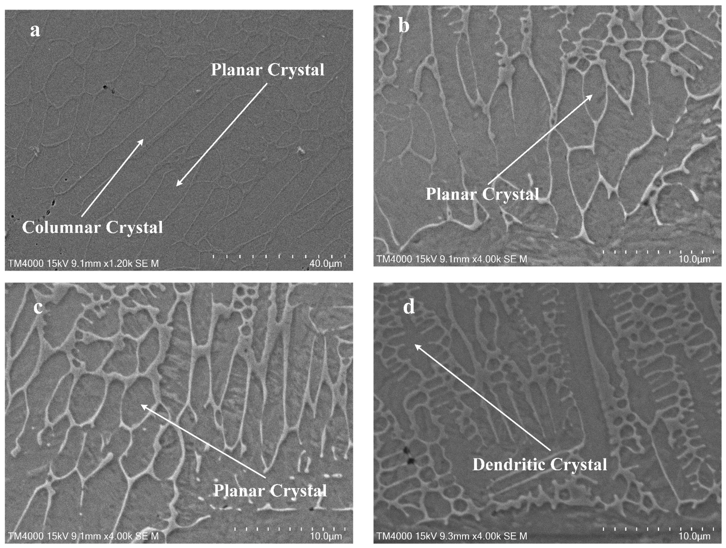
  • In both the conventional and high-speed cladding processes, the evolution of the microstructural morphology remained relatively consistent: the surface of the coating primarily consisted of equiaxed crystals, the middle of the coating featured dendritic structures, and the bottom of the coating was characterized by planar crystals and large columnar crystals. The grain size in high-speed laser cladding is significantly smaller than that in conventional laser cladding.
  • The hardness of both the conventional and high-speed laser-cladding coatings was significantly higher than that of the substrates. The average hardness of conventional laser-cladding coatings is 406 HV0.5, while the average hardness of high-speed laser-cladding coatings reaches 779 HV0.5 at a speed of 12 m/min. The solidification rate of high-speed laser cladding is several tens of times greater than that of conventional laser cladding. Consequently, the hardness of high-speed laser-cladding coatings is nearly twice that of conventional laser cladding, and the hardness of the coatings increases with cladding speed.

Author Contributions

C.G.: conceptualization, methodology, writing—original draft, funding acquisition. S.D.: formal analysis, writing—original draft, data curation, software. X.X.: visualization, supervision. M.L.: resources, project administration. J.Y.: validation, investigation. S.W.: funding acquisition, conceptualization, supervision. D.W.: supervision, resources. X.Z.: writing—review and editing, resources. S.C.: resources, project administration. L.Y.: supervision, resources. Z.L.: supervision, resources. S.G.: conceptualization, methodology, formal analysis, investigation, writing—original draft, funding acquisition. All authors have read and agreed to the published version of the manuscript.

Funding

This research was funded by the Key Scientific Research Project of Colleges and Universities in Henan Province grant number 24A460029, and this research was funded by the Postgraduate Education Reform and Quality Improvement Project of Henan Province grant number YJS2025XQLH24. The APC was funded by Key Scientific Research Project of Colleges and Universities in Henan Province.

Data Availability Statement

Data underlying the results presented in this paper are not publicly available but may be obtained from the authors upon reasonable request.

Conflicts of Interest

Authors Chuan Guo and Xiaotong Zhang were employed by the company Linzhou Heavy Machinery Group Co., Ltd. Authors Xiaoqiang Xue and Zhenzhong Liu were employed by the company Shanxi Xiaobaodang Mining Co., Ltd. Authors Mingzhong Li and Dandan Wang were employed by the company China Coal Technology & Engineering Group. Authors Jingwang Yan and Shubin Wang were employed by the company Shanxi Coal Group Shenmu Ningtiaota Mining Co., Ltd. The remaining authors declare that the research was conducted in the absence of any commercial or financial relationships that could be construed as a potential conflict of interest.

References

  1. Haldar, B.; Saha, P. Identifying defects and problems in laser cladding and suggestions of some remedies for the same. Mater. Today Proc. 2018, 5, 13090–13101. [Google Scholar] [CrossRef]
  2. Comakli, R.; Balci, C.; Copur, H.; Tumac, D. Experimental studies using a new portable linear rock cutting machine and verification for disc cutters. Tunn. Undergr. Space Technol. 2021, 108, 103702. [Google Scholar] [CrossRef]
  3. Manoj, A.; Saurabh, A.; Narala, S.K.R.; Saravanan, P.; Natu, H.P.; Verma, P.C. Surface modification of grey cast iron by laser cladding for automotive brake disc application. Wear 2023, 532–533, 205099. [Google Scholar] [CrossRef]
  4. Agrawal, A.K.; Chattopadhyaya, S.; Murthy, V.M.S.R.; Legutko, S.; Krolczyk, G. A novel method of laser coating process on worn-out cutter rings of tunnel boring machine for eco-friendly reuse. Symmetry 2020, 12, 471. [Google Scholar] [CrossRef]
  5. Zhang, D.; Li, Z.; Fan, H.; Rui, H.; Gao, F. Microstructure and tribological properties of Fe-based laser cladding layer on nodular cast iron for surface remanufacturing. Coatings 2021, 11, 974. [Google Scholar] [CrossRef]
  6. Li, Y.; Shi, Y. Microhardness, wear resistance, and corrosion resistance of AlxCrFeCoNiCu high-entropy alloy coatings on aluminum by laser cladding. Opt. Laser Technol. 2021, 134, 106632. [Google Scholar] [CrossRef]
  7. Li, Q.; Wang, Q.; Zhang, L.; Chen, D.X.; Jin, H.; Li, J.D.; Zhang, J.W. Microstructure, wear and electrochemical behaviors of laser cladding Fe-based coatings with various molybdenum contents. Mater. Res. Express 2022, 9, 026504. [Google Scholar] [CrossRef]
  8. Schopphoven, T.; Gasser, A.; Wissenbach, K.; Poprawe, R. Investigations on ultra-high-speed laser material deposition as alternative for hard chrome plating and thermal spraying. J. Laser Appl. 2016, 28, 022501. [Google Scholar] [CrossRef]
  9. Ren, Y.; Li, L.; Zhou, Y.; Wang, S. In situ synthesized VC reinforced Fe-based coating by using extreme high-speed laser cladding. Mater. Lett. 2022, 315, 131962. [Google Scholar] [CrossRef]
  10. Ding, Y.; Bi, W.; Zhong, C.; Wu, T.; Gui, W. A comparative study on microstructure and properties of ultra-high-speed laser cladding and traditional laser cladding of Inconel625 coatings. Materials 2022, 15, 6400. [Google Scholar] [CrossRef]
  11. Xu, Y.F.; Sun, Y.N.; Wang, G.J.; Gui, Y.L. Microstructure and Properties of Iron-Based Alloys Coatings Prepared by High-Speed Laser Cladding. Chin. J. Lasers 2021, 48, 222–230. [Google Scholar]
  12. Lv, H.; Liu, Y.; Chen, H.; Zhang, W.; Lv, S.; He, D. Temperature field simulation and microstructure evolution of Fe-based coating processed by extreme high-speed laser cladding for re-manufacturing locomotive axle. Surf. Coat. Technol. 2023, 464, 129529. [Google Scholar] [CrossRef]
  13. Ye, X.; Wang, J.; Ying, Q.; Planche, M.P.; Liao, H.; Suo, X. Melting behavior of in-flight particles in ultra-high speed laser cladding. J. Mater. Res. Technol. 2023, 24, 7047–7057. [Google Scholar] [CrossRef]
  14. Cho, C.; Zhao, G.; Kwak, S.Y.; Kim, C.B. Computational mechanics of laser cladding process. J. Mater. Process. Technol. 2004, 153–154, 494–500. [Google Scholar] [CrossRef]
  15. Qi, H.; Mazumder, J.; Ki, H. Numerical simulation of heat transfer and fluid flow in coaxial laser cladding process for direct metal deposition. J. Appl. Phys. 2006, 100, 024903. [Google Scholar] [CrossRef]
  16. Zhou, J.L.; Cheng, Y.H.; Chen, H.; Ma, K.; Wan, Y.X.; Yang, J.Y. Strengthening mechanisms and high-temperature oxidation properties of laser-clad TaNbZrTi refractory high entropy alloy coatings. J. Mater. Sci. 2023, 58, 16822–16840. [Google Scholar] [CrossRef]
  17. Bedenko, D.V.; Kovalev, O.B. Modelling of heat and mass transfer in the laser cladding during direct metal deposition. Thermophys. Aeromechanics 2013, 20, 251–261. [Google Scholar] [CrossRef]
  18. Shen, C.; Li, C.; Guo, Y.; Liu, C.; Zhang, X.; Feng, X. Modeling of temperature distribution and clad geometry of the molten pool during laser cladding of TiAlSi alloys. Opt. Laser Technol. 2021, 142, 107277. [Google Scholar] [CrossRef]
  19. Yang, M.; Wu, G.; Li, X.; Zhang, S.; Wang, H.; Huang, J. Influence of heat source model on the behavior of laser cladding pool. J. Laser Appl. 2023, 35, 022006. [Google Scholar] [CrossRef]
  20. Lou, L.Y.; Liu, K.C.; Jia, Y.J.; Ji, G.; Wang, W.; Li, C.J.; Li, C.X. Microstructure and properties of lightweight Al0. 2CrNbTiV refractory high entropy alloy coating with different dilutions deposited by high-speed laser cladding. Surf. Coat. Technol. 2022, 447, 128873. [Google Scholar] [CrossRef]
  21. Hu, Z.; Li, Y.; Lu, B.; Tan, N.; Cai, L.; Yong, Q. Effect of WC content on microstructure and properties of high-speed laser cladding Ni-based coating. Opt. Laser Technol. 2022, 155, 108449. [Google Scholar] [CrossRef]
  22. Guo, B.; Zhou, J.; Zhang, S.; Zhou, H.; Pu, Y.; Chen, J. Phase composition and tribological properties of Ti–Al coatings produced on pure Ti by laser cladding. Appl. Surf. Sci. 2007, 253, 9301–9310. [Google Scholar] [CrossRef]
  23. Luo, K.Y.; Xu, X.; Zhao, Z.; Zhao, S.S.; Cheng, Z.G.; Lu, J.Z. Microstructural evolution and characteristics of bonding zone in multilayer laser cladding of Fe-based coating. J. Mater. Process. Technol. 2019, 263, 50–58. [Google Scholar] [CrossRef]
  24. Yang, J.; Bai, B.; Ke, H.; Cui, Z.; Liu, Z.; Zhou, Z.; Xu, H.; Xiao, J.; Liu, Q.; Li, H. Effect of metallurgical behavior on microstructure and properties of FeCrMoMn coatings prepared by high-speed laser cladding. Opt. Laser Technol. 2021, 144, 107431. [Google Scholar] [CrossRef]
  25. Zhong, M.; Liu, W.; Yao, K.; Goussain, J.C.; Mayer, C.; Becker, A. Microstructural evolution in high power laser cladding of Stellite 6+WC layers. Surf. Coat. Technol. 2002, 157, 128–137. [Google Scholar] [CrossRef]
  26. Peng, R.F.; Zhang, M.; Li, Y.H.; Yu, Y.L.; Guan, Y.C.; Tan, Z.L. Microstructural development and wear properties analyses of Fe-based coatings on bainitic steel by laser cladding. J. Iron Steel Res. Int. 2022, 29, 687–697. [Google Scholar] [CrossRef]
  27. Du, J.L.; Deng, W.W.; Xu, X.; Wu, Y.J.; Luo, K.Y.; Zhang, H.M.; Lu, J.Z. Improvement of microstructure and performance of an extreme-high-speed laser cladding CoCrFeMnNi coating through laser shock peening. J. Alloys Compd. 2024, 1002, 175520. [Google Scholar] [CrossRef]
  28. Paydas, H.; Mertens, A.; Carrus, R.; Lecomte-Beckers, J.; Tchuindjang, J.T. Laser cladding as repair technology for Ti–6Al–4V alloy: Influence of building strategy on microstructure and hardness. Mater. Des. 2015, 85, 497–510. [Google Scholar] [CrossRef]
  29. Zhang, Q.; Han, B.; Li, M.; Chen, Z.; Hu, C.; Jia, C. Comparison of CoCrFeNi coatings prepared via high-speed laser cladding and normal laser cladding on microstructure and properties. Intermetallics 2023, 153, 107795. [Google Scholar] [CrossRef]
  30. Lian, G.; Zhao, C.; Zhang, Y.; Feng, M.; Jiang, J. Investigation into micro-hardness and wear resistance of 316L/SiC composite coating in laser cladding. Appl. Sci. 2020, 10, 3167. [Google Scholar] [CrossRef]
  31. Qiao, Y.; Huang, J.; Huang, D.; Chen, J.; Liu, W.; Wang, Z.; Zhibin, Z. Effects of laser scanning speed on microstructure, microhardness, and corrosion behavior of laser cladding Ni45 coatings. J. Chem. 2020, 2020, 1438473. [Google Scholar] [CrossRef]
  32. Yang, Z.; Jian, Y.; Chen, Z.; Qi, H.; Huang, Z.; Huang, G.; Xing, J. Microstructure, hardness and slurry erosion-wear behaviors of high-speed laser cladding Stellite 6 coatings prepared by the inside-beam powder feeding method. J. Mater. Res. Technol. 2022, 19, 2596–2610. [Google Scholar] [CrossRef]
  33. Zhou, L.; Ma, G.; Wang, H.; Wang, W.; Mou, H.; XianYong, Z.; Zhao, H.; Li, Y.; Tan, N. High-speed laser cladded Ni-based cermet coating with high ceramic phase content derived from core-shell structured powder. Surf. Coat. Technol. 2024, 489, 131110. [Google Scholar] [CrossRef]
Figure 1. Gaussian heat source model.
Crystals 15 00545 g001
Figure 2. Finite element model and mesh division.
Crystals 15 00545 g002
Figure 3. Macroscopic morphology of two types of laser-cladding coatings: (a) 0.5 m/min, (b) 12 m/min.
Crystals 15 00545 g003
Figure 4. Numerical simulation of the melt pool cross-section compared with the experimental coating morphology: (a) 0.5 m/min, (b) 12 m/min.
Crystals 15 00545 g004
Figure 5. Temperature field distribution at different scanning speeds: (a) 0.5 m/min, (b) 12 m/min.
Crystals 15 00545 g005
Figure 6. Temperature field cross-section at the tail of the coating: (a) 0.5 m/min, (b) 12 m/min.
Crystals 15 00545 g006
Figure 7. X-ray diffraction patterns of cladding layers.
Crystals 15 00545 g007
Figure 8. Temperature history of the top, middle, and bottom of the melt pool area at different scanning speeds: (a) 0.5 m/min, (b) 12 m/min.
Crystals 15 00545 g008
Figure 9. Elemental distribution in conventional laser-cladded coating: (a) SEM, (b) Fe mapping, (c) Cr mapping, (d) C mapping, (e) Ni mapping, (f) Mn mapping.
Crystals 15 00545 g009
Figure 10. Elemental distribution in high-speed laser-cladded coating: (a) SEM, (b) Fe mapping, (c) Cr mapping, (d) C mapping, (e) Ni mapping, (f) Mn mapping.
Crystals 15 00545 g010
Figure 11. Schematic diagram of coating cross-section morphology.
Crystals 15 00545 g011
Figure 12. Microstructure of coating cross-section at top at different scanning speeds: (a) 0.5 m/min, (b) 8 m/min, (c) 10 m/min, (d) 12 m/min.
Crystals 15 00545 g012
Figure 13. Microstructure of coating cross-section at middle at different scanning speeds: (a) 0.5 m/min, (b) 8 m/min, (c) 10 m/min, (d) 12 m/min.
Crystals 15 00545 g013
Figure 14. Microstructure of coating cross-section at bottom at different scanning speeds: (a) 0.5 m/min, (b) 8 m/min, (c) 10 m/min, (d) 12 m/min.
Crystals 15 00545 g014
Figure 15. Cross-sectional hardness values of conventional and high-speed laser-melted coatings: (a) conventional laser cladding, (b) high-speed laser cladding.
Crystals 15 00545 g015
Table 1. Chemical composition of 45 steel (wt.%).
CMnSiCrNiCuPS
0.42~0.500.50~0.800.17~0.37≤0.25≤0.25≤0.25≤0.040≤0.045
Table 2. Composition of Fe alloy powder (wt.%).
CBSiCrNiMoFe
0.30.8115.42.11.3Bal
Table 3. Experimental process parameters.
No.Laser Power
(W)
Cladding Speed
(m/min)
Powder Feeding Rate
(g/min)
Overlap Rate
(%)
Conventional laser cladding120000.518.1825
High-speed laser cladding22000818.1825
320001018.1825
420001218.1825
Table 4. Thermophysical parameters of 45 steel.
Temperature (K)473673873107312731473
Specific heat (J/gK)0.490.530.580.640.720.86
Thermal conductivity (W/(m·k))42.9041.7239.5237.0434.4832.10
Table 5. Thermophysical parameters of Fe-based custom alloy powder.
Temperature (K)473673873107312731473
Specific heat (J/gK)0.550.580.610.630.660.75
Thermal conductivity (W/(m·k))11.2312.0112.7513.5514.2615.0
Table 6. G, R, G×R, G/R at the top, middle, and bottom of the melt pool at different coating speeds.
PointConventional Laser CladdingHigh-Speed Laser Cladding
A1B1C1A4B4C4
G (K/mm)0.98 × 1031.48 × 1031.76 × 1031.43 × 1032.74 × 1034.36 × 103
R (mm/s)5.843.821.8324.712.64.3
G/R (Ks/mm2)171388961581961014
G×R (K/s)5.72 × 1035.67 × 1033.22 × 1033.53 × 1053.45 × 1051.84 × 105
Disclaimer/Publisher’s Note: The statements, opinions and data contained in all publications are solely those of the individual author(s) and contributor(s) and not of MDPI and/or the editor(s). MDPI and/or the editor(s) disclaim responsibility for any injury to people or property resulting from any ideas, methods, instructions or products referred to in the content.

