Article

Synthesis of MXene Composites Using Thiourea as a Nitrogen–Sulfur Precursor

by
Junming Zhang
1,
Yefeng Feng
2,*,
Junhao Peng
1,
Kaidan Wu
1,
Zuyong Feng
3,
Miao He
2,*,
Kunhua Wen
3 and
Deping Xiong
3
1
School of Physics & Optoelectronic Engineering, Guangdong University of Technology, Guangzhou 510006, China
2
Guangzhou Qingbei Intelligent Technology Co., Ltd., Shenzhen 518110, China
3
The State Key Laboratory of Precision Electronic Manufacturing Technology and Equipment, School of Electromechanical Engineering, Guangdong University of Technology, Guangzhou 510006, China
*
Authors to whom correspondence should be addressed.
Crystals 2025, 15(4), 353; https://doi.org/10.3390/cryst15040353
Submission received: 26 February 2025 / Revised: 30 March 2025 / Accepted: 8 April 2025 / Published: 11 April 2025
(This article belongs to the Section Hybrid and Composite Crystalline Materials)

Abstract

:
In potassium ion electrode materials, MXenes have garnered significant attention in the energy storage field due to their high conductivity and complex surface chemistry. In this work, thiourea was used as a nitrogen–sulfur composite precursor, and a self-assembly method was employed to synthesize a material, named nitrogen–sulfur– MXene (NS-MXene). During the reaction, thiourea molecules attach to the surface and interlayers of MXene, increasing the interlayer spacing. Upon heating, thiourea molecules decompose into nitrogen (N) and sulfur (S), which then combine with the MXene material. The N and S provide additional capacity for potassium ion storage, while the increased interlayer spacing also facilitates the intercalation and deintercalation of K+. Use of NS-MXene as anode material for potassium-ion batteries results in a high-rate performance (final capacity of 205.2 mAhg−1 at 0.1 Ag−1), long-term cycling stability (128.5 mAhg−1 at 0.5 Ag−1), and a good specific capacity (141 mAhg−1 at 0.1 Ag−1). This groundbreaking discovery opens the door to investigating MXene-based energy storage materials with superior performance and creates a new standard for MXene derivatives.
Keywords:
MXene; thiourea; battery

1. Introduction

In recent years, lithium-ion batteries, as a new type of green energy source, have attracted the attention of many researchers. However, the lack of lithium resources restricts the future development of lithium-ion batteries [1,2,3,4,5,6,7,8,9,10]. Therefore, there is an urgent need for a new type of battery with a mechanism similar to that of lithium-ion batteries to replace it. Compared with sodium-ion batteries, potassium-ion batteries have a higher voltage platform, which is very close to that of lithium-ion batteries. Thus, potassium-ion batteries (PIBs) are chosen as the research object. However, the majority of the research that has been completed on PIB electrode materials has been on carbon materials (such as atom-doped carbon, graphene, and hard carbon, among others), silicon-based materials (including atom-doped silicon), alloy-based composites (such as Sn, Sb, and P, among others), and transition metal sulfides. Numerous carbon-based compounds, however, face limitations in widespread application due to their low initial coulombic efficiency. To address this issue, MXene, a material with chemical properties similar to graphene, has attracted considerable attention.
MXene, as a unique two-dimensional material, has exceptional chemical characteristics [11,12,13,14,15,16,17,18]. The synthesis of MXene generally entails the acid etching of the A-layer from the MAX phase, denoted as Mn+1AXn [19,20,21,22,23], where M signifies a transition metal, n varies from 1 to 3. A typically denotes Al, Si, or other elements from groups 13 or 14, and X represents carbon (C) and/or nitrogen (N). As of now, more than 70 MAX phases have been synthesized, providing extensive opportunities for MXene applications [24,25,26,27]. They are widely used as anode materials for batteries due to several advantages. Firstly, they can be exfoliated using a “top-down” approach, resulting in a large quantity of two-dimensional layered materials. Furthermore, MXenes intrinsically exhibit elevated conductivity alongside a substantial specific surface area. At last, MXenes can be modified to achieve enhanced performance by doping with other materials or through surface modifications. These advantages provide MXene-based materials with broad application prospects in battery anodes. In summary, the structural properties of MXenes help alleviate chemical stress and promote ion diffusion, as their multilayer, two-dimensional architectures limit the growth of their volumes and keep their particles from clumping together [17,28,29,30,31,32,33,34].
MXene, as a new type of two-dimensional layered material, can be used as the negative electrode material for various energy devices, such as lithium-ion batteries and sodium-ion batteries. In this paper, the material is modified by adding nitrogen and sulfur to improve the conductivity and capacity of the material. Compared with potassium ions, lithium ions and sodium ions have smaller volumes and radii, which are more conducive to the intercalation and deintercalation of ions. MXene materials based on thiourea have gained significant attention due to their outstanding specific capacity and extensive applications in lithium-ion batteries, showing remarkable potential for use as potassium-ion battery (PIB) electrodes. Anode materials frequently encounter issues related to volume expansion and pulverization following multiple charge and discharge cycles. To address these issues, the NS-MXene material offers a notable solution, demonstrating promising prospects in the field of future battery materials. Most MXenes utilized in research are derived from aluminum-based MAX phases, with Ti3AlC2 commonly employed as a precursor because of its established etching properties. The application scope of MXene materials has significantly expanded through ongoing research efforts [28,35,36,37].
To improve the potassium storage performance of MXene materials, this study investigates thiourea as an N-S precursor and its composite material with MXene. Thiourea does not form interfering dendritic crystals and naturally possesses excellent tensile strength, self-healing ability, and viscoelasticity. After compounding, it not only effectively prevents the interlayer stacking of Ti3C2 MXene materials caused by repeated insertion and extraction of potassium ions but also enhances the overall performance. Additionally, the surface of thiourea is rich in hydrogen bonds, which can provide more active sites for potassium ion intercalation through hydrogen bond rearrangement, thus improving the electrochemical contact of the anode. As a precursor for the N-S composite MXene material, the co-doping of N and S enhances the K+ storage capacity and boosts the reversible capacity of potassium-ion batteries. In addition, the sulfur in thiourea can form Ti-S bonds with titanium in Ti3C2 MXene. This not only enhances the electrical conductivity of the material and improves its rate performance but also prevents rapid capacity degradation during long-term cycling [38,39]. As a precursor of nitrogen and sulfur, thiourea generates pyridinic nitrogen and pyrrolic nitrogen after heating. Together with sulfur, they increase the storage vacancies for potassium ions. Without disrupting the layered structure of MXene, this promotes the rapid intercalation and deintercalation of potassium ions.
This work integrates experimental and theoretical research to thoroughly examine the K+ storage mechanism of the nitrogen–sulfur –Ti3C2 (NS-TC) composite electrode. The findings demonstrate that the synergistic effects of the NS-TC composite electrode successfully mitigate the resistance to electron transport and K+ diffusion. When it comes to PIB applications, the NS-TC composite material shows off its exceptional electrochemical performance.

2. Materials and Methods

2.1. Materials

Ti3AlC2 (MAX, 98 wt%, particle size approximately 38 μm, ~400 mesh) was obtained from Beike Nano Co., Ltd. (Suzhou, China). LiF (99%) was procured from Shanghai Aladdin Biochemical Technology Co., Ltd. (Shanghai, China). Hydrochloric acid (HCl, 36–38%, AR) was obtained from Guangzhou Chemical Reagent Co., Ltd. (Guangzhou, China). Thiourea (AR) was obtained from Shanghai Aladdin Biochemical Technology Co., Ltd. PVDF was acquired from Tianjin Dachuang Chemical Reagent Co., Ltd. (Tianjin, China). All the materials mentioned were used as received without additional purification.

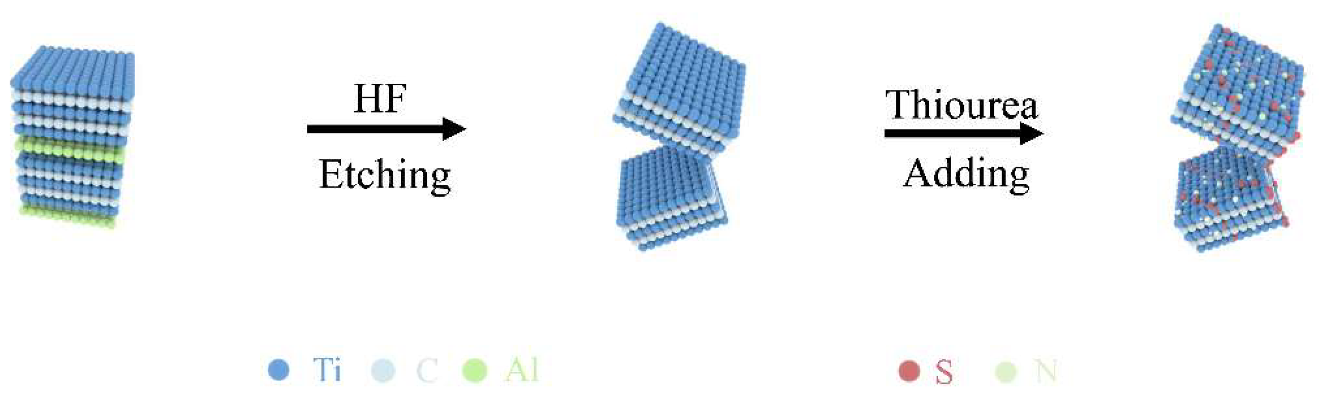
2.2. Preparation of MXene

The Ti3C2 was synthesized by etching with LiF and HCl. The solution was combined with 2 g of LiF and 40 mL of HCl, followed by stirring for 30 min. Subsequently, 2 g of Ti3AlC2 was gradually incorporated into the mixture, followed by stirring at room temperature for 24 h. Finally, the Ti3C2 MXene was obtained after being etched by centrifugation of the combined solution.

2.3. Preparation of Thiourea-Ti3C2

The synthesis of the NS-TC composite was accomplished by pyrolyzing two different types of polymers. A typical experiment consisted of dissolving 0.2 g of Ti3C2 MXene in 100 mL of clean water, stirring the mixture while being protected by nitrogen, and ensuring that it was evenly distributed. Following that, 0.002 g of PEG400 was added, and the mixture was stirred continuously until it was evenly distributed. In order to remove the water, the mixture was freeze-dried. A 0.2 g amount of thiourea was dissolved in ethyl acetate to create a solution that was 10 wt %. The solution was then agitated at room temperature while nitrogen protection was used to eliminate oxygen from the solution. This was performed in order to synthesize NS-TC. After that, 0.2 g of the Ti3C2 MXene product that had been made earlier was added, and the mixture was agitated for a whole night in order to ensure uniform dispersion. After pouring the liquid into the freeze drier, freeze-dry it for up to three days. Finally, in order to generate a stable starting product of the NS-TC composite, the temperature was progressively raised to 500 °C for a period of three hours while the environment was composed of nitrogen.

2.4. Characterization

The phase structure of the obtained samples was tested by X-ray diffraction (XRD) (Rigaku, Rint-2000, Tokyo, Japan). The surface morphology and internal structure were studied using a scanning electron microscope (SEM) (JEOL, JSM-5612LV, Tokyo, Japan) and a transmission electron microscope (TEM) (Titan, G260-300, Prague, Czech Republic). The electron valence of the composite was studied with X-ray photoelectron spectroscopy (XPS) (ESCALAB 250Xi, Thermo Fisher Scientific, Waltham, MA, USA). The composition ratio of the amorphous carbon and graphite carbon was determined using a Raman spectrometer. The amount of carbon in the composite was analyzed by thermogravimetric analysis (DTG-60) at temperatures of 20−800 °C.

2.5. Electrode Preparation

The resultant NS-TC was combined with carbon black (Super C 65, Timcal, Bodio, Switzerland) and PVDF, a binder, to form composite electrodes. The parts were 70:15:15 in ratio. The binder was first dissolved using ultrasonication after being combined with the solvent. Prior to adding the remaining components, the mixture was dispersed for a minimum of 30 m at 6000 rpm using an Ultra Turrax dispersion instrument (IKA, Guangzhou, China). The wet thickness of the slurry may be modified by casting it onto a 16 µm structured copper foil. After being left to dry at ambient temperature for 20 h, the composite was subjected to a vacuum for 3 h at 120 °C. Disks of 9 mm in diameter were made from the electrodes. In a glovebox filled with argon, CR2032 coin-type cells were built with a counter electrode of potassium foil and a separator of glass microfiber filters (Whatman GF/A, Maidstone, UK). A full day before testing, the batteries were inserted. Mixing 0.8 M KPF6 with a 1:1 ratio of ethylene carbonate to diethyl carbonate, v/v makes up the electrolyte.

2.6. Electrochemical Measurements

The LAND-CT3002A measuring machine (LANHE Co., Ltd., Wuhan, China) was used to measure galvanostatic charge and discharge at a voltage range of 0.1 to 3 V and different current rates at room temperature. This study did CV tests at room temperature on a CHI660E electrochemical machine from Chenhua Co., Ltd. in Shanghai, China, with diverse scan rates. A CHI660E electrochemical machine was used to measure the electrochemical impedance spectra over a frequency range of 100 kHz to 10 mHz with an AC fluctuation of 5 mV.

3. Results

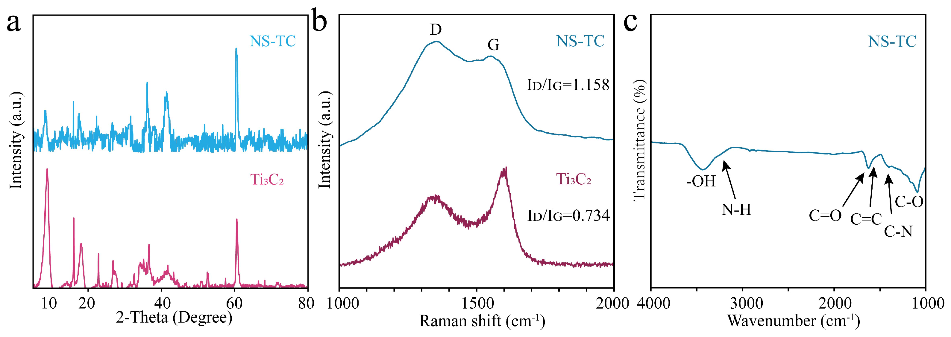
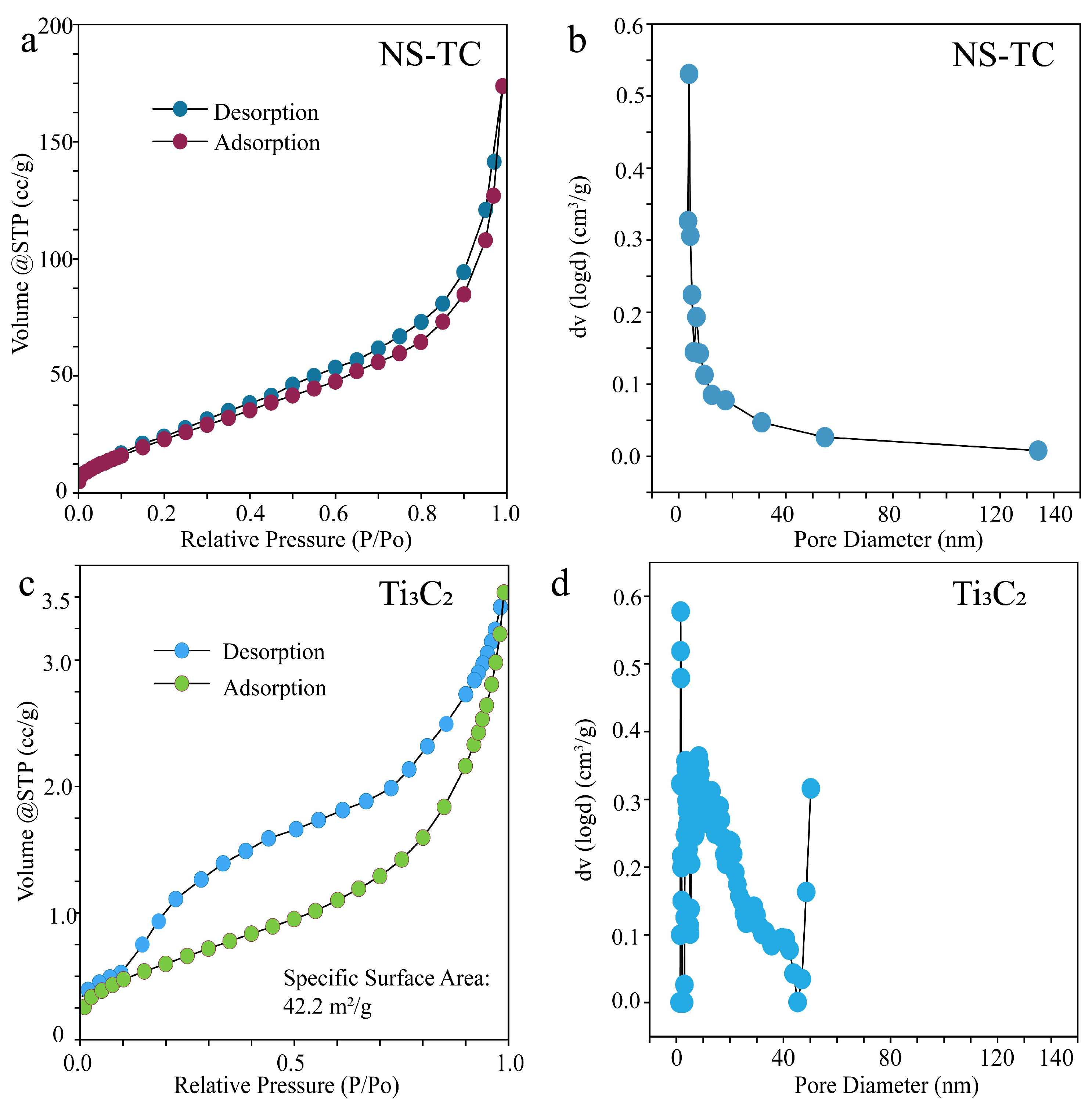
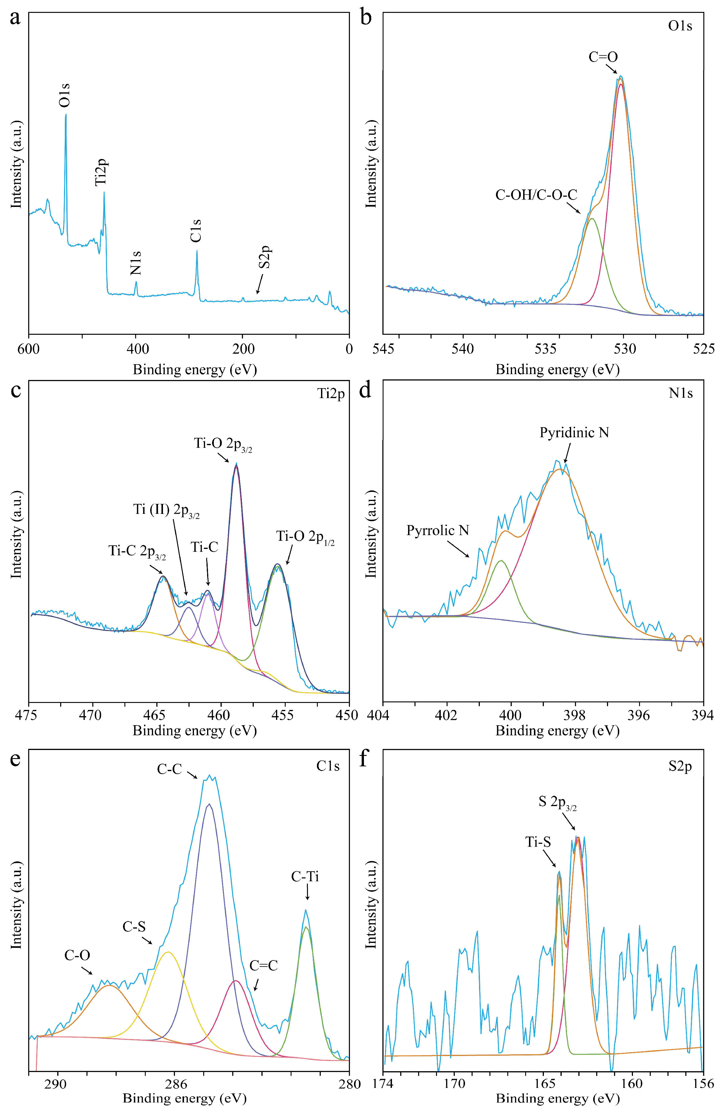
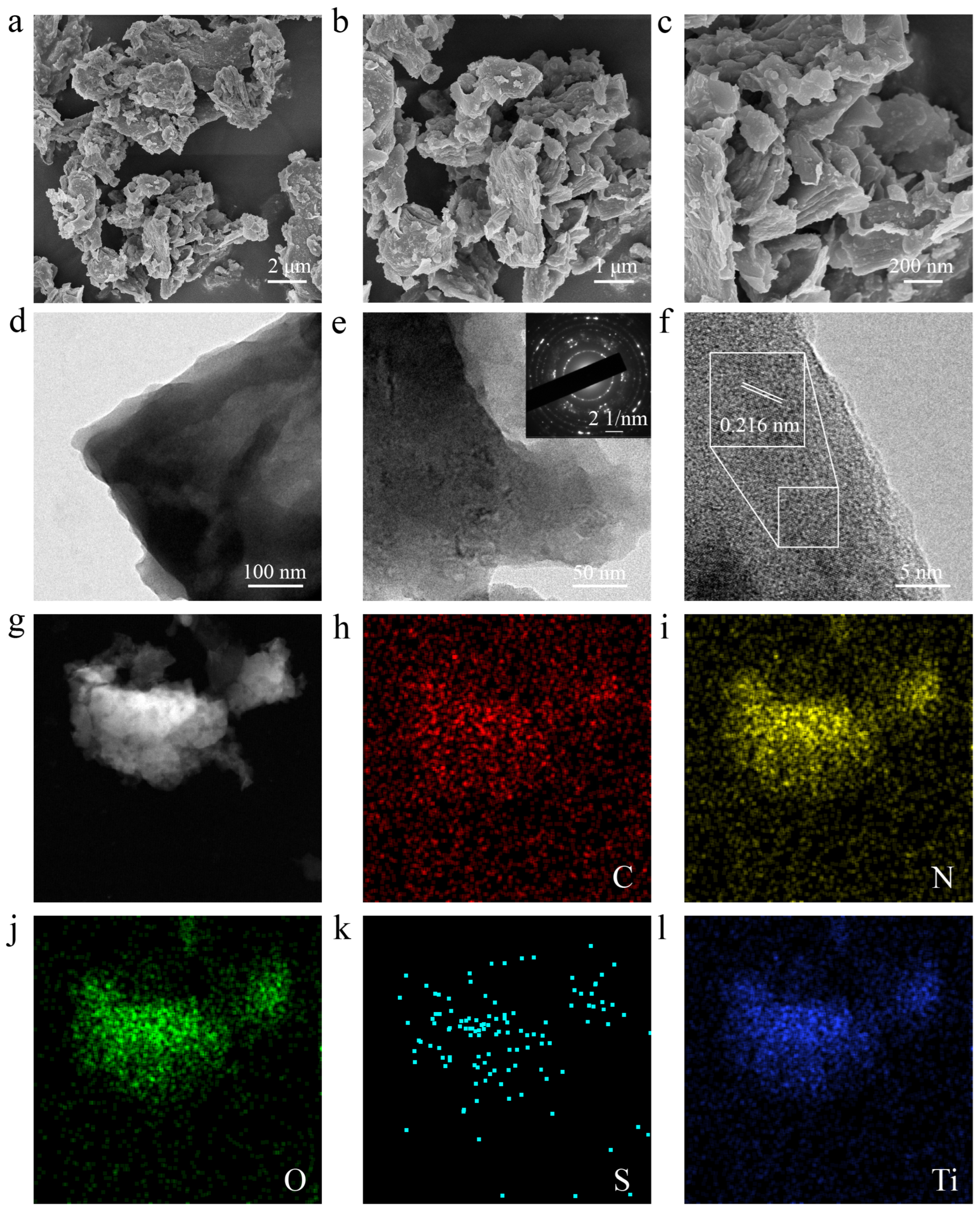
3.1. Structural and Morphology Characterization

To synthesize NS-TC, the process is illustrated in Figure 1. Initially, Ti3C2 is obtained by etching the Al layers from Ti3AlC2 using HF. This is followed by compositing the material with thiourea to produce NS-TC. NS-TC is a material based on the two-dimensional (2D) multilayer structure of MXene, with N and S attached to its surface. The inclusion of N and S introduces supplementary active sites for potassium ions, while their positioning between the MXene layers enhances interlayer spacing, thereby effectively inhibiting MXene restacking. X-ray diffraction (XRD) analysis was performed to examine the crystal structure and properties of the sample.
Figure 2a illustrates the characterization of the crystal structures of Ti3C2 and NS-TC. The XRD pattern of the NS-TC composite resembles that of Ti3C2, exhibiting a shift in the typical (002) peak. The addition of thiourea to MXene results in interlayer reactions, leading to an increase in the interlayer spacing. The larger interlayer spacing is beneficial for the rapid insertion and extraction of K+.
Figure 2b displays the Raman spectra of NS-TC beside the pure Ti3C2 control sample. Raman spectroscopy is used to assess the ratio of graphitic carbon in the samples [40]. In both samples, the peaks that are located at 1348 cm−1 and 1574 cm−1 belong to the D band, which is characterized by disordered carbon, and the G band, which is characterized by graphitic carbon. The intensity ratio of these peaks is represented by the equation ID: IG. The NS-TC control sample has a higher ID: IG value of 1.158 compared to the Ti3C2 control sample’s 0.734. This disparity signifies that NS-TC has a greater quantity of disordered carbon and defects relative to the control sample, whereas the addition of thiourea (as a precursor, introduces N and S) enhances the presence of active sites in NS-TC. Figure 2c illustrates the Fourier transform infrared (FTIR) spectra of the NS-TC composite material. The spectrum indicates the widespread existence of defects and oxygen-containing functional groups in NS-TC by revealing the presence of functional groups such -OH, N-H, C=O, C=C, C-N, and C-O. The flaws and functional groups augment the adsorption of K+ in the sample, hence enhancing its reversible specific capacity.
When it comes to conducting in-depth research on the specific surface area and pore size distribution of materials, the Brunauer–Emmett–Teller (BET) analytical technique is among the most accurate methodologies available. The isotherm of NS-TC displays a type IV isotherm, as can be seen in Figure 3a. This is an indication that the material has hysteresis, and it also suggests that the sample contains a mesoporous structure. As can be seen in Figure S1, the BET-specific surface area is calculated to be 200.09 m2g−1, which is a substantial amount larger than the surface area of Ti3C2 shown in Figure 3c (42.20 m2g−1). Increasing the specific surface area is good because it makes it easier for the electrode material to touch the liquid and gives K+ more places to enter and leave the material, which raises its specific capacity.
Using the Barrett–Joyner–Halenda (BJH) technique, the pore size distribution curve was studied, and the results showed that the pore size was 3.83 nm (while the Ti3C2’s pore size was 2.81 nm shown in Figure 3d). This pore size may be ascribed to the etching of the material by HF, which led to the development of pores. Figure 3b displays the results of this analysis. Additionally, the porous structure of the material contributes to the reduction of the ion diffusion route between the electrodes, which ultimately results in an improvement in the rate performance of the material. In addition, the porous structure of the battery offers ample area to tolerate the volume variations that occur throughout the cycling process, which ultimately results in an improvement in cycle stability.
An X-ray photoelectron spectroscopy (XPS) investigation was carried out in order to obtain a better understanding of the elemental composition and electronic binding energy of NS-TC. The findings of this research are shown in Figure 4. O, Ti, N, C, and S are all shown to be present in the sample by the XPS survey spectrum, which can be seen in Figure 4a. An in-depth analysis of each component yields further information, including the following:
Deconvoluting the high-resolution O 1s spectra (Figure 4b) into two peaks at 531.8 eV and 530.2 eV, which correspond to C-OH/C-O-C and C-O bonds, respectively, is possible as a result of the overlap of two peaks. Ti-C 2p3/2 (464.7 eV), Ti (II) 2p3/2 (462.5 eV), Ti-C (461 eV), Ti-O 2p3/2 (458.8 eV), and Ti-O 2p1/2 (455.5 eV) are the five unique peaks that may be seen in the Ti 2p spectrum, which can be shown in Figure 4c. There are two peaks that correspond to pyrrolic N (400.3 eV) and pyridinic N (398.5 eV) in the N 1s spectrum, which can be seen in Figure 4d. There are three peaks that can be seen in the C 1s spectra (Figure 4e), and they are for the bonds C-O (287.5 eV), C-S (286.2 eV), C-C (284.8 eV), C=C (284.4 eV) and C-Ti (281.7 eV). Figure 4f shows that the S 2p spectra may be deconvoluted into two peaks, one at 164.1 eV and the other at 163 eV. These peaks are assigned to the Ti-S bond and the S 2p3/2 bond, respectively. Thiourea successfully acted as an N-S-sulfur precursor, allowing the incorporation of N and S into Ti3C2 MXene to form the NS-TC composite, as shown by the existence of N 1s and S 2p spectra. Highlighting its distinctive mesoporous structure, varied chemical bonding, and high specific surface area, which indicate promising electrochemical properties, this thorough investigation lays a firm groundwork for comprehending the possible performance of NS-TC in applications involving potassium-ion batteries.
The scanning electron microscopy (SEM) technique was used for the purpose of conducting observations in order to better investigate the overall framework and interior structure of NS-TC. As can be seen in Figure 5a, the sample has a structure that is composed of many layers. When compared to pure Ti3C2 (see Figure S2), NS-TC exhibits thiourea bonded to its surface. This not only helps to maintain the layered structure but also helps to increase the gaps between the accordion-like MXene layers while maintaining the structure.
Figure 5b,c present higher-magnification SEM images of NS-TC, revealing that N and S are coated on the surface of Ti3C2. This is consistent with the finding that was reached earlier, which stated that the incorporation of N and S increases the interlayer spacing of Ti3C2, hence supplying a greater number of active sites for the smooth insertion and extraction of K+. In addition, the N and S coating on the Ti3C2 surface prevents direct interaction between the substance and the electrolyte, thereby protecting the material from oxidation and stabilizing the structure.
Further characterization of the NS-TC microstructure was accomplished by using transmission electron microscopy (TEM) and high-resolution transmission electron microscopy (HRTEM), which stand for high-resolution transmission electron microscopy. Figure 5d shows a low-magnification TEM picture, illustrating the multilayered architecture of NS-TC. Figure 5e shows a high-resolution HRTEM picture that displays the incorporation of N and S on the surface of Ti3C2.
The selected area electron diffraction (SAED) pattern corresponds to the (100) and (110) planes of Ti and C. The lattice spacing shown in Figure 5f is 0.216 nm, corresponding to the (111) crystal plane of Ti3C2. Compared to the 0.203 nm lattice spacing of the Ti3C2 (111) crystal plane (see Figure S3), the increased interplanar spacing in NS-TC indicates that the attachment of N and S have expanded the crystal plane spacing of Ti3C2, consistent with the previous findings.
Furthermore, energy-dispersive X-ray spectroscopy (EDS) maps in Figure 5g–l reveal the elemental composition inside the sample. The even distribution of oxygen (O), titanium (Ti), carbon (C), nitrogen (N), and sulfur (S) across the material indicates that N and S are uniformly attached to the surface of Ti3C2.

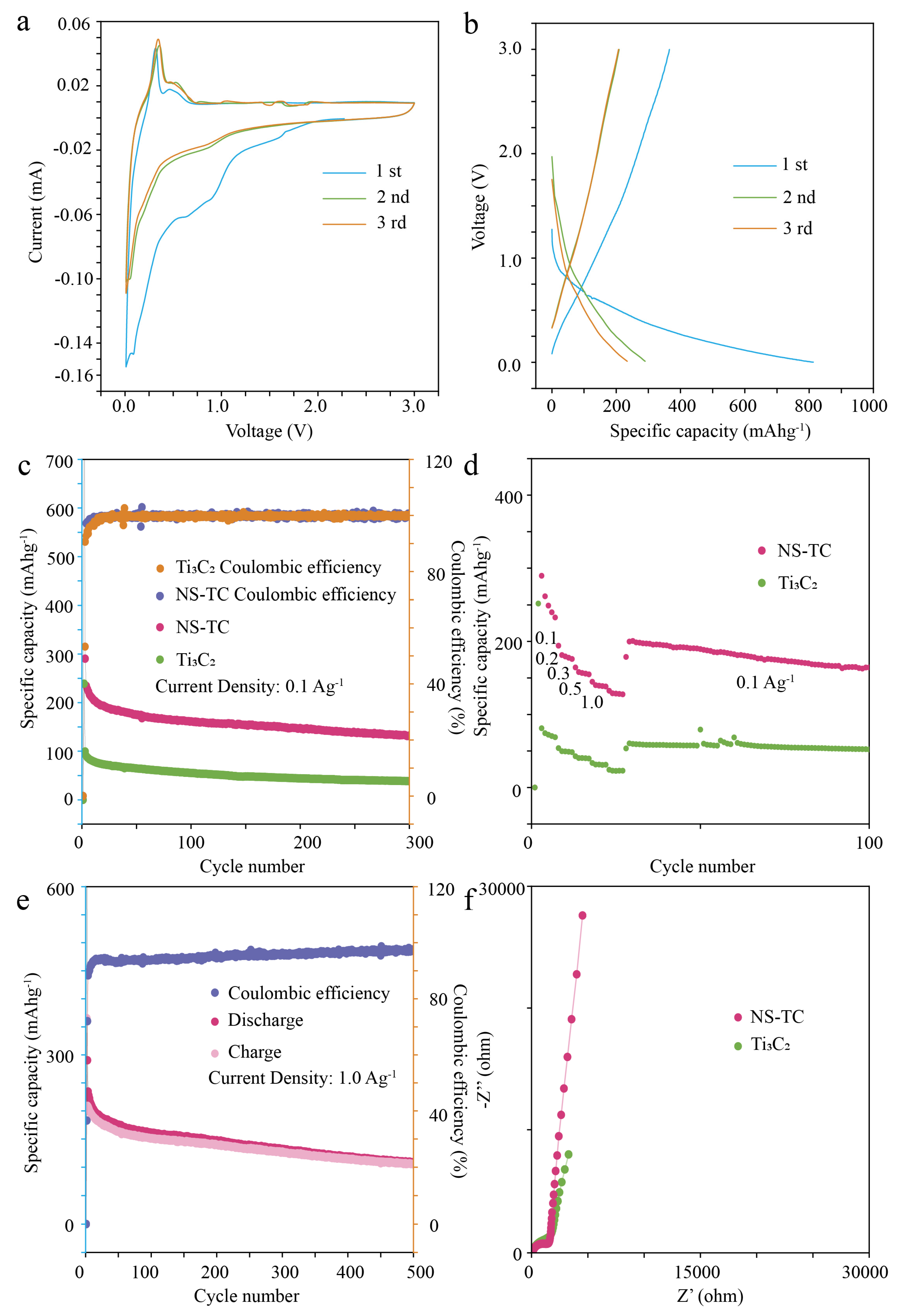
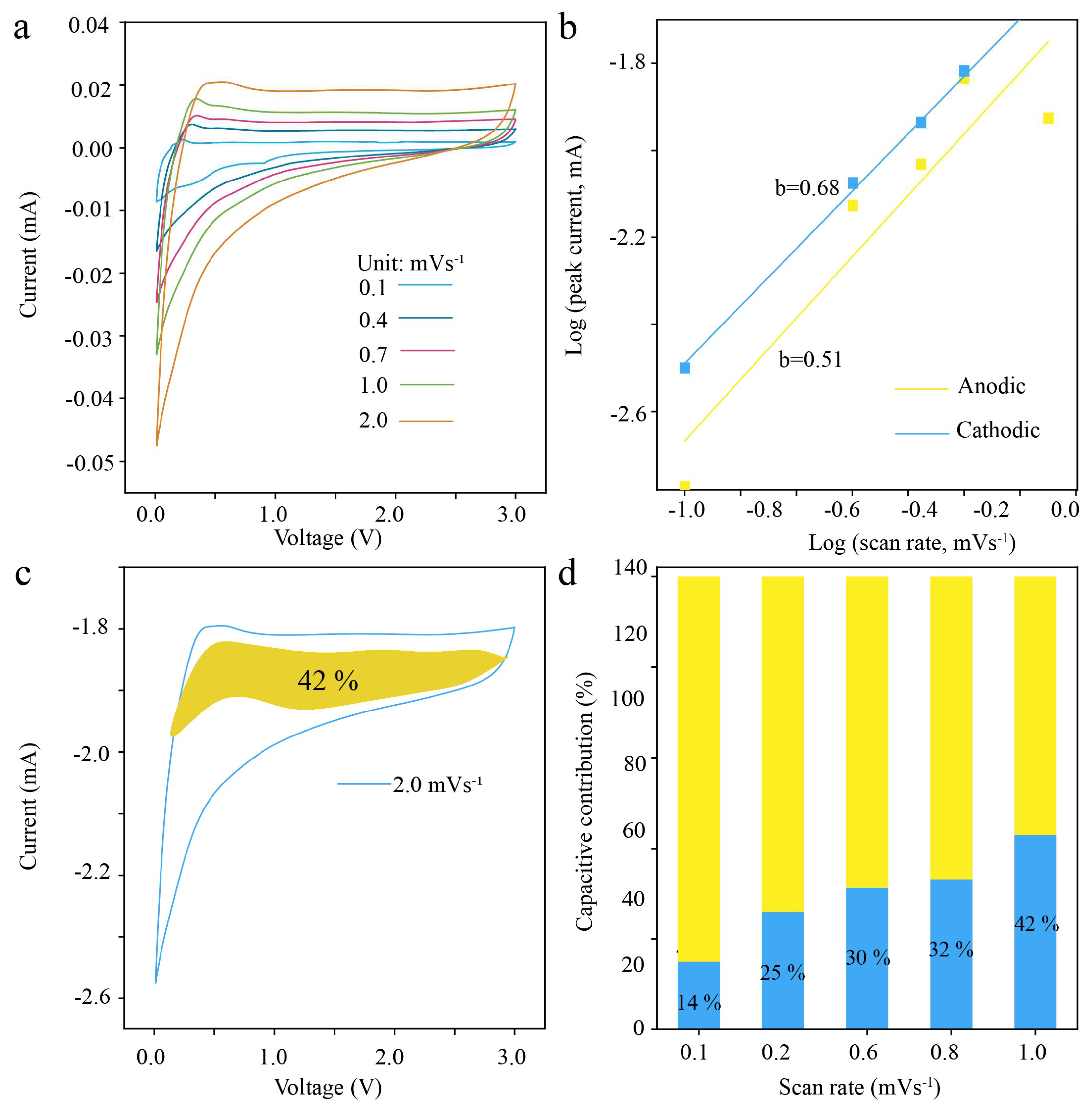
3.2. Electrochemical Performance

Compared to Ti3C2, the NS-TC material benefits from the incorporation of N and S, which enhances the number of active sites and defects while preserving the MXene’s two-dimensional accordion-like structure. This distinctive architecture establishes a robust foundation for NS-TC in making battery anodes. To further assess the performance of potassium storage of NS-TC, cyclic voltammetry (CV) tests were conducted over a voltage range of 0.01 V to 3 V at a scan rate of 0.1 mV/s.
As illustrated in Figure 6a, a prominent reduction peak is observed during the initial reduction reaction, especially in the 0.5–1 V range. Nonetheless, these peaks vanish in subsequent cycles. This behavior can be because of chemical reactions that take place on the surface of the electrode during the first discharge; these reactions cause the electrolyte to be partially consumed and a layer of solid electrolyte interphase (SEI) to be formed [41,42]. The formation of this SEI layer is irreversible and inhibits direct contact between the anode and electrolyte in later charge–discharge cycles, thereby stabilizing the anode material.
Additionally, the notable reduction peak in this range is associated with the partial intercalation of potassium ions between the NS-TC layers and the adsorption of some potassium ions on the NS-TC surface. A strong oxidation peak in the 0–0.3 V range during the anodic scan further indicates the release of potassium ions from the multilayer structure of the material. Over subsequent cycles, the overlapping of the redox peak curves demonstrates that NS-TC possesses excellent capabilities for potassium ion intercalation and extraction, along with good cyclic reversibility. For comparison, the CV curves of Ti3C2 before and after the composite process are presented in Figure S4, showing a similar shape to that of NS-TC.
The image demonstrates a significant decrease peak in the 0.5 V region, confirming the successful intercalation of potassium ions into the multilayer structure of Ti3C2. The pronounced peak at 0.1 V signifies the alloying process between potassium and carbon. The anodic scan reveals a pronounced oxidation peak within the 0–0.5 V range, signifying the extraction of potassium ions from the porous multilayer structure.
Throughout the charging process, several anodic peaks emerge between 0.5 and 1.5 V, ascribed to the extraction of K+ ions and the reversible conversion reaction associated with phosphorus. The reversible transformation may be articulated by the following equation:
S8 + 16K+ + 16e ⟷ 8K2S
Ti3C2 + xK+ + xe ⟷ KxTi3C2 (0.1 V)
The CV behavior indicates that the NS-TC experiences substantial surface responses during the first cycle, possibly establishing the foundation for the electrode’s steady performance in later cycles. The preliminary “activation” phase is characteristic of several battery electrode materials and is crucial for attaining steady cycle performance.
The CV data provide significant insights into the preliminary electrochemical processes taking place in the NS-TC electrode. Additional examination of the next cycles, particularly in relation to the cyclic voltammetry characteristics of unaltered Ti3C2, could provide a deeper understanding of how N and S modification influences the potassium storage mechanism and enhances the overall performance of the electrode.
Figure 6b depicts the charge–discharge curves of the NS-TC composite across the first three cycles, indicating that the voltage platforms nearly correspond with the redox peaks seen in the CV curves. NS-TC demonstrates an impressive initial discharge capacity of 808.1 mAhg−1 and a charging capacity of 391.5 mAhg−1 at a current density of 100 mAg−1. Furthermore, starting from the second cycle, the curves exhibit excellent overlap, reinforcing the outstanding electrochemical performance of NS-TC. In contrast, Ti3C2 exhibits markedly reduced initial discharge and charge capacities of just 239 mAhg−1 and 90 mAhg−1, respectively, at the same current density (refer to Figure S5). The charge–discharge curves of Ti3C2 exhibit inadequate overlap during the early three cycles, underscoring the significant improvement in electrochemical performance attained with the integration of NS-TC.
Figure 6c shows that the NS-TC electrode’s cycling performance reaches 141 mAhg−1 after 300 cycles at 100 mAg−1. Even after several cycles, the composite material maintains its coulombic efficiency of over 98%. At the same current density and after 300 cycles, the Ti3C2 composite electrode has a reversible capacity of 38.5 mAhg−1 but has a poor coulombic efficiency (after 50 cycles, coulombic efficiency reached 98%). The difference may be explained by the fact that Ti3C2 has N and S on its surface, which creates several active sites for the adsorption of potassium ions. To verify the repeatability of the superior electrochemical performance of NS-TC, Figure S6 shows the cycling curves of three different batteries at a current density of 100 mAg−1. It can be seen that the three different batteries basically maintain consistency in terms of cycling performance, indicating that NS-TC has excellent repeatability.
The rate performance of NS-TC is shown in Figure 6d. Rate capabilities are attained by the material in cycles 3, 8, 13, 18, and 23 are about 197.2, 180.4, 169.3, 147.6, and 153.3 mAhg−1 at current densities of 100, 200, 300, 500, and 1000 mA g−1, respectively. When the current density is restored to 100 mAg−1, the capacity rises to 205.2 mAhg−1 and remains stable. In contrast, Ti3C2 exhibits capacities of 60.0, 45.0, 38.0, 30.0, and 22.0 mAhg−1 during the same cycles, with a capacity of only 50 mAhg−1 when returning to 100 mAg−1. Clearly, the increased interlayer spacing and improved rate performance of NS-TC are both caused by the presence of N and S on the surface of Ti3C2, the smooth ingress and the egress of potassium ions. At the same time, the presence of Ti-S bonds enhances the conductivity of NS-TC, thereby improving its rate performance. Figure 6e shows how well NS-TC performs over a lengthy period of time. With a coulombic efficiency higher than 99%, NS-TC maintains a consistent capacity of 128.5 mAhg−1 even after 500 cycles at 500 mAg−1. Electrolyte breakdown, side reactions, and the creation of an SEI layer all contribute to a drop in initial capacity during the first cycle of long-term cycling. Cycling after SEI layer creation, however, activates the active material and stabilizes capacity. Because it generates a stable structure, inhibits self-aggregation, and resists oxidation, the N and S coating on the surface of Ti3C2 and the presence of Ti-S bond are responsible for the long-term cycle stability. The N and S composite provide abundant defects, expand the interlayer spacing, enhance the material’s viscoelasticity, absorb K+ ions to improve reversible capacity, and simultaneously suppress the oxidation of Ti3C2, enhancing both rate capacity and cycling stability.
To further analyze the kinetics of the NS-TC electrode, electrochemical impedance spectroscopy (EIS) was conducted. The EIS (Figure 6f) displays a semicircle in the mid-low frequency region and a linear response in the high-frequency band, signifying charge transfer resistance and ionic diffusion rate, respectively. The high-frequency process of NS-TC terminates at 1300 Ω, while that of Ti3C2 terminates at 1497 Ω, indicating that NS-TC has better electron transfer. The improved electron transport is ascribed to the presence of Ti-S bonds, which enhances the conductivity of NS-TC, and also signifies an improvement in the electron transfer rate of NS-TC.
To verify the influence of different concentrations of NS on the electrochemical properties of the material, materials were synthesized with different concentrations of thiourea added. Subsequently, cyclic tests were carried out on them at a current density of 100 mAg−1. The results are shown in Figure S7. When the doping amount of thiourea is 0.2 g, the material exhibits the best electrochemical performance.
It is well known that structural changes in electrodes can impact the electrochemical performance of batteries after prolonged cycling. To investigate this effect, TEM and SEM were used to dismantle and examine batteries that had been cycled for an extended period of time. Figure 7a–c show scanning electron micrographs of NS-TC. It should be noted that even after 1000 cycles at a current density of 100 mAg−1, the NS-TC electrode’s structure shows no signs of material pulverization or aggregation, and it still looks complete and smooth.
Despite several deep discharge and charge cycles, the structure of the NS-TC electrode stays the same, as seen by TEM pictures (Figure 7d–f), with the composite of N and S still present on the surface of Ti3C2. Figures of the NS-TC electrode taken with an energy-dispersive spectrophotometer (EDS) are shown in Figure 7g–j. These photos indicate that the elements are distributed uniformly throughout the sample. All of these findings highlight how stable the NS-TC electrode is over many cycles.
The electrochemical kinetics of potassium ion storage in the NS-TC electrode for potassium-ion batteries was studied using CV. Figure 8a shows the results of the experiment, which included obtaining CV curves within a potential range of 0.01 to 3 V at scan speeds of 0.1 to 1.0 mV/s. The NS-TC electrode shows strong reversibility; the oxidation–reduction peaks show small alterations at different scan speeds, but their general geometries stay the same. The region contained by the CV curves grows at increasing scan rates, demonstrating the existence of pseudocapacitive behavior in NS-TC. This finding is very noteworthy.
This study used the following equation to go further into this behavior analysis:
I = a v b
in which a constant, I stands for current of the oxidation/reduction peak., and a is a constant, b is the fitting parameter (which may take values between 0 and 1), and v is scan rate. Behavior that is regulated by diffusion is indicated by a b value between 0 and 0.5, while pseudocapacitive behavior is suggested by a value between 0.5 and 1. The existence of pseudocapacitive behavior in NS-TC is further supported by the fitted values, which, as shown in Figure 8b, provide a cathode b value of 0.91 and an anode b value of 0.86.
At certain scan rates, the following equation may be used to quantitatively evaluate the contribution of pseudocapacitance:
i v = k 1 v + k 2 v 1 / 2
The current at a constant voltage v is denoted by i(v) in this equation. The current at a fixed voltage is represented by i(v) in this equation, where v is the scan rate, and k1 and k2 are constants. Figure 8c shows that the NS-TC composite electrode’s pseudocapacitive contribution was 95.2% at a scan rate of 1.0 mV/s.
Figure 8d displays further pseudocapacitive contribution rate analysis at different scan speeds. An interesting observation is that the percentage of pseudocapacitive contribution grows with increasing scan rate, going from 48.8% at 0.1 mV/s to 95.2% at 1.0 mV/s. This dramatic improvement in pseudocapacitive behavior is a result of an increase in the surface area of the electrode material’s ability to absorb potassium ions, which allows for faster adsorption and desorption. This allows the NS-TC electrode to reach a greater rate capacity.
Compared with the pseudocapacitance-related data of Ti3C2 in Figure S8, NS-TC has a higher pseudocapacitance contribution rate. This indicates that NS-TC has a higher efficiency in the intercalation and deintercalation of potassium ions than TC, suggesting that the NS-TC electrode has a higher rate capacity when used as a negative electrode material.
The fantastic rate capability and cycle stability of the NS-TC electrode in potassium-ion batteries, as well as other high-performance properties, may be further understood with the help of this electrochemical kinetics study.

4. Conclusions

Using a freeze-drying pyrolysis process, the NS-TC composite material was successfully produced. Thiourea, as a precursor, effectively attaches N and S to the surface of Ti3C2 MXene. This method increases the interlayer spacing during the reaction, alleviates the self-aggregation of Ti3C2, and improves the material’s viscoelasticity. At the same time, the incorporation of N and S not only enhances the potassium storage capacity of NS-TC but also increases the number of edge sites on the Ti3C2 surface. Furthermore, it introduces a significant number of surface functional groups and defects, thereby increasing the material’s specific surface area. These structural improvements significantly enhance the potassium ion adsorption capability of NS-TC.
The experimental results highlighted the impressive electrochemical performance of NS-TC. At a current density of 100 mAg−1, it maintained a reversible capacity of 141 mAg−1, demonstrating good stability even after 300 cycles. Moreover, NS-TC retained a capacity of 128.5 mAhg−1 following 500 cycles at a heightened current density of 500 mAg−1. The coulombic efficiency is often around 99%, signifying high electrochemical reversibility. NS-TC signifies a significant advancement for Ti3C2 MXene in energy storage applications, owing to its unique structural attributes and improved active sites. This study promotes the advancement and improvement of MXene-based materials for next-generation battery technologies.

Supplementary Materials

The following supporting information can be downloaded at: https://www.mdpi.com/article/10.3390/cryst15040353/s1, Figure S1: (a) Adsorption–desorption isotherms of Ti3C2 (b) Pore size distribution profiles of Ti3C2; Figure S2. SEM image of Ti3C2.; Figure S3. TEM image of Ti3C2; Figure S4. The first 3 cycles CV curves of Ti3C2; Figure S5. The constant current charge-discharge curves for the first three cycles of Ti3C2; Figure S6. At 100 mAg−1, the 3 different cells of NS-TC cycling performance; Figure S7. At 100 mAg−1, the different NS concentration gradients cycling performance; Figure S8. (a) CV curves collected at scan speeds ranging from 0.1 to 1.0 mVs−1 of the Ti3C2 composite material (b) The values of b that are derived by comparing the logarithm of scan rates with the logarithm of peak currents (c) At a scan rate of 1.0 mVs−1, the Ti3C2 composite material’s pseu-docapacitive contribution (d) At different scan speeds, the Ti3C2 composite material’s pseudo-capacitative contributions.

Author Contributions

Methodology, J.P. and Z.F.; Resources, K.W. (Kaidan Wu) and K.W. (Kunhua Wen); Software, D.X.; Supervision, M.H.; Writing—original draft, J.Z.; Writing—review and editing, Y.F. All authors have read and agreed to the published version of the manuscript.

Funding

This work was supported by the State Key Laboratory of Precision Electronic Manufacturing Technology and Equipment, Guangdong University of Technology, China.

Data Availability Statement

No new data were created or analyzed in this study.

Conflicts of Interest

Authors Yefeng Feng and Miao He were employed by the company Guangzhou Qingbei Intelligent Technology Co., Ltd. The remaining authors declare that the research was conducted in the absence of any commercial or financial relationships that could be construed as a potential conflict of interest.

Abbreviations

The following abbreviations are used in this manuscript:
NS-TCNitrogen–sulfur–Ti3C2
NS-MXeneNS-MXene
PIBsPotassium-ion batteries
PIBPotassium-ion battery
2DTwo-dimensional
XRDX-ray diffraction
FTIRFourier transform infrared
BETBrunauer–Emmett–Teller
BJHBarrett–Joyner–Halenda
XPSX-ray photoelectron spectroscopy
SEMScanning electron microscopy
TEMTransmission electron microscopy
HRTEMHigh-resolution transmission electron microscopy
SAEDSelected area electron diffraction
EDSEnergy-dispersive X-ray spectroscopy
AFMAtomic force microscopy
CVCyclic voltammetry
SEISolid electrolyte interphase
EISElectrochemical impedance spectroscopy

References

  1. Li, M.; Du, Z.; Khaleel, M.A.; Belharouak, I. Materials and engineering endeavors towards practical sodium-ion batteries. Energy Storage Mater. 2020, 25, 520–536. [Google Scholar] [CrossRef]
  2. Fang, Y.; Xiao, L.; Chen, Z.; Ai, X.; Cao, Y.; Yang, H. Recent Advances in Sodium-Ion Battery Materials. Electrochem. Energy Rev. 2018, 1, 294–323. [Google Scholar] [CrossRef]
  3. Pan, H.; Hu, Y.-S.; Chen, L. Room-temperature stationary sodium-ion batteries for large-scale electric energy storage. Energy Environ. Sci. 2013, 6, 2338–2360. [Google Scholar] [CrossRef]
  4. You, Y.; Manthiram, A. Progress in High-Voltage Cathode Materials for Rechargeable Sodium-Ion Batteries. Adv. Energy Mater. 2017, 8, 1701785. [Google Scholar] [CrossRef]
  5. Zhang, H.; Gao, Y.; Liu, X.; Zhou, L.; Li, J.; Xiao, Y.; Peng, J.; Wang, J.; Chou, S.L. Long-Cycle-Life Cathode Materials for Sodium-Ion Batteries toward Large-Scale Energy Storage Systems. Adv. Energy Mater. 2023, 13, 2300149. [Google Scholar] [CrossRef]
  6. Bai, X.; Wu, N.; Yu, G.; Li, T. Recent Advances in Anode Materials for Sodium-Ion Batteries. Inorganics 2023, 11, 289. [Google Scholar] [CrossRef]
  7. Wen, X.; Zhu, X.; Tang, X.; Wu, Y.; Wang, Y.; Man, Z.; Qi, W.; Wang, J.; Lv, Z. A revolutionary design concept: Full-sealed lithium-oxygen batteries. Nano Energy 2024, 123, 109405. [Google Scholar] [CrossRef]
  8. Miyakawa, S.; Goto, M.; Ono, M.; Saito, T.; Yamaguchi, S.; Matsuda, S. Metal-Coated Polymer Fiber Mesh as an Ultralightweight Gas-Diffusible Current Collector for High-Energy-Density Rechargeable Lithium–Oxygen Batteries. ACS Appl. Energy Mater. 2023, 6, 1906–1912. [Google Scholar] [CrossRef]
  9. Jiang, K.; Liu, X.; Gao, Y.; Yi, X.; Lou, G.; Wen, Z. Study on evolution process and electrochemical behavior of porous cathode in discharge process of the solid-state lithium-oxygen battery. J. Energy Storage 2023, 74, 109315. [Google Scholar] [CrossRef]
  10. Krammer, M.; Schmid, A.; Kubicek, M.; Fleig, J. Utilizing oxygen gas storage in rechargeable oxygen ion batteries. J. Power Sources 2023, 577, 233167. [Google Scholar] [CrossRef]
  11. Liu, J.; Shi, R.; Lang, X.; Wang, T.; Qu, T.; Li, L.; Yao, C.; Lai, Q.; Cai, K. Construction of a novel high electrochemical performance nanosheet Co3O4@Fe2O3 bifunctional catalytic material for lithium-oxygen batteries. Electrochim. Acta 2024, 474, 143569. [Google Scholar] [CrossRef]
  12. Fu, Z.; Wang, S.; Yu, H.; Nie, M.; Feng, X.; Zuo, X.; Fu, L.; Liu, D.; Zhang, Y. CeO2 Supported on Reduced Graphene Oxide as Li-O2 Battery Cathode. Chem. Res. Chin. Univ. 2023, 39, 636–641. [Google Scholar] [CrossRef]
  13. Wang, B.; Liu, C.; Yang, L.; Wu, Q.; Wang, X.; Hu, Z. Defect-induced deposition of manganese oxides on hierarchical carbon nanocages for high-performance lithium-oxygen batteries. Nano Res. 2022, 15, 4132–4136. [Google Scholar] [CrossRef]
  14. Naguib, M.; Mochalin, V.N.; Barsoum, M.W.; Gogotsi, Y. Two-Dimensional Materials: 25th Anniversary Article: MXenes: A New Family of Two-Dimensional Materials. Adv. Mater. 2014, 26, 982. [Google Scholar] [CrossRef]
  15. Pang, J.; Mendes, R.G.; Bachmatiuk, A.; Zhao, L.; Ta, H.Q.; Gemming, T.; Liu, H.; Liu, Z.; Rummeli, M.H. Applications of 2D MXenes in energy conversion and storage systems. Chem. Soc. Rev. 2019, 48, 72–133. [Google Scholar] [CrossRef]
  16. Anasori, B.; Lukatskaya, M.R.; Gogotsi, Y. 2D metal carbides and nitrides (MXenes) for energy storage. In MXenes; Jenny Stanford Publishing: Singapore, 2023; pp. 677–722. [Google Scholar]
  17. Alli, Y.A.; Bamisaye, A.; Nancy, P.; Zachariah, S.M.; Oladoye, P.O.; Bankole, O.M.; Akamo, D.O.; Chkirida, S.; Anuar, H.; Thomas, S. MXene composites: Properties, synthesis and its emerging application in rechargeable batteries. J. Energy Storage 2024, 77, 109954. [Google Scholar] [CrossRef]
  18. Cao, J.-M.; Zatovsky, I.V.; Gu, Z.-Y.; Yang, J.-L.; Zhao, X.-X.; Guo, J.-Z.; Xu, H.; Wu, X.-L. Two-dimensional MXene with multidimensional carbonaceous matrix: A platform for general-purpose functional materials. Prog. Mater. Sci. 2023, 135, 101105. [Google Scholar] [CrossRef]
  19. Anasori, B.; Gogotsi, Y. MXenes: Trends, growth, and future directions. Graphene 2D Mater. 2022, 7, 75–79. [Google Scholar] [CrossRef]
  20. Meng, W.; Liu, X.; Song, H.; Xie, Y.; Shi, X.; Dargusch, M.; Chen, Z.-G.; Tang, Z.; Lu, S. Advances and challenges in 2D MXenes: From structures to energy storage and conversions. Nano Today 2021, 40, 101273. [Google Scholar] [CrossRef]
  21. Mashtalir, O.; Lukatskaya, M.R.; Zhao, M.-Q.; Barsoum, M.W.; Gogotsi, Y. Amine-assisted delamination of Nb2C MXene for Li-ion energy storage devices. In MXenes; Jenny Stanford Publishing: Singapore, 2023; pp. 401–414. [Google Scholar]
  22. Naguib, M.; Mashtalir, O.; Carle, J.; Presser, V.; Lu, J.; Hultman, L.; Gogotsi, Y.; Barsoum, M.W. Two-dimensional transition metal carbides. ACS Nano 2012, 6, 1322–1331. [Google Scholar] [CrossRef]
  23. Anasori, B.; Gogotsi, Û.G. 2D Metal Carbides and Nitrides (MXenes); Springer: Berlin/Heidelberg, Germany, 2019; Volume 2549. [Google Scholar]
  24. VahidMohammadi, A.; Rosen, J.; Gogotsi, Y. The world of two-dimensional carbides and nitrides (MXenes). Science 2021, 372, eabf1581. [Google Scholar] [CrossRef] [PubMed]
  25. Zhao, Q.; Zhu, Q.; Miao, J.; Zhang, P.; Wan, P.; He, L.; Xu, B. Flexible 3D porous MXene foam for high-performance lithium-ion batteries. Small 2019, 15, 1904293. [Google Scholar] [CrossRef] [PubMed]
  26. Hussain, I.; Lamiel, C.; Javed, M.S.; Ahmad, M.; Sahoo, S.; Chen, X.; Qin, N.; Iqbal, S.; Gu, S.; Li, Y. MXene-based heterostructures: Current trend and development in electrochemical energy storage devices. Prog. Energy Combust. Sci. 2023, 97, 101097. [Google Scholar] [CrossRef]
  27. Bashir, T.; Zhou, S.; Yang, S.; Ismail, S.A.; Ali, T.; Wang, H.; Zhao, J.; Gao, L. Progress in 3D-MXene electrodes for lithium/sodium/potassium/magnesium/zinc/aluminum-ion batteries. Electrochem. Energy Rev. 2023, 6, 5. [Google Scholar] [CrossRef]
  28. Huang, W.; Ma, Z.; Zhong, L.; Luo, K.; Li, W.; Zhong, S.; Yan, D. Efficient Self-Assembly Preparation of 3D Carbon-Supported Ti3C2Tx Hollow Spheres for High-Performance Potassium Ion Batteries. Small 2024, 20, 2304690. [Google Scholar] [CrossRef]
  29. Shi, H.; Dong, Y.; Zheng, S.; Dong, C.; Wu, Z.-S. Three dimensional Ti3C2 MXene nanoribbon frameworks with uniform potassiophilic sites for the dendrite-free potassium metal anodes. Nanoscale Adv. 2020, 2, 4212–4219. [Google Scholar] [CrossRef]
  30. Bärmann, P.; Haneke, L.; Wrogemann, J.M.; Winter, M.; Guillon, O.; Placke, T.; Gonzalez-Julian, J. Scalable synthesis of MAX phase precursors toward titanium-based MXenes for lithium-ion batteries. ACS Appl. Mater. Interfaces 2021, 13, 26074–26083. [Google Scholar] [CrossRef] [PubMed]
  31. Nasrin, K.; Sudharshan, V.; Subramani, K.; Sathish, M. Insights into 2D/2D MXene heterostructures for improved synergy in structure toward next-generation supercapacitors: A review. Adv. Funct. Mater. 2022, 32, 2110267. [Google Scholar] [CrossRef]
  32. Pei, Y.; Zhang, X.; Hui, Z.; Zhou, J.; Huang, X.; Sun, G.; Huang, W. Ti3C2TX MXene for sensing applications: Recent progress, design principles, and future perspectives. ACS Nano 2021, 15, 3996–4017. [Google Scholar] [CrossRef]
  33. Kumar, J.A.; Prakash, P.; Krithiga, T.; Amarnath, D.J.; Premkumar, J.; Rajamohan, N.; Vasseghian, Y.; Saravanan, P.; Rajasimman, M. Methods of synthesis, characteristics, and environmental applications of MXene: A comprehensive review. Chemosphere 2022, 286, 131607. [Google Scholar] [CrossRef]
  34. Oh, H.G.; Yang, S.H.; Kang, Y.C.; Park, S.-K. N-doped carbon-coated CoSe2 nanocrystals anchored on two-dimensional MXene nanosheets for efficient electrochemical sodium- and potassium-ion storage. Int. J. Energy Res. 2021, 45, 17738–17748. [Google Scholar] [CrossRef]
  35. Lamiel, C.; Hussain, I.; Warner, J.H.; Zhang, K. Beyond Ti-based MXenes: A review of emerging non-Ti based metal-MXene structure, properties, and applications. Mater. Today 2023, 63, 313–338. [Google Scholar] [CrossRef]
  36. Song, P.; Liu, B.; Qiu, H.; Shi, X.; Cao, D.; Gu, J. MXenes for polymer matrix electromagnetic interference shielding composites: A review. Compos. Commun. 2021, 24, 100653. [Google Scholar] [CrossRef]
  37. Liu, H.; Wu, Q.; Guan, X.; Liu, M.; Wang, F.; Li, R.; Xu, J. Ionically conductive self-healing polymer binders with poly (ether-thioureas) segments for high-performance silicon anodes in lithium-ion batteries. ACS Appl. Energy Mater. 2022, 5, 4934–4944. [Google Scholar] [CrossRef]
  38. Xiong, P.; Yin, H.; Chen, Z.; Zhao, C.; Yang, J.; Huang, S.; Xu, Y. Thiourea-based polyimide/RGO composite cathode: A comprehensive study of storage mechanism with alkali metal ions. Sci. China Mater. 2020, 63, 1929–1938. [Google Scholar] [CrossRef]
  39. Feng, J.; Liu, W.; Shi, C.; Zhang, C.; Zhao, X.; Wang, T.; Chen, S.; Li, Q.; Song, J. Enabling fast diffusion/conversion kinetics by thiourea-induced wrinkled N, S co-doped functional MXene for lithium-sulfur battery. Energy Storage Mater. 2024, 67, 103328. [Google Scholar] [CrossRef]
  40. Boota, M.; Anasori, B.; Voigt, C.; Zhao, M.-Q.; Barsoum, M.W.; Gogotsi, Y. Pseudocapacitive electrodes produced by oxidant-free polymerization of pyrrole between the layers of 2D titanium carbide (MXene). Adv. Mater. 2016, 28, 1517–1522. [Google Scholar] [CrossRef]
  41. Tao, M.; Du, G.; Zhang, Y.; Gao, W.; Liu, D.; Luo, Y.; Jiang, J.; Bao, S.; Xu, M. TiOxNy nanoparticles/C composites derived from MXene as anode material for potassium-ion batteries. Chem. Eng. J. 2019, 369, 828–833. [Google Scholar] [CrossRef]
  42. Dong, Y.; Wu, Z.-S.; Zheng, S.; Wang, X.; Qin, J.; Wang, S.; Shi, X.; Bao, X. Ti3C2 MXene-Derived Sodium/Potassium Titanate Nanoribbons for High-Performance Sodium/Potassium Ion Batteries with Enhanced Capacities. ACS Nano 2017, 11, 4792–4800. [Google Scholar] [CrossRef]
Figure 1. Schematic illustration of the NS-TC composite.
Crystals 15 00353 g001
Figure 2. The XRD pattern of NS-TC is shown in (a). The Raman spectra of Ti3C2 MXene and porous NS-TC composite material are shown in (b,c) shows the FTIR spectra on the NS-TC.
Crystals 15 00353 g002
Figure 3. NS-TC nitrogen adsorption−desorption isotherms are shown in (a). Pore size distribution profiles of NS-TC are presented in (b). Ti3C2 nitrogen adsorption−desorption isotherms are shown in (c). Pore size distribution profiles of Ti3C2 are presented in (d).
Crystals 15 00353 g003
Figure 4. NS-TC’s XPS spectrum is shown in (a). The high-resolution XPS of O 1s is shown in (b). The high-resolution XPS of Ti 2p is shown in (c). The high-resolution XPS of N 1s is shown in (d). The high-resolution XPS of C 1s is shown in (e). The high-resolution XPS of S 2p is shown in (f).
Crystals 15 00353 g004
Figure 5. NS-TC SEM picture is shown in (a). The picture of NS-TC captured using a high-resolution scanning electron microscope (1 θm) is shown in (b). ESEM picture of NS-TC with a high resolution of 200 nm is shown in (c). NS-TC TEM image is shown in (d). NS-TC magnified TEM picture is shown in (e). (f) High-resolution TEM picture and lattice spacing of NS-TC. The transmission electron micrograph of NS-TC with a high resolution is shown in (i). Images of NS-TC’s elemental mapping provided by EDS are shown in (gl).
Crystals 15 00353 g005
Figure 6. The curves representing CV throughout the first three NS-TC cycles are shown in (a). The NS-TC charge–discharge curves for the first three cycles with a constant current are shown in (b). At 100 mAg−1, the NS-TC and Ti3C2 cycling performance is evaluated in (c) and NS-TC’s rate performance curve is shown in (d). At 500 mAg−1, the NS-TC long-term cycling performance curve is shown in (e). The Nyquist charts of NS-TC and Ti3C2 electrodes are shown in (f).
Crystals 15 00353 g006
Figure 7. SEM pictures of NS-TC after extensive cycling (a). High-resolution SEM picture (1 μm) of NS-TC after extensive cycling (b). High-resolution SEM (200 nm) picture of NS-TC after extended cycling (c). TEM picture of NS-TC after extended cycles (d). Enlarged TEM picture of NS-TC after extended cycles (e). High-resolution transmission electron microscopy picture of NS-TC after extensive cycling (f). EDS elemental mapping photos of NS-TC after extensive cycles are shown in (gl).
Crystals 15 00353 g007
Figure 8. CV curves collected at scan speeds ranging from 0.1 to 1.0 mVs-1 of the NS-TC composite material are shown in (a). The values of b that are derived by comparing the logarithm of scan rates with the logarithm of peak currents (b). At a scan rate of 1.0 mVs-1, the NS-TC composite material’s pseudocapacitive contribution is shown in (c). (d) At different scan speeds, the NS-TC composite material’s pseudocapacitive contributions are examined.
Crystals 15 00353 g008
Disclaimer/Publisher’s Note: The statements, opinions and data contained in all publications are solely those of the individual author(s) and contributor(s) and not of MDPI and/or the editor(s). MDPI and/or the editor(s) disclaim responsibility for any injury to people or property resulting from any ideas, methods, instructions or products referred to in the content.

