

Effect of Solid Solution Treatment Routes on the Microstructure Configuration of a Third-Generation Ni-Based Superalloy


Abstract

1. Introduction
2. Materials and Methods
3. Results and Discussions
4. Conclusions
- (1)
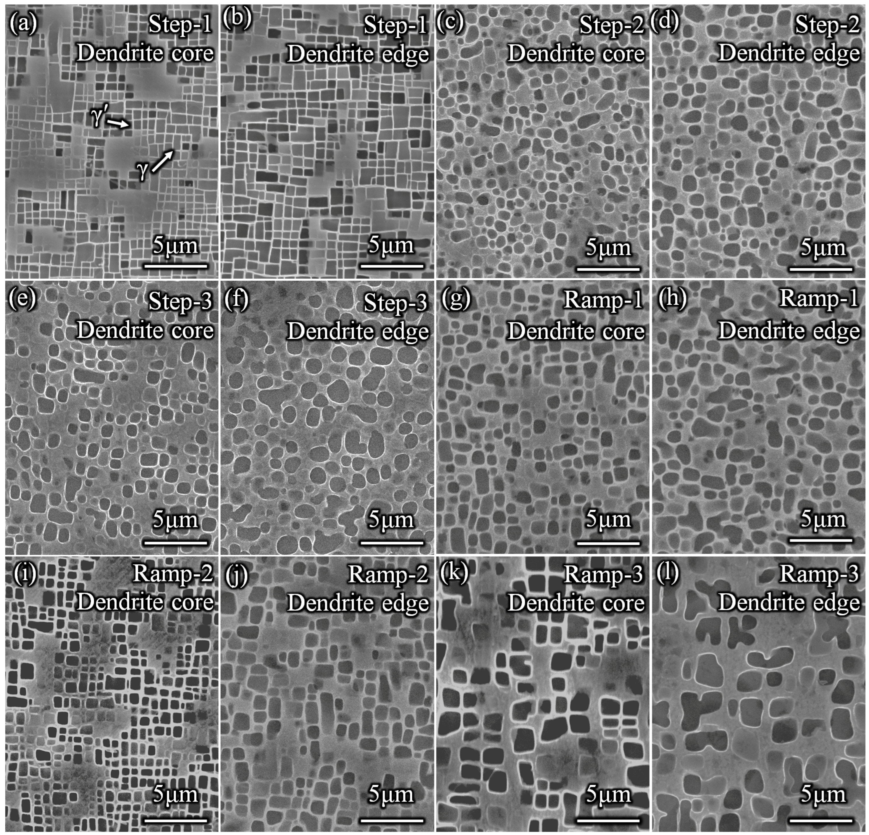
- After different heat treatment procedures, the shape and size of the γ′ phase between the dendritic core and edge regions tend to be the same, with the size difference between these two regions represented by the following sequence: Step-1 < Ramp-2 < Step-2 < Step-3 < Ramp-1 < Ramp-3.
- (2)
- The dissolution degree of the γ′ phase is determined by the thermal solid solution, and the high dissolution degree of γ′ phase decreases the size difference in the γ′ phase between the dendrite core and edge after solid solution treatment.
- (3)
- The degree of dendritic segregation is related to the size difference in the γ′ phase between the dendrite core and edge. The size variation in the γ′ phase is large in the alloy with severe dendritic segregation.
- (4)
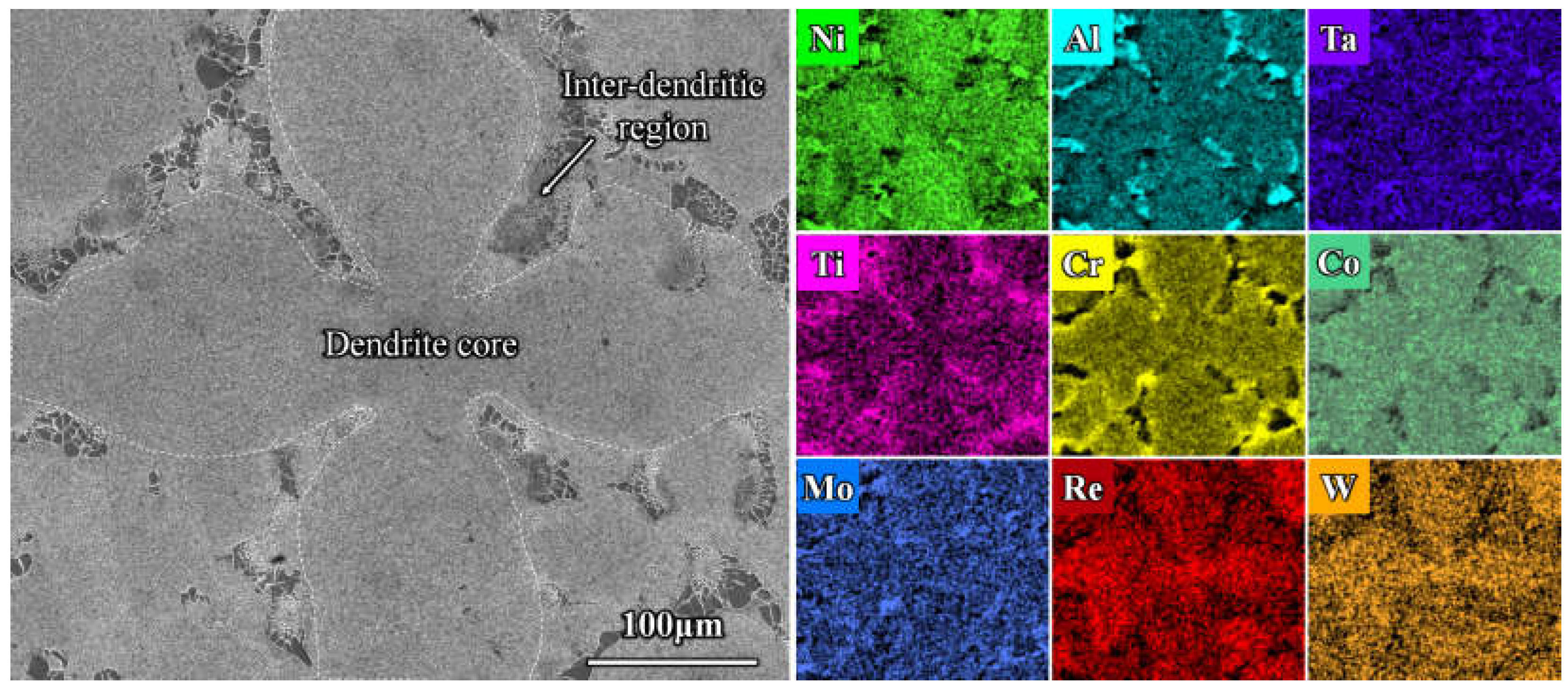
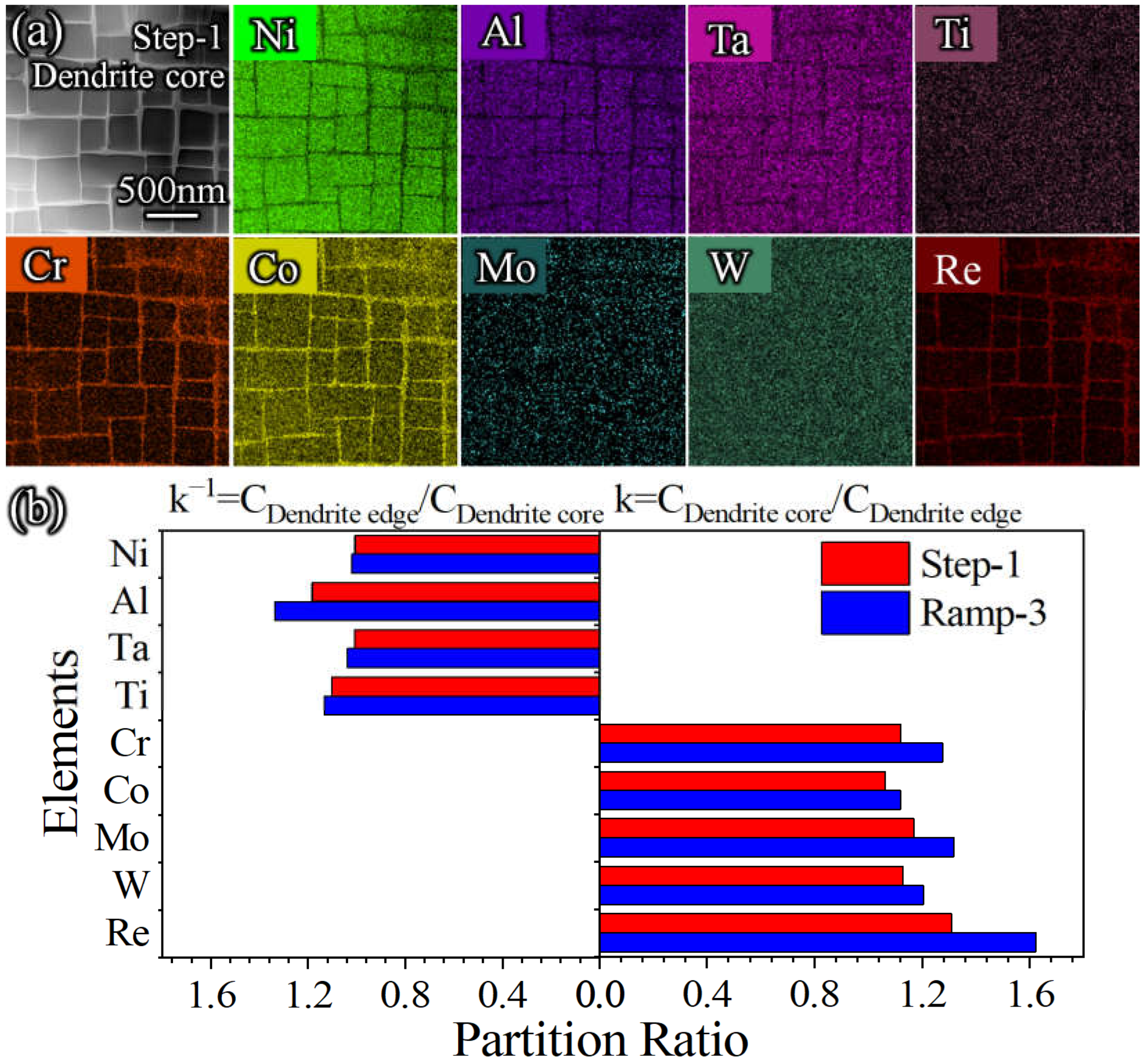
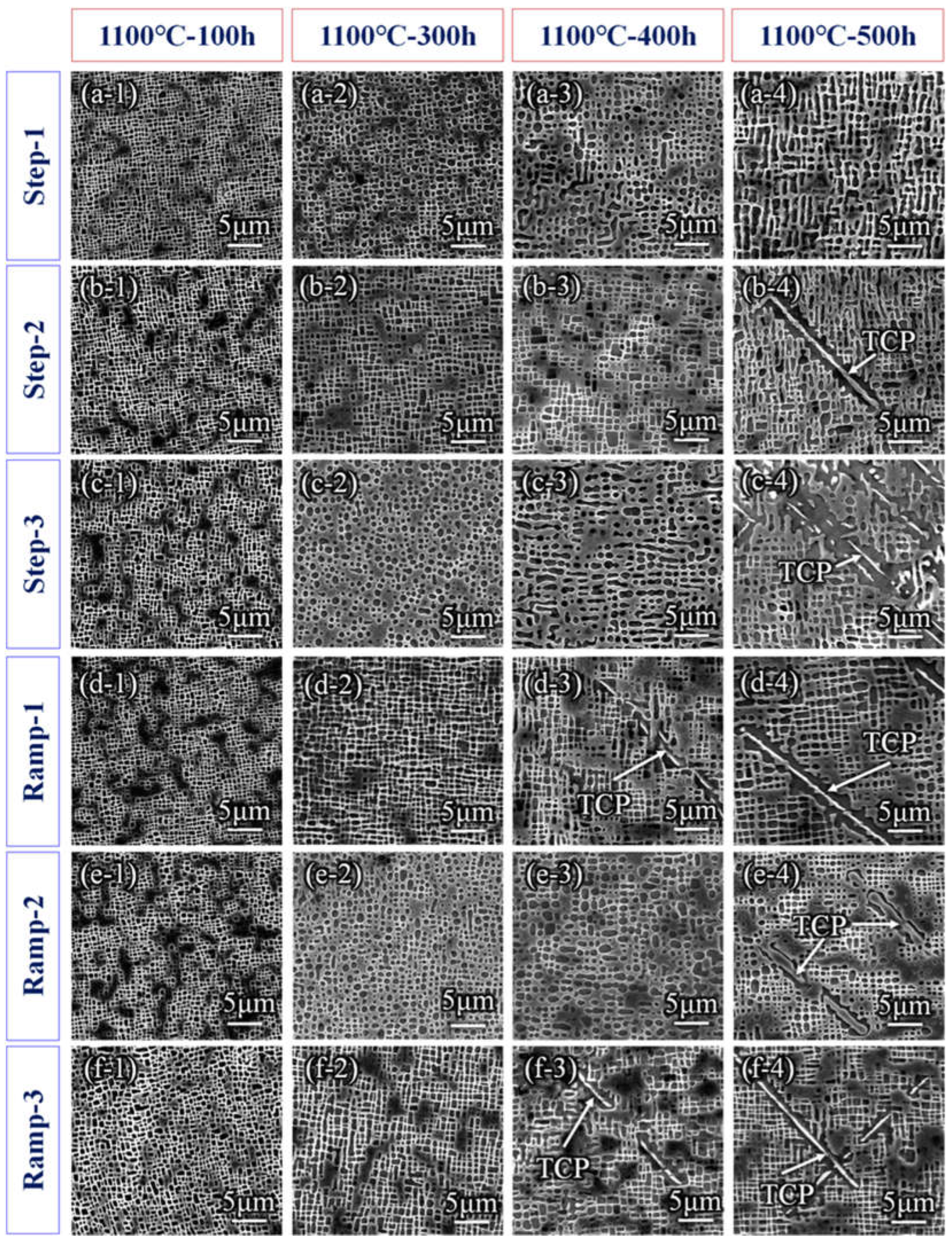
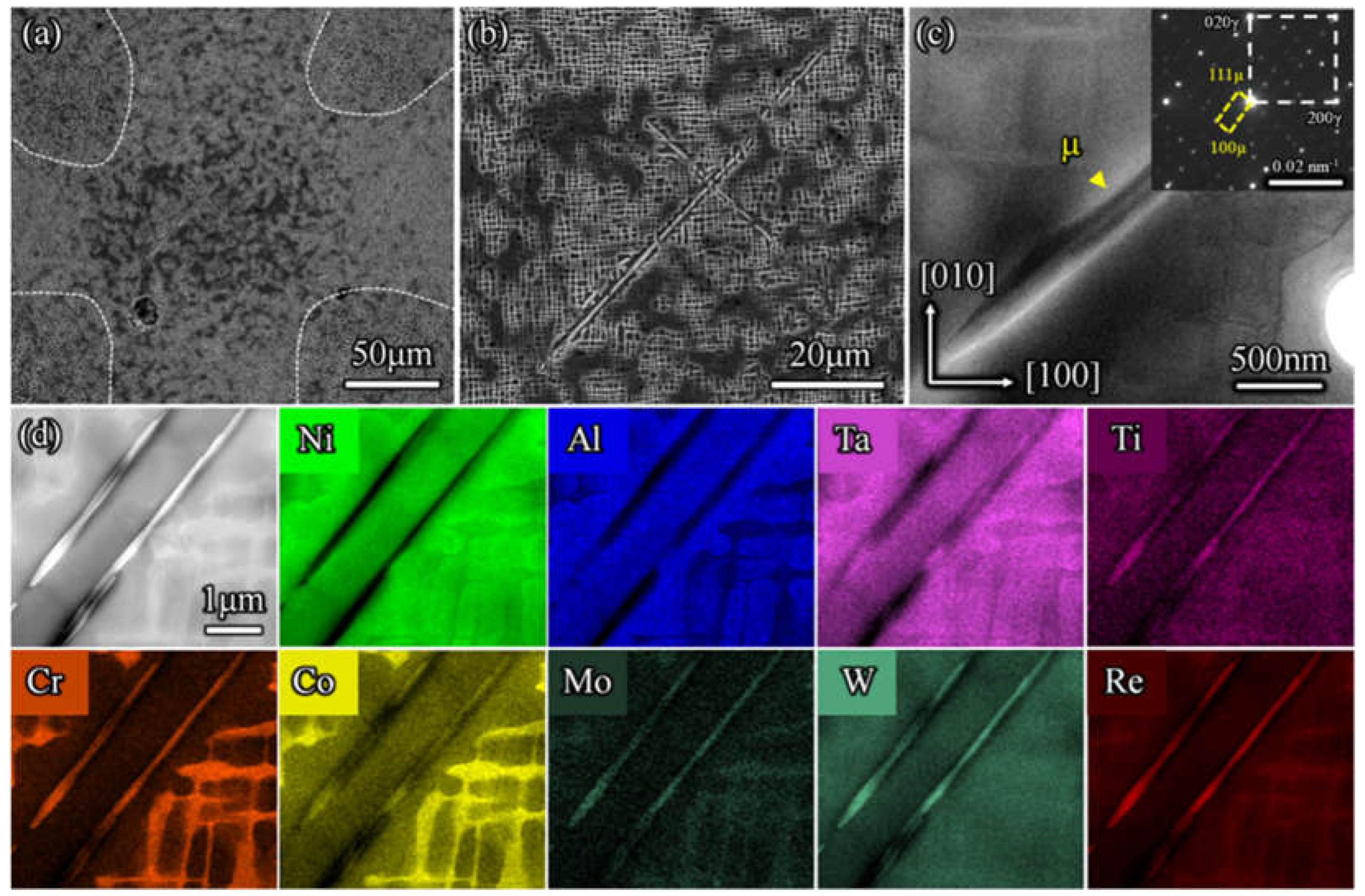
- Dendrite segregation leads to the segregation of refractory elements such as Co, Mo, W, and Re at the dendrite core, which makes the TCP phase easy to nucleate and precipitate at this position during long-term thermal exposure.
- (5)
- The alloy with a long thermal solution time has improved microstructure stability.
Author Contributions
Funding
Data Availability Statement
Conflicts of Interest
References
- Pollock, T.M.; Tin, S. Nickel-Based Superalloys for Advanced Turbine Engines: Chemistry, Microstructure and Properties. J. Propul. Power 2006, 22, 361–374. [Google Scholar] [CrossRef]
- Reed, R.C. The Superalloys: Fundamentals and Applications; Cambridge University Press: New York, NY, USA, 2006. [Google Scholar]
- Kong, W.-W.; Yuan, C.; Zhang, B.-N. Investigations on cyclic deformation behaviors and corresponding failure modes of a Ni-Based superalloy. Mater. Sci. Eng. A 2020, 791, 139775. [Google Scholar] [CrossRef]
- Zhang, J.X.; Harada, H.; Ro, Y.; Koizumi, Y.; Kobayashi, T. Thermomechanical fatigue mechanism in a modern single crystal nickel base superalloy TMS-82. Acta Mater. 2008, 56, 2975–2987. [Google Scholar] [CrossRef]
- Huang, M.; Zhu, J. An overview of rhenium effect in single-crystal superalloys. Rare Met. 2016, 35, 127–139. [Google Scholar] [CrossRef]
- Long, H.; Mao, S.; Liu, Y.; Zhang, Z.; Han, X. Microstructural and compositional design of Ni-based single crystalline superalloys—A review. J. Alloys Compd. 2018, 743, 203–220. [Google Scholar] [CrossRef]
- Tian, N.; Meng, T.; Sun, S.; Zhang, S.; Dang, D. Creep Behavior of a Single Crystal Nickel-Based Superalloy Containing High Concentrations of Re/Ru at an Intermediate Temperature. Crystals 2024, 14, 983. [Google Scholar] [CrossRef]
- Pyczak, F.; Devrient, B.; Neuner, F.C.; Mughrabi, H. The influence of different alloying elements on the development of the γ/γ′ microstructure of nickel-base superalloys during high-temperature annealing and deformation. Acta Mater. 2005, 53, 3879–3891. [Google Scholar] [CrossRef]
- Volek, A.; Pyczak, F.; Singer, R.F.; Mughrabi, H. Partitioning of Re between γ and γ′ phase in nickel-base superalloys. Scr. Mater. 2005, 52, 141–145. [Google Scholar] [CrossRef]
- Sato, A.; Harada, H.; Yokokawa, T.; Murakumo, T.; Koizumi, Y.; Kobayashi, T.; Imai, H. The effects of ruthenium on the phase stability of fourth generation Ni-base single crystal superalloys. Scr. Mater. 2006, 54, 1679–1684. [Google Scholar] [CrossRef]
- Hobbs, R.A.; Zhang, L.; Rae, C.M.F.; Tin, S. Mechanisms of Topologically Close-Packed Phase Suppression in an Experimental Ruthenium-Bearing Single-Crystal Nickel-Base Superalloy at 1100 °C. Metall. Mater. Trans. A 2008, 39, 1014–1025. [Google Scholar] [CrossRef]
- Wang, D.; Zhang, J.; Lou, L.H. On the role of μ phase during high temperature creep of a second generation directionally solidified superalloy. Mater. Sci. Eng. A 2010, 527, 5161–5166. [Google Scholar] [CrossRef]
- Tan, X.P.; Liu, J.L.; Jin, T.; Hu, Z.Q.; Hong, H.U.; Choi, B.G.; Kim, I.S.; Jo, C.Y. Intergrowth of P phase with µ phase in a Ru-containing single-crystal Ni-based superalloy. Philos. Mag. Lett. 2012, 92, 556–562. [Google Scholar] [CrossRef]
- Long, H.; Liu, Y.; Mao, S.; Wei, H.; Zhang, J.; Ma, S.; Deng, Q.; Chen, Y.; Zhang, Z.; Han, X. Effect of chemical composition on particle morphology of topologically close-packed precipitates in a Ni-based single crystal superalloy. Scr. Mater. 2018, 157, 100–105. [Google Scholar] [CrossRef]
- Long, H.; Mao, S.; Liu, Y.; Wei, H.; Deng, Q.; Chen, Y.; Zhang, Z.; Han, X. Effect of pre-straining treatment on high temperature creep behavior of Ni-based single crystal superalloys. Mater. Des. 2019, 167, 107633. [Google Scholar] [CrossRef]
- Giamei, A.F.; Tschinkel, J.G. Liquid metal cooling: A new solidification technique. Metall. Mater. Trans. A 1976, 7, 1427–1434. [Google Scholar] [CrossRef]
- Elliott, A.J.; Pollock, T.M.; Tin, S.; King, W.T.; Huang, S.C.; Gigliotti, M.F.X. Directional solidification of large superalloy castings with radiation and liquid-metal cooling: A comparative assessment. Metall. Mater. Trans. A 2004, 35, 3221–3231. [Google Scholar] [CrossRef]
- Wang, F.; Ma, D.X.; Zhang, J.; Bogner, S.; Bührig-Polaczek, A. A high thermal gradient directional solidification method for growing superalloy single crystals. J. Mater. Process. Technol. 2014, 214, 3112–3121. [Google Scholar] [CrossRef]
- Wei, J.; Lu, M.; Pi, L.; Zhao, H.; Lei, Q. Numerical Simulation Study on Directional Solidification of DD5 Nickel-Based Single-Crystal Turbine Blades. Crystals 2025, 15, 42. [Google Scholar] [CrossRef]
- Wang, H.; Su, H.; Zhang, J.; Guomin; Zhang, Y.; Yue, Q.; Liu, L.; Huang, T.; Yang, W.; Fu, H. Investigation on solidification path of Ni-based single crystal superalloys with different Ru contents. Mater. Charact. 2017, 130, 211–218. [Google Scholar] [CrossRef]
- Cao, K.; Yang, W.; Zhang, J.; Liu, C.; Qu, P.; Su, H.; Zhang, J.; Liu, L. Solidification characteristics and as-cast microstructures of a Ru-containing nickel-based single crystal superalloy. J. Mater. Res. Technol. 2021, 11, 474–486. [Google Scholar] [CrossRef]
- Pan, Q.; Zhao, X.; Yue, Q.; Xia, W.; Gu, Y.; Ding, Q.; Zhang, Z. Effects of Cobalt on solidification characteristics and as-cast microstructure of an advanced nickel-based single crystal superalloys. J. Mater. Res. Technol. 2022, 20, 3074–3082. [Google Scholar] [CrossRef]
- Wang, X.-Y.; Wen, Z.-X.; Cheng, H.; Gu, S.-N.; Lu, G.-X. Influences of the Heating and Cooling Rates on the Dissolution and Precipitation Behavior of a Nickel-Based Single-Crystal Superalloy. Metals 2019, 9, 360. [Google Scholar] [CrossRef]
- Du, Y.; Yang, Y.; Diao, A.; Li, Y.; Wang, X.; Zhou, Y.; Li, J.; Sun, X. Effect of solution heat treatment on creep properties of a nickel-based single crystal superalloy. J. Mater. Res. Technol. 2021, 15, 4702–4713. [Google Scholar] [CrossRef]
- Huang, J.; Ai, C.; Ru, Y.; Shang, Y.; Pei, Y.; Li, S.; Gong, S.; Zhang, H. The Effect of Cooling Rate from Solution Treatment on γ′ Reprecipitates and Creep Behaviors of a Ni-Based Superalloy Single-Crystal Casting. Crystals 2022, 12, 1235. [Google Scholar] [CrossRef]
- Hegde, S.R.; Kearsey, R.M.; Beddoes, J.C. Designing homogenization–solution heat treatments for single crystal superalloys. Mater. Sci. Eng. A 2010, 527, 5528–5538. [Google Scholar] [CrossRef]
- Zhang, Y.; Liu, L.; Huang, T.; Yue, Q.; Sun, D.; Zhang, J.; Yang, W.; Su, H.; Fu, H. Investigation on a ramp solution heat treatment for a third generation nickel-based single crystal superalloy. J. Alloy. Compd. 2017, 723, 922–929. [Google Scholar] [CrossRef]
- Liu, P.; Liu, X.; Huang, Y.; Wang, L.; Li, H.; Lou, L. Effect of heating processing on the formation of micro-pores during solution treatment of high generation nickel-based single crystal superalloy. Mater. Charact. 2022, 189, 111994. [Google Scholar] [CrossRef]
- Pang, H.T.; D’Souza, N.; Dong, H.; Stone, H.J.; Rae, C.M.F. Detailed Analysis of the Solution Heat Treatment of a Third-Generation Single-Crystal Nickel-Based Superalloy CMSX-10K®. Metall. Mater. Trans. A 2016, 47, 889–906. [Google Scholar] [CrossRef]


| Elements | Co | Cr | Mo | W | Re | Al | Ti | Ta | Ni |
|---|---|---|---|---|---|---|---|---|---|
| wt. % | 10.0 | 4 | 1 | 6.0 | 5 | 6 | 1 | 8.5 | Bal. |
| Type | Symbol | Heat Treatment Procedure |
|---|---|---|
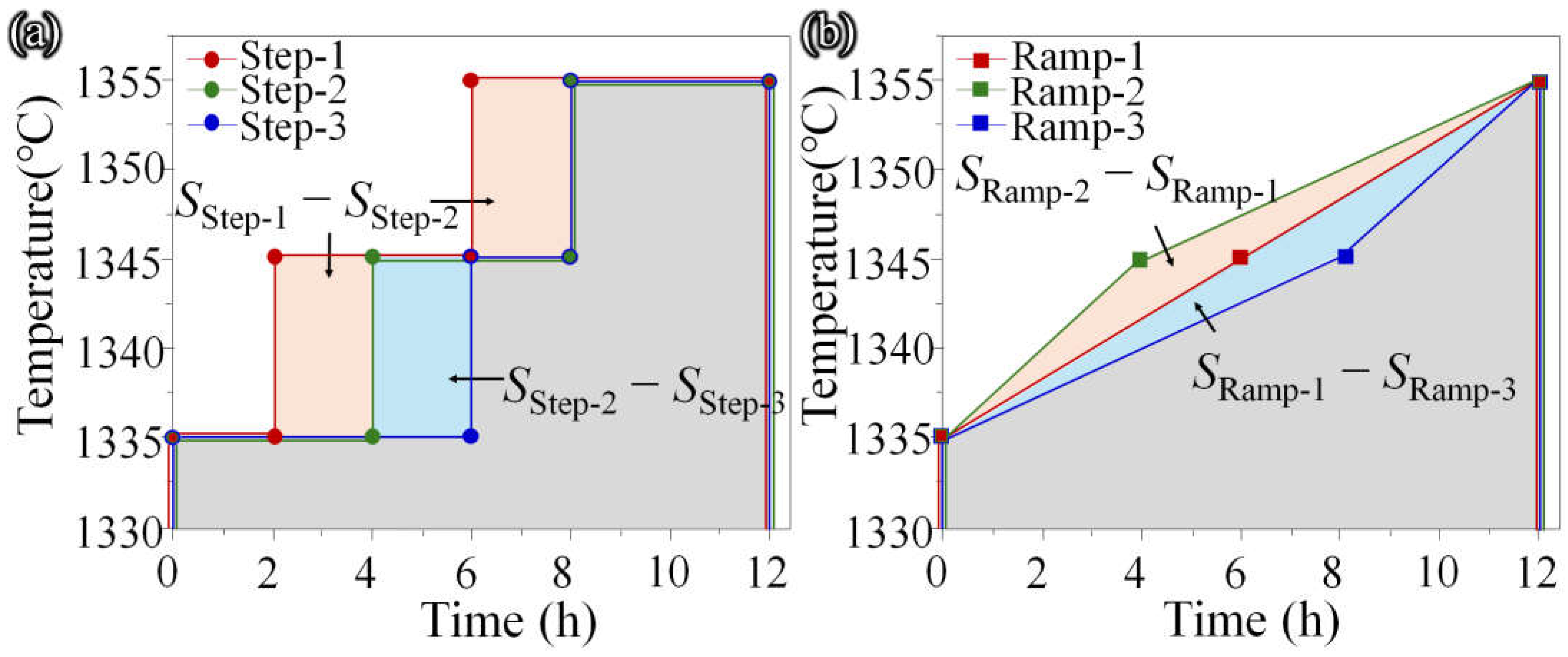
| Step solution | Step-1 | 1335 °C/2 h + 1345 °C/4 h + 1355 °C/6 h |
| Step-2 | 1335 °C/4 h + 1345 °C/4 h + 1355 °C/4 h | |
| Step-3 | 1335 °C/6 h + 1345 °C/2 h + 1355 °C/4 h | |
| Ramp solution | Ramp-1 | 1335 °C→1.67 °C/h→1345 °C→1.67 °C/h→1355 °C |
| Ramp-2 | 1335 °C→2.5 °C/h→1345 °C→1.25 °C/h→1355 °C | |
| Ramp-3 | 1335 °C→1.25 °C/h→1345 °C→2.5 °C/h→1355 °C |
Disclaimer/Publisher’s Note: The statements, opinions and data contained in all publications are solely those of the individual author(s) and contributor(s) and not of MDPI and/or the editor(s). MDPI and/or the editor(s) disclaim responsibility for any injury to people or property resulting from any ideas, methods, instructions or products referred to in the content. |
© 2025 by the authors. Licensee MDPI, Basel, Switzerland. This article is an open access article distributed under the terms and conditions of the Creative Commons Attribution (CC BY) license (https://creativecommons.org/licenses/by/4.0/).
Share and Cite
Yang, G.; Sun, M.; Chen, Y.; Long, H. Effect of Solid Solution Treatment Routes on the Microstructure Configuration of a Third-Generation Ni-Based Superalloy. Crystals 2025, 15, 303. https://doi.org/10.3390/cryst15040303
Yang G, Sun M, Chen Y, Long H. Effect of Solid Solution Treatment Routes on the Microstructure Configuration of a Third-Generation Ni-Based Superalloy. Crystals. 2025; 15(4):303. https://doi.org/10.3390/cryst15040303
Chicago/Turabian StyleYang, Guo, Ming Sun, Yanhui Chen, and Haibo Long. 2025. "Effect of Solid Solution Treatment Routes on the Microstructure Configuration of a Third-Generation Ni-Based Superalloy" Crystals 15, no. 4: 303. https://doi.org/10.3390/cryst15040303
APA StyleYang, G., Sun, M., Chen, Y., & Long, H. (2025). Effect of Solid Solution Treatment Routes on the Microstructure Configuration of a Third-Generation Ni-Based Superalloy. Crystals, 15(4), 303. https://doi.org/10.3390/cryst15040303