Article

Modification of Lithium-Rich Layered Material Li1.5Ni0.17Co0.16Mn0.67O2.5 Coated with Solid Electrolyte (Li2ZrO3)

1
College of Physics and Electronic Information, Inner Mongolia Normal University, Hohhot 010022, China
2
Inner Mongolia Key Laboratory of Applied Condensed Matter Physics, Hohhot 010022, China
3
Engineering Research Center of New Energy Storage Materials, Universities of Inner Mongolia Autonomous Region, Hohhot 010022, China
*
Author to whom correspondence should be addressed.
Crystals 2025, 15(3), 262; https://doi.org/10.3390/cryst15030262
Submission received: 25 January 2025 / Revised: 21 February 2025 / Accepted: 27 February 2025 / Published: 11 March 2025
(This article belongs to the Section Materials for Energy Applications)

Abstract

:
With the rising popularity of electric vehicles and the widespread deployment of energy storage power stations. The demand for high-energy-density lithium-ion batteries is increasing day by day. Lithium-rich layered materials are among the most promising candidates for the cathode of next-generation lithium-ion batteries due to their high energy density, cost-effectiveness, and advantages in safety and environmental protection. However, the occurrence of side reactions between lithium-rich layered materials and electrolytes has led to poor performance in later stages, posing challenges to their commercial viability. In this study, we enhance the electrochemical performance of lithium-rich layered cathode materials by applying varying amounts of solid electrolyte Li2ZrO3 as a coating on their surfaces. By precipitating ZrO2 onto the surface of the precursor, we successfully sinter both the lithium-rich layered material and the coated material simultaneously, thereby reducing processing costs. The experimental results show that the coated material has more excellent electrochemical performance, specifically, when the coating amount is 1%, compared with the uncoated sample, the first Coulombic efficiency is improved from 56.9% to 63%, and after 500 charge/discharge cycles, the coated sample still has a capacity retention rate of more than 60%; Additionally, the Li2ZrO3 coating significantly improves the rate performance of the material, at a rate of 5 C, the specific discharge capacity improved from 102.2 mAh·g−1 for the uncoated material to 137.3 mAh·g−1. The reaction mechanism was investigated by cyclic voltammetry and AC impedance test, and the results showed that the appropriate amount of Li2ZrO3 coating can effectively reduce the side reaction between the material and the electrolyte, improve the transport performance of lithium ions in the material, and then enhance the overall electrochemical performance of the material.

1. Introduction

The rapid development of small digital devices, particularly mobile phones, as well as larger applications such as electric vehicles and energy storage power stations, has led to an increased demand for higher energy density in lithium-ion batteries. Fundamentally, the energy density of a lithium-ion battery is determined by the potential difference between the positive and negative electrodes, along with the reversible capacity [1]. However, the capacity of commercially available anode materials is several times greater than that of the currently available cathode materials [2]. The existing commercial cathode materials, including LiFePO4, LiCoO2, and ternary LiNi1−x−yCoxMnyO2, are approaching their maximum energy density limits. Consequently, the development of cathode materials that offer high energy density, long cycle life, and low cost has become a primary focus of contemporary research.
The lithium-rich layered material xLi2MnO3·(1−x)LiTMO2 (where TM represents transition metal elements) has emerged as one of the most promising next-generation cathode materials for commercial lithium-ion batteries, owing to its high specific capacity (>250 mAh·g−1) and low cost [3,4,5]. The structural formula indicates that this lithium-rich layered material comprises LiTMO2 in a hexagonal crystal system combined with Li2MnO3 in a monoclinic crystal system [6,7,8]. In the coexistence of these two phases, the Li2MnO3 phase not only stabilizes the structure at low voltages but is also activated when the voltage exceeds 4.5 V, enabling the material to achieve a specific capacity greater than 250 mAh·g−1 [9,10].
However, upon activation of the Li2MnO3 composition, the lithium-rich layered material experiences irreversible migration of transition metal ions from the transition metal layer to the lithium layer during the charging process. Concurrently, surface O2− ions are irreversibly released [11], resulting in a structural transformation from a layered to a spinel-like configuration. This transformation leads to initial electrochemical issues, such as low Coulombic efficiency, rapid voltage degradation, and diminished rate performance [12,13,14]. In order to address these issues, investigators have explored various methods of modifying lithium-rich layered materials. Some have introduced other atoms into the bulk phase of the material to improve the stability of the material structure by increasing the bonding energy between the dopant ions and and the oxygen ions, which in turn improves the initial Coulombic efficiency and cycling stability of the material [15,16,17]; others have investigated the surface pretreatment method, which reduces the irreversible loss of oxygen through the formation of defects on the surface of the material, thus improving its electrochemical performance [18,19]. In addition, surface coating is a very effective modification means in the research related to lithium-ion materials, which reduces the side reaction between the electrode material and electrolyte by reducing the contact area, and thus improves the rate performance and cycle stability [20,21,22]. In previous studies, Ga2O3, Li2SO3 and other materials have been coated on the surface of Li-rich manganese materials with good modification effect [23,24]. In previous studies, researchers have paid less attention to the first Coulombic efficiency. Li2ZrO3 is a common electrode material, whose (001) crystal spacing is similar to that of (003) crystal spacing of LiMO2 (M = Ni, Co, Mn), so that Li+ can pass through the Li2ZrO3 capping layer quickly. Currently, there are few studies on the modification of Li2ZrO3 as a surface capping material applied to Li-rich manganese-based materials. In this paper, we enhance the performances of lithium rich layered materials Li1.5Ni0.17Co0.16Mn0.67O2.5 coated with solid electrolyte (Li2ZrO3).

2. Materials and Methods

Preparation of Samples

Initially, metal salts such as NiSO4·6H2O, CoCl2·6H2O, and MnCl2 were dissolved in an appropriate amount of deionized water to prepare solution A. Separately, a certain amount of NaOH is weighed according to the stoichiometric ratio and dissolved in deionized water to produce solution B. Once both solutions were completely dissolved, solution B was slowly introduced into solution A using a peristaltic pump, resulting in the formation of a precipitate. Then, the mixture at the end of the reaction was vacuum filtered to obtain the precursor precipitate. The filtered precipitate was repeatedly washed three times with deionized water to remove water-soluble Na+ adhered to the surface. Finally, the washed precipitate was dried in a drying oven at 80 ° C for 10 h to obtain the powder precursor. The precursor was subsequently mixed with an excess of 5% Li2CO3 and thoroughly milled. The ground solid mixture is placed in a muffle furnace and heated in two steps under an air atmosphere: first, it was pre-sintered at 600 °C for 6 h, followed by sintering at 800 °C for 8 h. Finally, the lithium-rich layered material Li1.5Ni0.17Co0.16Mn0.67O2.5 was obtained through natural cooling.
An appropriate amount of precursor powder was weighed and placed in a beaker, to which a suitable quantity of anhydrous ethanol and deionized water was added. The beaker was then heated to 80 °C, after which an appropriate amount of ethylene glycol and n-butyl zirconium was gradually introduced. Following 12 h of stirring on a magnetic stirrer, the material was transferred to an oven for drying at 80 °C. The dried precursor was subsequently milled thoroughly with an excess of 5% Li2CO3, and then placed in a muffle furnace under an air atmosphere for a two-stage sintering process. Initially, it was pre-sintered at 600 °C for 6 h, followed by sintering at 800 °C for 8 h. After sintering, the material was dried in an oven at 80 °C. Ultimately, natural cooling resulted in the formation of Li2ZrO3-coated Li1.5Ni0.17Co0.16Mn0.67O2.5 materials with coating percentages of 0 wt%, 1 wt%, 3 wt%, and 5 wt%. These materials will be referred to hereinafter as LNCM, Zr-LNCM-1, Zr-LNCM-3, and Zr-LNCM-5, respectively.
(a)
Material characterization
The material structure was characterized using an X-ray diffractometer with a scanning angle ranging from 10 ° to 90 ° in increments of 0.01 °, utilizing Cu Kα radiation (XRD, Panaco Empyrean, Almelo, The Netherlands). The surface morphology and elemental distribution of the samples were analyzed using a transmission electron microscope (TEM, JEM-2100F, Tokyo, Japan), a scanning electron microscope (SEM, Hitachi SU8010, Tokyo, Japan), and an energy dispersive spectrometer (EDS, IXRF, Tianjin, China).
(b)
Electrochemical testing of materials
The cathode material, conductive graphite, and polyvinylidene fluoride were mixed in 1-methyl-2-pyrrolidone (NMP) at a mass ratio of 8:1:1 and stirred thoroughly. The resulting slurry was then uniformly coated onto aluminum foil and dried overnight in an oven at 80 °C to produce the cathode electrode sheets. These electrode sheets were subsequently placed in an argon-filled glove box and assembled into LIR2032-type button cells for testing their electrochemical properties. The batteries were charged and discharged at various rates between 2 and 4.8 V using a LANG (CT2001A, LANHE, Wuhan, China) blue power test system. Electrochemical impedance analysis and cyclic voltammetry were conducted using an electrochemical workstation (CHI760E, Zhenhua Instruments, Shanghai, China).

3. Results and Discussion

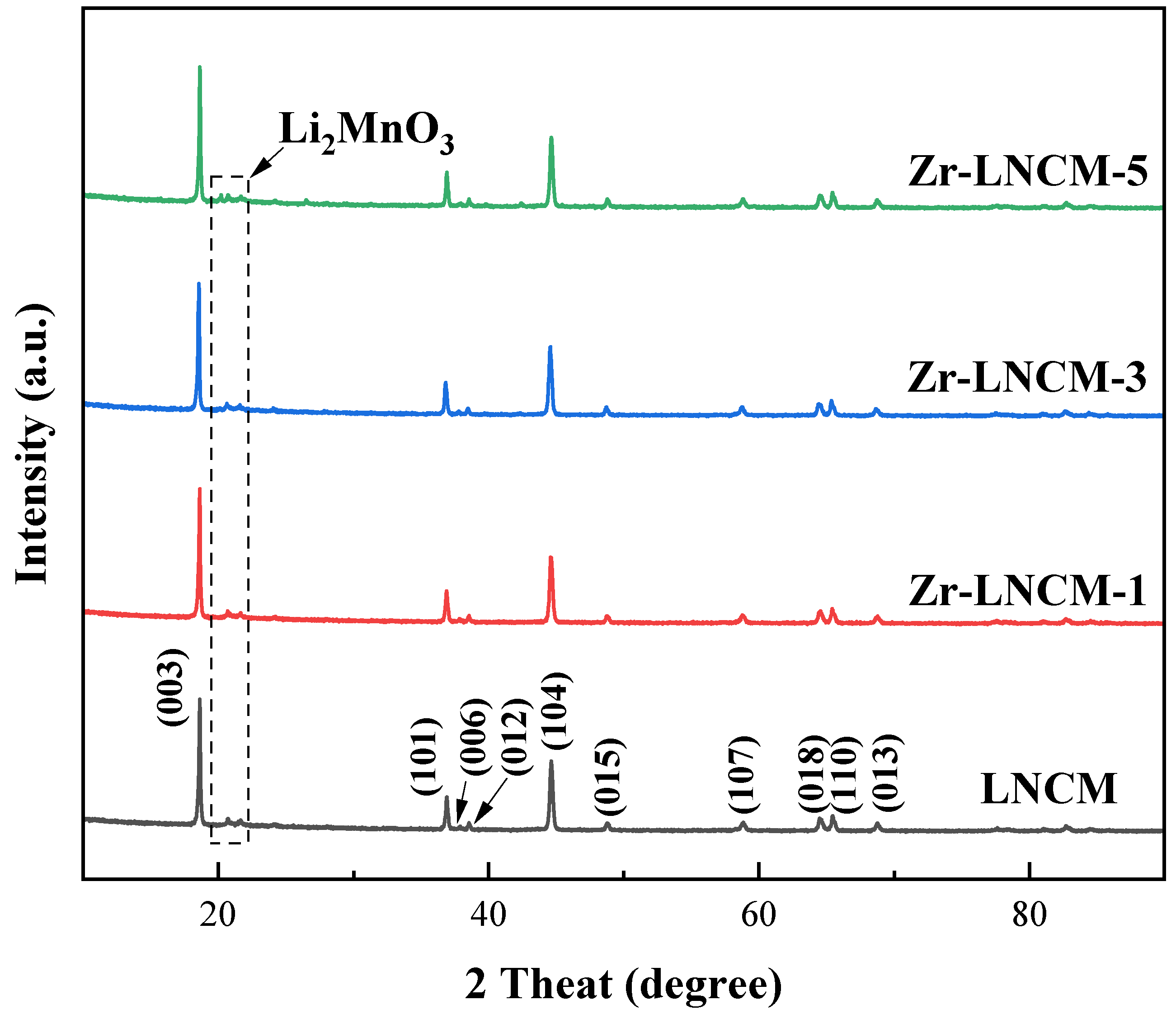
3.1. Crystal Structure

Figure 1 presents the XRD diffractograms of four groups of samples before and after coating. The diffraction patterns indicate that all four groups exhibit typical lamellar α-NaFeO2 phases, which belong to the R-3m space group [25]. In contrast, the low-intensity superlattice diffraction peaks observed in the 21°and 23°can be attributed to the Li2MnO3 phase, characterized by a C2/m space group, as well as the ordered arrangement of Li, Ni, and Mn atoms within the transition metal layer [26]. Furthermore, a distinct separation between the peaks adjacent to (006)/(102) and (018)/(110) is clearly visible in the graph, suggesting that the material possesses a well-defined lamellar structure [27]. Comparing the XRD diagrams of the four groups of samples reveals that the structure of the lithium-rich layered material Li1.5Ni0.17Co0.16Mn0.67O2.5 remains unchanged before and after the Li2ZrO3 coating, indicating that the application of Li2ZrO3 does not affect the structural integrity of the lithium-rich layered material. Additionally, structural refinement was performed on the samples before and after coating, with the resulting lattice parameters presented in Table 1. Typically, we utilize the peak intensity ratio of I(003)/I(104) to assess the degree of Li/Ni mixing and rearrangement within the material, and the c/a ratio to evaluate the quality of the material’s lamellar structure [28,29]. According to the data in Table 1 and Table 2, it is evident that the degree of Li/Ni mixing and rearrangement is influenced to some extent by the coating dosage of Li2ZrO3; however, the lamellar structure of the material appears to be insensitive to variations in the Li2ZrO3 coating dosage, and the structural information remained unchanged before and after encapsulation. In addition, no characteristic peaks corresponding to Li2ZrO3 were detected in the XRD diffraction pattern, due to the fact that the amount of coating material is very small compared to the matrix material, and the XRD detection is not sensitive to the amount and its tiny composition, so the XRD pattern of all samples does not change significantly.

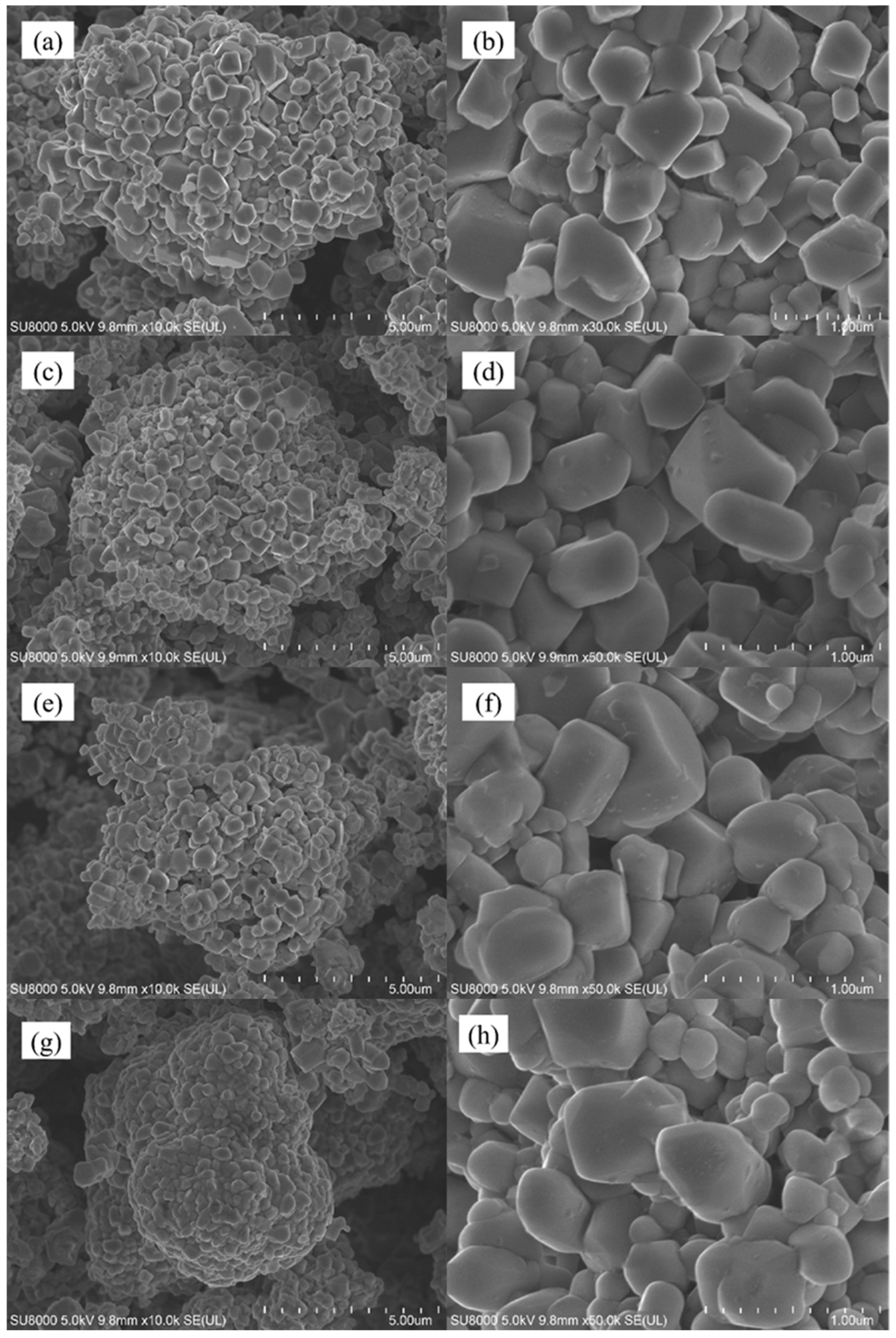
3.2. Morphology and Surface Composition

Subsequently, the surface morphology of the material was characterized, as illustrated in Figure 2, which presents scanning electron microscope (SEM) images of the Li1.5Ni0.17Co0.16Mn0.67O2.5 lithium-rich layered material before and after Li2ZrO3 coating. From the figure, it is evident that the morphology of the material did not change significantly after modification; it retains an irregular polyhedral shape. However, there are still some differences on the surface of the samples before and after coating. From the figure, we can see that the samples without coating and with less coating have smoother surfaces and more obvious particle separation; With the increase of coating amount, the surface of the sample begins to become rough, and some small particles begin to adhere to the surface of large particles. At the same time, the sample begins to agglomerate, and with the increase of coating amount, the agglomeration of sample particles becomes more compact; This indicates that appropriate coating can effectively reduce the direct contact between the electrolyte and the material. However, when the coating amount is too high and the coating layer is too thick, the specific surface area of the material in contact with the electrolyte decreases, which may reduce the conductivity of the material, thereby reducing its electrochemical performance. In order to further study the distribution of surface elements of different materials before and after coating, energy dispersive spectroscopy (EDS) tests were carried out on two materials, LNCM, which was uncoated, and Zr-LNCM-1, which was coated with 1 wt%. The results of the EDS analysis are shown in Figure 3. The results of the EDS analysis are shown in Figure 3. It is noteworthy that the detection of the Li element was not performed due to its small atomic weight, which limits accurate measurement [30]. As shown in Figure 3b, the elements Ni, Co, Mn, and Zr are uniformly distributed throughout the material, with Zr exhibiting a consistent distribution across all areas, indicating that the coating material is evenly applied to the surface. And the composition of the prepared sample is uniform and consistent. To further examine the microstructure of the materials before and after coating, high-resolution transmission electron microscopy (HRTEM) tests were conducted on four sets of samples. Figure 4 demonstrates that the thickness of the coating layer increases with the amount of coating material. The surface of the uncoated sample appears relatively smooth, and clear lattice fringes of the (003) plane are observed, with a crystal spacing of 0.46154 nm, as shown in Figure 4e. In Figure 4c, the surface of the material coated with Li2ZrO3 exhibits a thin coating layer, which thickens as the coating amount increases. Upon further magnification of the material coated with 1 wt% Li2ZrO3, the presence of the coating layer is clearly visible in Figure 4f. This indicates that the Li2ZrO3 is successfully coated on the surface of the material without entering the crystal lattice to change the crystal structure of the material. Additionally, the lattice fringes on the crystal surface of the lithium-rich material (003) remain observable, with a crystal spacing of 0.45358 nm, suggesting minimal change in crystal spacing before and after coating. However, no lattice fringes of the coating material were detected, which may be attributed to the thinness of the coating layer, rendering the lattice fringes less discernible.

4. Electrochemical Performance Analysis

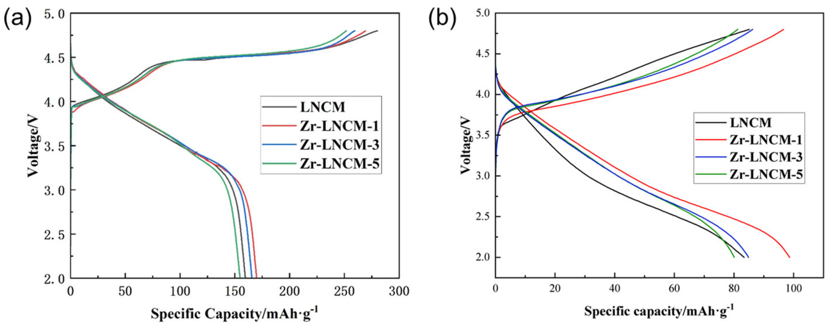
4.1. Initial Charge/Discharge and Coulombic Efficiency

Figure 5a presents the initial charge-discharge curves of the four samples at a charge-discharge current density of 0.2 C at room temperature. As shown in the figure, the charge-discharge characteristics of the samples before and after coating did not exhibit significant changes. All samples displayed two typical charging regions: when the charging voltage was below 4.5 V, Li+ ions were extracted from LiTMO2, accompanied by the oxidation of transition metals, where Ni2+/Ni3+ was oxidized to Ni4+, and Co3+ was oxidized to Co4+. However, when the charging voltage exceeded 4.5 V, the Li2MnO3 component began to activate, resulting in the irreversible extraction of Li+ from Li2MnO3, which formed Li2O with O2− ions. This process led to the irreversible release of O2− and Li+, contributing to a reduction in the initial specific capacity performance of the material [31,32]. According to Table 3, the initial discharge specific capacities of LNCM, Zr-LNCM-1, Zr-LNCM-3, and Zr-LNCM-5 at a 0.2 C rate were 159.6 mAh·g−1, 169.9 mAh·g−1, 165.6 mAh·g−1, and 154.8 mAh·g−1, respectively. The irreversible capacity of LNCM was measured at 101 mAh·g-1, while the irreversible capacities of Zr-LNCM-1 and Zr-LNCM-3 were 99.5 mAh·g−1 and 93.9 mAh·g−1, respectively. The initial Coulombic efficiencies of the materials improved from 56.9% to 63% and 63.8%, respectively. This enhancement can be attributed to the capping materials’ ability to hinder the irreversible release of lattice oxygen, thereby improving the electrochemical performance of the materials. Figure 5b shows the charge/discharge curves of different materials after 500 cycles, from which it can be seen that the capacity retention rates of LNCM, Zr-LNCM-1, Zr-LNCM-3, and Zr-LNCM-5 are 54%, 60%, 57%, and 48%, respectively, and that the samples with a coating amount of 1% have the best capacity retention rates. The best capacity retention was achieved with 1% coating.The discharge voltage plateau of all the materials showed a significant decay with the increase of charging and discharging times, but the voltage decay was significantly slowed down with the coated materials. Therefore, the appropriate amount of Li2ZrO3 coating can help to improve the cycling stability of the materials and make the materials show better electrochemical performance. Table 4 demonstrates the changes in some electrochemical properties of several materials before and after coating, and it can be seen that compared with the uncoated material, the Li2ZrO3 material coating has the advantage of being able to improve its cycling stability without decreasing the initial specific capacity of discharge, and it can significantly increase the first-time Coulombic efficiency.

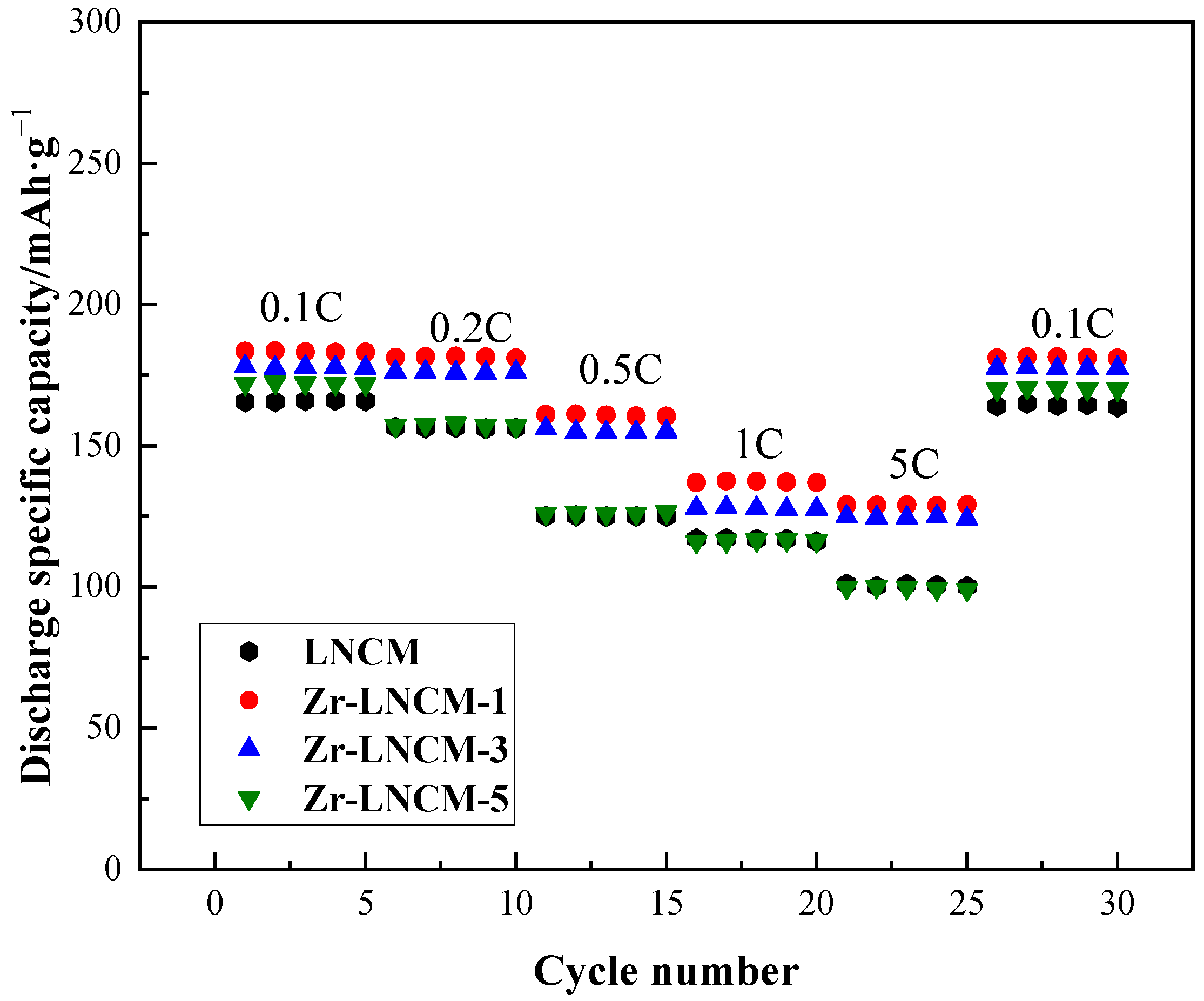
4.2. Rate Performance Analysis

Figure 6 illustrates the rate performance of the lithium-rich layered material before and after coating. The samples were initially activated at room temperature for five cycles at a discharge rate of 0.1 C, followed by five cycles at discharge rates of 0.2 C, 0.5 C, 1 C, and 5 C, respectively. Then, each sample was charged and discharged at a rate of 0.1 C for 5 cycles. From the graphs, it is evident that the discharge specific capacity of all samples decreases with increasing discharge current, likely due to the heightened polarization within the cell at higher currents [33]. The discharge specific capacities of the uncoated samples were measured at 165.4 mAh·g−1 and 156.4 mAh·g−1 at discharge rates of 0.1 C and 0.2 C, respectively. These values were comparable to those of the 3 wt% coated samples and were only surpassed by the 1 wt% coated samples. However, as the discharge rate increased to 1 C and 5 C, the discharge specific capacity of the uncoated samples declined more significantly than that of the coated samples. This phenomenon may be attributed to the formation of a thicker solid electrolyte interphase (SEI) film on the electrode surface of the uncoated samples at high currents, which increases electrode resistance and charge impedance, leading to a more rapid decline in capacity at elevated rates. In contrast, the modified samples exhibited a notable improvement in specific capacity at discharge rates of 1 C and 5 C, particularly for the 1 wt% coated samples. The discharge specific capacities of the 1 wt% coated samples were recorded at 183.2 mAh·g−1 and 137.3 mAh·g−1 at discharge rates of 0.1 C and 5 C, respectively. Upon returning to the 0.1 C discharge rate after 25 cycles, the specific capacity of the 1 wt% coated sample was significantly higher than that of the other samples and was nearly identical to that observed during its initial activation at 0.1 C. Therefore, it can be concluded that an appropriate Li2ZrO3 coating effectively inhibits the formation of a thicker SEI film under high current conditions, thereby enhancing the structural stability of lithium-rich materials and significantly improving the rate performance of the electrode materials.

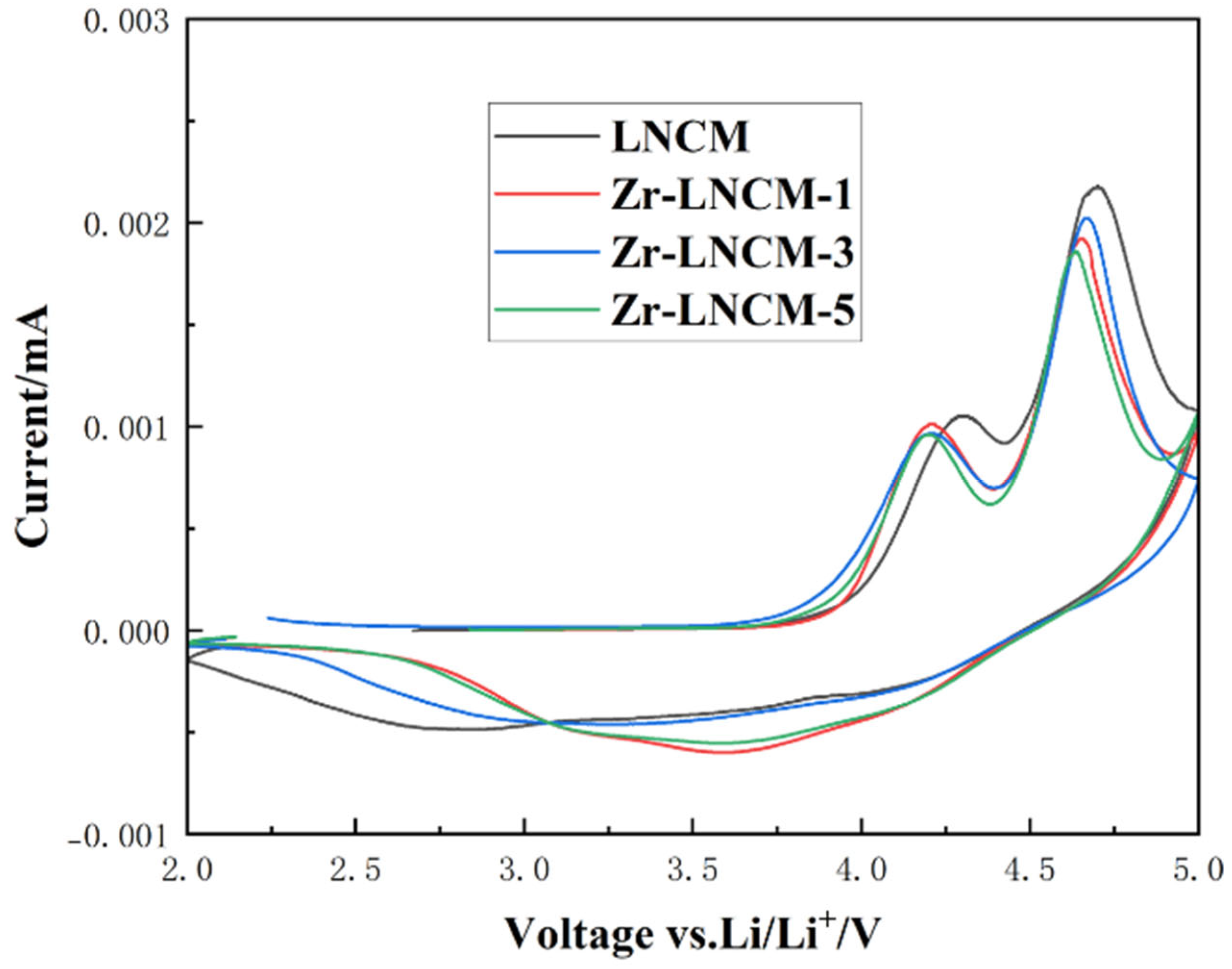
4.3. Cyclic Voltammetric Curve Analysis

To further investigate the reasons behind the enhanced multiplicity performance and cycling stability of the lithium-rich layered material after the application of the Li2ZrO3 coating, cyclic voltammetry (C-V) tests were conducted on four sets of samples within a voltage range of 2 to 5 V at a scanning rate of 0.1 mV/s. Figure 7 presents the cyclic voltammetry curves for the four sample sets. The peaks observed around 4 V during the charging process correspond to the oxidation of transition metals and the extraction of Li+ from LiMO2 [34]. In contrast, the peaks around 4.6 V represent the activation of Li2MnO3, which is accompanied by an irreversible release of O2− and the irreversible detachment of Li+. During the discharge process, the reduction peaks at 3.3 V and 3.8 V correspond to the reduction reactions of Mn4+, Co4+, and Ni4+, respectively [35]. The cyclic voltammetry curves indicate that the peak intensity of the oxidation peak near 4.6 V decreases upon coating with Li2ZrO3. This reduction suggests that the exfoliation of Li2O is suppressed during the activation of the Li2MnO3 phase, thereby improving the initial Coulombic efficiency of the material and enhancing its structural stability. In addition, compared to the uncoated samples, all coated samples showed a left shift in the oxidation peak at around 4.3 V. This may be because after being coated with Li2ZrO3, the coating layer isolated the direct contact between the lithium rich material and the electrolyte, thereby reducing the side reactions between the electrolyte and the material under high voltage, resulting in the oxidation signal peak appearing at lower voltage disturbances. This phenomenon indicates that surface coating with Li2ZrO3 can effectively enhance the stability of the material under high pressure, which is beneficial for improving the overall electrochemical performance of the material. On the other hand, we can also see from the figure that the coated samples Zr-LNCM-1 and Zr-LNCM-3 exhibit two more prominent reduction peaks at 3.3 V and 3.8 V, while the uncoated sample LNCM and the sample Zr-LNCM-5 with a higher coating amount are relatively flat, indicating that the appropriate amount of Li2ZrO3 coating helps the reduction reaction to proceed more fully, making the electrochemical reaction smoother and improving the electrochemical stability of the material.

4.4. AC Impedance Analysis

To further investigate the mechanism by which the Li2ZrO3 coating enhances the material properties, electrochemical impedance tests were conducted on four sets of samples after activation at 0.2 C for 10 cycles. These tests were performed using an electrochemical workstation (CHI760E) with an oscillation amplitude of 5 mV and a frequency range from 0.01 Hz to 105 Hz. The results of the impedance tests are presented in Figure 8. The circuit diagrams utilized for the electrochemical impedance fitting are displayed in the lower right corner, along with the fitting results summarized in a table. As shown in Figure 8a, the electrochemical impedance spectra of the four sample groups consist of semicircles in the mid- and high-frequency regions, along with straight lines in the low-frequency region. Generally, the semicircle observed in the high-frequency region corresponds to the charge-transfer resistance (Rct) at the electrode-electrolyte interface, while the slope of the straight line in the low-frequency region is attributed to the Warburg impedance (Zw). Additionally, the intercept of the semicircle on the x-axis in the high-frequency region represents the conduction impedance (Rs) of Li+ ions across the solid electrolyte interphase (SEI) membrane [36,37]. The Rct values of the coated samples are significantly lower than those of the uncoated samples, indicating that the coated samples exhibit reduced transfer resistance at the interface. In contrast, the Rs values of the four sample groups show a slight increase due to the coating, which may be attributed to the necessity for Li+ ions to traverse the coating layer along with the SEI film. Since the combined Rs and Rct values for the Li2ZrO3 material with 1 wt% coating are lower than those of the uncoated lithium-rich layered material, the samples with 1 wt% coating demonstrate excellent multiplicative performance. To further investigate the Li+ transport rate, the lithium ion diffusion coefficient (DLi+) was calculated using the following equation:
DLi+ = R2T2/2A2n4F4c2σ2
Z′ = σω−1/2
In the above equation, Z′ represents the Warburg impedance, σ represents the Warburg impedance factor, ω represents the angular frequency, R represents the gas constant, T represents the test temperature, A represents the contact area between the electrolyte and the cathode material, n signifies the number of electrons involved in the electrochemical reaction, F is the Faraday constant, and c denotes the lithium ion concentration. [38,39].
The Warburg impedance is represented by the slope of the straight line in the low-frequency region and is associated with the diffusion of Li+ ions within the material [40,41]. Figure 8b illustrates the relationship between Z′ and ω−1/2 for the four sample groups, revealing an inverse correlation between the lithium ion diffusion coefficient and the Warburg impedance factor σ. As shown in Figure 8b, among the four sample groups, those coated with 1 wt% Li2ZrO3 exhibit the highest lithium diffusion coefficients, while the samples coated with 5 wt% Li2ZrO3 demonstrate the lowest Li+ion diffusion coefficient. This reduction may be attributed to an excessive amount of coating material. Figure 8c demonstrates the impedance values of different samples within 0–50 Ω. It can be seen from the figure that the initial impedance values of all samples are basically the same, indicating that the Li2ZrO3 coated does not change the impedance of the material itself. In summary, proper Li2ZrO3 coating can improve the charge transfer capability between the material and the electrolyte, thereby increasing the overall lithium ion migration rate of the material and enhancing the electrochemical performance of the material.

5. Conclusions

By coating Li2ZrO3 material on the surface of Li-rich manganese-based cathode material, the electrochemical performance of the material can be significantly improved. The results show that Li2ZrO3 is successfully coated on the surface of Li-rich manganese-based cathode materials, and this modification method can effectively inhibit the interfacial side reaction between the electrode materials and the electrolyte, inhibit the overgrowth of solid electrolyte interfacial (SEI) film at the interface of the materials, reduce the irreversible release of O2− ions from the materials, and thus improve the first coulombic efficiency of the materials, as well as greatly enhance the cycling stability of the materials. This is of considerable significance for the study of the modification of lithium-rich manganese-based materials.

Author Contributions

Writing—original draft, B.L.; Writing—review & editing, H.W.; Methodology, S.B.; Project administration, W.L.; Data curation, X.W.; Investigation, J.T.; Software, S.S.; Visualization, J.C.; Validation, Y.L.; Supervision, X.T. All authors have read and agreed to the published version of the manuscript.

Funding

This work was financially supported by the National Natural Science Foundation of China (No. 21865021), the Inner Mongolia Key Technology Project (No. 2020GG0166), the Major Science and Technology Project of Hohhot (2023-Winning the leaderboard—High-3), the Fundamental Research Funds for the Inner Mongolia Normal University (No. 2022JBXC025, No. 2022JBZH010, No. 2022JBTD008), Graduate students’ research & Innovation fund of Inner Mongolia Normal University (CXJJS23044), Inner Mongolia Autonomous Region Science and Technology Plan Project (2023YFHH0059).

Data Availability Statement

The data presented in this study are available on request from the corresponding author due to (specify the reason for the restriction).

Acknowledgments

We thank Inner Mongolia Normal University, the National Natural Science Foundation of China and the Inner Mongolia Key Technology Project and other related organisations for their support of this study.

Conflicts of Interest

The authors declare no conflict of interest.

References

  1. Chen, W.M.; Hsieh, H.Y.; Wu, D.Z.; Tang, H.Y.; Chang-Liao, K.S.; Chi, P.W.; Wu, P.M.; Wu, M.K. Advanced TiO2/Al2O3 Bilayer ALD Coatings for Improved Lithium-Rich Layered Oxide Electrodes. ACS Appl. Mater. Interfaces 2024, 16, 13029–13040. [Google Scholar] [CrossRef] [PubMed]
  2. Lu, J.; Wang, Y.; Qiao, Y.; Yang, S.; Cheng, X.; Yang, M.; Zhang, J.; Fu, Z. A high-efficient stable surface-prelithiated Li1.2Ni0.13Co0.13Mn0.54O2 cathode enabled by sacrificial lithium nitrides for high-energy-density lithium-ion batteries. Energy Storage Mater. 2024, 66, 103204. [Google Scholar] [CrossRef]
  3. Zhang, T.; Li, J.T.; Liu, J.; Deng, Y.P.; Wu, Z.G.; Yin, Z.W.; Guo, D.; Huang, L.; Sun, S.G. Suppressing the voltage-fading of layered lithium-rich cathode materials via an aqueous binder for Li-ion batteries. Chem. Commun. 2016, 52, 4683–4686. [Google Scholar] [CrossRef] [PubMed]
  4. Lu, H.; Hou, R.; Chu, S.; Zhou, H.; Guo, S. Progress on modification strategies of layered lithium-rich cathode materials for high energy lithium-ion batteries. Acta Phys. Chim. Sin. 2023, 39, 2211057. [Google Scholar] [CrossRef]
  5. Zhang, R.; Wang, Y.; Fan, J.; Zheng, M.; Dong, Q. The strategy of surface oxygen vacancy stabilization for high-performance lithium-rich cathode materials. J. Electrochem. Soc. 2023, 170, 030517. [Google Scholar] [CrossRef]
  6. Miao, X.W.; Ni, H.; Zhang, H.; Wang, C.G.; Fang, J.H.; Yang, G. Li2ZrO3-coated 0.4Li2MnO3·0.6LiNi1/3Co1/3Mn1/3O2 for high performance cathode material in lithium-ion battery. J. Power Sources 2014, 264, 147–154. [Google Scholar] [CrossRef]
  7. Liu, C.; Wu, M.M.; Zong, Y.H.; Zhang, L.; Yang, Y.; Yang, G. Synthesis and structural properties of xLi2MnO3⋅(1−x)LiNi0.5Mn0.5O2 single crystals towards enhancing reversibility for lithium-ion battery/pouch cells. J. Alloys Compd. 2019, 770, 490–499. [Google Scholar] [CrossRef]
  8. Huang, J.J.; Liu, H.D.; Hu, T.; Meng, Y.S.; Luo, J. Enhancing the electrochemical performance of Li-rich layered oxide Li1.13Ni0.3Mn0.57O2 via WO3 doping and accompanying spontaneous surface phase formation. J. Power Sources 2018, 375, 21–28. [Google Scholar] [CrossRef]
  9. Guo, Z.X.; Ma, T.F.; Xu, T.T.; Chen, Y.; Yang, G.; Li, Y.H. Amorphous Li2ZrO3 nanoparticles coating Li[Li0·17Mn0·58Ni0.25]O2 cathode material for enhanced rate and cyclic performance in lithium ion storage. Mater. Chem. Phys. 2020, 255, 123593. [Google Scholar] [CrossRef]
  10. Paknahad, P.; Abasi, A.A.; Glenn, M.; Ghorbanzadeh, M. Improving the Electrochemical Performance of Lithium-Rich Cathode Materials by Vanadium and Titanium Co-Doping Using Solution Combustion Synthesis. J. Electrochem. Energy Convers. Storage 2023, 20, 011006. [Google Scholar] [CrossRef]
  11. Zhao, B.; Shen, C.; Yan, H.; Xie, J.W.; Liu, X.Y.; Dai, Y.; Zhang, J.J.; Zheng, J.C.; Wu, L.J.; Zhu, Y.M.; et al. Constructing uniform oxygen defect engineering on primary particle level for high-stability lithium-rich cathode materials. Chem. Eng. J. 2023, 465, 142928. [Google Scholar] [CrossRef]
  12. Liu, Y.X.; Qian, K.; He, J.F.; Chu, X.D.; He, Y.B.; Wu, M.Y.; Li, B.H.; Kang, F.Y. In-situ polymerized lithium polyacrylate (PAALi) as dual-functional lithium source for high-performance layered oxide cathodes. Electrochim. Acta 2017, 249, 43–51. [Google Scholar] [CrossRef]
  13. Chen, Q.C.; Luo, L.M.; Wang, L.; Xie, T.F.; Dai, S.C.; Yang, Y.T.; Li, Y.P.; Yuan, M.L. Enhanced electrochemical properties of Y2O3-coated-(lithium-manganese)-rich layered oxides as cathode materials for use in lithium-ion batteries. J. Alloys Compd. 2018, 735, 1778–1786. [Google Scholar] [CrossRef]
  14. Li, H.L.; Zhang, S.C.; Wei, X.; Yang, P.H.; Jian, Z.X.; Meng, J. Glucose-assisted combustion synthesis of Li1.2Ni0.13Co0.13Mn0.54O2 cathode materials with superior electrochemical performance for lithium-ion batteries. RSC Adv. 2016, 6, 79050–79057. [Google Scholar] [CrossRef]
  15. Kapylou, A.; Song, J.H.; Missiul, A.; Ham, D.J.; Kim, D.H.; Moon, S.; Park, J.H. Improved Thermal Stability of Lithium-Rich Layered Oxide by Fluorine Doping. ChemPhysChem 2018, 19, 116–122. [Google Scholar] [CrossRef]
  16. Zhang, Y.P.; Liang, E.Q.; Wang, J.X.; Yu, B.J.; Wang, C.Y.; Li, M.W. Effect of Aluminum Doping on the Stability of Lithium-Rich Layered Oxide Li[Li0.23Ni0.15Mn0.52Al0.10]O2 as Cathode Material. Int. J. Electrochem. Sci. 2017, 12, 9051–9060. [Google Scholar] [CrossRef]
  17. Li, M.; Wang, H.Y.; Zhao, L.M.; Zhou, Y.; Zhang, F.; He, D.N. Improving the electrochemical performance of lithium-rich oxide layer material with Mg and La co-doping. J. Alloys Compd. 2019, 782, 451–460. [Google Scholar] [CrossRef]
  18. Pang, S.L.; Zhu, M.; Xu, K.J.; Wang, Y.G.; Yang, G.M.; Xu, J.; Wu, X.; Li, S.W.; Shen, X.Q.; Xi, X.M. The glucose-based treatment: A green and cost-efficient lithium-rich layered oxide modification strategy. Ceram. Int. 2019, 45, 19268–19274. [Google Scholar] [CrossRef]
  19. Yu, R.Z.; Banis, M.N.; Wang, C.H.; Wu, B.; Huang, Y.; Cao, S.; Li, J.J.; Jamil, S.; Lin, X.T.; Zhao, F.P.; et al. Tailoring bulk Li+ ion diffusion kinetics and surface lattice oxygen activity for high-performance lithium-rich manganese-based layered oxides. Energy Storage Mater. 2021, 37, 509–520. [Google Scholar] [CrossRef]
  20. Zhang, X.P.; Sun, S.W.; Wu, Q.; Wan, N.; Pan, D.; Bai, Y. Improved electrochemical and thermal performances of layered Li[Li0.2Ni0.17Co0.07Mn0.56]O2 via Li2ZrO3 surface modification. J. Power Sources 2015, 282, 378–384. [Google Scholar] [CrossRef]
  21. Chen, C.; Geng, T.F.; Du, C.Y.; Zuo, P.J.; Cheng, X.Q.; Ma, Y.L.; Yin, G.P. Oxygen vacancies in SnO2 surface coating to enhance the activation of layered Li-Rich Li1.2Mn0.54Ni0.13Co0.13O2 cathode material for Li-ion batteries. J. Power Sources 2016, 331, 91–99. [Google Scholar] [CrossRef]
  22. Lu, C.; Wu, H.; Zhang, Y.; Liu, H.; Chen, B.J.; Wu, N.T.; Wang, S. Cerium fluoride coated layered oxide Li1.2Mn0.54Ni0.13Co0.13O2 as cathode materials with improved electrochemical performance for lithium ion batteries. J. Power Sources 2014, 267, 682–691. [Google Scholar] [CrossRef]
  23. Zhao, E.Y.; Liu, X.F.; Zhao, H. Ion conducting Li2SiO3-coated lithium-rich layered oxide exhibiting high rate capability and low polarization. Chem. Commun. 2015, 51, 9093–9096. [Google Scholar] [CrossRef] [PubMed]
  24. Liu, X.P.; Zhao, L.Y.; Li, H.Y. Ga2O3 coated modification and electrochemical performance of Li1.2Mn0.54Ni0.13Co0.13O2 cathode material. Chin. J. Inorg. Chem. 2024, 40, 1105–1113. [Google Scholar]
  25. Zhang, X.Y.; Jiang, W.J.; Mauger, A.; Qilu; Gendron, F.; Julien, C.M. Minimization of the cation mixing in Li1+x(NMC)xO2 as cathode material. J. Power Sources 2009, 195, 1292–1301. [Google Scholar]
  26. Chen, Z.X.; Zhang, Q.J.; Tang, W.J. Ultrahigh Capacity Retention of a Li2ZrO3-Coated Ni-Rich LiNi0.8Co0.1Mn0.1O2 Cathode Material through Covalent Interfacial Engineering. ACS Appl. Mater. 2022, 4, 13785–13795. [Google Scholar] [CrossRef]
  27. Tai, Z.G.; Zhu, W.; Shi, M. Improving electrochemical performances of Lithium-rich oxide by cooperatively doping Cr and coating Li3PO4 as cathode material for Lithium-ion batteries. J. Colloid Interface Sci. 2020, 576, 468–475. [Google Scholar] [CrossRef]
  28. Sun, Y.X.; Zhang, L.J.; Dong, S.D.; Zeng, J.B.; Shen, Y.; Li, X.; Ren, X.F.; Ma, L.X.; Hai, C.X.; Zhou, Y. Improving the electrochemical performances of Li-rich Li1.2Ni0.13Co0.13Mn0.54O2 through cooperative doping of Na+ and Mg2+. Electrochim. Acta. 2022, 414, 140169. [Google Scholar] [CrossRef]
  29. Fang, T.; Zhu, Y.; Hua, J.; Chu, H.; Qiu, S.; Zou, Y.; Xiang, C.; Xu, F.; Sun, L. Enhanced electrochemical properties of sodium-doped lithium-rich manganese-based cathode materials. Mater. Werkst. 2021, 52, 51–59. [Google Scholar] [CrossRef]
  30. Lei, T.X.; Cao, B.; Fu, W.B.; Shi, X.L. A Li-rich layered oxide cathode with remarkable capacity and prolonged cycle life. Chem. Eng. J. 2024, 490, 151522. [Google Scholar] [CrossRef]
  31. Han, J.T.; Zheng, H.F.; Hu, Z.Y.; Luo, X.R.; Ma, Y.T.; Xie, Q.S.; Peng, D.L.; Yue, G.H. Facile synthesis of Li-rich layered oxides with spinel-structure decoration as high-rate cathode for lithium-ion batteries. Electrochim. Acta. 2019, 299, 844–852. [Google Scholar] [CrossRef]
  32. Pechena, L.S.; Makhoninaa, E.V.; Medvedevaa, A.E.; Politova, Y.A.; Rumyantsevb, A.M.; Koshtyal, Y.M. Influence of Tin and Titanium on the Electrochemical Performance of Lithium-Rich Cathode Materials. Inorg. Mater. 2022, 58, 1033–1042. [Google Scholar] [CrossRef]
  33. Boulineau, A.; Simonin, L.; Colin, J.F.; Bourbon, C.; Patoux, S. First evidence of manganese-nickel segregation and densification upon cycling in Li-Rich layered oxides for lithium batteries. Nano Lett. 2013, 13, 3857–3863. [Google Scholar] [CrossRef] [PubMed]
  34. Phattharasupakun, N.; Geng, C.X.; Johnson, M.B.; Väli, R.; Sawangphruk, M.; Dahn, J.R. Impact of Cr Doping on the Voltage Fade of Li-Rich Mn-Rich Li1.11Ni0.33Mn0.56O2 and Li1.2Ni0.2Mn0.6O2 Positive Electrode Materials. Electrochem. Soc. 2020, 16, 7160545. [Google Scholar] [CrossRef]
  35. Zheng, J.M.; Gu, M.; Genc, A.; Xiao, J.; Xu, P.H.; Chen, X.L.; Zhu, Z.H.; Zhao, W.B.; Pullan, L.; Wang, C.M.; et al. Mitigating Voltage Fade in Cathode Materials by Improving the Atomic Level Uniformity of Elemental Distribution. Nano Lett. 2014, 14, 2628–2635. [Google Scholar] [CrossRef]
  36. Tao, S.; Kong, F.J.; Wu, C.Q.; Su, X.Z.; Xiang, T.; Chen, S.M.; Hou, H.H.; Zhang, L.; Fang, Y.; Wang, Z.C.; et al. Nanoscale TiO2 membrane coating spinel LiNi0.5Mn1.5O4 cathode material for advanced lithium-ion batteries. J. Alloys Compd. 2017, 705, 413–419. [Google Scholar] [CrossRef]
  37. Liu, D.M.; Fan, X.J.; Li, Z.H.; Liu, T.; Sun, M.H.; Qian, C.; Lin, M.; Liu, Y.J.; Liang, C.D. A cation/anion co-doped Li1.12Na0.08Ni0.2Mn0.6O1.95F0.05 cathode for lithium ion batteries. Nano Energy 2019, 58, 786–796. [Google Scholar] [CrossRef]
  38. Wang, D.; Huang, Y.; Huo, Z.Q.; Chen, L. Synthesize and electrochemical characterization of Mg-doped Li rich layered Li[Li0.2Ni0.2Mn0.6]O2 cathode material. Electrochim. Acta 2013, 107, 461–466. [Google Scholar] [CrossRef]
  39. Lai, X.W.; Hu, G.R.; Peng, Z.D.; Tong, H.; Lu, Y.; Wang, Y.Z.; Qi, X.Y.; Xue, Z.C.; Huang, Y.; Du, K. Surface structure decoration of high capacity Li1.2Mn0.54Ni0.13Co0.13O2 cathode by mixed conductive coating of Li1.4Al0.4Ti1.6(PO4)3 and polyaniline for lithium-ion batteries. J. Power Sources 2019, 431, 144–152. [Google Scholar]
  40. Li, J.H.; Liu, Z.Q.; Wang, Y.F.; Wang, R.G. Investigation of facial B2O3 surface modification effect on the cycling stability and high-rate capacity of LiNi1/3Co1/3Mn1/3O2 cathode. J. Alloys Compd. 2020, 834, 155150. [Google Scholar] [CrossRef]
  41. Liu, Y.J.; Liu, D.M.; Wu, H.H.; Fan, X.J.; Dou, A.C.; Zhang, Q.B.; Su, M.R. Improved Cycling Stability of Na-Doped Cathode Materials Li1.2Ni0.2Mn0.6O2 via a Facile Synthesis. ACS Sustain. Chem. Eng. 2018, 6, 13045–13055. [Google Scholar] [CrossRef]
Figure 1. XRD schematics of samples coated with different amounts of Li2ZrO3.
Crystals 15 00262 g001
Figure 2. (a,c,e,g) Scanning electron microscope images of LNCM, Zr-LNCM-1, Zr-LNCM-3, and Zr-LNCM-5 at 10,000×; (b,d,f,h) Scanning electron microscope images of LNCM, Zr-LNCM-1, Zr-LNCM-3, and Zr-LNCM-5 at 50,000×, respectively.
Crystals 15 00262 g002
Figure 3. (a,b) show the EDS maps of LNCM, Zr-LNCM-1, respectively.
Crystals 15 00262 g003
Figure 4. (ad) TEM images of LNCM, Zr-LNCM-1, Zr-LNCM-3, and Zr-LNCM-5, respectively, and (e,f) HRTEM images of LNCM, Zr-LNCM-1, respectively.
Crystals 15 00262 g004
Figure 5. (a) Initial charge/discharge and Coulombic efficiency of Li2ZrO3 coated with different amounts of Li2ZrQ3, (b) Charge/discharge curves after 500 cycles of different materials.
Crystals 15 00262 g005
Figure 6. Rate performance before and after coating.
Crystals 15 00262 g006
Figure 7. Cyclic voltammogram of the material before and after coating.
Crystals 15 00262 g007
Figure 8. (a) Electrochemical impedance initial plot of the pristine sample with different amounts of Li2ZrO3 coating, (b) Plot of the relationship between Z′and ω−1/2, (c) EIS impedance mapping between the initial 0–50 Z (ohms).
Crystals 15 00262 g008
Table 1. Cell information after structural refinement of four groups of samples.
SampleLattice
R-3mC2/m
a [nm]c [nm]V [nm]a [nm]b [nm] c [nm]V [nm]Rwp [%]CHI2
LNCM0.28431.41990.09940.49190.85070.50520.19936.051.75
Zr-LNCM-10.28461.42120.09970.49210.85220.50360.19915.991.71
Zr-LNCM-30.28451.42140.09960.49310.85310.50150.19906.071.81
Zr-LNCM-50.28451.42160.09970.49310.85380.5020.19936.192.10
Table 2. I(003)/I(104) vs. c/a for four groups of samples.
SampleI(003)/I(104)a [nm]c [nm]c/a
LNCM1.8080.28431.41994.994
Zr-LNCM-11.9370.28461.42124.994
Zr-LNCM-31.8290.28451.42144.996
Zr-LNCM-51.9020.28451.42164.996
Table 3. Initial charge/discharge data of samples before and after coating.
SampleInitial Charge Specific Capacity [mAh·g−1]Initial Discharge Specific Capacity [mAh·g−1]Irreversible Specific Capacity [mAh·g−1]Initial Charge and Discharge Efficiency [%]
LNCM280.1159.6120.556.9
Zr-LNCM-1269.4169.999.563
Zr-LNCM-3259.5165.693.963.8
Zr-LNCM-5251.8154.897.061.4
Table 4. Changes in some electrochemical properties before and after coating of four materials.
Coating MaterialFirst Coulombic Efficiency Change (Before and After Coating)Capacity Retention (Cycle Number)Initial Discharge Specific Capacity Change [mAh·g−1]
Li2ZrO3+6.1%60% (500 times)+10.3
SnO2 [21]+0%88% (200 times)+38.2
Li2SiO3 [23]/75% (100 times)−2.5
Ga2O3 [24]+2.3%85.6% (200 times) +7.4
Disclaimer/Publisher’s Note: The statements, opinions and data contained in all publications are solely those of the individual author(s) and contributor(s) and not of MDPI and/or the editor(s). MDPI and/or the editor(s) disclaim responsibility for any injury to people or property resulting from any ideas, methods, instructions or products referred to in the content.

