Article

A Study of the Effects of Mechanical Alloying Fraction, Solution Treatment Temperature and Pre-Straining Degree on the Structure and Properties of a Powder Metallurgy-Produced FeMnSiCrNi Shape Memory Alloy

1
Faculty of Materials Science and Engineering, “Gheorghe Asachi” Technical University of Iași, Blvd. Dimitrie Mangeron 71A, 700050 Iași, Romania
2
Yurtbay Seramik, Research & Development Center, Inonu, 26670 Eskisehir, Turkey
*
Author to whom correspondence should be addressed.
Crystals 2025, 15(2), 105; https://doi.org/10.3390/cryst15020105
Submission received: 30 December 2024 / Revised: 19 January 2025 / Accepted: 20 January 2025 / Published: 21 January 2025
(This article belongs to the Special Issue Advances in Multifunctional Materials and Structures)

Abstract

:
A shape memory alloy with the chemical composition Fe-14Mn-6Si-9Cr-5Ni (mass %) was produced by powder metallurgy (PM) from as-blended powders mixed with mechanically alloyed (MA’ed) powder volumes in amounts of 0, 10 and 20. After powder blending, pressing and sintering, the specimens were hot-rolled, spark erosion cut with different configurations and solution-treated between 700 and 1100 °C. After metallographic preparation, structural analyses were performed by X-ray diffraction and microscopic observation performed by optical and scanning electron microscopy (SEM). The analyses revealed the presence of thermal- and stress-induced martensites caused by solution treatment and pre-straining. Due to the relatively low Mn amount, significant quantities of α′ body center cubic martensite were formed during post-solution treatment water cooling. Solution-treated lamellar specimens underwent a training thermomechanical treatment comprising repeated cycles of room temperature bending, heating and sputtered water cooling. By cinematographic analysis, the occurrence of the shape memory effect (SME) was revealed, in spite of the large amount of α′ bcc martensite. Tensile specimens were subjected to room temperature failure tests and pre-straining (up to 4% permanent strain, after loading–unloading). After tensile pre-straining, a diminution of α′ martensite amount was noticed on XRD patterns, which was associated with the formation of internal sub-bands in the substructure of martensite and were observed by high-resolution SEM. These results prove that SME can be obtained in trained PM_MA’ed Fe-14Mn-6Si-9Cr-5Ni specimens in spite of the large amount of thermally induced α′ bcc martensite, the stress-induced formation of which is impeded by the presence of internal sub-bands.

1. Introduction

Shape memory alloys (SMAs) based on the Fe-Mn-Si system have been studied extensively since their discovery in the 1980s [1]. The shape memory effect (SME) in these alloys relies on the stress-induced formation of ε (hexagonal close-packed, hcp.) martensite from γ (face-centered cubic, fcc) austenite, and its subsequent thermally induced reversion [2]. Besides ε (hcp.) martensite, α′ (body-centered cubic, bcc) martensite is typically observed in the microstructure of this alloy system, with low Mn amounts, when deformed at high deformation degrees, being mostly present at the intersection of ε—hcp martensite plates. Most of the reports from the literature consider that α′ (bcc) martensite, diminishes the amount of SMEs [3].
To improve corrosion resistance, elements such as Cr and Ni were added, leading to the development of commercial grades such as Fe-28Mn-6Si-5Cr [4] and Fe-14Mn-6Si-9Cr-5Ni [5]. Mass is denoted by % in all the chemical compositions given hereinafter.
The formation of stress-induced martensite, which plays a crucial role in shape memory behavior, can be influenced by various factors such as alloy composition, processing route, and heat treatment [6].
Traditionally, these alloys were produced through ingot metallurgy, involving casting, remelting, and prolonged heat treatments [7]. However, powder metallurgy (PM) has emerged as an alternative processing route that offers better control over composition and microstructure [8].
When combined with mechanical alloying (MA), PM has the potential to enhance the further refinement of grain size, reduce the homogenization time [9] and improve the mechanical properties [10] and shape memory performance of Fe-Mn-Si based alloys as compared to ingot metallurgy [11].
Within previous investigations on a PM Fe-14Mn-6Si-9Cr-5Ni SMA, the presence of both ε—hcp. and α′—bcc martensites was reported [12], and increasing tendencies of the amount of the latter were observed with the increase in both heat treatment temperature [13] and MA fraction [14], exceeding 50% of the microstructure [15]. In spite of the presence of a large amount of α′—bcc martensite, free-recovery shape memory effect was emphasized after thermomechanical training [16].
The present paper aims to investigate the cumulated effect of mechanical alloying, heat treatment temperature and tensile pre-straining on the structure and properties of PM Fe-14Mn-6Si-9Cr-5Ni SMA. Special attention will be given to the evolution of thermally induced α′—bcc martensite caused by tensile pre-straining. The presence of free-recovery SME and its evolution during training will be investigated in the specimens containing the largest amount of thermally induced α′—bcc martensite.

2. Materials and Methods

Three batches of elemental powders, with the nominal chemical composition 66Fe-l4Mn-6Si-9Cr-5Ni selected for this study, were mixed in a polymeric jar using a Turbula blender (Glen MillsTM, T2C, Clifton, NJ, USA) for 30 min to obtain a homogeneous powder mixture under a solid-state mixing condition [17]. The first batch was kept in an as-blended state. At the same time, different powder amounts were mechanically alloyed in a high-energy ball mill (SPEXTM D8000, MedicalExpo, Marseilles, France), under an argon atmosphere, using stainless steel vials and stainless-steel milling balls, using a ball-to-powder-ratio of 1/10. As previously pointed out by some of the present authors, the optimum MA time was 4 h, after which the agglomeration tendency of the powders was increased [17]. Within the present experiments, the second batch had 10 vol. % mechanically alloyed (MA’ed) powder and the third had 20 vol. %. In this way, three individual types of composite powders were obtained, with 0, 10 and 20 vol. % MA’ed) powder, designated as 0_MA, 10_MA and 20_MA, respectively [18].
The three powder compounds were pressed at 500 MPa in rectangular prism molds, with a hydraulic press, and sintered (1150 °C/2 h under Ar) with oxide reduction with hydrogen (800 °C/30 min) [19].
The systematic measurement of the chemical composition was performed on powders and specimen cross-sections. The former was achieved by EDS analysis at multiple points of the samples [18]. The latter was performed on metallographic cross-sections of the specimens, embedded in cold mounting resin and obtained by grinding, polishing and etching. The measurements were performed with a VEGA II LMH TESCAN scanning electron microscope (Warrendale, PA, USA) (described below) equipped with an EDX-QUANTAX QX2 ROENEC energy dispersive spectrometer and ESPRIT 1.8 software (Bruker, Billerica, MA, USA). The results, determined by 20 systematic measurements performed on the same region with martensite plates, revealed standard deviations ranging between 0.12 at% for Mn and 0.39 at % for Ni [20].
Further densification of the sintered powder compacts was accomplished by hot rolling at 1100 °C, comprising a rapid reinsertion (during max. 3 s) of rolled specimens into the heating furnace after each rolling pass.
The apparent density [21] of the samples was precisely determined by weighing them using an electronic balance. In this way, the porosity levels decreased in the order of 16.85% (0_MA), 8.03% (10_MA) and 5.94% (20_MA) while specimen thickness was reduced from 4 mm to approx. 1 mm [22].
Hot rolled specimens were further subjected to a solution treatment (ST), being held for 5 min at five different temperatures, 700, 800, etc., until 1100 °C and finally water quenched. Each of the fifteen specimens will be further designated with its MA fraction and ST time (e.g., 10_MA_1100 represents the specimen with 10 vol. % MA’ed powders, solution-treated at 1100 °C).
Two types of specimens were cut by spark erosion from homogenized samples: (i) “dog bone” with gauge dimensions 1 mm × 4 mm × 20 mm for tensile pre-straining and failure tests, and rectangular specimens (1 mm × 4 mm × 100 mm) for microscopic observations and shape memory tests. To remove the superficial oxidized and demagnetized layers, the specimens were ground under water cooling.
Tensile pre-straining and failure tests were performed at RT using an INSTRON 3382 tensile machine (Norwood, MA, USA) and a cross-head speed of 1 mm/min. The relative elongation of the specimens was determined by the machine’s software (Blue Hill, v.2, Instron, Norwood, MA, USA), based on total elongation. All the machine’s features were detailed in a previous report [23].
After pre-straining, the gauges of tensile specimens were cut and subjected to metallographic preparation for microscopic observations and X-ray diffraction (XRD) analyses. The same treatment was applied to both pre-strained gauges (4 mm × 20 mm) and rectangular specimens (4 mm × 25 mm). It consisted of: (i) embedding into Mécaprex KM-U (PRESI, Eybens, France) bicomponent cold mounting resin (not to alter the thermodynamic history); (ii) grinding (down to 5 μm grit size) and (iii) automatic polishing (with a colloidal SiO2 suspension with 0.02 μm particle size) under a water stream, using a METKON FORCIPOL 1 V machine (Bursa, Turkey). For the etching of polished specimens belonging to an FeMnSi-based system, a solution of 1.2% K2S2O5 + 1%NH4HF2 in 100 mL distilled water is currently used [24]. Since the etchant destroyed the protective outer oxide layer, the corroded surfaces had to be neutralized for 1 h into a solution of ammonium pentaborate to protect the objective lens of the optical microscope against ammonium bifluoride [25].
XRD diagrams (diffractograms) were recorded at a diffraction interval of 40–100° of the 2θ angle, using a Bruker ASX D8 Advance (Bruker, Billerica, MA, USA) diffractometer with Cu K radiation. Three Joint Committee on Powder Diffraction Standards (JCPDS) files, 01-071-8285, 00-034-0396 and 01-071-8288, were used for identification of the metallographic phases ε—hcp, α′—bcc and γ—fcc, respectively.
Optical microscopy (OM) observations were performed with an OPTIKA XDS-3 MET device equipped with an OPTIKAM4083.B5 digital USB camera (Optika Microscopes Italy, Ponteranica, Italy).
Scanning electron microscopy (SEM) micrographs were recorded with different magnifications. For low magnifications, a common device, VEGA II LSH TESCAN (TESCAN, Brno—Kohoutovice, Czech Republic) was used. For nanostructural observations, a high-resolution device (HR-SEM) Neon 40 Esb Scanning Electron Microscope (Carl Zeiss NTS, Oberkochen, Germany) was employed. Its parameters include a resolution of 1.1 ÷ 2.5 nm at a voltage U = 20 ± 1 kV.
Rectangular specimens were trained to develop a free-recovery shape memory effect (FR-SME). For this purpose, the martensitic specimens were bent against cylindrical caliber, being rigidly fixed at one end while the motion of the other end, under increasing temperature, was detected by video control. Heating was applied with a mobile flame burner, being focused on the most deformed area of the specimen, with the aim of exceeding the critical temperature of reverse martensitic transformation to develop free-recovery SME.
Therefore, each training cycle comprised room temperature (RT) bending, heating and RT-sputtered water cooling [26]. During each training cycle, the displacement of free specimens, as a function of temperature, was recorded in each by an acquisition module and investigated by cinematographic analysis [27].

3. Results and Discussion

Using the abovementioned experimental techniques, the effects of MA and ST temperature will be analyzed from the point of view of microstructural changes, as well as tensile and shape memory behavior. After evaluating the stress variation with strain, during tensile loading–unloading, the microstructural changes caused by pre-straining will be investigated.

3.1. Mechanical Alloying and Solution Treatment Effects

The effects of replacing different amounts of powders which were blended and mechanically alloyed (MA’ed) and those of different ST temperatures are illustrated in Figure 1 by the corresponding XRD patterns. According to the data from JCPDS files, 00-034-0396, 01-071-8285 and 01-071-8288, the crystallographic maxima of the three previously mentioned phases were identified. Table S1, from the Supplementary Materials summarizes the values of 2θ angle.
The three phases have the crystallographic parameters of aα′ = 0.287 nm; aε = 0.254 nm, cε = 0.4 nm and aγ = 0.36 nm, respectively [28,29].
Considering that most of the diffraction maxima, within the significant region of 2θ, are overlapping, the accurate determination by qualitative analysis of the amounts of the three phases is rather difficult. In addition, any tentative quantitative analysis exclusively using the non-overlapping diffraction maxima could result in huge fluctuations in the phase amounts, leading to the misleading conclusion that the samples are inhomogeneous.
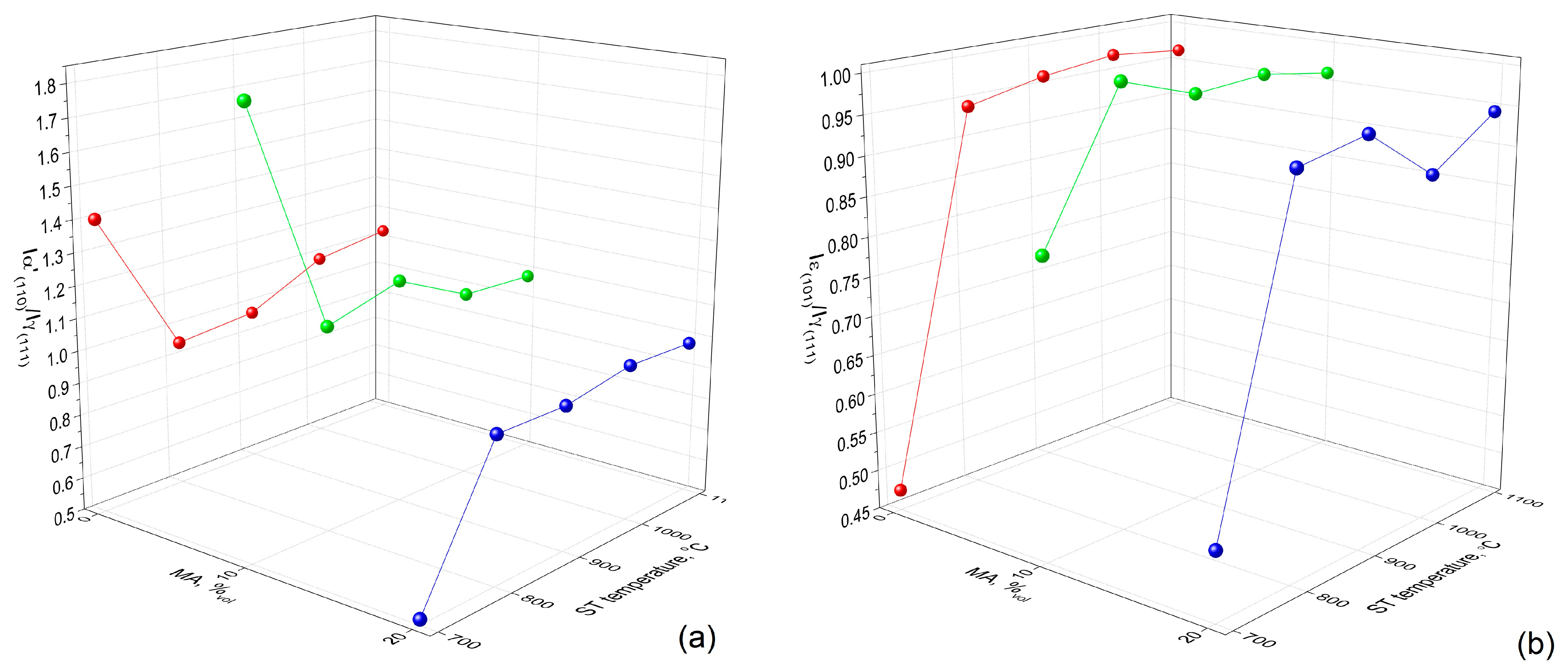
Therefore, for performing a relative semi-quantitative evaluation of the two martensitic phases, a previously applied approach for the XRD study of Fe-Mn based alloys was used [30]. The method consists of considering only the ratios between the intensities of α′(110)/γ(200) and of ε(101)/γ(200). In this way, the evolution tendencies of the two martensitic phases with regard to austenite can be compared. The results are illustrated in Figure 2.
It is noticeable that the specimens ST’ed at 700 °C do not fit to the general evolution tendencies. Disregarding the data given by these specimens, one can observe that, as compared to austenite, the relative amount of α′—bcc martensite experienced a slightly increasing tendency with the increase in ST temperature. This tendency is sustained by the increase in Figure 1 of the relative intensity of the main α′—bcc maximum, (110)α′ for each MA fraction, separately.
By comparing Figure 2a and Figure 2b, it can be observed that, with very few exceptions, the fractions of α′—bcc martensite are larger than those of ε—hcp martensite. This imbalance might suggest the hindrance of any SME occurrence.
During the heating stage of the solution treatment, it has been observed that ε—hcp martensite partially recovered to γ—fcc austenite and partially changed into α′—bcc martensite, which formed as a result of the Shockley partial dislocations generated during γ → ε → α′ transformation. This α′—bcc martensite might be a barrier to shape recovery during the reverse martensitic transformation [31].
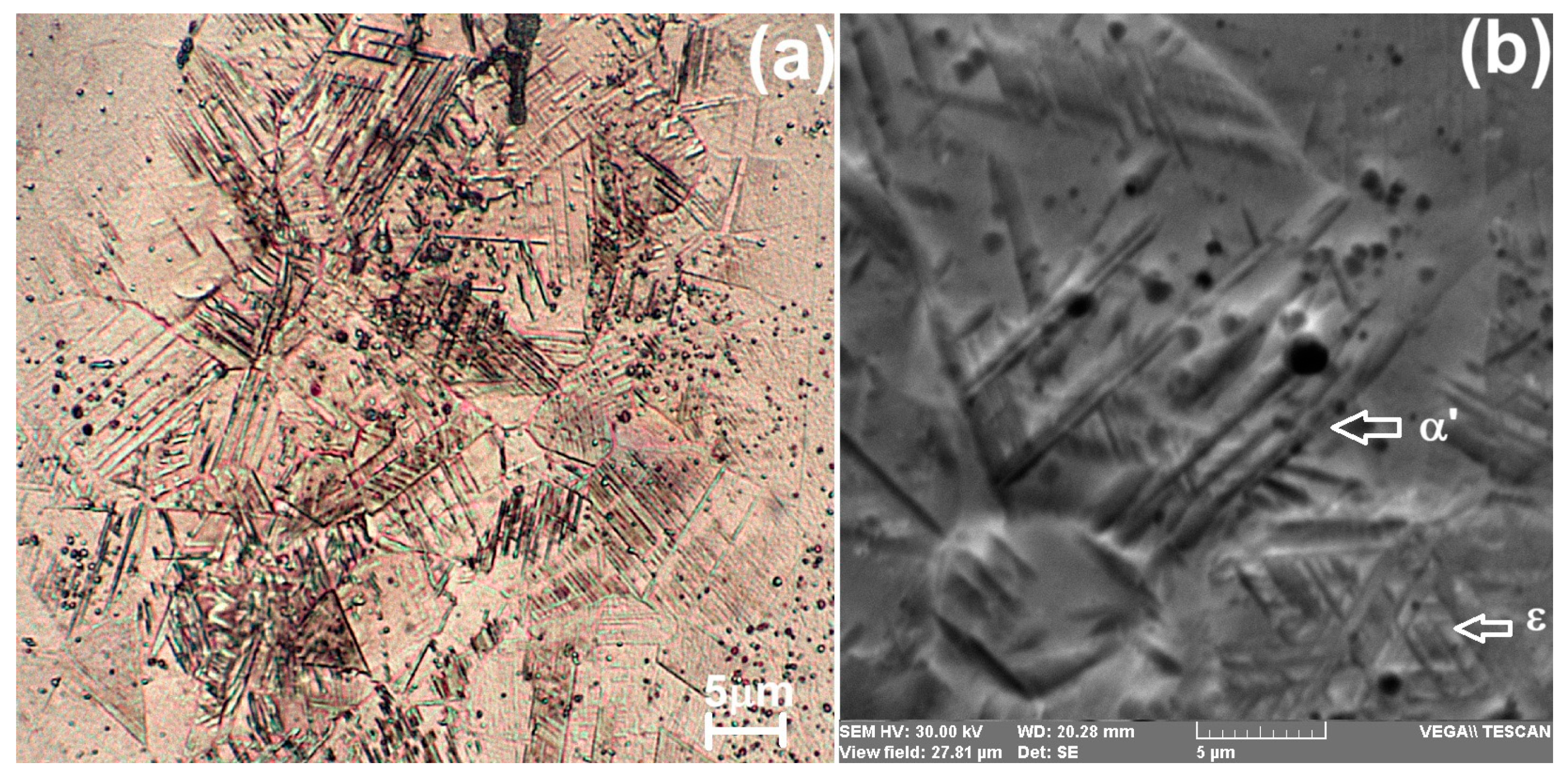
Aiming to reveal the morphological features of the two types of martensite, OM and SEM micrographs were recorded. One example is given in Figure 3 for the specimen 20_MA_1000, which presented the largest amount of α′—bcc martensite.
Due to the crystallographic compatibility between fcc and hcp unit cells, ε martensite only distorts the austenitic matrix to a small extent and its plates are long and narrow, with a typical ‘‘triangular’’ morphology, as noticeable in the lower-right corner of Figure 3b. Conversely, the formation of α′—bcc martensite causes a larger distortion accompanied by a volume change in the austenitic matrix, and martensite forms as short lenticular-shaped bands with deeper surface relief [32], being preferably nucleated in the intersection volume of various habit planes of ε—hcp martensite plate variants [33].
The following experiments aimed to demonstrate the possibility of developing SME even in the presence of a substantial initial amount of α′—bcc martensite, such as in the case of rectangular 20_MA_1000 specimens. For this purpose, cinematographic analysis was used.
The thermomechanical training procedure comprised RT bending–heating-sputtered water cooling. Before training, the edges were polished to avoid cracks nucleation.
Due to the increased brittleness caused by the large amount of α′—bcc martensite, the first bending was performed with great care, so as not to cause cracks in the specimen. One example of the evolution of the displacement of specimen’s free end during heating is illustrated in Figure 4a.
During heating from 26 °C to 294 °C, the specimen’s free end rose 10 mm, with a displacement rate of 1.16 mm/s. In the second cycle, the vertical displacement increased to 15 mm. In the third and fourth cycles, the training effect of Fe-Mn-Si-based SMAs [34] became obvious and the specimen softened, which enabled the increase in the vertical displacement to 20 and 22 mm, with a concomitant increase in displacement rate to 1.64 and 2 mm/s, respectively. Therefore, after each subsequent training cycle, both the specimen’s free-end displacement and the displacement rate increased.
Figure 4b displays the variation in the free end of the specimen with temperature, in the fifth cycle of thermomechanical training. At this point, one might argue that the temperature was not evenly distributed in the sample and its value was only locally measured. On the other hand, one should note that the experiment was only meant to reveal the possibility of a PM–MA’ed Fe-Mn-SiCr-Ni specimen to develop free-recovery SME and to improve it by training in spite of the fact that the amount of α′—bcc martensite was larger than that of ε—hcp martensite. Similar results, obtained on different specimens but under similar experimental conditions, were previously reported by some of the present authors [8,16]. It is obvious that the specimen’s free-end displacement exceeded 23 mm.
These results prove that, despite the large amount of α′—bcc martensite, specimen 20_MA_1000 was able to develop free-recovery SME, as an effect of thermomechanical training. This conclusion contradicts the general opinion that α′—bcc martensite hinders the reversibility of martensitic transformation [35].
Considering the massive presence of the α′—bcc martensitic phase, tensile failure tests were performed in an attempt to correlate the structure with tensile behavior. The representative stress–strain curves are illustrated in Figure 5.
All the fifteen tested specimens failed at relative elongations ranging between 2 and 4%. The ultimate tensile failure stress varied between 250 and 650 MPa, the largest stresses being generally obtained at the specimens that contained the largest amounts of α′—bcc martensite. Since all fifteen specimens contained α′—bcc martensite, which does not possess close-packed planes, the stress–strain curves did not experience any necking, and their tensile behavior can be defined as brittle. In addition, one should consider that, unlike slip-induced plasticity which causes an initial linear Hookean part, transformation-induced plasticity, associated with the transformation of stress-induced martensite, does not have any linear portion [36]. For this reason, the slope of the initial part may not always correspond to Young’s modulus values. Therefore, the parts of the strain diagram below the yield stress are not linear and their slope does not represent the Young’s modulus of elasticity.
However, no direct quantitative correlation could be found between the presence of the bcc phase, without close-packed planes able to form slip systems, and the evolution tendencies of the values of ultimate strains and stresses.

3.2. Tensile Pre-Straining Effects

Considering the tensile failure curves from Figure 5, several specimens of the fifteen types were subjected to tensile loading–unloading, up to various maximum strains, and the permanent strains were recorded after unloading for each specimen in part. Then, the pre-strained gauges were cut, metallographically prepared and analyzed by XRD and SEM.
The XRD patterns are shown in Figure 6. It is noticeable that some of the specimens failed and could not be pre-strained up to closer values to the ultimate strains. The permanent strain, recorded after loading–unloading, is marked above each corresponding XRD pattern. Table 1 displays the values of the amounts of the two martensitic phases, determined by relative semi-quantitative evaluation.
At several specimens, such as 0_MA_900, 0_MA_1000, 0_MA_1100, 20_MA_1000 or 20_MA_1100, which contained, in their initial state, larger amounts of α′—bcc martensite as compared to austenite amounts, respectively, pre-straining caused a marked reduction in the amount of this type of martensite.
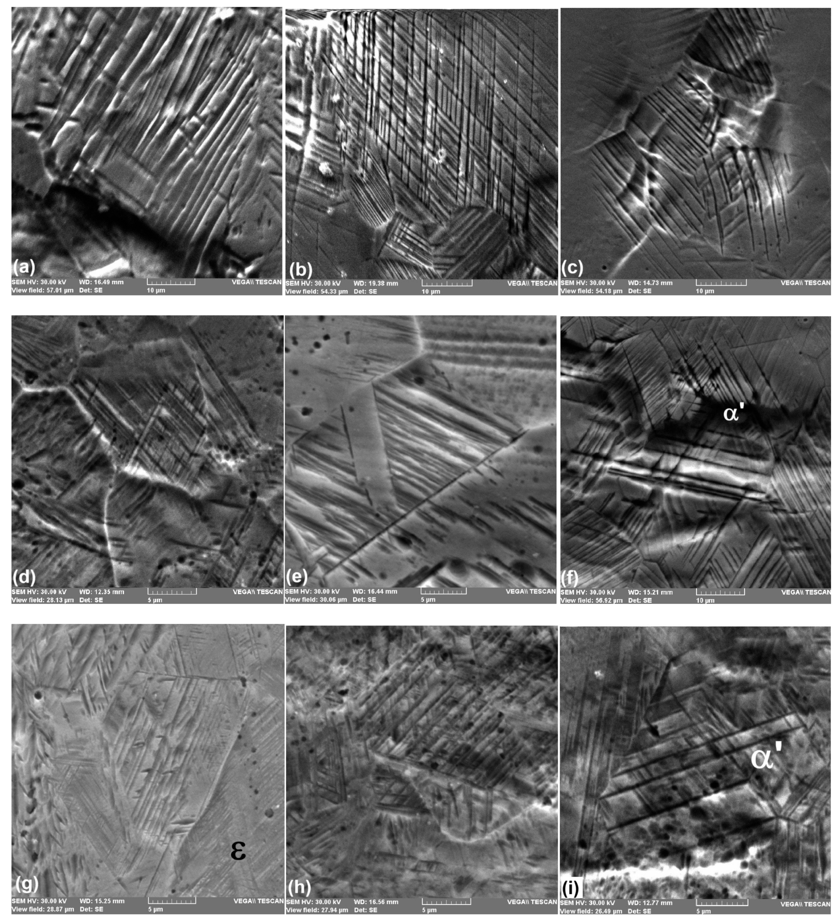
Aiming to highlight the morphological changes caused by pre-straining, SEM micrographs were performed. The typical examples are shown in Figure 7.
Each microstructure presents limited regions of fine short ε—hcp martensite plates and wide regions with wide bands with marked surface relief, typically associated with α′—bcc martensite, at Fe-Mn-Si-based SMAs [37]. The relative amount of α′—bcc martensite decreased after pre-straining, in comparison with the amount of thermally induced martensite determined after solution treatment [38].
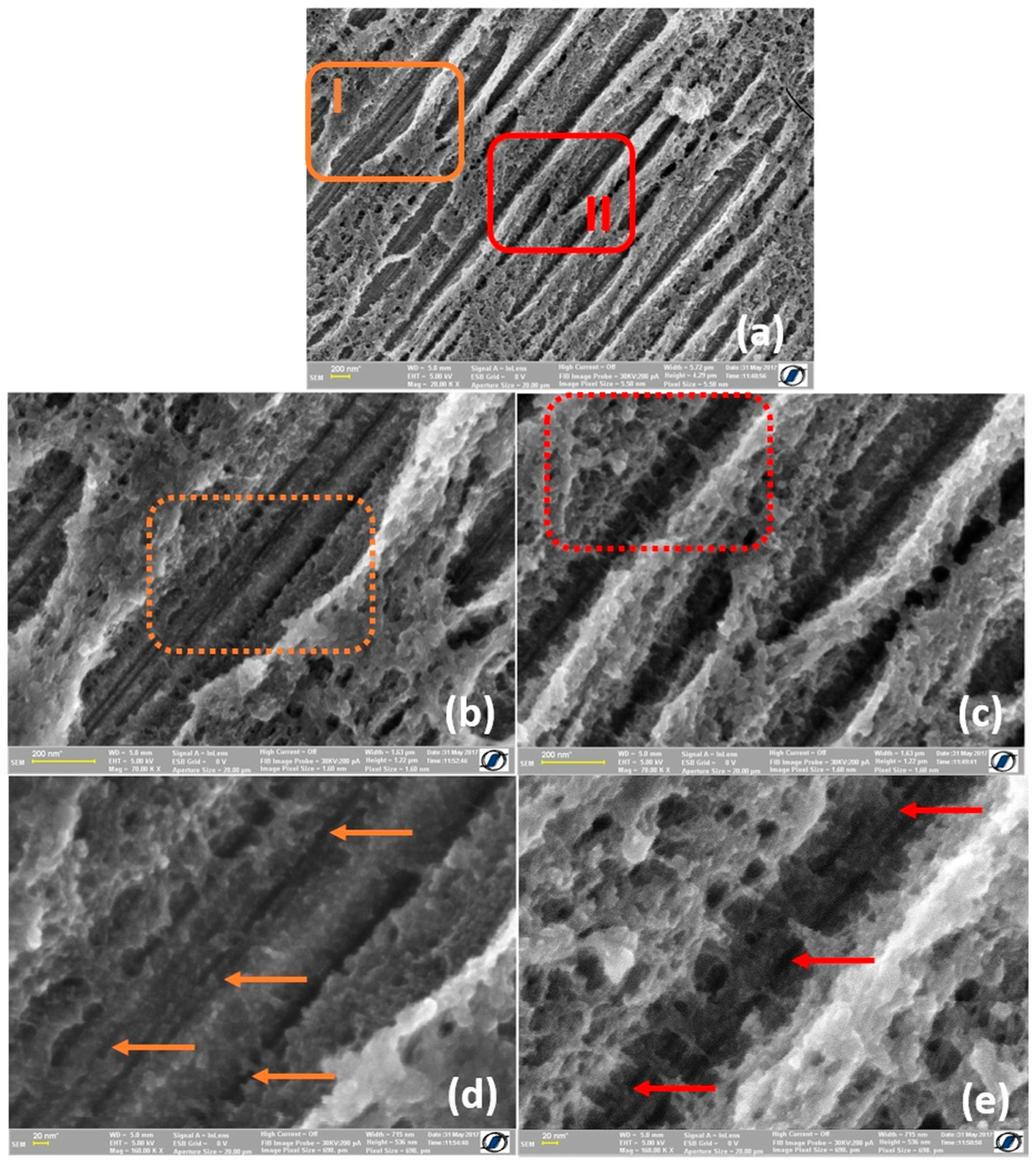
In an attempt to determine the causes of this unusual behavior, HR-SEM observations were performed on specimen 0_MA_1100. This specimen was ST’ed at 1100 °C, a temperature that was meant to transform any residual martensitic phase into the austenitic phase [39]. However, in the present case, the specimen contained a large relative amount of α′—bcc thermally induced martensite that decreased after pre-straining with 3.8%. Some representative HR-SEM micrographs are shown in Figure 8.
While increasing the micrographs’ magnification, a series of parallel sub-bands became noticeable in the sub-structure of the martensite plates. Since no deformation was applied to this specimen, these dark stripes cannot represent Lüders-like slip bands [40]. Moreover, the occurrence of slip bands is rather improbable due to the bcc structure of α′ martensite, which does not possess close-packed planes that are prone to form slip systems.
The average width of the sub-bands was 20 nm, which is about one-fifth of that of ε—hcp martensite plates. It is possible that these sub-bands, which are present in the structure of α′—bcc thermally induced martensite, impede the growth of stress-induced martensite during pre-straining.

4. Summary and Conclusions

Summarizing the above results and discussion, a few conclusions can be drawn concerning the influence of MA volume fraction and ST temperature on the structure and properties of an Fe-14Mn-6Si-9Cr-5Ni PM SMA:
  • The amount of α′—bcc martensite experienced an increasing tendency, which was observed in the evolution of the ratio of the relative intensities of α′(110)/γ(200) being favored by the rise in MA volume fraction and ST temperature;
  • α′—bcc martensite plates were short lenticular-shaped, with deep surface relief;
  • Despite the amount of α′—bcc martensite, which was larger than that of ε—hcp martensite, the specimens could develop free-recovery SME;
  • During thermomechanical training, increases in both the recoverable deformation and the displacement rate of specimens’ free end were observed;
  • After training, the free end’s displacement exceeded 23 mm, and its rate reached 2 mm/s;
  • Due to the large amount of α′—bcc thermally induced martensite, the specimens were brittle and failed at tensile strains between 2 and 4% and ultimate stress between 250 and 650 MPa;
  • The evolution in the specimens’ three-phase structure, observed by XRD, caused variations in yield strength and Young’s modulus, as well as total and permanent relative elongations;
  • No direct quantitative correlation could be found between the fraction of the bcc phase and the evolution tendencies of the tensile ultimate strains and stresses.
As an effect of pre-straining, consisting of tensile loading–unloading, the following changes were observed:
  • Regardless of the MA volume fraction, ST temperature and pre-straining degree, the evolution of the relative intensities of α′(110)/γ(200) and ε(101)/γ(200) suggested that the amount of α′—bcc martensite was larger than that of ε—hcp martensite;
  • Based on the evolution of the relative intensity of α′(110)/γ(200), with the increase in the pre-straining degree, it can be concluded that the total amount of α′—bcc martensite had a decreasing tendency after pre-straining, compared to the amount of thermally induced martensite determined after solution treatment;
  • The internal sub-bands observed by HR-SEM in the nanostructure of α′—bcc thermally induced martensite have the potential to impede the growth of stress-induced martensite during pre-straining.
These results emphasize the potential of PM-MA’ed Fe-14Mn-6Si-9Cr-5Ni SMA to be used for the manufacturing of the active parts of low-cost temperature-controlled actuators able to develop fast motion during heating.

Supplementary Materials

The following supporting information can be downloaded at: https://www.mdpi.com/article/10.3390/cryst15020105/s1, Table S1.

Author Contributions

Conceptualization, E.M. and L.-G.B.; methodology, N.-M.L.; software, M.P.; validation, E.M., B.O. and L.-G.B.; formal analysis, N.C.; investigation, E.M. and N.C.; resources, G.B.; data curation, B.P.; writing—original draft preparation, G.B.; writing—review and editing, N.-M.L.; visualization, M.P.; supervision, B.P.; project administration, B.O.; funding acquisition, L.-G.B. All authors have read and agreed to the published version of the manuscript.

Funding

This research received no external funding.

Data Availability Statement

Data are contained within the article.

Acknowledgments

The authors acknowledge the expertise and support of R.I. Comăneci in performing the tensile tests.

Conflicts of Interest

The authors declare no conflicts of interest.

References

  1. Sato, A.; Chishima, E.; Soma, K.; Mori, T. Shape memory effect in γ⇄ɛ transformation in Fe-30Mn-1Si alloy single crystals. Acta Metall. 1982, 30, 1177–1183. [Google Scholar] [CrossRef]
  2. Maki, T. Ferrous shape memory alloys. In Shape Memory Materials; Otsuka, K., Wayman, C.M., Eds.; University Press: Cambridge, UK, 1998; pp. 117–132. [Google Scholar]
  3. Arruda, G.J.; Buono, V.T.L.; Andrade, M.S. The influence of deformation on the microstructure and transformation temperatures of Fe–Mn–Si–Cr–Ni shape memory alloys. Mater. Sci. Eng. A 1999, 273–275, 528–532. [Google Scholar] [CrossRef]
  4. Otsuka, H.; Yamada, H.; Maruyama, T.; Tanahashi, H.; Matsuda, S.; Murakami, M. Effects of alloying additions on Fe-Mn-Si shape memory alloys. ISIJ Int. 1990, 30, 675–679. [Google Scholar] [CrossRef]
  5. Moriya, Y.; Kimura, H.; Ishizaki, S.; Hashizume, S.; Suzuki, S.; Suzuki, H.; Sampei, T. Properties of Fe-Cr-Ni-Mn-Si (-Co) shape memory alloys. J. Phys. IV 1991, 4, 433–437. [Google Scholar] [CrossRef]
  6. Kajiwara, S. Characteristic features of shape memory effect and related transformation behavior in Fe-based alloys. Mater. Sci. Eng. A 1999, 273–275, 67–88. [Google Scholar] [CrossRef]
  7. Berns, H.; Theisen, W. Ferrous Materials: Steel and Cast Iron; Springer: Berlin/Heidelberg, Germany, 2008; pp. 190–207. [Google Scholar] [CrossRef]
  8. Pricop, B.; Soyler, A.U.; Ozkal, B.; Bujoreanu, L.G. Powder Metallurgy: An Alternative for FeMnSiCrNi Shape Memory Alloys Processing. Front. Mater. 2020, 7, 247. [Google Scholar] [CrossRef]
  9. Kim, Y.; Song, Y.-B.; Lee, S.H. Microstructure and inter mediate-temperature mechanical properties of powder metallurgy Ti–6Al–4V alloy prepared by the prealloyed approach. J. Alloys Compd. 2015, 637, 234–241. [Google Scholar] [CrossRef]
  10. Saito, T.; Kapusta, C.; Takasaki, A. Synthesis and characterization of Fe–Mn–Si shape memory alloy by mechanical alloying and subsequent sintering. Mat. Sci. Eng. A 2014, 592, 88–94. [Google Scholar] [CrossRef]
  11. Soyler, U.A.; Ozkal, B.; Bujoreanu, L.G. Improved shape memory characteristics of FE-14Mn-6Si-9Cr-5Ni alloy via mechanical alloying. J. Mater. Eng. Perform. 2014, 23, 2357–2361. [Google Scholar] [CrossRef]
  12. Baghdadi, F.; Uzumcu, A.; Mutlu, I. Production and Nondestructive Characterization of Shape Memory Alloys. Braz. J. Phys. 2022, 52, 175. [Google Scholar] [CrossRef]
  13. Pricop, B.; Söyler, U.; Özkal, B.; Suru, M.G.; Lohan, N.M.; Comăneci, R.I.; Cimpoeşu, N.; Muşat, V.; Gurău, G.; Istrate, B.; et al. A study of martensite formation in powder metallurgy Fe-Mn-Si-Cr-Ni shape memory alloys. Mater. Today Proc. 2015, 2, 789–792. [Google Scholar] [CrossRef]
  14. Mihalache, E.; Pricop, B.; Suru, M.G.; Lohan, N.M.; Comaneci, R.I.; Istrate, B.; Özkal, B.; Bujoreanu, L.-G. Factors influencing martensite transitions in Fe-based shape memory alloys. MATEC Web Conf. 2015, 33, 04002. [Google Scholar] [CrossRef]
  15. Mihalache, E.; Pricop, B.; Comãneci, R.I.; Suru, M.G.; Lohan, N.M.; Mocanu, M.; Özkal, B.; Bujoreanu, L.G. Structural Effects of Thermomechanical Processing on the Static and Dynamic Responses of Powder Metallurgy Fe-Mn-Si Based Shape Memory Alloys. Adv. Sci. Technol. 2017, 97, 153–158. [Google Scholar] [CrossRef]
  16. Pricop, B.; Mihalache, E.; Stoian, G.; Borza, F.; Özkal, B.; Bujoreanu, L.G. Thermo-mechanical effects caused by martensite formation in powder metallurgy FeMnSiCrNi shape memory alloys. Powder Met. 2018, 61, 348–356. [Google Scholar] [CrossRef]
  17. Söyler, A.U.; Özkal, B.; Bujoreanu, L.G. Sintering Densification and Microstructural Characterization of Mechanical Alloyed Fe-Mn-Si based Powder Metal System. In Proceedings of the Minerals, Metals and Materials Society, Warrendale, PA, USA, 14–18 February 2010; pp. 785–792. [Google Scholar]
  18. Söyler, A.U.; Özkal, B.; Bujoreanu, L.G. Investigation of Mechanical Alloying Process Parameters on Fe-Mn-Si Based System. Suppl. Proc. Mater. Process. Energy Mater. 2011, 1, 577–583. [Google Scholar]
  19. Pricop, B.; Grigoras, M.; Borza, F.; Özkal, B.; Bujoreanu, L.-G. On the Possible Cause of Sudden Storage Modulus Increase during the Heating of PM FeMnSiCrNi SMAs. Nanomaterials 2022, 12, 2342. [Google Scholar] [CrossRef]
  20. Cimpoesu, N.; Mihalache, E.; Lohan, N.-M.; Suru, M.-G.; Comãneci, R.I.; Özkal, B.; Bujoreanu, L.-G.; Pricop, B. Structural morphological fluctuations induced by thermomechanical treatment in a Fe–Mn–Si shape memory alloy. Met. Sci. Heat Treat. 2018, 60, 471–477. [Google Scholar] [CrossRef]
  21. Bowman, H.A.; Schoonover, R.M.; Carroll, C.L. A Density Scale Based on Solid Objects. J. Res. Natl. Bur. Standards Sect. A Phys. Chem. 1974, 78, 13–40. [Google Scholar] [CrossRef]
  22. Pricop, B.; Borza, F.; Ozkal, B.; Bujoreanu, L.G. Influence of Thermal and Mechanical/Powder Processing on Microstructure and Dynamic Stiffness of Fe-Mn-Si-Cr-Ni Shape Memory Alloy. Trans. Indian Inst. Met. 2021, 74, 1409–1418. [Google Scholar] [CrossRef]
  23. Sava, S.-D.; Lohan, N.-M.; Pricop, B.; Popa, M.; Cimpoeșu, N.; Comăneci, R.-I.; Bujoreanu, L.-G. On the Thermomechanical Behavior of 3D-Printed Specimens of Shape Memory R-PETG. Polymers 2023, 15, 2378. [Google Scholar] [CrossRef]
  24. Bergeon, N.; Guenin, G. Optical Microscope Study of the y(FCC)↔(HC) Martensitic Transformation of a Fe-16%Mn-9% Cr-5% Si-4% Ni Shape Memory Alloy. J. Phys. IV 1995, 5, 439–444. [Google Scholar] [CrossRef]
  25. Ammonium Bifluoride. Available online: https://pubchem.ncbi.nlm.nih.gov/compound/Ammonium-bifluoride#section=Personal-Protective-Equipment-%28PPE%29 (accessed on 10 January 2025).
  26. Sun, Q.; Bo, C.; Takeshi, I.; Tao, S. Effect of impact deformation on shape recovery behavior in Fe-Mn-Si shape memory alloy under shape memory training process with cyclic thermo-mechanical loading. Sci. China Technol. Sci. 2021, 64, 1389–1400. [Google Scholar] [CrossRef]
  27. Park, J.; Lee, S.; Jafter, O.F.; Cheonabc, J.; Lungerich, D. Electron beam-induced demetallation of Fe, Co, Ni, Cu, Zn, Pd, and Pt metalloporphyrins: Insights in e-beam chemistry and metal cluster formations. Phys. Chem. Chem. Phys. 2024, 26, 8051–8061. [Google Scholar] [CrossRef] [PubMed]
  28. Maji, B.C.; Madangopal, K.; Rama Rao, V.V. The microstructure of an Fe–Mn–Si–Cr–Ni stainless steel shape memory alloy. Metall. Mater. Trans. A 2003, 34, 1029–1042. [Google Scholar] [CrossRef]
  29. Kirindi, T.; Güler, E.; Dikici, M. Effects of homogenization time on the both martensitic transformations and mechanical properties of Fe–Mn–Si–Cr–Ni shape memory alloy. J. Alloys Compd. 2007, 433, 202–206. [Google Scholar] [CrossRef]
  30. Sawaguchi, T.; Bujoreanu, L.-G.; Kikuchi, T.; Ogawa, K.; Yin, F. Effects of Nb and C in Solution and in NbC Form on the Transformation-related Internal Friction of Fe–17Mn (mass%) Alloys. ISIJ Int. 2008, 48, 99–106. [Google Scholar] [CrossRef]
  31. Bakrudeen, A.S.B.; Jeyasimman, D.; Balaji, A. Fabrication and characterization of nanostructured Fe–28Mn–6Si–5Cr shape memory alloy. Int. J. Adv. Appl. Sci. 2022, 9, 33–40. [Google Scholar] [CrossRef]
  32. Malamud, F.; Castro, F.; Guerrero, L.M.; La Roca, P.; Sade, M.; Baruj, A. High-precision face-centered cubic–hexagonal close-packed volume-change determination in high-Mn steels by X-ray diffraction data refinements. J. Appl. Crystall. 2020, 53, 34–44. [Google Scholar] [CrossRef]
  33. Singh, D.; Tasaki, W.; Yoshinaka, F.; Takamori, S.; Emura, S.; Tsuchiya, K.; Sawaguchi, T. Unweiling the transformation pathways of hierarchical γ90twin-α′ triple phase structure formation at ε-ε martensite intersection. Mater. Charact. 2023, 205, 113358. [Google Scholar] [CrossRef]
  34. Baruj, A.; Kikuchi, T.; Kajiwara, S.; Shinya, N. Improvement of shape memory properties of NbC containing Fe–Mn–Si based shape memory alloys by simple thermomechanical treatments. Mater. Sci. Eng. A 2004, 378, 333–336. [Google Scholar] [CrossRef]
  35. Wen, Y.H.; Li, N.; Xiong, L.R. Composition design principles for Fe–Mn–Si–Cr–Ni based alloys with better shape memory effect and hi gher recovery stress. Mater. Sci. Eng. A 2005, 407, 31–35. [Google Scholar] [CrossRef]
  36. Yang, Q.; Sun, Q.; Yang, W.; Hao, Q.; Wang, X.; Zhang, B. Correlation between microstructure evolution and mechanical response in a moderately low stacking-fault-energy austenitic Fe–Mn–Si–Al alloy during low-cycle fatigue deformation. Mater. Sci. Eng. A 2021, 824, 141766. [Google Scholar] [CrossRef]
  37. Akhondzadeh, A.; Zangeneh-Madar, K.; Abbasi, S.M. Influence of annealing temperature on the shape memory effect of Fe–14Mn–5Si–9Cr–5Ni alloy after training treatment. Mater. Sci. Eng. A 2008, 489, 267–272. [Google Scholar] [CrossRef]
  38. Mihalache, E. Factors That Influence the Martensitic Transformations from Fe Based Shape Memory Alloys. Ph.D. Thesis, “Gheorghe Asachi” Technical University of Iași, Iași, Romania, 2017. (In Romanian). [Google Scholar]
  39. Spandana, D.; Desai, H.; Chakravarty, D.; Vijay, R.; Hembram, K. Fabrication of a biodegradable Fe-Mn-Si alloy by field assisted sintering. Adv. Powder Technol. 2020, 31, 4577–4584. [Google Scholar] [CrossRef]
  40. Kuramoto, S.; Kawano, Y.; Mori, Y.; Kobayashi, J.; Emura, S.; Sawaguchi, T. Mechanical Properties and Deformation Behavior in Severely Cold-Rolled FeNiAlC Alloys with Lüders Deformation—Overview with Recent Experimental Results. Mater. Trans. 2023, 64, 1410–1418. [Google Scholar] [CrossRef]
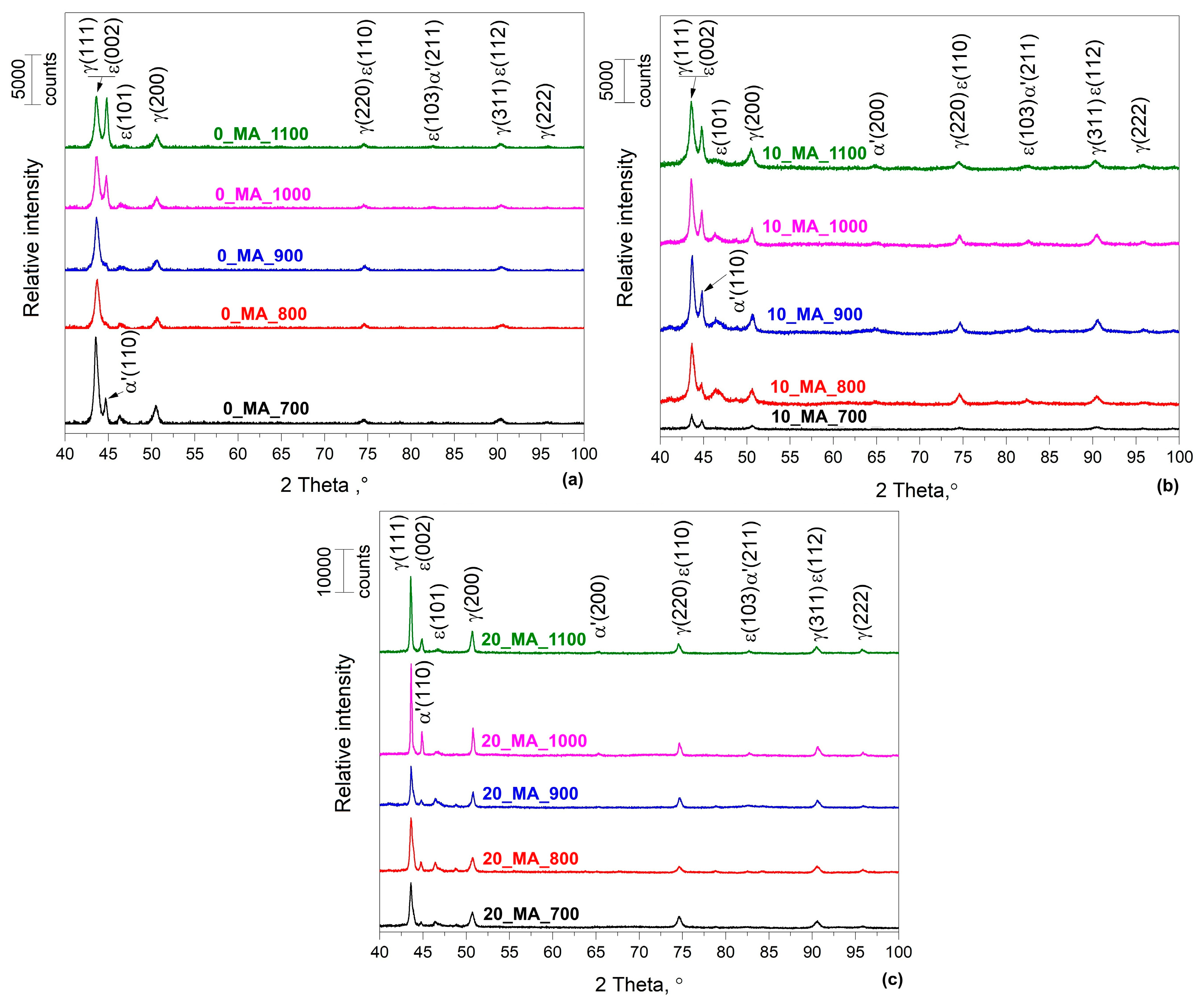
Figure 1. XRD patterns revealing the MA and ST temperature effects on the structure of a 66Fe-l4Mn-6Si-9Cr-5Ni SMA: (a) 0_MA; (b) 10_MA and (c) 20_MA.
Crystals 15 00105 g001
Figure 2. Variation in the amounts of the two martensitic phases determined by relative semi-quantitative evaluation of the XRD patterns from Figure 1, revealing the MA fraction and ST temperature effects: (a) α′—bcc and (b) ε—hcp.
Crystals 15 00105 g002
Figure 3. Typical micrographs illustrating the morphology of specimens 20_MA_1000: (a) OM; (b) SEM.
Crystals 15 00105 g003
Figure 4. Illustration of the capacity of 20_MA_1000 specimens to develop a free-recovery SME: (a) evolution of the displacement of the free end of the specimen during the first heating; (b) variation in displacement of the free end of the specimen with temperature during the heating of the fifth training cycle.
Crystals 15 00105 g004
Figure 5. Representative strain diagrams in tension to rupture revealing the MA and ST temperature effects: (a) 0_MA; (b) 10_MA and (c) 20_MA.
Crystals 15 00105 g005
Figure 6. XRD patterns revealing tensile pre-straining effects on the structure of a 66Fe-l4Mn-6Si-9Cr-5Ni SMA: (a) 0_MA_700; (b) 0_MA_800; (c) 0_MA_900; (d) 0_MA_1000; (e) 0_MA_1100; (f) 10_MA_700; (g) 10_MA800; (h) 10_MA_900; (i) 10_MA_1000; (j) 10_MA_1100; (k) 20_MA_700; (l) 20_MA_800; (m) 20_MA_900; (n) 20_MA_1000 and (o) 20_MA_1100.
Crystals 15 00105 g006aCrystals 15 00105 g006b
Figure 7. SEM micrographs illustrating the morphological effects on the microstructures of specimens with different MA volumes and ST temperatures, caused by different tensile pre-straining degrees: (a) 0_MA_700—2%; (b) 0_MA_900—2%; (c) 0_MA_1100—1.5%; (d) 10_MA_700—2.4%; (e) 10_MA_900—2.7%; (f) 10_MA_1100—2.5%; (g) 20_MA_700—1%; (h) 20_MA_900—3% and (i) 20_MA_1100—3%.
Crystals 15 00105 g007
Figure 8. HR-SEM micrographs exemplifying the substructure of α′—bcc thermally induced martensite at specimen 0_MA_1100: (a) overall aspect of martensite plates, with two marked zone details; (b) magnified detail of zone I; (c) magnified detail of zone II; (d) high-resolution image of zone I with internal sub-bands; (e) high-resolution image of zone II with internal sub-bands. The internal sub-bands are marked by arrows.
Crystals 15 00105 g008
Table 1. Values of the amounts of the two martensitic phases determined by relative semi-quantitative evaluation of the diffraction maxima from Figure 6.
SpecimenPre-Strainα′(110)/
γ(200)
ε(101)/
γ (200)
SpecimenPre-Strainα′(110)/
γ(200)
ε(101)/
γ(200)
SpecimenPre-Strainα′(110)/
γ(200)
ε(101)/
γ(200)
%%%%%%%%%
0_MA_70001.40540.475910_MA_70001.82740.823020_MA_70000.51770.5372
0.71.06870.38181.52.25700.46431.00.58470.5699
1.21.08460.96202.41.12720.97161.40.89080.8817
1.40.88290.8755 1.80.90490.9244
2.01.07570.9785
2.11.01410.9920
0_MA_80000.95520.942410_MA_80001.12841.003120_MA_80000.94700.9385
1.31.77791.67631.01.47090.63981.70.49660.4808
1.71.42871.06101.20.97780.93531.90.91720.9067
2.01.50650.95191.41.11140.96582.20.94120.9351
2.11.23551.0539
3.31.00200.9964
0_MA_90001.97920.962610_MA_90001.19580.970520_MA_90000.94310.9551
11.43690.85141.51.21870.45332.10.49160.6102
1.60.98370.96972.41.03580.89192.30.83310.9290
1.81.02490.97752.71.08980.92853.0.97440.9705
2.01.06191.0039
0_MA_100001.09150.974010_MA_100001.08480.976720_MA_100001.98280.8857
1.20.89950.32751.41.96530.41711.40.82521.7065
1.70.90180.88991.81.05260.90542.10.87721.3079
3.41.02820.98472.00.93900.885031.02691.2301
4.00.99430.9761
0_MA_110001.42550.964210_MA_110001.07600.961420_MA_110001.97490.9423
1.11.33670.18091.51.73460.25342.00.65980.2533
1.50.98070.91912.51.66680.88023.00.81860.8118
2.01.14310.9320 3.20.99550.8897
2.11.00090.9390
3.81.00380.9877
Disclaimer/Publisher’s Note: The statements, opinions and data contained in all publications are solely those of the individual author(s) and contributor(s) and not of MDPI and/or the editor(s). MDPI and/or the editor(s) disclaim responsibility for any injury to people or property resulting from any ideas, methods, instructions or products referred to in the content.