Abstract
Modeling the electromagnetic (EM) behavior of CORC® cables presents significant computational challenges due to the coexistence of thin superconducting tapes and thick structural formers. This creates a strongly multiscale problem, making traditional FEM-based approaches cumbersome, as they require extremely fine meshes to accurately resolve the different geometric scales. Integral Equation Methods (IEMs), on the other hand, are well-suited for magnetization loss analysis in multiscale superconducting structures, as they avoid modeling non-EM-active parts of the domain. This greatly reduces the effort involved in meshing the computational domain. In this work, we propose an IEM that couples surface and volumetric models to perform transient nonlinear analysis of CORC®-like superconducting cables.
1. Introduction
The second generation of High Temperature Superconductors (HTS), based on REBCO and arranged in Conductor-on-Round-Core (CORC®) wires, is attracting growing interest in electrical engineering. Their applications extend beyond power distribution to high-energy physics, including magnets for nuclear fusion devices and particle accelerators [1,2]. In this context, numerical analysis plays a crucial role throughout both the design and operational phases: it reduces prototyping costs and enables the management or even prevention of disruptive events, such as quenching, through advanced monitoring strategies [3,4].
In the literature, two main approaches are proposed for the electromagnetic (EM) analysis of superconducting CORC® cables: Finite Element Methods (FEMs) and Integral Equation Methods (IEMs) [5]. IEMs have been applied to REBCO coils under 2D assumptions in [6,7]. As shown in Figure 1, a typical CORC® cable consists of two main components: thin HTS tapes helically wound around a thick copper (Cu) former. The strong geometric disparity between the two is evident; the HTS tapes have a thickness of ∼0.1 mm, with a REBCO layer of about 1 μm [8,9], while the Cu former has a typical radius of ∼2.8 mm. This scale separation makes CORC® cables a clear case of multiscale modeling.
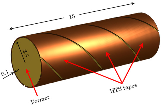
Figure 1.
Schematic representation of CORC® cable including HTS tape and former. Units in mm.
Standard FEM approaches, based on magnetic field formulations (e.g., the H-formulation), have been applied to CORC® cables by modeling both the HTS layer and the Cu former as bulk conductors [10,11,12]. While effective, this approach is computationally demanding and requires careful meshing of the computational domain. To reduce complexity, alternative formulations have been proposed in both the FEM and IEM frameworks, where the HTS layer is represented as a surface in 3D under the assumption of uniform current density across its thickness [5,13]. A hybrid strategy, using surface discretization for thin parts and volumetric discretization for the thick domains, has proven to be a practical solution for the EM analysis of such multiscale structures [14]. Notably, this approach has already been employed within the IEM framework to investigate the influence of passive conducting structures in magnetic confinement fusion devices [15,16].
In this work, the surface–volume IEM is extended to analyze the EM response of CORC® cables, particularly the AC losses, subjected to a time-varying external field, taking into account the nonlinear behavior of the HTS material. Different loss mechanisms occur in REBCO tapes, including coupling losses and hysteresis (magnetization) losses [17,18]. In the following analysis, only the AC losses associated with current loops in the tapes are considered. These losses are induced by an external sinusoidal magnetic field.
2. Materials and Methods
In this section, the formulation of the electromagnetic problem adopted for the analysis of CORC® cables is presented. The model is derived from the magneto-quasistatic approximation of Maxwell’s equations:
where is the electric field, is the current density, is the magnetic induction, the magnetic field, and is the position vector.
The H and formulations, derived from Equations (1) and (2), are the most widely used approaches for solving the EM problem in superconducting cables and are implemented in several commercial softwares [19,20]. They rely upon the solution in terms of and the magnetic scalar potential within the computational domain.
Hereafter, an integral equation (IE) approach derived from the potential-based Faraday’s law coupled with the charge continuity equation is considered. If a time-varying incident electric field exists in , these equations are expressed as follows:
where is the magnetic scalar potential satisfying , and is the electric scalar potential. The current density is related to the magnetic scalar potential through an integral expression:
By substituting Ohm’s law , where is the resistivity, and Equation (5) into Equation (3), a system of two equations with the unknowns and V is obtained, leading to the current–potential integral formulation detailed in [21]. The main advantage of this approach lies in the fact that only the electromagnetically active regions of , i.e., the conductive domains, need to be modeled, since the current density is nonzero exclusively within these regions.
2.1. Modeling Electrical Resistivity
The electromagnetic behavior of superconducting materials is modeled using a nonlinear form of Ohm’s law. Various expressions have been proposed in the literature, typically based on a power-law formulation [22]:
where and are the critical electric field and the critical current density, while is an integer exponent. For HTS materials, the magnetic flux density () typically affects both the n-value and the critical current density [23]. In particular, for the REBCO layer in CORC® cables, is commonly expressed as a function of as follows:
where the parameters have the same meaning as in [24]. It is worth noting that Equation (7) can be extended to account for strain and temperature dependence, as discussed in [13,25,26,27]. Such extensions are particularly useful for describing the behavior of CORC® cables under bending or during quenching events.
For the normal core of CORC® cables, typically made of copper, a linear Ohm’s law is employed. It is worth noting that temperature effects can also be incorporated in the core; however, in this preliminary study, which focuses solely on the electromagnetic problem, thermal effects are neglected.
2.2. Numerical Solution
Based on the integral formulation described in Section 2, a numerical scheme is developed by subdividing into finite elements. As stated in Section 1, in practical applications, can be divided into multiple subdomains with different geometric scales, such as thick volumetric regions (denoted as ) and thin volumetric regions, which can be represented as surfaces in (denoted as ). In the following, is constructed by extracting the mid-surface of the corresponding thin volumetric domain.
After partitioning with triangular or quadrilateral elements, and with tetrahedra or hexahedra, the unknowns and V are expressed in terms of vector () and piecewise constant () basis functions:
In Equation (8), is the number of faces of the volumetric mesh, and is the number of edges of the surface mesh. It is worth mentioning that normalized RWG basis functions [28] are used for surface current density, and a rescaling process is applied to account for the thickness of the thin regions. By Galerkin testing Equations (3) and (4), the following nonlinear Differential Algebraic Equation (DAE) is assembled:
A detailed description of the evaluation of matrix entries can be found, e.g., in [29].
Since the computational domain is divided into and , the matrices and vectors in (9) are correspondingly expanded as follows:
and
It is worth noting that and , the discrete counterparts of the divergence operator, are sparse and can therefore be stored efficiently in memory. In contrast, the inductance matrices , , and , arising from the integral expression in Equation (5), are dense. To manage the quadratic memory scaling, low-rank representations, such as hierarchical matrices, are typically employed. A detailed discussion of these techniques is beyond the scope of this work, but the interested reader is referred to [30].
The coupling between surface and volumetric elements is handled via the inductance matrix . For CORC® cables, the volumetric domain corresponds to the Cu former, a linear material, making a constant sparse matrix. The HTS tapes are represented by , where nonlinearity appears in the resistance matrix . This matrix is also sparse, but its entries depend on the current vector (i.e., the current density) at a given time, according to the law defined in Equation (6).
The algorithmic procedure used to solve the EM problem with the proposed approach can be summarized as follows:
- Define the geometry and generate the mesh for and ;
- Construct and store the time-independent matrices , , (for ), and , using a suitable data-sparse representation;
- Define the mapping for constructing the resistance matrix;
- Specify the external field excitation;
- Solve the nonlinear time-dependent problem.
For a given geometry and material configuration, steps 1–3 can be carried out offline, with the corresponding quantities stored in memory, while the remaining steps are performed online. Indeed, if the external excitation changes, the system matrices do not need to be recomputed from scratch. The procedure can be easily extended to consider also a nonlinear resistivity for .
The DAE in Equation (9) can be recast into the state-space form commonly used in control theory:
where :
Solving the nonlinear time-dependent problem expressed by Equation (12) requires the additional evaluation of the Jacobian matrix , as described in [21]. This matrix is sparse, and the mapping can be constructed through a procedure analogous to the one used in step 3 [21]. In what follows, the time integration is performed with a fixed time step using an implicit Euler scheme; thus, no adaptive time stepping is employed. By discretizing Equation (12) using the Euler method, we obtain the following state update equation:
where is the solution vector at k-th time step. The tolerance of the nonlinear solver (), based on the Newton–Raphson (N-R) method, is iteratively adjusted at time t using the following rule:
where in this case, while the maximum number of N-R iterations is set to 100. At a given time step, the nonlinear solver also requires the solution of the following system for a given right-hand-side vector [31]:
where, in this case:
The system expressed by Equation (16) is solved with the iterative GMRES method, with a tolerance of , exploiting the Algebraic Multigrid (AMG) preconditioner [32]. It is worth mentioning that hierarchical matrix-based solvers [33] can be conceived in this step, and will be the subject of future research activities.
In contrast to the IE, the FEM-based H and formulations introduced in Section 2 present several challenges in meshing the computational domain. First, must include not only the entire CORC® cable but also a surrounding air region, where the electromagnetic fields extend. Second, generating a volumetric mesh for the entire becomes problematic when modeling a single REBCO layer of thickness ∼1 μm. To address this, the literature often employs a homogenization approach, in which the thickness of the superconducting tapes is artificially increased (typically by a factor of 100) with proper resistivity scaling, thereby making the meshing process computationally feasible [11,34].
The coupling strategy between the surface and volume discretizations used in the IE approach, along with the associated system matrices, is illustrated in Figure 2.
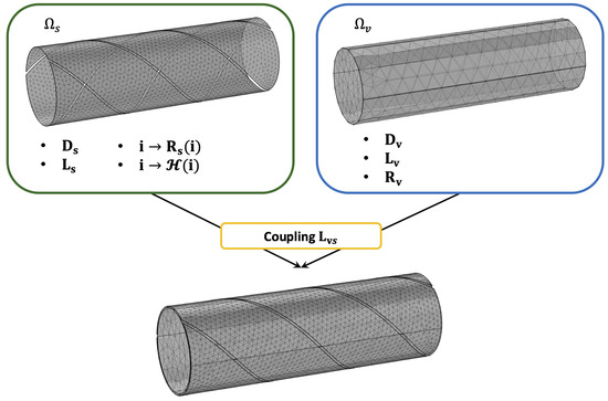
Figure 2.
Coupling strategy of surface–volume discretizations for the CORC® cable using the IE approach.
Electrical Resistivity Reconstruction
At a given time, following Equation (6), a uniform current density within each mesh cell of is required and is obtained through Equation (8), corresponding to a linear map described by a sparse matrix [35]. Under the previous assumption, it is also possible to build the magnetic flux density within each element, as required e.g., in Equation (7), using the analytical expression given by [36]:
where is the normal surface vector and is the analytical form of the surface integral detailed in [36].
2.3. Losses Calculation
In this study, the EM analysis is conducted to evaluate the instantaneous AC losses of the superconducting structure, defined as follows:
From the numerical point of view, the integral is evaluated with a quadrature rule, approximating the integrand function with its value at the center of each mesh element ():
where is the measure (area/volume) of the h-th (surface/volumetric) element. For sinusoidal excitations, such as incident fields or transport currents with electrical period T and amplitude , the AC magnetization losses are computed as follows:
Analytical power-law models expressing are usually extracted to characterize the superconducting cables [37]. Following [19], the integral in Equation (21) is evaluated during the second half of the first excitation period to disregard transient effects.
3. Results
In this section, the proposed IE approach, implemented in MATLAB R2025a using MEX-Fortran functions, is tested by first solving a benchmark model and comparing the results with those obtained from a commercial FEM software. Then, the AC losses caused by a time-varying external field are computed for a CORC® cable. To simplify the analysis, it is assumed that n and are field-independent in both cases. In what follows, the mesh data (coordinates, connectivity) generated with COMSOL® Multiphysics 6.3 are imported into the MATLAB environment using proprietary functions. The simulation was performed on a machine Intel® Xeon® w5-2465X @ 3.10 GHz, 16 core, 32 thread with 128 GB RAM.
3.1. HTS Plate Above Conductive Substrate
We consider the geometry shown in Figure 3 inspired from benchmark#2 listed in [38], corresponding to a thin HTS disk above a conductive substrate made of iron ( m), embedded in a uniform vertical magnetic flux density with sinusoidal trend with mT and Hz, corresponding to ms. The incident electric field is constructed analytically from Equation (1), resulting in the following:
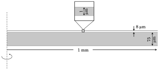
Figure 3.
Two-dimensional axisymmetric geometry of the benchmark model.
The power law of Equation (6) is used for the HTS disk with , mV/m, and A/m2.
The proposed surface–volume IE framework, based on a full 3D model of the geometry, is compared against the formulation implemented in the FEM software COMSOL® Multiphysics. The IE discretization employs triangular elements for the HTS disk and tetrahedral elements for the substrate. Exploiting the axial symmetry of the problem, a 2D mesh with 3418 elements is used for the FEM formulation. The conductive structure is embedded in an air domain with a circular shape and a radius of 6 mm.
Within the time interval , the computed AC losses for the HTS disk are presented in Figure 4, together with the instantaneous absolute error, computed as follows:
The trend of is reported by considering three levels of discretization for the HTS, with , , and elements. Moreover, the root mean squared error (RMSE) is computed as follows:
which is also reported in Table 1 for the three cases.
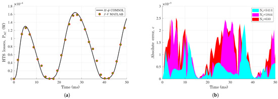
Figure 4.
(a) AC losses HTS disk for the benchmark model (b); absolute error.

Table 1.
Root mean squared error (RMSE) for three discretization levels.
Figure 5 compares the norm of the current density obtained with the two methods, showing good agreement between the two approaches.
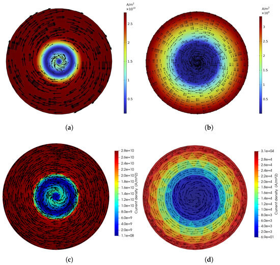
Figure 5.
Top view of the current density norm at ms. (a) HTS disk with . (b) Iron substrate with . (c) HTS disk with . (d) Iron substrate with .
Looking at Figure 5a,c, it can be noticed that in the core of the HTS layer, the inversion of the current density vectors appears and is caught by both modeling strategies.
The effect of the amplitude of the incident flux density is now examined through the evaluation of the magnetization loss density Q expressed by Equation (21) using three values for : 25 mT, 40 mT, 50 mT, 80 mT, and 100 mT. Figure 6 confirms a good agreement between the proposed strategy and the reference solution computed with the approach. Moreover, a straight line in the log-log plane is observed for , allowing the construction of a power-law expression for the loss density in the following form:
where mT.

Figure 6.
Magnetization loss density for the benchmark model under varying peak value of the external field. The extracted power-law expression of Equation (25), is also included.
3.2. CORC® Cable
The CORC® cable model illustrated in Figure 1 is analyzed in this section. The cable is characterized by three HTS tapes of 1 μm thickness, whose resistivity is given in Equation (7) with , mV/m, and A/m2. The cylindrical former is made of Cu with a constant resistivity m. The cable is subjected to an incident electric field, expressed as follows:
with mT and Hz. The transient analysis is solved for one electric period corresponding to ms. A triangular mesh with elements is used for the HTS, while a tetrahedral mesh of cells is used for the Cu.
The trend of AC losses due to the HTS material and the Cu within the interval is reported in Figure 7. It can be noticed that the AC losses are comparable in this case due to the high value of the current density induced in the former. A detailed map of the current density in HTS tapes and the former is illustrated in Figure 8 for the time instant ms. The current density in the HTS tapes is predominantly concentrated near their boundaries, consistent with results reported in the literature [39].
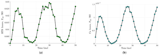
Figure 7.
AC losses of CORC® cable computed with the formulation. (a) HTS tapes. (b) Cu former.
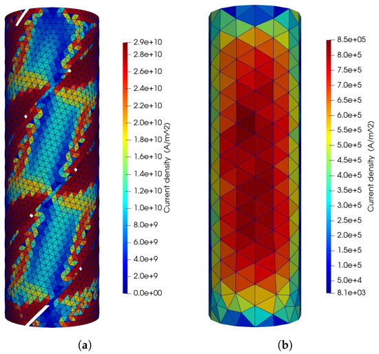
Figure 8.
Current density norm at ms computed with the formulation. (a) HTS tapes. (b) Cu former.
To conclude, a summary of the computational resources, expressed in terms of the solution time, is provided in Table 2. It can be observed that the time required to build the time-independent system matrices and the excitation is negligible compared to that needed for solving the transient nonlinear problem. The latter is carried out using non-optimized proprietary MATLAB scripts, and the code efficiency lies beyond the scope of this study. It is worth mentioning that a major bottleneck is observed in the number of calls of the maps and and the solution of the system of Equation (16). In the future, we are planning to explore hierarchical matrix-based solvers and model order reduction techniques to speed up the simulation time.

Table 2.
Computational burden of formulation for CORC® cable example.
4. Conclusions
An IEM coupling of surface and volumetric models for the transient nonlinear analysis of CORC® cables is presented. By following an IE approach and thereby avoiding the meshing of non-conductive domains, the modeling effort required to solve the electromagnetic problem is significantly reduced. The proposed method, possibly enhanced through acceleration techniques such as hierarchical matrices, is demonstrated to be effective for addressing multiscale problems involving thin superconducting layers and bulk normal materials. Future work will extend the approach to include thermal effects, with the aim of modeling quenching phenomena.
Author Contributions
Conceptualization, F.L. and F.D.; methodology, F.L.; software, F.L.; formal analysis, F.L. and F.D.; writing—original draft preparation, F.L.; writing—review and editing, F.D. All authors have read and agreed to the published version of the manuscript.
Funding
This research received no external funding.
Data Availability Statement
The original contributions presented in this study are included in the article. Further inquiries can be directed to the corresponding author.
Conflicts of Interest
The authors declare no conflicts of interest.
References
- van der Laan, D.C.; Weiss, J.D.; McRae, D.M. Status of CORC® cables and wires for use in high-field magnets and power systems a decade after their introduction. Supercond. Sci. Technol. 2019, 32, 033001. [Google Scholar] [CrossRef]
- Zhai, Y.; van der Laan, D.; Connolly, P.; Kessel, C. Conceptual design of HTS magnets for fusion nuclear science facility. Fusion Eng. Des. 2021, 168, 112611. [Google Scholar] [CrossRef]
- Sorti, S.; Balconi, L.; Rossi, L.; Santini, C.; Statera, M. Toward Real-Time Electromagnetic Simulations of HTS Non-Insulated Coils Through Proper Orthogonal Decomposition. IEEE Trans. Appl. Supercond. 2025, 35, 4901505. [Google Scholar] [CrossRef]
- Huang, Y.; Yazdani-Asrami, M.; Song, W. A Deep Learning-Based Ultra-Fast Surrogate Model for AC Loss Estimation in Superconductors Using COMSOL. IEEE Access 2025, 13, 153845–153854. [Google Scholar] [CrossRef]
- Lucchini, F. Evaluating Magnetization Losses in 3-D CORC Tapes with Integral and Finite-Element Methods. IEEE Trans. Appl. Supercond. 2025, 35, 5901808. [Google Scholar] [CrossRef]
- Chow, C.C.T.; Grilli, F.; Chau, K.T. Numerical modelling of HTS tapes under arbitrary external field and transport current via integral method: Review and application to electrical machines. Supercond. Sci. Technol. 2023, 36, 115027. [Google Scholar] [CrossRef]
- Lai, L.; Gu, C. AC loss calculation in REBCO coils or stacks by solving the equation of motion for current using an integration approach. Supercond. Sci. Technol. 2020, 34, 015003. [Google Scholar] [CrossRef]
- Anvar, V.A.; Ilin, K.; Yagotintsev, K.A.; Monachan, B.; Ashok, K.B.; Kortman, B.A.; Pellen, B.; Haugan, T.J.; Weiss, J.D.; van der Laan, D.C.; et al. Bending of CORC® cables and wires: Finite element parametric study and experimental validation. Supercond. Sci. Technol. 2018, 31, 115006. [Google Scholar] [CrossRef]
- Zhang, Y.; He, J.; Chen, T.; Wang, J.; Du, G. Study on Loss and Thermal Properties of a Superconducting Pancake Coil under Self-Field and Analysis of Its Influencing Factors. Crystals 2022, 12, 1314. [Google Scholar] [CrossRef]
- Tian, M.; Yang, J.; Shen, B.; Öztürk, Y.; Ma, J.; Li, C.; Shah, A.; Patel, I.; Li, J.; Coombs, T. Magnetization Loss Characteristics in Superconducting Conductor on Round Core Cables with a Copper Former. IEEE Trans. Appl. Supercond. 2021, 31, 4803204. [Google Scholar] [CrossRef]
- Shen, B.; Chen, X.; Fu, L.; Zhang, M.; Chen, Y.; Sheng, J.; Huang, Z.; Wang, W.; Zhai, Y.; Yuan, Y.; et al. A Simplified Model of the Field Dependence for HTS Conductor on Round Core (CORC) Cables. IEEE Trans. Appl. Supercond. 2021, 31, 4803405. [Google Scholar] [CrossRef]
- Yang, J.; Li, C.; Tian, M.; Liu, S.; Shen, B.; Hao, L.; Ozturk, Y.; Coombs, T. Analysis of AC transport loss in conductor on round core cables. J. Supercond. Nov. Magn. 2022, 35, 57–63. [Google Scholar] [CrossRef]
- Wang, Y.; Zhang, M.; Grilli, F.; Zhu, Z.; Yuan, W. Study of the magnetization loss of CORC® cables using a 3D T-A formulation. Supercond. Sci. Technol. 2019, 32, 025003. [Google Scholar] [CrossRef]
- Li, Y.; Marek, D.; Triverio, P. MultiAIM: Fast Electromagnetic Analysis of Multiscale Structures Using Boundary Element Methods. IEEE Trans. Antennas Propag. 2024, 72, 5877–5891. [Google Scholar] [CrossRef]
- Bettini, P.; Passarotto, M.; Specogna, R. Coupling Volume and Surface Integral Formulations for Eddy-Current Problems on General Meshes. IEEE Trans. Magn. 2018, 54, 7203604. [Google Scholar] [CrossRef]
- Frescura, A.; Bettini, P. Hierarchical matrices accelerated large-scale eddy current problems with coupled volume and surface integral equations. J. Phys. Conf. Ser. 2025, 3027, 012005. [Google Scholar] [CrossRef]
- Gömöry, F.; Šouc, J.; Solovyov, M.; Ries, R.; Hintze, C.; Landvogt, S.; Pekarčíková, M.; Christensen, J.J.; Bahl, C.R.H.; Jørgensen, N.O.; et al. Hysteresis and Coupling Loss in Filamentized REBCO Tapes. IEEE Trans. Appl. Supercond. 2025, 35, 5900205. [Google Scholar] [CrossRef]
- Zappatore, A.; De Marzi, G.; Uglietti, D. Impact of Hysteresis Losses in Hybrid (HTS-LTS) Coils for Fusion Applications. IEEE Access 2023, 11, 100465–100478. [Google Scholar] [CrossRef]
- Shen, B.; Grilli, F.; Coombs, T. Review of the AC loss computation for HTS using H formulation. Supercond. Sci. Technol. 2020, 33, 033002. [Google Scholar] [CrossRef]
- Benkel, T.; Lyly, M.; Ruuskanen, J.; Halbach, A.; Lahtinen, V.; Riva, N. Modelling of a Large-Scale Non-Insulated Non-Planar HTS Stellarator Coil Using Quanscient Allsolve. IEEE Trans. Appl. Supercond. 2025, 35, 4202505. [Google Scholar] [CrossRef]
- Lucchini, F.; Torchio, R.; Morandi, A.; Dughiero, F. A Fast Integral Equation J − φ Formulation for Superconducting Structures. IEEE Trans. Appl. Supercond. 2024, 34, 5901808. [Google Scholar] [CrossRef]
- Sirois, F.; Grilli, F.; Morandi, A. Comparison of Constitutive Laws for Modeling High-Temperature Superconductors. IEEE Trans. Appl. Supercond. 2019, 29, 8000110. [Google Scholar] [CrossRef]
- Nibbio, N.; Stavrev, S.; Dutoit, B. Finite element method simulation of AC loss in HTS tapes with B-dependent E-J power law. IEEE Trans. Appl. Supercond. 2001, 11, 2631–2634. [Google Scholar] [CrossRef]
- Grilli, F.; Sirois, F.; Zermeño, V.M.R.; Vojenčiak, M. Self-Consistent Modeling of the Ic of HTS Devices: How Accurate do Models Really Need to Be? IEEE Trans. Appl. Supercond. 2014, 24, 8000508. [Google Scholar] [CrossRef]
- Viarengo, S.; Freschi, F.; Savoldi, L. CORC Cables: Numerical Characterization of the Critical Current After Bending. IEEE Trans. Appl. Supercond. 2024, 34, 4801605. [Google Scholar] [CrossRef]
- Li, X.; Ren, L.; Xu, Y.; Shi, J.; Chen, X.; Chen, G.; Tang, Y.; Li, J. Calculation of CORC Cable Loss Using a Coupled Electromagnetic-Thermal T-A Formulation Model. IEEE Trans. Appl. Supercond. 2021, 31, 4802707. [Google Scholar] [CrossRef]
- Yan, J.; Gao, Y. Mechanical and electromagnetic properties of CORC cables under combined loads of axial tension and transverse compression. Cryogenics 2025, 147, 104045. [Google Scholar] [CrossRef]
- Xia, T.; Gan, H.; Wei, M.; Chew, W.C.; Braunisch, H.; Qian, Z.; Aygün, K.; Aydiner, A. An Enhanced Augmented Electric-Field Integral Equation Formulation for Dielectric Objects. IEEE Trans. Antennas Propag. 2016, 64, 2339–2347. [Google Scholar] [CrossRef]
- Bettini, P.; Passarotto, M.; Specogna, R. A Volume Integral Formulation for Solving Eddy Current Problems on Polyhedral Meshes. IEEE Trans. Magn. 2017, 53, 7204904. [Google Scholar] [CrossRef]
- Börm, S.; Grasedyck, L.; Hackbusch, W. Introduction to hierarchical matrices with applications. Eng. Anal. Bound. Elem. 2003, 27, 405–422. [Google Scholar] [CrossRef]
- Torchio, R.; Lucchini, F.; Schanen, J.L.; Chadebec, O.; Meunier, G. FFT-PEEC: A Fast Tool From CAD to Power Electronics Simulations. IEEE Trans. Power Electron. 2022, 37, 700–713. [Google Scholar] [CrossRef]
- Stüben, K. A review of algebraic multigrid. In Numerical Analysis: Historical Developments in the 20th Century; Brezinski, C., Wuytack, L., Eds.; Elsevier: Amsterdam, The Netherlands, 2001; pp. 331–359. [Google Scholar] [CrossRef]
- Pouransari, H.; Coulier, P.; Darve, E. Fast Hierarchical Solvers For Sparse Matrices Using Extended Sparsification and Low-Rank Approximation. SIAM J. Sci. Comput. 2017, 39, A797–A830. [Google Scholar] [CrossRef][Green Version]
- Wang, Y.; Jing, Z. Multiscale modelling and numerical homogenization of the coupled multiphysical behaviors of high-field high temperature superconducting magnets. Compos. Struct. 2023, 313, 116863. [Google Scholar] [CrossRef]
- Lucchini, F.; Frescura, A.; Torchio, R.; Alotto, P.; Bettini, P. Reduced order modeling for real-time monitoring of structural displacements due to electromagnetic forces in large scale tokamaks. Plasma Phys. Control. Fusion 2024, 66, 115002. [Google Scholar] [CrossRef]
- Fabbri, M. Magnetic Flux Density and Vector Potential of Uniform Polyhedral Sources. IEEE Trans. Magn. 2008, 44, 32–36. [Google Scholar] [CrossRef]
- Bykovsky, N.; Uglietti, D.; Wesche, R.; Bruzzone, P. AC Loss in HTS Fusion Cables: Measurements, Modeling, and Scaling Laws. IEEE Trans. Appl. Supercond. 2018, 28, 5900305. [Google Scholar] [CrossRef]
- HTS Modeling Workgroup. Benchmark #2. Available online: https://htsmodelling.com/ (accessed on 25 August 2025).
- Viarengo, S.; Brouwer, L.; Ferracin, P.; Freschi, F.; Riva, N.; Savoldi, L.; Wang, X. A New Coupled Electrodynamic T − A and Thermal Model for the Critical Current Characterization of High-Temperature Superconducting Tapes and Cables. IEEE Access 2023, 11, 107548–107561. [Google Scholar] [CrossRef]
Disclaimer/Publisher’s Note: The statements, opinions and data contained in all publications are solely those of the individual author(s) and contributor(s) and not of MDPI and/or the editor(s). MDPI and/or the editor(s) disclaim responsibility for any injury to people or property resulting from any ideas, methods, instructions or products referred to in the content. |
© 2025 by the authors. Licensee MDPI, Basel, Switzerland. This article is an open access article distributed under the terms and conditions of the Creative Commons Attribution (CC BY) license (https://creativecommons.org/licenses/by/4.0/).