
Effect of Prewetting Cenospheres on Hydration Kinetics, Microstructure, and Mechanical Properties of Refractory Castables


Abstract
1. Introduction
2. Materials and Methods
2.1. Used Materials
2.2. Mixture Preparation
2.3. Methods
3. Results
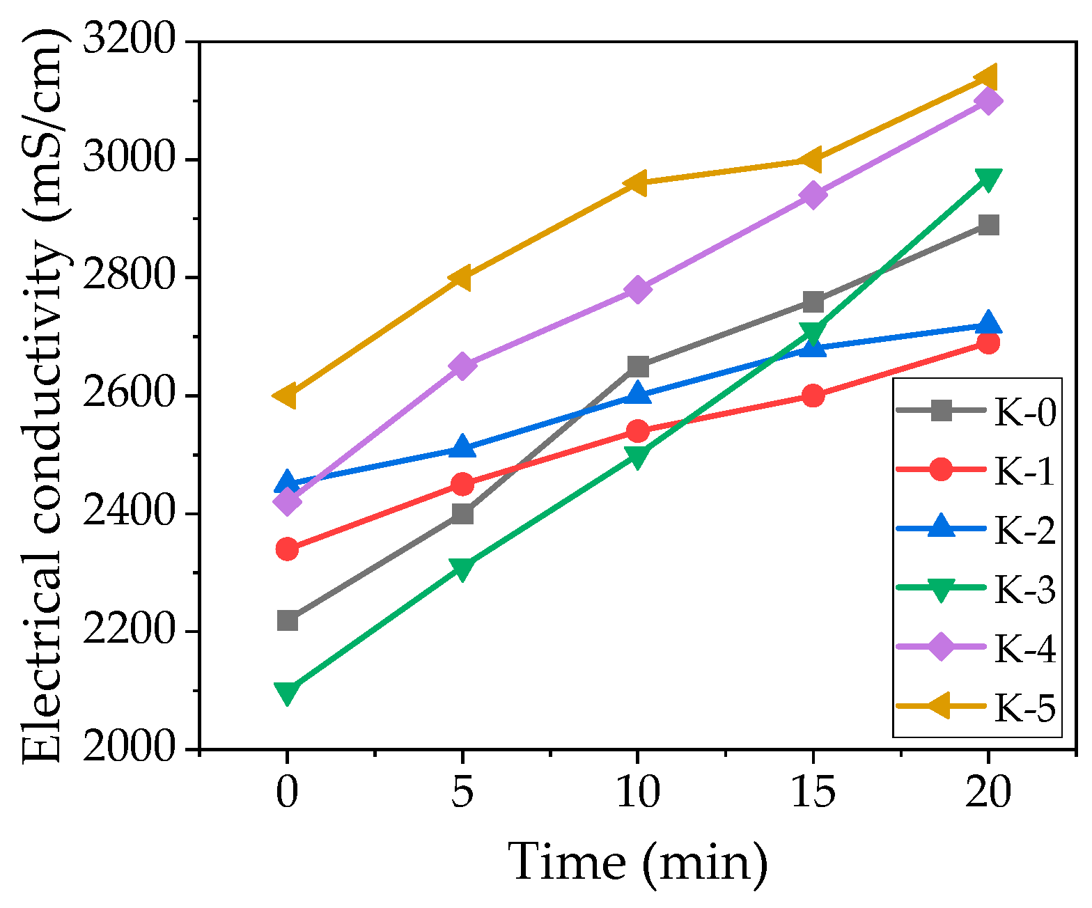
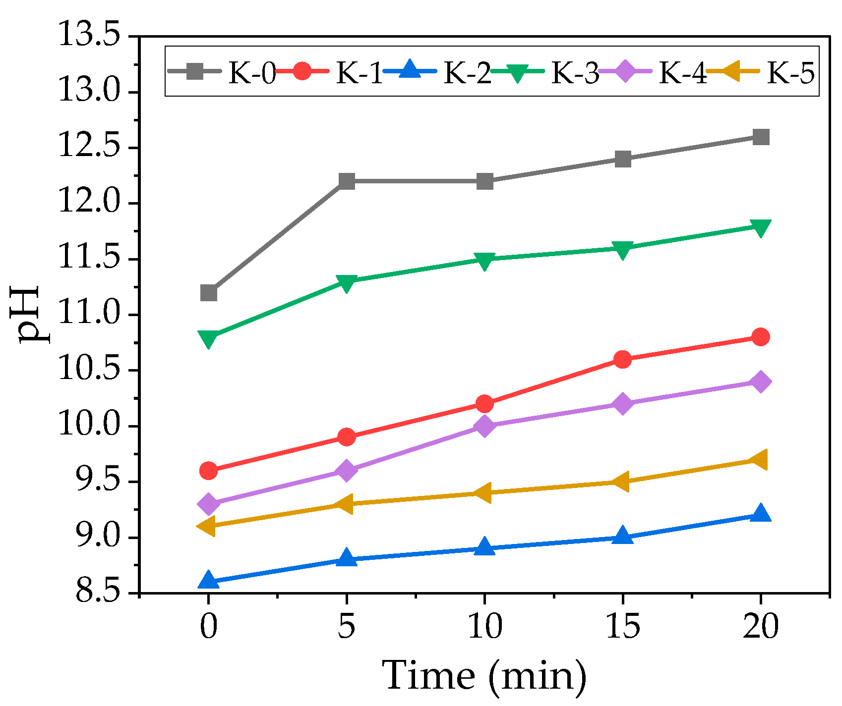
3.1. EC and pH
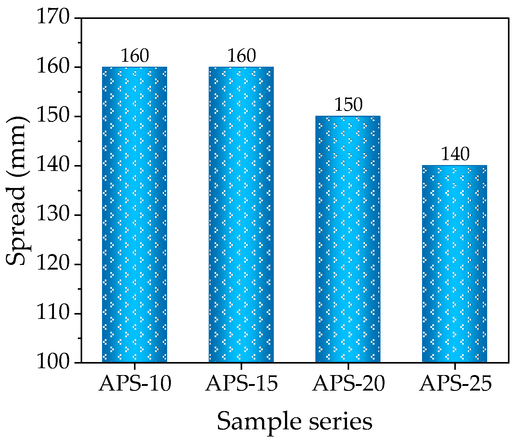
3.2. Spread
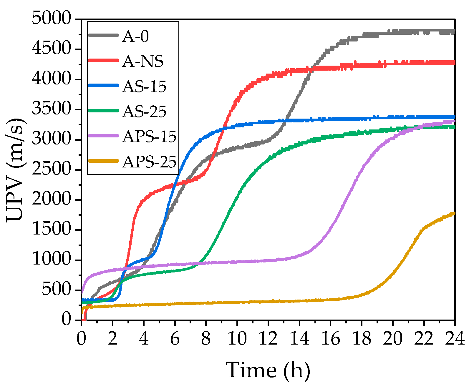
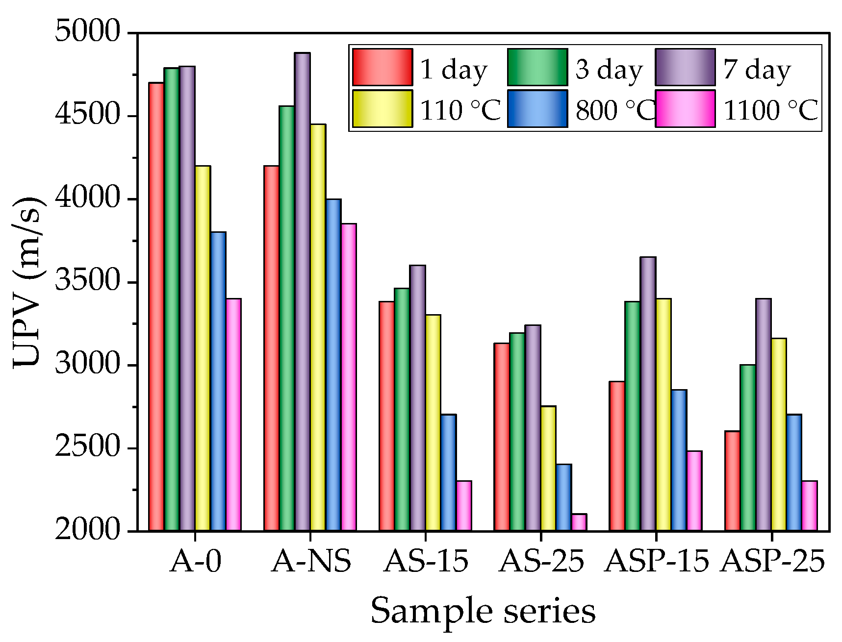
3.3. UPV
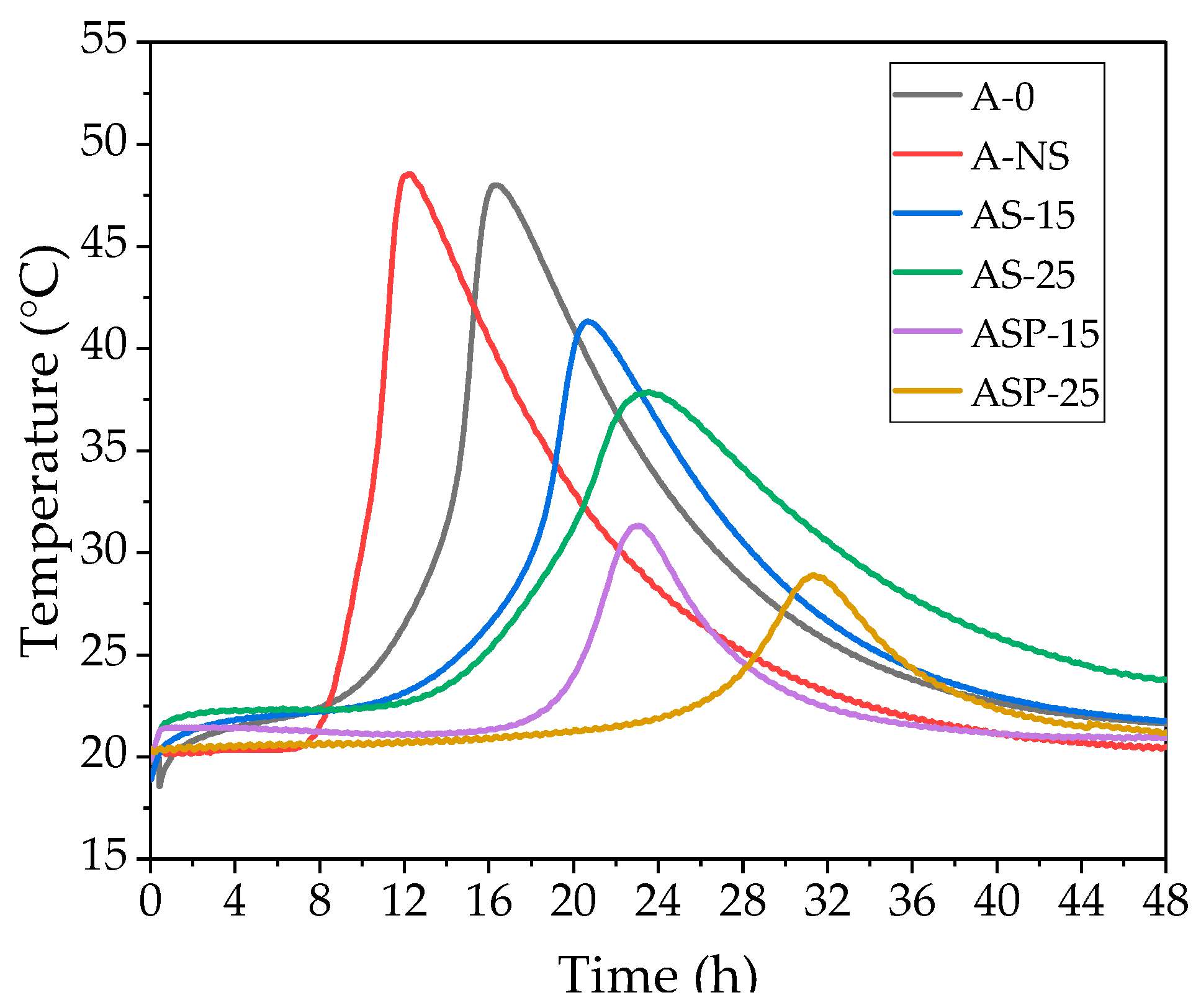
3.4. EXO Profile
4. Conclusions
- Test results show that the aqueous suspension of CSs and NS has an EC of 351 mS/cm and 667 mS/cm, and the pH of water suspension is 5.6 and 5.2. Therefore, in cement suspensions, an increase in the addition of CSs contributes to an increase in the initial EC values and a decrease in pH. On the contrary, NS in cement suspensions decreases the initial EC values but does not significantly change pH. CSs reduce the growth rate of EC and pH in suspensions and possibly inhibit the transition of cement minerals into the suspension. The presence of NS starts to promote cement dissolution and EC growing at the later hydration period.
- Due to the physical characteristics of CSs (porous surface), increasing the CS content in the composition up to 15% and up to 25% leads to deterioration of rheological properties, a decrease in the spread diameter of the castable mix by up to 14.5% and up to 31%. Due to water layers created on the CSs’ surface, the prewetting of CSs significantly improves the rheological properties of the castable mix. When the amount of prewetted CSs is 15% in the mix, the spread diameter increases by up to 5%, compared to the reference mix without CSs. A higher amount of CSs (up to 25%) leads to a decrease in the spread diameter of the castable mix by up to 7.9%.
- The tested electrical conductivity and pH of CSs and NS in suspensions influence the EXO profile and early structure formation of castable mixtures. An increased amount of non-prewetted and prewetted CSs to 15% and 25% prolongs the structure formation period in the mixes up to 1.9 and 3 times, prolongs the time of EXO maximum by up to 15% and 28.6%, and 23.5% and 73%, and reduces the EXO effect temperature by up to 10.1% and 20.2%, and by 31.4% and 40.4%, compared to the reference mix. In the case of non-prewetted CSs, it happens due to the porous nature of CSs, which adsorb the mixing water, resulting in the retardation of the dissolution process of cement minerals. In the case of prewetted CSs, more significant retardation is caused by water slowly diverging from the CSs to the environment. Using an amount of prewetted CSs of 25% contributes to the prolongation of hydration time. That is why applying such an amount of CSs in refractory castable technology must be carefully conducted.
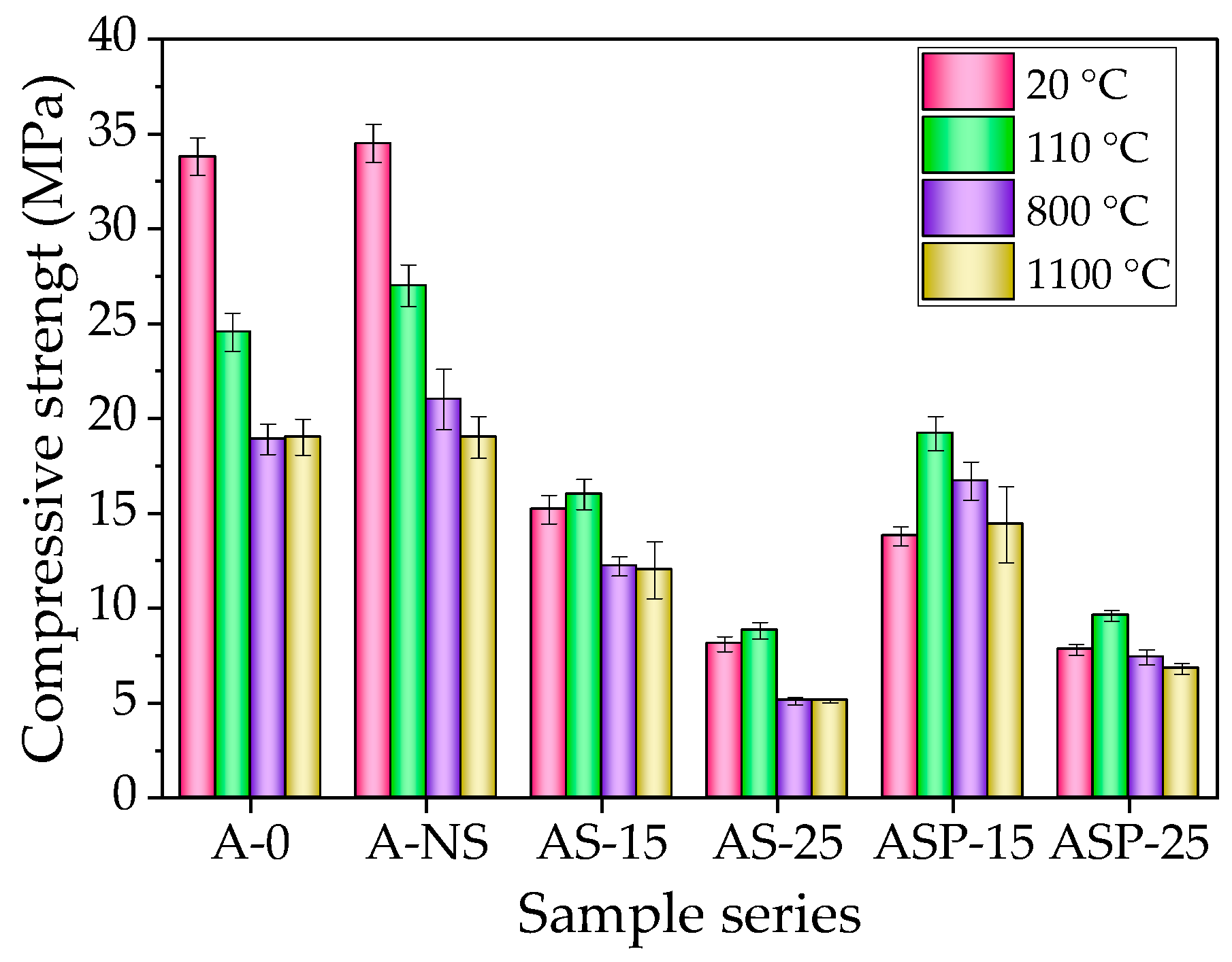
- Proportionally to the increase in the amount of non-prewetted and prewetted CSs in the composition, the density of the samples decreases by 30.3% and 28.5% after firing at a temperature of 1100 °C. Contrary to the control composition, the amount of CSs varied from 15% to 25%, increasing compressive strength by 5.3% and 8.6% (non-prewetted CSs) and 39.2% and 20.5% (prewetted CSs) after drying. After firing at 800 °C temperature, the same amounts of CSs in the composition decrease compressive strength by 41.9% and 75.7% (non-prewetted CS), and 20.3% and 64.5% in the case of prewetted CSs. After firing at 1100 °C, the mentioned amounts of CSs decreased compressive strength by 36.8% and 73.16% (non-prewetted CS) and by 24.0% and 64.2% in prewetted CS, compared to the control sample.
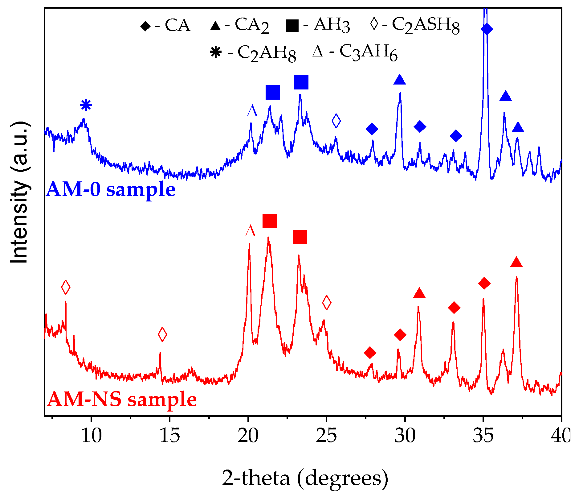
- During the drying process, the formed stratlingite in the composition with NS is responsible for the increase in mechanical properties; the structure is less susceptible to transformations during further heat treatment and, after firing, it promotes the early formation of anorthite.
- According to the parameters of the ratio of the strength of samples to their density, the amount of CSs of 15% in the composition is optimal. The shrinkage of the refractory castable samples with CSs decreased after firing at 800 °C from 0.3% (control sample) to 0.14% in the case of non-prewetted CSs and to 0.1% in the case of prewetted CSs. After firing at 1100 °C, the shrinkage of samples decreased from 0.34% (control sample) to 0.16% in the case of non-prewetted CSs and to 0.1% in the case of prewetted CSs. The highest CS amount allows for a significant reduction in shrinkage. The porous structures formed in samples containing 15% and 25% CSs effectively dissipate stresses generated during firing, significantly mitigating shrinkage and enhancing dimensional stability.
Author Contributions
Funding
Data Availability Statement
Conflicts of Interest
References
- Lu, J.; Zhang, Z.; Li, Y.; Liu, Z. Effect of Alumina Source on the Densification, Phase Evolution, and Strengthening of Sintered Mullite-Based Ceramics from Milled Coal Fly Ash. Constr. Build. Mater. 2019, 229, 116851. [Google Scholar] [CrossRef]
- Yan, S.; Ren, X.; Wang, W.; He, C.; Xing, P. Preparation of Eco-Friendly Porous Ceramic with Low Thermal Conductivity by High-Temperature Treatment of Foamed Solid Waste Based Geopolymer with Cenospheres. Constr. Build. Mater. 2023, 398, 131190. [Google Scholar] [CrossRef]
- Wang, C.; Liu, J.; Du, H.; Guo, A. Effect of Fly Ash Cenospheres on the Microstructure and Properties of Silica-Based Composites. Ceram. Int. 2012, 38, 4395–4400. [Google Scholar] [CrossRef]
- Agrawal, U.S.; Wanjari, S.P. Physiochemical and Engineering Characteristics of Cenosphere and Its Application as a Lightweight Construction Material—A Review. Mater. Today Proc. 2017, 4, 9797–9802. [Google Scholar] [CrossRef]
- Ranjbar, N.; Kuenzel, C. Cenospheres: A Review. Fuel 2017, 207, 1–12. [Google Scholar] [CrossRef]
- Zyrkowski, M.; Neto, R.C.; Santos, L.F.; Witkowski, K. Characterization of Fly-Ash Cenospheres from Coal-Fired Power Plant Unit. Fuel 2016, 174, 49–53. [Google Scholar] [CrossRef]
- Lv, L.; Zhang, X.; Šavija, B.; Zhang, M.; Han, K.; Zhang, H.; Pei, C.; Zhu, J.; Xing, F. Self-Healing of Cementitious Materials Using Sustainable Cenosphere-Based Manufactured Aggregate. Constr. Build. Mater. 2024, 419, 135361. [Google Scholar] [CrossRef]
- Salim, M.U.; Danish, A.; Torres, A.S.; Moro, C. Environmental Assessment of Cenosphere and GGBFS-Based Geopolymers: A Path to Greener Construction Materials. Environ. Impact Assess. Rev. 2025, 110, 107711. [Google Scholar] [CrossRef]
- Jaworek, A.; Sobczyk, A.T.; Czech, T.; Marchewicz, A.; Krupa, A. Recovery of Cenospheres from Solid Waste Produced by Coal-Fired Power Plants. Clean. Waste Syst. 2023, 6, 100109. [Google Scholar] [CrossRef]
- Patel, S.K.; Majhi, R.K.; Satpathy, H.P.; Nayak, A.N. Durability and Microstructural Properties of Lightweight Concrete Manufactured with Fly Ash Cenosphere and Sintered Fly Ash Aggregate. Constr. Build. Mater. 2019, 226, 579–590. [Google Scholar] [CrossRef]
- Leong, G.W.; Mo, K.H.; Ibrahim, Z.; Radwan, M.K.H.; Ling, T.C.; Sinoh, S.S. Lightweight Cementitious Composites Incorporating Fly Ash Cenospheres and Perlite Microspheres. Constr. Build. Mater. 2023, 404, 133226. [Google Scholar] [CrossRef]
- Rajesh, K.N.; Teena, J.; Raju, P.M. A Review on Performance of Cenosphere Utilization in Concrete. Mater. Today Proc. 2022, 62, 5567–5570. [Google Scholar] [CrossRef]
- Danish, A.; Mosaberpanah, M.A.; Tuladhar, R.; Salim, M.U.; Yaqub, M.A.; Ahmad, N. Effect of Cenospheres on the Engineering Properties of Lightweight Cementitious Composites: A Comprehensive Review. J. Build. Eng. 2022, 49, 104016. [Google Scholar] [CrossRef]
- Wu, Y.; Wang, J.Y.; Monteiro, P.J.M.; Zhang, M.H. Development of Ultra-Lightweight Cement Composites with Low Thermal Conductivity and High Specific Strength for Energy Efficient Buildings. Constr. Build. Mater. 2015, 87, 100–112. [Google Scholar] [CrossRef]
- Agrawal, U.S.; Wanjari, S.P. Light-Weight and High Thermal Insulation Building Material; a Comparative Study between Cenosphere & Fly Ash. Mater. Today Proc. 2023. [Google Scholar] [CrossRef]
- Zhang, H.; Ma, W.; Gao, F.; Ge, Z.; Yang, M.; Fang, H.; Šavija, B. Rheology, Shrinkage, Mechanical Properties and Microstructure of Ultra-Light-Weight Concrete with Fly Ash Cenospheres. J. Build. Eng. 2024, 98, 111258. [Google Scholar] [CrossRef]
- Kavinkumar, V.; Priya, A.K.; Praneeth, R. Strength of Light Weight Concrete Containing Fly Ash Cenosphere. Mater. Today Proc. 2023. [Google Scholar] [CrossRef]
- Huang, Z.; Liew, J.Y.R.; Li, W. Evaluation of Compressive Behavior of Ultra-Lightweight Cement Composite after Elevated Temperature Exposure. Constr. Build. Mater. 2017, 148, 579–589. [Google Scholar] [CrossRef]
- Yadav, V.K.; Yadav, K.K.; Tirth, V.; Jangid, A.; Gnanamoorthy, G.; Choudhary, N.; Islam, S.; Gupta, N.; Son, C.T.; Jeon, B.H. Recent Advances in Methods for Recovery of Cenospheres from Fly Ash and Their Emerging Applications in Ceramics, Composites, Polymers and Environmental Cleanup. Crystals 2021, 11, 1067. [Google Scholar] [CrossRef]
- Mondal, D.P.; Das, S.; Ramakrishnan, N.; Bhasker, K.U. Cenosphere Filled Aluminum Syntactic Foam Made through Stir-Casting Technique. Compos. Part A Appl. Sci. Manuf. 2009, 40, 279–288. [Google Scholar] [CrossRef]
- Brooks, A.L.; Shen, Z.; Zhou, H. Development of a High-Temperature Inorganic Synthetic Foam with Recycled Fly-Ash Cenospheres for Thermal Insulation Brick Manufacturing. J. Clean. Prod. 2020, 246, 118748. [Google Scholar] [CrossRef]
- Rani, R.; Jain, M.K. Physiochemical and Engineering Characteristics of Fly Ash and Its Application in Various Field—A Review. J. Biodivers. Environ. Sci. 2015, 6, 161–174. [Google Scholar]
- Sun, K.; Wang, L.; Su, H.; Geng, J.; Zhang, Q.; Meng, B.; Wei, Z.; Wu, G. Damping Properties and Mechanism of Aluminum Matrix Composites Reinforced with Glass Cenospheres. Trans. Nonferrous Met. Soc. China 2024, 34, 2743–2755. [Google Scholar] [CrossRef]
- Pundienė, I.; Korjakins, A.; Pranckevičienė, J.; Kligys, M. Effect of Silicon Carbide Aggregate, Prepared by Different Methods, on the Properties of Refractory Concrete with Cenospheres. Ceram. Int. 2018, 44, 15944–15953. [Google Scholar] [CrossRef]
- Pundienė, I.; Pranckevičienė, J. The Synergistic Effect of Adding a Blend of Deflocculants and Microsilica on the Properties of High Temperature Resistant Lightweight Concrete with Cenospheres. Constr. Build. Mater. 2020, 230, 116961. [Google Scholar] [CrossRef]
- Danish, A.; Mosaberpanah, M.A. Formation Mechanism and Applications of Cenospheres: A Review. J. Mater. Sci. 2020, 55, 4539–4557. [Google Scholar] [CrossRef]
- Ngu, L.N.; Wu, H.; Zhang, D.K. Characterization of Ash Cenospheres in Fly Ash from Australian Power Stations. Energy Fuels 2007, 21, 3437–3445. [Google Scholar] [CrossRef]
- Sen, S. Physical Properties of Cenosphere; National Institute of Technology: Rourkela, India, 2014. [Google Scholar]
- Urunkar, Y.; Pandit, A.; Bhargava, P.; Joshi, J.; Mathpati, C.; Vasanthakumaran, S.; Jain, D.; Hussain, Z.; Patel, S.; More, V. Light-Weight Thermal Insulating Fly Ash Cenosphere Ceramics. Int. J. Appl. Ceram. Technol. 2018, 15, 1467–1477. [Google Scholar] [CrossRef]
- Hanif, A.; Diao, S.; Lu, Z.; Fan, T.; Li, Z. Green Lightweight Cementitious Composite Incorporating Aerogels and Fly Ash Cenospheres—Mechanical and Thermal Insulating Properties. Constr. Build. Mater. 2016, 116, 422–430. [Google Scholar] [CrossRef]
- Haustein, E.; Kuryłowicz-Cudowska, A. The Effect of Fly Ash Microspheres on the Pore Structure of Concrete. Minerals 2020, 10, 58. [Google Scholar] [CrossRef]
- Pundienė, I.; Pranckevičienė, J.; Kligys, M.; Kairitė, A.; Girskas, G. Effect of Adding Cenospheres on Heat-Resistant Lightweight Concrete Properties. Refract. Ind. Ceram. 2019, 59, 482–487. [Google Scholar] [CrossRef]
- Huang, Z.; Padmaja, K.; Li, S.; Liew, J.Y.R. Mechanical Properties and Microstructure of Ultra-Lightweight Cement Composites with Fly Ash Cenospheres after Exposure to High Temperatures. Constr. Build. Mater. 2018, 164, 760–774. [Google Scholar] [CrossRef]
- Rheinheimer, V.; Wu, Y.; Wu, T.; Celik, K.; Wang, J.; De Lorenzis, L.; Wriggers, P.; Zhang, M.H.; Monteiro, P.J.M. Multi-Scale Study of High-Strength Low-Thermal-Conductivity Cement Composites Containing Cenospheres. Cem. Concr. Compos. 2017, 80, 91–103. [Google Scholar] [CrossRef]
- Zhou, H.; Brooks, A.L. Thermal and Mechanical Properties of Structural Lightweight Concrete Containing Lightweight Aggregates and Fly-Ash Cenospheres. Constr. Build. Mater. 2019, 198, 512–526. [Google Scholar] [CrossRef]
- Gupta, S.; Kua, H.W. Application of Rice Husk Biochar as Filler in Cenosphere Modified Mortar: Preparation, Characterization and Performance under Elevated Temperature. Constr. Build. Mater. 2020, 253, 119083. [Google Scholar] [CrossRef]
- Zhang, Y.; Xia, W. Enhancing Effect of Carbon Nanotubes on the Performance of Concrete Containing Surface-Treated Fly Ash Cenosphere. Constr. Build. Mater. 2023, 406, 133322. [Google Scholar] [CrossRef]
- Kabay, N.; Aköz, F. Effect of Prewetting Methods on Some Fresh and Hardened Properties of Concrete with Pumice Aggregate. Cem. Concr. Compos. 2012, 34, 503–507. [Google Scholar] [CrossRef]
- Kucharczyková, B.; Keršner, Z.; Pospíchal, O.; Misák, P.; Daněk, P.; Schmid, P. The Porous Aggregate Pre-Soaking in Relation to the Freeze–Thaw Resistance of Lightweight Aggregate Concrete. Constr. Build. Mater. 2012, 30, 761–766. [Google Scholar] [CrossRef]
- Liu, Y.; Wei, Y. Internal Curing Efficiency and Key Properties of UHPC Influenced by Dry or Prewetted Calcined Bauxite Aggregate with Different Particle Size. Constr. Build. Mater. 2021, 312, 125406. [Google Scholar] [CrossRef]
- Mora-Ortiz, R.S.; Del Angel-Meraz, E.; Díaz, S.A.; Magaña-Hernández, F.; Munguía-Balvanera, E.; Pantoja Castro, M.A.; Alavez-Ramírez, J.; Quiroga, L.A. Effect of Pre-Wetting Recycled Mortar Aggregate on the Mechanical Properties of Masonry Mortar. Materials 2021, 14, 1547. [Google Scholar] [CrossRef] [PubMed]
- Ding, Q.; Xiang, W.; Zhang, G.; Hu, C. Effect of Pre-Wetting Lightweight Aggregates on the Mechanical Performances and Microstructure of Cement Pastes. J. Wuhan Univ. Technol.-Mater. Sci. Ed. 2020, 35, 140–146. [Google Scholar] [CrossRef]
- Ji, T.; Zheng, D.D.; Chen, X.F.; Lin, X.J.; Wu, H.C. Effect of Prewetting Degree of Ceramsite on the Early-Age Autogenous Shrinkage of Lightweight Aggregate Concrete. Constr. Build. Mater. 2015, 98, 102–111. [Google Scholar] [CrossRef]
- Chen, P.; Wang, J.; Liu, F.; Qian, X.; Xu, Y.; Li, J. Converting Hollow Fly Ash into Admixture Carrier for Concrete. Constr. Build. Mater. 2018, 159, 431–439. [Google Scholar] [CrossRef]
- Jiawei, Z.; Wei, H.; Dajian, H.; Xuhui, L.; Jianhu, M.; Yong, Z.; Jiawei, Z.; Wei, H.; Dajian, H.; Xuhui, L.; et al. Preparation of Phase Change Microcapsules Based on Microporous Fly-Ash Cenosphere and Its Effect on the Mechanical and Thermal Properties of Mortar. Acta Mater. Compos. Sin. 2023, 40, 4703–4719. [Google Scholar] [CrossRef]
- EN 14647:2005/AC:2006; Calcium Aluminate Cement-Composition, Specifications and Conformity Criteria. European Committee for Standardization: Brussels, Belgium, 2006.
- Alcoa Industrial Chemicals. Calcium Aluminate Cement. Test Methods; Almatis GmbH: Frankfurt, Germany, 1999. [Google Scholar]
- Pundienė, I.; Pranckevičienė, J.; Zhu, C.; Kligys, M. The Role of Temperature and Activator Solution Molarity on the Viscosity and Hard Structure Formation of Geopolymer Pastes. Constr. Build. Mater. 2021, 272, 121661. [Google Scholar] [CrossRef]
- EN ISO 1927-1:2012; Monolithic (Unshaped) Refractory Products. European Committee for Standardization: Brussels, Belgium, 2012.
- EN 12390-3:2019; Testing Hardened Concrete—Part 3: Compressive Strength of Test Specimens. European Committee for Standardization: Brussels, Belgium, 2019.
- Fomenko, E.V.; Anshits, N.N.; Solovyov, L.A.; Mikhaylova, O.A.; Anshits, A.G. Composition and Morphology of Fly Ash Cenospheres Produced from the Combustion of Kuznetsk Coal. Energy Fuels 2013, 27, 5440–5448. [Google Scholar] [CrossRef]
- Robeyst, N.; Gruyaert, E.; Grosse, C.U.; De Belie, N. Monitoring the Setting of Concrete Containing Blast-Furnace Slag by Measuring the Ultrasonic p-Wave Velocity. Cem. Concr. Res. 2008, 38, 1169–1176. [Google Scholar] [CrossRef]
- Sarkar, R.; Samant, A.D. Study on the Effect of Deflocculant Variation in High-Alumina Low-Cement Castable. Interceram-Int. Ceram. Rev. 2016, 65, 28–34. [Google Scholar] [CrossRef]
- Xia, Z.; Huang, W.; Zhang, J.; Li, X.; Wang, R.; Zhang, F.; Yu, B. Internal Curing of High Strength Concrete Based on Saturated Microporous Cenospheres. Case Stud. Constr. Mater. 2024, 20, e03072. [Google Scholar] [CrossRef]
- Kudžma, A.; Stonys, R.; Antonovič, V. Influence of Nanographene Oxide on Calcium Aluminate Cement Hydration. Interceram-Int. Ceram. Rev. 2019, 68, 30–34. [Google Scholar] [CrossRef]
- Sun, Y.; Wang, Z.H.; Park, D.J.; Kim, W.S.; Kim, H.S.; Yan, S.R.; Lee, H.S. Analysis of the Isothermal Hydration Heat of Cement Paste Containing Mechanically Activated Fly Ash. Thermochim. Acta 2022, 715, 179273. [Google Scholar] [CrossRef]
- Hou, P.; Kawashima, S.; Kong, D.; Corr, D.J.; Qian, J.; Shah, S.P. Modification Effects of Colloidal NanoSiO2 on Cement Hydration and Its Gel Property. Compos. Part B Eng. 2013, 45, 440–448. [Google Scholar] [CrossRef]
- Giergiczny, Z. Fly Ash and Slag. Cem. Concr. Res. 2019, 124, 105826. [Google Scholar] [CrossRef]
- Akmalaiuly, K.; Berdikul, N.; Pundienė, I.; Pranckevičienė, J. The Effect of Mechanical Activation of Fly Ash on Cement-Based Materials Hydration and Hardened State Properties. Materials 2023, 16, 2959. [Google Scholar] [CrossRef] [PubMed]
- Okino, E.Y.A.; De Souza, M.R.; Santana, M.A.E.; Alves, M.V.D.S.; De Sousa, M.E.; Teixeira, D.E. Cement-Bonded Wood Particleboard with a Mixture of Eucalypt and Rubberwood. Cem. Concr. Compos. 2004, 26, 729–734. [Google Scholar] [CrossRef]
- Sikora, P.; Łukowski, P.; Cendrowski, K.; Horszczaruk, E.; Mijowska, E. The Effect of Nanosilica on the Mechanical Properties of Polymer-Cement Composites (PCC). Procedia Eng. 2015, 108, 139–145. [Google Scholar] [CrossRef]
- Oumarou, N.; Kocaefe, D.; Kocaefe, Y. Investigation of the Refractory Bricks Used for the Flue Wall of the Horizontal Anode Baking Ring Furnace. Ceram. Int. 2016, 42, 18436–18442. [Google Scholar] [CrossRef]
- Otroj, S.; Nilforoushan, M.R.; Reza, M. The Effect of Additives on the Properties of High Alumina Low-Cement Self-Flowing Castables. Ceram.-Silik. 2009, 53, 42–47. [Google Scholar]
- Solanki, A.; Singh, L.P.; Karade, S.R.; Sharma, U. Functionality of Silica Nanoparticles on Hydration Mechanism and Microstructure of Tricalcium Aluminate. Constr. Build. Mater. 2021, 299, 124238. [Google Scholar] [CrossRef]
- Pundiene, I.; Pranckeviciene, J.; Kligys, M. Effect of a Mixture of Different Types of Deflocculants on the Structure and Properties of Cement Rock and Castable Refractories. Glas. Ceram. 2017, 74, 295–301. [Google Scholar] [CrossRef]
- Sarkar, R. Binders for Refractory Castables: An Overview. Interceram-Int. Ceram. Rev. 2020, 69, 44–53. [Google Scholar] [CrossRef]
- Traoré, K.; Kabré, T.S.; Blanchart, P. Gehlenite and Anorthite Crystallisation from Kaolinite and Calcite Mix. Ceram. Int. 2003, 29, 377–383. [Google Scholar] [CrossRef]
- Kearney, S.; Yorkshire, A.S.; Geddes, D.A.; Hanein, T.; Nelson, S.; Provis, J.L.; Walkley, B. Cement-Based Stabilization/Solidification of Radioactive Waste. In Low Carbon Stabilization and Solidification of Hazardous Wastes; Elsevier: Amsterdam, The Netherlands, 2022; pp. 407–431. [Google Scholar] [CrossRef]
- Bouhifd, M.A.; Gruener, G.; Mysen, B.O.; Richet, P. Premelting and Calcium Mobility in Gehlenite (Ca2Al2SiO7) and Pseudowollastonite (CaSiO3). Phys. Chem. Miner. 2002, 29, 655–662. [Google Scholar] [CrossRef]
- Mysen, B.O. Energetics of Melts and Melting in Magmatic Systems. In Mass Transport in Magmatic Systems; Elsevier: Amsterdam, The Netherlands, 2023; pp. 213–274. [Google Scholar] [CrossRef]
- Cheriton, L.W.; Gupta, J.P. Building Materials. In Encyclopedia of Analytical Science, 2nd ed.; Elsevier: Amsterdam, The Netherlands, 2005; pp. 304–314. [Google Scholar] [CrossRef]
- Goldsmith, J.R. The Melting and Breakdown Reactions of Anorthite at High Pressures and Temperature. Am. Mineral. 1980, 65, 272–284. [Google Scholar]
- Schoneveld, L.; O’Neill, H.S.C. The Influence of Melt Composition on the Partitioning of Trace Elements between Anorthite and Silicate Melt. Contrib. Miner. Petrol. 2019, 174, 13. [Google Scholar] [CrossRef]


| SiO2 | Al2O3 | Fe2O3 | CaO | MgO | Na2O | K2O |
|---|---|---|---|---|---|---|
| 53.8 | 40.7 | 1.0 | 1.4 | 0.6 | 0.5 | 0.4 |
| Residue on a Sieve, (mm) in % | |||||||
|---|---|---|---|---|---|---|---|
| 0.5 | 0.250 | 0.125 | 0.09 | 0.063 | 0.045 | 0.025 | ˃0.025 |
| – | 15.6 | 15.5 | 56.5 | 17.0 | 4.5 | 1.8 | 0.2 |
| Sample | Used Materials in wt.% | ||||||||
|---|---|---|---|---|---|---|---|---|---|
| B-70 | CS | GCM | CM | NS | PCE-20 | Water Used in a Mixture over 100 Dry Materials, % | Water Adsorbed in CS% | Total Water Content * | |
| A-0 | 15 | – | 35 | 50 | – | 0.1 | 14.8 | – | – |
| A-NS | 15 | – | 35 | 50 | 0.1 | 0.1 | 14.8 | – | – |
| AS-10 | 15 | 10 | 25 | 50 | 0.1 | 0.1 | 15.9 | – | – |
| AS-15 | 15 | 15 | 20 | 50 | 0.1 | 0.1 | 16.8 | – | – |
| AS-20 | 15 | 20 | 15 | 50 | 0.1 | 0.1 | 19.1 | – | – |
| AS-25 | 15 | 25 | 10 | 50 | 0.1 | 0.1 | 20.8 | – | – |
| APS-10 | 15 | 10 | 25 | 50 | 0.1 | 0.1 | 12.4 | 3.50 | 15.9 |
| APS-15 | 15 | 15 | 20 | 50 | 0.1 | 0.1 | 11.6 | 5.25 | 16.8 |
| APS-20 | 15 | 20 | 15 | 50 | 0.1 | 0.1 | 11.9 | 7.20 | 19.1 |
| APS-25 | 15 | 25 | 10 | 50 | 0.1 | 0.1 | 12.55 | 8.25 | 20.8 |
| Decrease in T, % | Change in H, % | Change in EXO Reaction Speed, °C/min | |
|---|---|---|---|
| A-0 | – | – | 0.057 |
| A-NS | Increase 1.1 | Decrease 12.5 | 0.113 |
| AS-15 | 10.1 | Increase 15 | 0.041 |
| AS-25 | 20.2 | Increase 28.6 | 0.028 |
| APS-15 | 31.4 | Increase 23.5 | 0.020 |
| APS-25 | 40.4 | Increase 73 | 0.011 |
Disclaimer/Publisher’s Note: The statements, opinions and data contained in all publications are solely those of the individual author(s) and contributor(s) and not of MDPI and/or the editor(s). MDPI and/or the editor(s) disclaim responsibility for any injury to people or property resulting from any ideas, methods, instructions or products referred to in the content. |
© 2025 by the authors. Licensee MDPI, Basel, Switzerland. This article is an open access article distributed under the terms and conditions of the Creative Commons Attribution (CC BY) license (https://creativecommons.org/licenses/by/4.0/).
Share and Cite
Pundienė, I.; Pranckevičienė, J. Effect of Prewetting Cenospheres on Hydration Kinetics, Microstructure, and Mechanical Properties of Refractory Castables. Crystals 2025, 15, 68. https://doi.org/10.3390/cryst15010068
Pundienė I, Pranckevičienė J. Effect of Prewetting Cenospheres on Hydration Kinetics, Microstructure, and Mechanical Properties of Refractory Castables. Crystals. 2025; 15(1):68. https://doi.org/10.3390/cryst15010068
Chicago/Turabian StylePundienė, Ina, and Jolanta Pranckevičienė. 2025. "Effect of Prewetting Cenospheres on Hydration Kinetics, Microstructure, and Mechanical Properties of Refractory Castables" Crystals 15, no. 1: 68. https://doi.org/10.3390/cryst15010068
APA StylePundienė, I., & Pranckevičienė, J. (2025). Effect of Prewetting Cenospheres on Hydration Kinetics, Microstructure, and Mechanical Properties of Refractory Castables. Crystals, 15(1), 68. https://doi.org/10.3390/cryst15010068