Article

Microstructure and Mechanical Properties of TiC/WC-Reinforced AlCoCrFeNi High-Entropy Alloys Prepared by Laser Cladding

1
School of Electronics and Information Engineering, Guangdong Ocean University, Zhanjiang 524088, China
2
School of Materials Science and Engineering, Guangdong Ocean University, Yangjiang 529500, China
*
Author to whom correspondence should be addressed.
Crystals 2024, 14(1), 83; https://doi.org/10.3390/cryst14010083
Submission received: 11 December 2023 / Revised: 5 January 2024 / Accepted: 10 January 2024 / Published: 15 January 2024

Abstract

:
By employing the technology of laser cladding, AlCoCrFeNi–TiC20−x/WCx high-entropy alloy coatings (where x = 0, 5, 10, 15, and 20 is the mass fraction) were fabricated on 316L stainless steel (316Lss). The effects of changes in different mass fractions on the morphology, phase composition, microstructure, microhardness, and corrosion resistance of the composite coatings were studied. This demonstrates that the addition of TiC and WC powder produces an FCC phase in the original BCC phase, the morphology and size of the coatings from top to bottom undergo some changes with x, and the grain size evolution follows a cooling rate law. The evolution of microhardness and corrosion resistance of the coatings exhibit a trend of increasing first and then decreasing with an increase in x. The coatings exhibited their best microhardness and corrosion resistance when x = 15, and their corrosion resistance and microhardness were much better than those of the substrate.

1. Introduction

Metallic materials are an essential part of our daily lives and are an indispensable material basis for our survival and development. They are widely applied in many industries, such as industrial manufacturing, medical equipment, agricultural instruments, construction, and production life [1]. With the development of science and the progress of the times, people’s demand for metal materials and research has also increased. Because traditional metal materials may not be suitable for our living environment today, better breakthroughs in the scientific research on metal materials are urgently needed [2]. With the continuous research on metallic materials, the concept of high-entropy alloys (HEAs) has been proposed [3]. However, there is often only one major element contained in a conventional alloy, or at most two [4]. HEAs consist of four or five major metal elements, as was first proposed by Yeh et al. [5]. HEAs have four major effects [6,7]. First, the high-entropy effect [8] can reduce the Gibbs free energy, thereby improving the miscibility between the elements. Second, the hysteretic diffusion effect [9] indicates that the self-diffusion coefficient of the HEA is much lower than that of other traditional alloys, which results in a lower phase transition rate, making the HEA suitable for forming a stable and simple solid solution phase. Third, the lattice distortion effect [10] is based on the fact that more elements are cladded in HEAs, and both the size of the lattice and the atomic size are different. The differences in grain size facilitate the production of lattice distortion, thereby increasing the free energy of HEAs and further affecting their performance. Different elements in the HEA have different characteristics, and the interaction between different elements exhibits a compound effect, that is, the cocktail effect [11], which indicates that HEAs have great variability and design, with a certain expansion space, and various properties and organizational structures of HEAs can be changed by adding different trace elements. Compared with traditional alloys, HEAs have higher strength [12] and hardness [13], better plasticity and toughness [14], and better corrosion resistance [15]. Due to their excellent physical and chemical properties, they can be applied in many fields requiring metal materials and can also replace other metal materials to provide better support and safety. Moreover, HEAs are inexpensive and economical [16].
Laser cladding technology is a method that uses a high-concentration, high-heat laser beam to clad metal or alloy powder on the surface of a pre-set substrate to form a new surface, thereby improving the mechanical properties of the pre-set substrate [17,18]. An et al. [19] fabricated FeSiCrCoMo HEAs by coating WC onto Q235 by employing a conventional laser and found that an organization of the cladding coating was gradually transformed from coarse dendritic crystals to fine dense cyto crystals with the incorporation of WC and that the BCC phase gradually increased. By measuring the microhardness of the coating three times and taking the average value, they found that the coatings’ microhardness was enhanced by ~23% with the incorporation of WC, and when the mass fraction of WC reached 20%, the average coefficient of friction decreased by 0.158. Moreover, the wear rate decreased by 80%, indicating that the WC particles are the main factors controlling the nature of the coating. Cai et al. [20] and Qiu et al. [21], respectively, investigated the corrosion resistance of FeCoCrNiCux (where x = 0, 0.5, 1.0, and 1.5) coating and Al2CrFeCoCuTiNix (where x = 0, 0.5, 1.0, and 1.5) layer fabricated in a 3.5% NaCl solution. Their results show that, with an increase in Ni element, the corrosion voltage first increases, but finally decreases. When the content of Ni element is high, a large volume of Ni element causes lattice distortion, intensifying the corrosion of the coating. Zhang et al. [22] and Lu et al. [23] used vacuum arc melting to prepare (Al7Co24Cr21Fe24Ni24)100−x Crx (where x = 0, 11, 20, and 26) ingots and AlCrFeNiMox (where x = 0, 0.2, 0.5, 0.8, and 1.0) alloys, finding that the increase in Cr transformed the phase composition from the FCC to the BCC phase and that the hardness and yield strength were both increased. The increase in the Mo content transformed the phase composition from a BCC duplex phase to a BCC single phase, and the hardness increased from 472.4 HV1 to 911.5 HV1. The increase in microhardness also increased the abrasion resistance of the coating. Quan et al. [24] investigated Al1Co25Cr18Fe23Ni23Ta10 eutectic HEAs by using hot extrusion of powder, achieving microstructures composed of FCC and Laves phases. The high-temperature wear of eutectic HEAs is due to adhesive wear and oxidation wear, and an oxide enamel coating is formed on the surface, which reduces the wear coefficient and wear rate.
The crystal’s internal structure, outer electron arrangement, and electronegativity are important factors that help HEAs avoid the generation of heterogeneous phases in the alloy and form a single-phase solid solution system [25]. The main component of stainless steel is the Fe–C alloy, and the traditional alloy composition is mainly Fe–C–Ni–Cr. Both Cr and Ni elements can enhance corrosion resistance, promote the generation of a BCC phase, and reduce brittleness [26]. Co is a suitable element for wettability and quality [27]. Aluminum helps to stimulate the change from the FCC phase to the BCC phase because of its large atomic radius [28].
Based on the characteristics of each alloying element, AlCoCrFeNi HEAs have many excellent basic properties. In this study, WC/TiC powder was selected to be added. WC powder is a common hard reinforcing phase [29], but due to the high absorption coefficient, its dissolution and decarbonization during high-energy processes are difficult to avoid [30]. The Gibbs free-forming energy of WC is higher than that of TiC [31]. Adding some TiC powder can ensure better uniformity of the particle distribution [32]. Moreover, the W elements left behind after the decomposition of WC powder can be dissolved into the HEA composite coating substrate, which results in solid solution strengthening [33]. Solid solution strengthening is deemed to enhance the microhardness and other properties of the coating substrate [34]. Therefore, AlCoCrFeNi HEA composite coatings were prepared by adding TiC/WC. The morphology, microhardness, and corrosion resistance of the composite layers were analyzed at length. As a high-quality steel material, 316L stainless steel (316Lss) is innocuous and pollution-free and exhibits high hardness and strength. Its corrosion resistance is better than that of 304 because of the addition of Mo. Consequently, 316Lss is widely used in daily life, production, construction, and other fields [35]. By using 316Lss as a base material and AlCoCrFeNi HEA–TiC/WC as a cladding coating, this metallurgical combination can greatly improve the corrosion resistance of metal materials.

2. Experimental Procedure

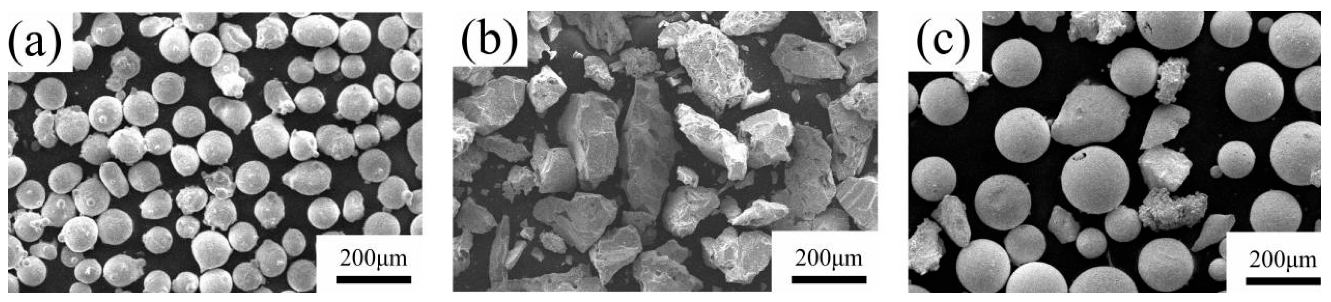
2.1. Raw Powder Preparation and Experimental Process

AlCoCrFeNi HEA powder with a purity of 99.99% and a size of 45–105 μm was used as the main coating powder. Various proportions of TiC/WC powder (not more than 30%) were used as the additive powder, and the three kinds of powders were stirred using a CZ0001 planetary ball mill for 2 h. Experiments were conducted on 100 mm × 50 mm × 3 mm 316Lss as a cladding substrate. The substrate was sanded with 400, 800, and 1200 mesh sandpaper to remove surface impurities and wear off the oxidized coating. After sanding, the substrate was wiped with anhydrous ethanol and then placed in a ventilated location for drying. The experiments were conducted after the completion of this treatment. The chemical compositions of 316Lss and AlCoCrFeNi HEA powders are listed in Table 1 and Table 2, respectively. Figure 1 shows the micrographs of the three powders under a scanning electron microscope (SEM). The AlCoCrFeNi HEA and WC powders were essentially spherical, whereas the TiC powder was block-shaped. The powder was dispersed, indicating that the powder was very dry.
HEA composite coatings with AlCoCrFeNi-TiC20−x/WCx (where the mass fraction in percent is x = 0, 5, 10, 15, and 20) composition were fabricated using laser cladding. Hereafter, the coatings containing different TiC/WC contents are defined as C–TiC0/WC0, C–TiC20/WC0, C–TiC15/WC5, C–TiC10/WC10, C–TiC5/WC15, and C–TiC0/WC20, respectively.

2.2. Methods

An XL-F2000W continuous laser system was used in this experiment. The wavelength of the laser was 1080 nm and its maximum power was 2000 W. The experiments were conducted by laying a powder with a thickness of 1 mm. After laying the powder, the experimental samples were preheated for 20 min until they were heated to 200 °C, and then the melting and cladding experiments were conducted. Preheating reduced the generation of thermal cracks in the samples during the melting and cladding processes [36]. Based on previous experimental experience, the pre-experiment, and observations of the forming state and connection of the interface between the substrate and coatings, we determined the following final experimental values: P = 1200 W, V = 16.7 mm/second, spot diameter = 3 mm, defocus = +3 mm, and overlap ratio = 40%. Cladding was performed in 12 tracks, and the cladding length of each pass was 40 mm.
The samples were cut to a standard size of 10 mm × 10 mm × 2 mm using an electric discharge machine wire cutter, which facilitated subsequent operations and testing. Then, the samples were inlaid using an epoxy resin metallographic cold inlay, which was configured according to a 10:8 ratio of inlay powder to liquid. After the inlay was completed, the sample was polished using sandpaper.

2.3. Test Methods

A Vickers hardness tester (MHVD-1000AT, Yizong Precision Instrument Co., Ltd., Shanghai, China) was used on the cross-sections for the cladding hardness test. The standard load value was 200 g, and the standard dwell time was 10 s. Horizontal tests were performed three times to obtain the average value. From the top to the bottom of the cladding coating, dots were made every 0.1 mm until the substrate was reached. A corresponding metallurgical etching solution was used to corrode the samples, after which the samples were rinsed with water, sprayed with alcohol, and then left to dry. After the samples were dried, cladding cross-sections of the transition zone were observed and photographed using an SEM (FEI, Quanta 250 FEG, Hillsboro, OR, USA). An X-ray diffractometer (XRD-6100, Shimadzu, Shimane-ken, Japan) was used to analyze the morphologies after the corrosion treatment. The voltage and current were set to 40 kV and 30 mA, respectively. K α rays from a Cu target in the range of 10°–90° were used for the diffraction measurements. Electrochemical corrosion was measured at 27 °C using an electrochemical workstation (CHI660E, Chen Hua Instruments, Shanghai, China), and the kinetic potential polarization curves as well as impedance diagrams of the samples were tested to further analyze the corrosion resistance of the samples. All the tests were repeated three times to ensure the reliability of the experimental data.

3. Results and Discussion

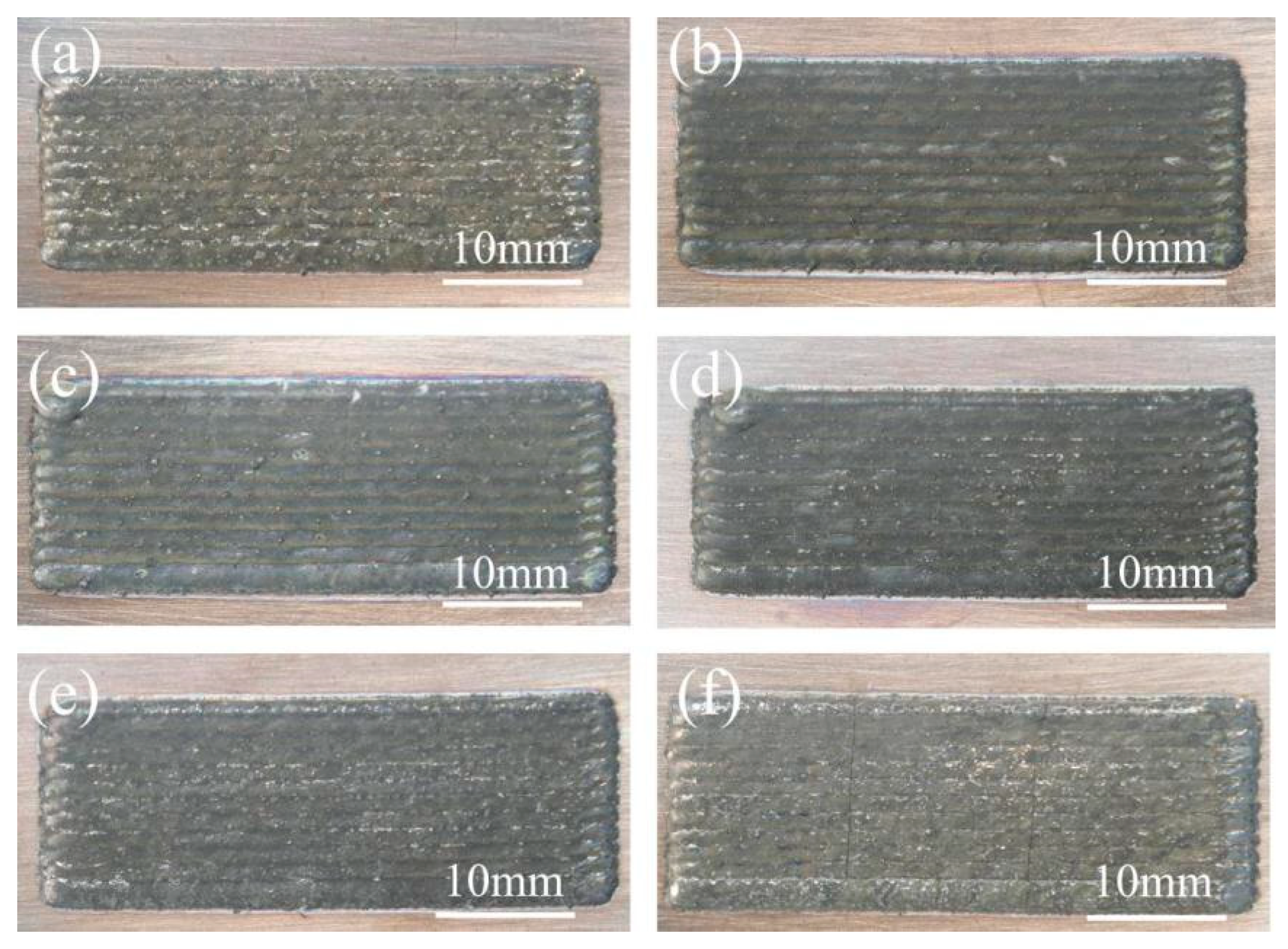
3.1. Macroscopic Morphology of the Coating

Figure 2 shows the macromorphology of the samples with the addition of C-TiC0/WC0, C-TiC20/WC0, C-TiC15/WC5, C-TiC10/WC10, C-TiC5/WC15, and C-TiC0/WC20, respectively. The surfaces of the C-TiC0/WC0, C-TiC20/WC0, C-TiC15/WC5, C-TiC10/WC10, and C-TiC5/WC15 were smooth, as shown in Figure 2a–e, whereas Figure 2f shows some cracks because of the higher content of WC. WC is a typical hard-reinforced phase, and WC powder affects the internal organizational structure of the powder and improves the hardness therein, leading to the generation of thermal cracks in the cladding coating during the cladding process [37,38]. In addition, the melting point of WC particles is very high, and they do not completely melt during laser cladding. The inclusion of WC particles in the solute causes the coating to dislocate and increases the internal stress of the coating. When the internal stress exceeds the critical value, the metal bond inside the coating breaks, which is macroscopically manifested as coating cracking.

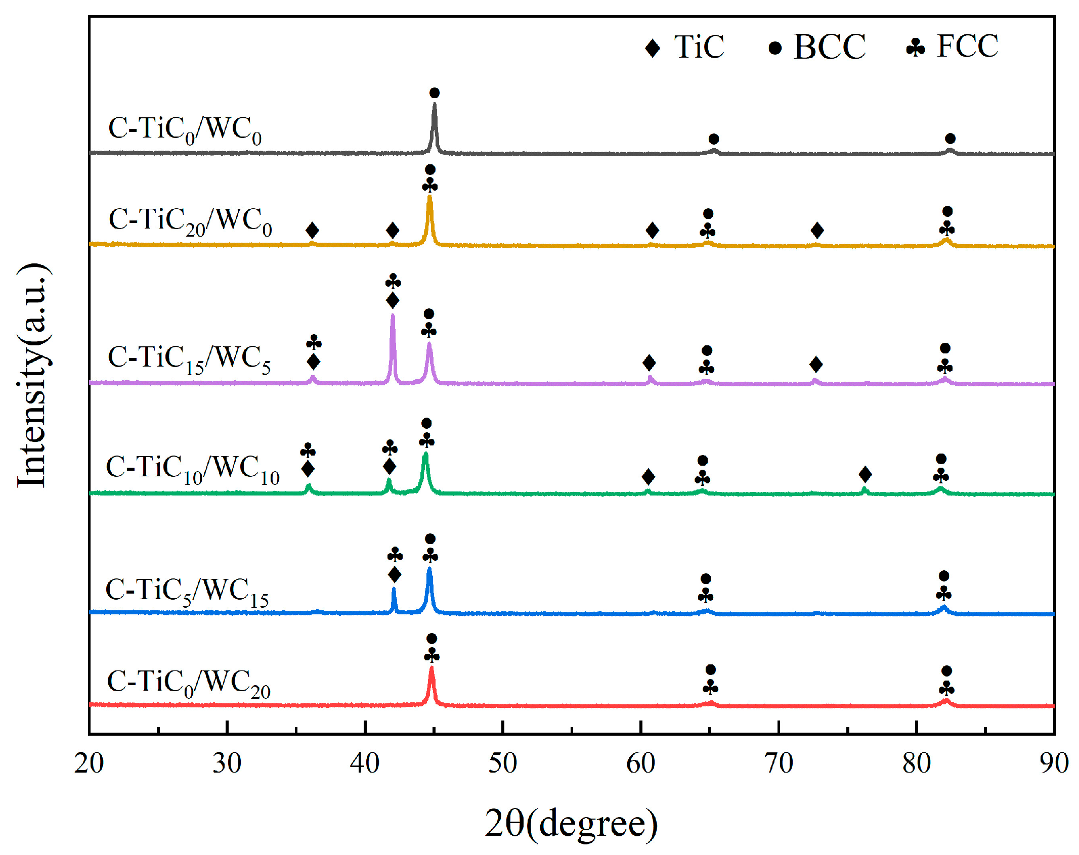
3.2. Phase Composition of the Coating

The C–TiC20−x/WCx coatings’ X-ray diffraction (XRD) results are shown in Figure 3. One can observe that C–TiC0/WC0 exhibits a simple BCC phase. It should be noted that the addition of TiC and WC powder causes the coatings to produce an FCC phase. However, the addition of WC and TiC did not produce too many complex phases of AlCoCrFeNi HEAs, which are mainly dominated by a simple BCC structure [39]. The phase and peak intensities formed by C–TiC0/WC0 and C–TiC0/WC20 are basically the same. It is well known that the height of the diffraction peaks is not only associated with the fraction of the phase but also associated with the texture. Although the TiC phase appeared in the C–TiC20/WC0, C–TiC15/WC5, and C–TiC10/WC10 coatings, it is difficult to judge the decomposition of TiC and the formation of other new phases simply from the height of the diffraction peaks [40]. In addition to the formation of other phases, the decrease in TiC content is also an important factor. When the amount of TiC added is 0, from C–TiC0/WC20, we can see that no TiC phase is produced. However, with the decrease in TiC content and the increase in WC content, no WC phase was found in the sample and no phases containing W and C elements were detected, which may be due to the gradual cladding of WC with other elements during the experiment to form other simple solid solution phases.

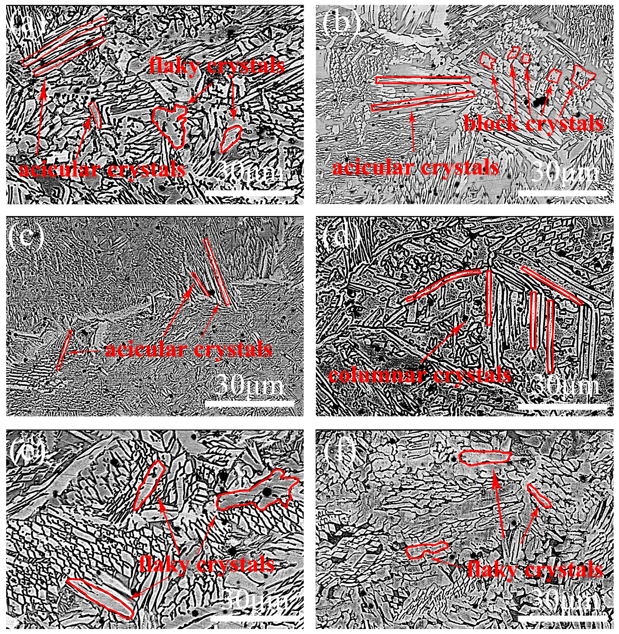
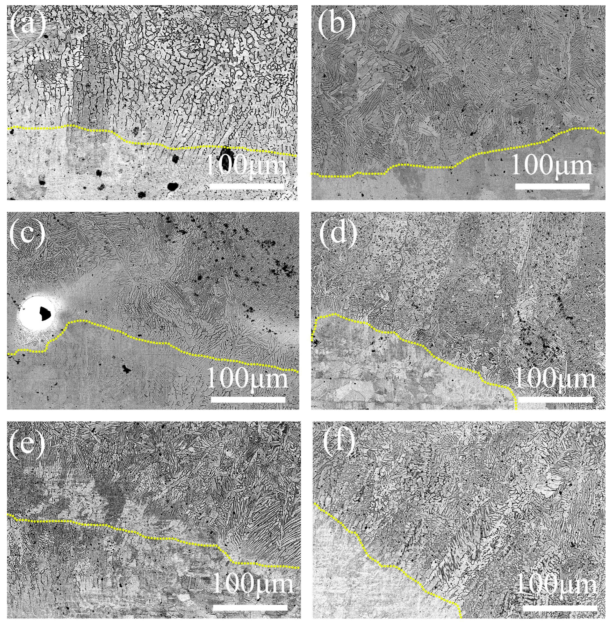
3.3. Microstructure of the Coating

Figure 4 shows the microstructural diagram of the top of the cladding coating. The addition of TiC and WC causes the crystal structure to change gradually. The longitudinal and transversal sections of Figure 4a can be seen as acicular and flaky crystals, and the acicular and block crystals are shown in Figure 4b. While the crystal structure is not obvious in Figure 4c, one can see a few acicular crystals only. With an increase in the WC mass fraction and a decrease in the TiC mass fraction, they form a competitive relationship for the formation of the crystal structure, which causes the crystal structure to change gradually [41]. Figure 4d shows the crystal structure with the same mass fractions of TiC and WC powders. At this time, dendrites are dominant, and there are a few cellular crystals. Subsequently, the mass fraction of WC gradually exceeds that of TiC, and the influence of TiC on the crystal structure is its main role. As the mass fraction of WC increases, along with the gradual decrease in the TiC mass fraction, the long columnar crystals gradually transform into flaky crystals and cell crystals, as shown in Figure 4e,f.
In order to analyze the grain size of different regions of the coating, typical C-TiC0/WC0 and C-TiC15/WC5 coatings were selected for comparison. Figure 5 shows the SEM image of the middle coatings of C-TiC0/WC0 and C-TiC15/WC5. First of all, in the same x coating, the crystal structure produced by the coating is basically the same. In Figure 5a,b, one can see that the coatings are mainly composed of acicular crystals and block crystals. In Figure 5c,d, one can see that the coatings are almost completely fine acicular crystals. This can explain the structural consistency of these coatings. Second, under the same x condition, the grain size of the upper layer is larger than that of the lower layer. According to the grain size evolution at different cooling rates [42], the cooling rate Rc determines the grain size. Rc is inversely proportional to the grain size. The larger the value of Rc, the smaller the grain size, and vice versa. The cooling rate in the middle of the cladding coating is higher than that at the top coating, so the grain size is relatively small. This is the reason why the grain size is different in different regions, and our result is also consistent with that of Shao et al. [42].
The micromorphology of the bottom of the samples is shown in Figure 6. In the vicinity of the yellow line, it is obvious that the coating and the substrate merge with each other to form a good transition zone; there are almost no cracks, pores, or other defects, and the metallurgical bonding is good [43], which also reflects the reasonableness of the laser process parameters in this experiment. Another noteworthy phenomenon is that the grain orientation at the bottom of the coating is relatively consistent, and the grain direction is perpendicular to the interface as a whole. This directionality is mainly caused by the formation of a micro-molten pool on the substrate caused by the laser, which reveals the direction of solidification in the process of rapid solidification.

3.4. Microhardness of the Coating

Microhardness is an important index to measure the mechanical properties of the coatings. Figure 7 shows the microhardness distribution of the coating cross-section from the top of the coating to the 316Lss substrate. This shows that there are three regions of microhardness of the cladding coatings, in which the microhardness of the substrate is the lowest and the hardness of the cladding coating is the highest. The microhardness of the heat-affected zone (HAZ) is between that of the substrate and that of the cladding coating. The main causes of microhardness delamination are that the average microhardness of 316Lss is 181 HV, and that of C-TiC0/WC0 is 532 HV, which is consistent with the results of previous works [44,45]. In the process of laser cladding, the mixtures around the melting pool are mixed, infiltrating with each other to form metallurgical bonding. Therefore, in terms of element distribution, the HAZ belongs to a transition zone that contains some elements of the 316Lss substrate and some elements of the cladding powder. Microhardness is closely related to the composition of elements, so it is not difficult to understand that the microhardness of the HAZ is between that of the substrate and that of the cladding coating. The top of the coating is mainly HEA powder and carbide, and its microhardness is higher.
However, one can see that the microhardness values of cladding coatings are much higher than that of the substrate, with a maximum increase of nearly a factor of 4. This increase is due to the hard TiC and WC powders, which improve the microhardness of the coatings. In all the coating samples, the coating average microhardness of C–TiC5/WC15 is the highest, reaching 664 HV, followed by C–TiC10/WC10 and C–TiC0/WC20 with high microhardness. It can be obviously seen that C–TiC0/WC0 does not contain any TiC/WC particles; consequently, its microhardness is relatively low.

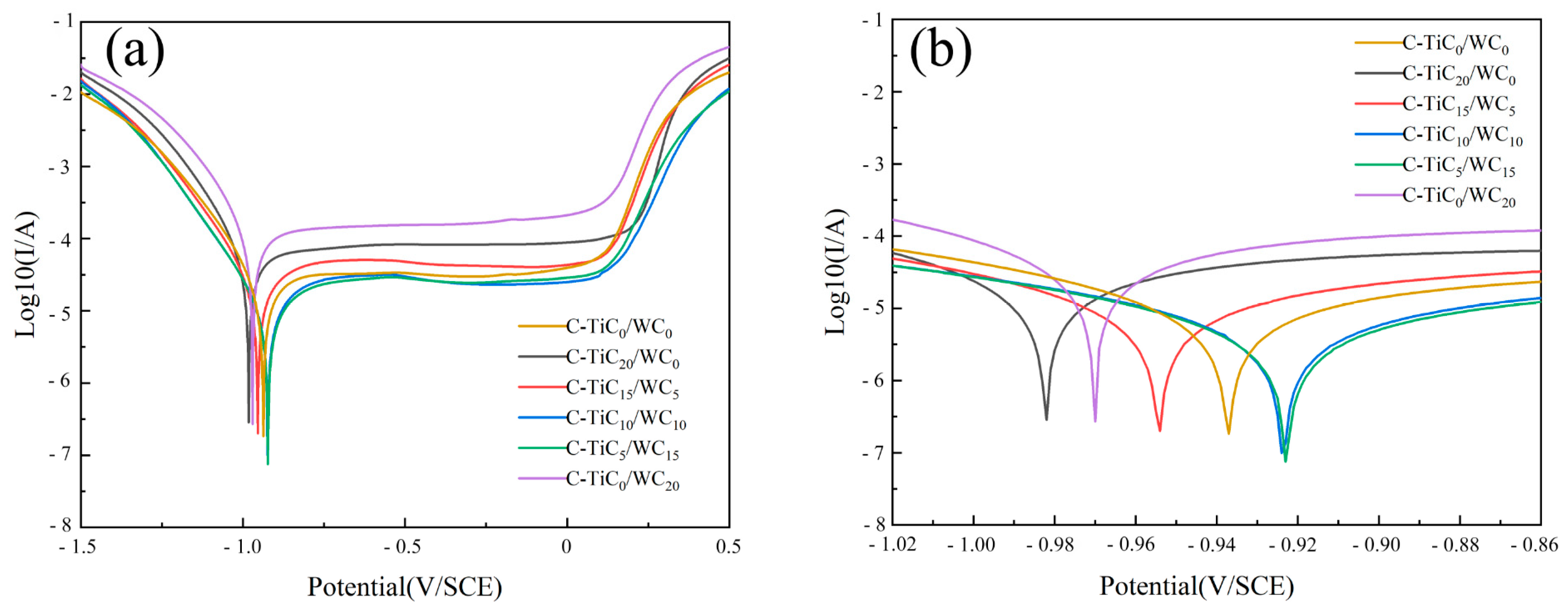
3.5. Corrosion Resistance of the Coating

Here, the Tafel curve is used to measure the corrosion resistance of the coatings. Figure 8 shows the Tafel polarization curves of the samples. One can see that the samples have different degrees of passivation and different passivation areas. A comparison of the corrosion voltages of the samples indicates that the corrosion voltages of C–TiC10/WC10 and C–TiC5/WC15 are closest to positive values, being −0.924 and −0.923 V, respectively, with the corrosion voltages of C–TiC5/WC15 being the closest, which proves that it has the best corrosion trend. The corrosion current density of the sample can be obtained by using the Tafel extrapolation method [46]. It is generally believed that the lower the corrosion current density, the slower the corrosion rate and the better the corrosion resistance [47]. As shown in Table 3, C–TiC5/WC15 has the lowest corrosion current density, which is mutually verified using its corrosion voltage, and it can be concluded that C–TiC5/WC15 has the best corrosion resistance among all the samples. In addition, one can also see that the corrosion trend of C–TiC20/WC0 is relatively poor, and its corrosion current density is the highest, thus C–TiC20/WC0 has the worst corrosion resistance. The figure also shows that the corrosion resistance of C–TiC0/WC20 is also not good, being the worst in addition to that of C–TiC20/WC0, which further demonstrates that the corrosion resistance of C–TiC5/WC15 is the best.
The corrosion resistance mechanism is analyzed in the following section. There are many factors that affect the corrosion resistance of HEA composite coatings, such as element content, chemical composition, and laser processing technology. Because the laser process parameters in this experiment are the same, the influence of the chemical composition and element distribution can be studied specifically. With the change in x, the corrosion resistance of the coating exhibits a trend of first increasing and then decreasing. This further demonstrates that the contents of WC and TC can affect the corrosion resistance of the coating. Electrochemical corrosion is essentially galvanic corrosion, with the element with a high corrosion potential in the coating acting as the cathode and that with a low corrosion potential acting as the anode, thus generating a corrosion current [44]. With an increase in x, the content of WC particles increases. WC particles exhibit ceramic properties and have excellent corrosion resistance, so they act as cathodes in the primary battery system, which improves the overall corrosion resistance of the coating. However, with a further increase in x, an increasing number of cathode elements leads to a larger cathode area, forming a large cathode–small anode model, which further reduces the corrosion resistance of the coating. In addition, the chemical composition can also affect the corrosion resistance of the coating. According to the XRD pattern (Figure 3), compared with the other x values, the diffraction peaks at 36° and 62° are particularly weak when x = 15. In this case, the chemical composition consists mainly of FCC and BCC phases, and the phase composition is relatively simple, which is beneficial for enhancing the corrosion resistance of the coating.

4. Conclusions

AlCoCrFeNi-TiC20−x/WCx HEA coatings (where the mass fraction x = 0, 5, 10, 15, and 20) were fabricated using laser cladding in this study. By optimizing the experimental parameters, cladding coatings with good metallurgical bonding were obtained. The effects of TiC and WC powders on the morphology, crystal structure, XRD patterns, microhardness, and corrosion resistance of the composite coatings were analyzed in detail. The main conclusions are as follows:
(1) The coating powders are fully melted, and their morphologies are relatively flat without obvious thermal cracks. The structure of the coatings is principally composed of the BBC phase, and the addition of TiC and WC powder causes the coating to form a new FCC phase. A change in x alters the coating morphology, ranging from columnar to flaky to irregular and cellular crystals.
(2) The average microhardness of the 316Lss substrate is 181 HV. The microhardness values of the coatings were a factor of ~4 higher than those of the substrate, which is due to the addition of hard TiC and WC powders. TiC and WC powders can enhance the microhardness of the coating. Among all coatings, the average microhardness of C–TiC5/WC15 is the highest, reaching 664 HV.
(3) The addition of TiC and WC powders can improve the corrosion resistance of the coatings. The mass fractions of TiC and WC in the powder have a competitive relationship with the corrosion resistance of the coating, with the corrosion resistance of the coating reaching an optimal value for C–TiC5/WC15.

Author Contributions

Conceptualization, Z.Z.; methodology, W.S.; software, J.H.; validation, W.S.; formal analysis, Z.Z.; investigation, W.S.; resources, J.H.; data curation, Z.Z.; writing—original draft preparation, J.H.; writing—review and editing, J.H.; visualization, W.S.; supervision, W.S.; project administration, J.H.; funding acquisition, J.H. All authors have read and agreed to the published version of the manuscript.

Funding

Supported by the National Natural Science Foundation projects (No. 62073089), the project of postgraduate demonstration courses (No. 2023SFKC_041). Date: 11 December 2023.

Data Availability Statement

The authors do not have permission to share data.

Conflicts of Interest

The authors declare no conflict of interest.

References

  1. Gu, D.D.; Meiners, W.; Wissenbach, K.; Poprawe, R. Laser additive manufacturing of metallic components: Materials, processes and mechanisms. Int. Mater. Rev. 2012, 57, 133–164. [Google Scholar] [CrossRef]
  2. Arif, Z.U.; Khalid, M.Y.; Rehman, E.U.; Ullah, S.; Atif, M.; Tariq, A. A review on laser cladding of high-entropy alloys, their recent trends and potential applications. J. Manuf. Process. 2021, 68, 225–273. [Google Scholar] [CrossRef]
  3. Yeh, J.W.; Chang, S.Y.; Hong, Y.D.; Chen, S.K.; Lin, S.J. Anomalous decrease in X-ray diffraction intensities of Cu-Ni-Al-Co-Cr-Fe-Si alloy systems with multi-principal elements. Mater. Chem. Phys. 2007, 103, 41–46. [Google Scholar] [CrossRef]
  4. Zhang, P.; Li, Z.; Liu, H.M.; Zhang, Y.B.; Li, H.X.; Shi, C.W.; Liu, P.; Yan, D.F. Recent progress on the microstructure and properties of high entropy alloy coatings prepared by laser processing technology: A review. J. Manuf. Process. 2022, 76, 397–411. [Google Scholar] [CrossRef]
  5. Yeh, J.W.; Chen, S.K.; Lin, S.J.; Gan, J.Y.; Chin, T.S.; Shun, T.T.; Tsau, C.H.; Chang, S.Y. Nanostructured high-entropy alloys with multiple principal elements: Novel alloy design concepts and outcomes. Adv. Eng. Mater. 2004, 6, 299–303. [Google Scholar] [CrossRef]
  6. Zhang, Y.; Zuo, T.T.; Tang, Z.; Gao, M.C.; Dahmen, K.A.; Liaw, P.K.; Lu, Z.P. Microstructures and properties of high-entropy alloys. Prog. Mater. Sci. 2014, 61, 1–93. [Google Scholar] [CrossRef]
  7. Zhang, H.; Liu, G.; Ren, N.N.; Cheng, N.; Dong, Z.X.; Ma, Q.S. Microstructure evolution and high temperature wear resistance of in-situ synthesized carbides reinforced NiCoFeCrSiMo high entropy alloy coatings fabricated by laser cladding. Surf. Coat. Technol. 2023, 464, 129573. [Google Scholar] [CrossRef]
  8. Li, W.D.; Xie, D.; Li, D.Y.; Zhang, Y.; Gao, Y.F.; Liaw, P.K. Mechanical behavior of high-entropy alloys. Prog. Mater. Sci. 2021, 118, 100777. [Google Scholar] [CrossRef]
  9. Li, Z.Z.; Zhao, S.T.; Ritchie, R.O.; Meyers, M.A. Mechanical properties of high-entropy alloys with emphasis on face-centered cubic alloys. Prog. Mater. Sci. 2019, 102, 296–345. [Google Scholar] [CrossRef]
  10. Guo, W.M.; Ding, N.; Liu, G.Q.; Jing, C.N.; Xu, H.X.; Liu, L.; Xu, N.; Wu, X.F.; He, J.Q.; Zaïri, F. Microstructure evolution of a multi-track AlCoCrFeNi high entropy alloy coating fabricated by laser cladding. Mater. Charact. 2022, 184, 111660. [Google Scholar] [CrossRef]
  11. Han, B.; Zhang, S.Y.; Zhang, T.M.; Chen, Y.H.; Qin, X.W.; Li, M.Y.; Hu, C.Y.; Wei, M.W.; Xue, X.X. Hardness enhancement mechanism of AlxCoCrFeNiSi high-entropy alloy coatings prepared by laser cladding. Intermetallics 2023, 158, 107909. [Google Scholar] [CrossRef]
  12. Shang, X.J.; Liu, Q.B.; Guo, Y.X.; Ding, K.L.; Liao, T.H.; Wang, F.P. Nano-TiC reinforced [Cr–Fe4Co4Ni4] Cr3 high-entropy-alloy composite coating fabricated by laser cladding. J. Mater. Res. Technol. 2022, 21, 2076–2088. [Google Scholar] [CrossRef]
  13. Han, B.; Chen, Y.B.; Tan, C.W.; Jiang, M.; Bi, J.; Feng, J.C.; Chen, X.; Chen, L.J.; Zhang, L.; Liu, X.G.; et al. Microstructure and wear behavior of laser clad interstitial CoCrFeNi high entropy alloy coating reinforced by carbon nanotubes. Surf. Coat. Technol. 2022, 434, 128241. [Google Scholar] [CrossRef]
  14. Wen, X.; Cui, X.F.; Jin, G.; Liu, Y.F.; Zhang, Y.; Zhang, X.R.; Liu, E.B.; Tian, H.L.; Fang, Y.C. Corrosion and tribo-corrosion behaviors of nano-lamellar Ni1.5CrCoFe0.5Mo0.1Nbx eutectic high-entropy alloy coatings: The role of dual-phase microstructure. Corros. Sci. 2022, 201, 110305. [Google Scholar] [CrossRef]
  15. Zhu, Q.; Liu, Y.; Zhang, C.Y. Laser cladding of CoCrFeNi high-entropy alloy coatings: Compositional homogeneity towards improved corrosion resistance. Mater. Lett. 2022, 318, 132133. [Google Scholar] [CrossRef]
  16. Li, H.G.; Huang, Y.J.; Jiang, S.S.; Lu, Y.Z.; Gao, X.Y.; Lu, X.; Ning, Z.L.; Sun, J.F. Columnar to equiaxed transition in additively manufactured CoCrFeMnNi high entropy alloy. Mater. Des. 2021, 197, 109262. [Google Scholar] [CrossRef]
  17. Wang, C.S.; Li, R.F.; Bi, X.L.; Yuan, W.Y.; Gu, J.Y.; Chen, J.; Yan, M.J.; Zhang, Z.Y. Microstructure and wear resistance property of laser cladded CrCoNi coatings assisted by ultrasonic impact treatment. Mater. Res. Technol. 2023, 22, 853–864. [Google Scholar] [CrossRef]
  18. Raahgini, C.; Verdi, D. Abrasive wear performance of laser cladded Inconel 625 based metal matrix composites: Effect of the vanadium carbide reinforcement phase content. Surf. Coat. Technol. 2022, 429, 127975. [Google Scholar] [CrossRef]
  19. An, X.L.; Liu, Q.B.; Zheng, B. Effect of Tungsten carbide on laser cladding of high entropy alloy. High Power Laser Part. Beams 2014, 26, 255–260. (In Chinese) [Google Scholar]
  20. Cai, Y.C.; Chen, Y.; Luo, Z.; Gao, F.; Li, L. Manufacturing of FeCoCrNiCux medium-entropy alloy coating using laser cladding technology. Mater. Des. 2017, 133, 91–108. [Google Scholar] [CrossRef]
  21. Qiu, X.W.; Liu, C.G. Microstructure and properties of Al2CrFeCoCuTiNix high-entropy alloys prepared by laser cladding. J. Alloys Compd. 2013, 553, 216–220. [Google Scholar] [CrossRef]
  22. Zhang, M.D.; Zhang, L.J.; Fan, J.T.; Li, G.; Liaw, P.K.; Liu, R.P. Microstructure and enhanced mechanical behavior of the Al7Co24Cr21Fe24Ni24 high-entropy alloy system by tuning the Cr content. Mater. Sci. Eng. A 2018, 733, 299–306. [Google Scholar] [CrossRef]
  23. Dong, Y.; Lu, Y.P.; Kong, J.R.; Zhang, J.J.; Li, T.J. Microstructure and mechanical properties of multi-component AlCrFeNiMox high-entropy alloys. J. Alloys Compd. 2013, 573, 96–101. [Google Scholar] [CrossRef]
  24. Quan, T.; Guo, W.B.; Qian, C. Study on Friction and Wear Properties of Powder Metallurgy Al1Co25Cr18Fe23Ni23Ta10 eutectic High Entropy alloy. J. Cem. Carbide 2018, 38, 156–164. (In Chinese) [Google Scholar]
  25. Liu, H.; Gao, Q.; Dai, J.B.; Chen, P.J.; Gao, W.P.; Hao, J.B.; Yang, H.F. Microstructure and high-temperature wear behavior of CoCrFeNiWx high-entropy alloy coatings fabricated by laser cladding. Tribol. Int. 2022, 172, 107574. [Google Scholar] [CrossRef]
  26. Jiang, Y.Q.; Li, J.; Juan, Y.F.; Lu, Z.J.; Jia, W.L. Evolution in microstructure and corrosion behavior of AlCoCrxFeNi high-entropy alloy coatings fabricated by laser cladding. J. Alloys Compd. 2019, 775, 1–14. [Google Scholar] [CrossRef]
  27. Zhao, S.L.; Xin, D.Q.; Chen, X.Z.; Stasic, J.; Trtica, M.; Siddiquee, A.N.; Mohan, S. Microstructure and enhanced tensile properties of AlCoxCrFeNi high entropy alloys with high Co content fabricated by laser melting deposition. J. Alloys Compd. 2022, 917, 165403. [Google Scholar] [CrossRef]
  28. Li, Z.T.; Jing, C.N.; Feng, Y.; Wu, Z.L.; Lin, T.; Zhao, J.R. Phase evolution and properties of AlxCoCrFeNi high-entropy alloys coatings by laser cladding. Mater. Today Commun. 2023, 35, 105800. [Google Scholar] [CrossRef]
  29. Akash, V.; Jyoti, M.; Harshad, N. Influence of WC particle on the metallurgical, mechanical, and corrosion behavior of AlFeCuCrCoNi-WCx high-entropy alloy coatings. J. Mater. Eng. Perform. 2021, 30, 2449–2461. [Google Scholar]
  30. Ma, Q.; Lu, B.W.; Zhang, Y.M.; Wang, Y.L.; Yan, X.C.; Liu, M.; Zhao, G.R. Crack-free 60 wt% WC reinforced FeCoNiCr high-entropy alloy composite coating fabricated by laser cladding. Mater. Lett. 2022, 324, 132667. [Google Scholar] [CrossRef]
  31. Li, L.Q.; Liu, D.J.; Chen, Y.B.; Wang, C.M.; Li, F.Q. Electron microscopy study of reaction layers between single-crystal WC particle and Ti–6Al–4V after laser melt injection. Acta Mater. 2009, 57, 3606–3614. [Google Scholar] [CrossRef]
  32. Yu, K.D.; Zhao, W.; Li, Z.; Guo, N.; Xiao, G.C.; Zhang, H. High-temperature oxidation behavior and corrosion resistance of in-situ TiC and Mo reinforced AlCoCrFeNi-based high entropy alloy coatings by laser cladding. Ceram. Int. 2023, 49, 10151–10164. [Google Scholar] [CrossRef]
  33. Wang, L.; Wang, L.; Tang, Y.C.; Luo, L.; Luo, L.S.; Su, Y.Q.; Guo, J.J.; Fu, H.Z. Microstructure and mechanical properties of CoCrFeNiWx high entropy alloys reinforced by μ phase particles. J. Alloys Compd. 2020, 843, 155997. [Google Scholar] [CrossRef]
  34. Poletti, M.G.; Fiore, G.; Gili, F.; Mangherini, D.; Battezzati, L. Development of a new high entropy alloy for wear resistance: FeCoCrNiW0.3 and FeCoCrNiW0.3 + 5 at.% of C. Mater. Des. 2017, 115, 247–254. [Google Scholar] [CrossRef]
  35. Chen, Y.H.; Sun, S.W.; Zhang, T.M.; Zhou, X.W.; Li, S.H. Effects of post-weld heat treatment on the microstructure and mechanical properties of laser-welded NiTi/304SS joint with Ni filler. Mater. Sci. Eng. A 2020, 771, 138545. [Google Scholar] [CrossRef]
  36. Fang, J.X.; Ma, G.Z.; Tian, H.L.; Li, S.B.; Huang, H.S.; Liu, Y.; Jiang, Y.L.; Liu, B. Transformation-induced strain of a low transformation temperature alloy with high hardness during laser metal deposition. J. Manuf. Process. 2021, 68, 1585–1595. [Google Scholar] [CrossRef]
  37. Wang, K.L.; Zhu, J.P.; Wang, H.L.; Yang, K.J.; Zhu, Y.M.; Qing, Y.B.; Ma, Z.; Gao, L.H.; Liu, Y.B.; Wei, S.H.; et al. Air plasma-sprayed high-entropy (Y0.2Yb0.2Lu0.2Eu0.2Er0.2)3Al5O12 coating with high thermal protection performance. J. Adv. Ceram. 2022, 11, 1571–1582. [Google Scholar] [CrossRef]
  38. Zhang, R.; Gu, X.Y.; Gong, H.T.; Gu, X.P.; Zhao, X.H. Effect of Nb content on microstructure and properties of FeCoNi2CrMnV0.5Nbx high-entropy alloy coatings by laser cladding. J. Mater. Res. Technol. 2022, 21, 3357–3370. [Google Scholar] [CrossRef]
  39. Li, Y.T.; Fu, H.G.; Ma, T.J.; Wang, K.M.; Yang, X.J.; Lin, J. Microstructure and wear resistance of AlCoCrFeNi-WC/TiC composite coating by laser cladding. Mater. Charact. 2022, 194, 112479. [Google Scholar] [CrossRef]
  40. Shen, L.; Zhao, Y.; Li, Y.L.; Wu, H.; Zhu, H.G.; Xie, Z.H. Synergistic strengthening of FeCrNiCo high entropy alloys via micro-TiC and nano-SiC particles. Mater. Today Commun. 2021, 26, 101729. [Google Scholar] [CrossRef]
  41. Hemmati, I.; Ocelik, V.; Csach, K.; de Hosson, J.T.M. Microstructure and Phase Formation in a Rapidly Solidified Laser-Deposited Ni-Cr-B-Si-C Hardfacing Alloy. Metall. Mater. Trans. A 2014, 45, 878–892. [Google Scholar] [CrossRef]
  42. Shao, J.Y.; Yu, G.; He, X.L.; Li, S.X.; Chen, R.; Zhao, Y. Grain size evolution under different cooling rate in laser additive manufacturing of superalloy. Opt. Laser Technol. 2019, 119, 105662. [Google Scholar] [CrossRef]
  43. Huang, J.; Zhu, Z.K.; Wang, H.; Li, K.Y.; Shi, W.Q.; Jiao, T.W. Effect of WC Content on Microstructure and Properties of CoCrFeNi HEA Composite Coating on 316L Surface via Laser Cladding. Materials 2023, 16, 2706. [Google Scholar] [CrossRef]
  44. Luo, F.Y.; Shi, W.Q.; Xiong, Z.Y.; Huang, J. Microstructure and properties analysis of AlCoCrFeNi high-entropy alloy/iron-based amorphous composite coatings prepared by laser cladding. J. Non-Cryst. Solids 2024, 624, 122732. [Google Scholar] [CrossRef]
  45. Huang, J.; Zhu, Z.K.; Li, K.Y.; Shi, W.Q.; Zhao, Y.; He, M.Y. Microstructures and Mechanical Properties of an AlCoCrNiFe HEA/WC Reinforcing Particle Composite Coating Prepared by Laser Cladding. Materials 2022, 15, 8020. [Google Scholar] [CrossRef] [PubMed]
  46. Wang, H.; Li, Y.; Cheng, G.; Wu, W.; Zhang, Y. A study on the corrosion behavior of carbon steel exposed to a H2S-containing NH4Cl medium. J. Mater. Eng. Perform. 2018, 27, 2492–2504. [Google Scholar] [CrossRef]
  47. Modupeola, D.; Patricia, P.; Ntombi, M.; Sisa, P.; Samson, A.; Olufemi, A. The comparative study of the microstructural and corrosion behaviour of laser-deposited high entropy alloys. J. Alloys Compd. 2021, 866, 158777. [Google Scholar]
Figure 1. SEM image of powder: (a) AlCoCrFeNi; (b) TiC; (c) WC.
Crystals 14 00083 g001
Figure 2. Coating macroscopic topography: (a) C-TiC0/WC0; (b) C-TiC20/WC0; (c) C-TiC15/WC5; (d) C-TiC10/WC10; (e) C-TiC5/WC15; (f) C-TiC0/WC20.
Crystals 14 00083 g002
Figure 3. X-ray diffraction of the samples.
Crystals 14 00083 g003
Figure 4. SEM image of the coating top: (a) C-TiC0/WC0; (b) C-TiC20/WC0; (c) C-TiC15/WC5; (d) C-TiC10/WC10; (e) C-TiC5/WC15; (f) C-TiC0/WC20.
Crystals 14 00083 g004
Figure 5. SEM image comparison of the middle and top regions of the coating: (a) C-TiC0/WC0 of the coating middle region; (b) C-TiC0/WC0 of the coating top region; (c) C-TiC15/WC5 of the coating middle region; (d) C-TiC15/WC5 of the coating top region.
Crystals 14 00083 g005
Figure 6. SEM image of the coating bottom: (a) C-TiC0/WC0; (b) C-TiC20/WC0; (c) C-TiC15/WC5; (d) C-TiC10/WC10; (e) C-TiC5/WC15; (f) C-TiC0/WC20.
Crystals 14 00083 g006
Figure 7. The microhardness characteristics of C-TiC0/WC0, C-TiC20/WC0, C-TiC15/WC5, C-TiC10/WC10, C-TiC5/WC15, and C-TiC0/WC20 coatings, respectively.
Crystals 14 00083 g007
Figure 8. (a) Potentiodynamic polarization diagram of HEA/TiC + WC composite coatings; (b) partially enlarged potentiodynamic polarization diagram.
Crystals 14 00083 g008
Table 1. Chemical composition of 316Lss (mass fraction, %).
CrNiMnMoSiFe
16–1810–1422–31.5Bal.
Table 2. Chemical composition of AlCoCrFeNi HEAs powders (mass fraction, %).
AlCoCrFeNi
11.0923.3420.1921.7223.53
Table 3. Electrochemical parameters of AlCoCrFeNi HEAs + TiC + WC.
MaterialsEcorr (V/SCE)Icorr (A/cm2)
C-TiC0/WC0−0.9371.831 × 10−7
C-TiC20/WC0−0.9822.848 × 10−7
C-TiC15/WC5−0.9542.006 × 10−7
C-TiC10/WC10−0.9249.874 × 10−8
C-TiC5/WC15−0.9237.508 × 10−8
C-TiC0/WC20−0.9702.695 × 10−7
Disclaimer/Publisher’s Note: The statements, opinions and data contained in all publications are solely those of the individual author(s) and contributor(s) and not of MDPI and/or the editor(s). MDPI and/or the editor(s) disclaim responsibility for any injury to people or property resulting from any ideas, methods, instructions or products referred to in the content.

