Abstract
In this study, trace amounts of In and Ce elements were composite added into a Ag10CuZnSn low-silver brazing filler metal, and the effects of the composite alloying on the solidus and liquidus temperatures, the spreading performance, the microstructure of the filler metal, and the mechanical properties of the joints prepared with these filler metals were studied. The results reveal that the In element can significantly decrease the solidus and the liquidus temperatures of the Ag10CuZnSn alloy, while the Ce element has little effect on the melting temperature. Trace amounts of In and Ce elements can obviously increase the spreading areas of the filler metals on the pure Cu and 304 stainless steel base metals. The In and Ce elements can refine the microstructure of the filler metals. When the contents of In and Ce are 1.5 wt% and 0.15 wt%, respectively, the microstructure refinement effect is the most obvious, and the shear strength of the 304 stainless steel brazed joint also achieves a maximum value of 375 MPa. Excessive addition of In and Ce can form brittle intermetallic compounds in the filler metal, decreasing the brazed joints' shear strength.
1. Introduction
Due to their relatively low melting point, superior wetting and spreading performance on most metals and alloys, high mechanical properties, and good electrical and thermal conductivities, the Ag-based brazing filler metals have been used in the fields of aerospace, household appliances, the automotive industry, refrigeration valves, hardware products, the military industry, and so on [1,2]. Among them, the AgCuZnCd series brazing filler metals have the best brazeability and can be used to braze nearly all ferrous and non-ferrous metals [3]. The Cd element can not only decrease the melting point and the melting temperature range of the AgCuZn filler metals, but also improve their wetting and spreading performances [4]. At the same time, it has been found that the Cd element is highly toxic to humans [5,6]. The smoke generated by the Cd-containing filler metals during the brazing operation can be easily inhaled by humans, which seriously damages the health of the brazing operators and limits the application of the AgCuZnCd filler metals [7]. In fact, the application of Cd-containing filler metals has been forbidden by the RoHS directive. The high price of silver also restricts the wider application of Ag-based brazing filler metals. Therefore, optimizing the melting characteristics, wettability, and mechanical properties of the low-silver Cd-free brazing filler metals to meet the application requirements has become a relevant and difficult problem.
Recently, researchers mainly improve the performance of the low-silver filler metals through “microalloying” [8], i.e., improving the performance of the filler metal by adding a small amount of an alloy element into a base filler metal. Based on the most widely used AgCuZn or AgCuZnSn low-silver filler metals, trace amounts of beneficial elements such as Ga, In, Mn, Ni, Li, and rare earth elements (RE) have been added to optimize the melting temperature, spreading performance, microstructure, and mechanical properties, to obtain low-silver filler metals with comparable properties to the traditional high-silver brazing filler metals [9]. It was found that a low melting point element such as Ga and In can decrease the melting temperatures and optimize the mobility and spreadability of the Ag-based brazing filler metals [10]. The Mn and Ni element can improve the strength of the brazing filler metals and the brazed joints, while the added amount should be relatively high, which may increase the melting temperature and decrease some other properties of the filler metals [11]. The RE is known as “industrial vitamins”, and adding trace amounts of RE can significantly improve various properties of the filler metals [12]. Moreover, composite alloying has been considered to be a more efficient method to optimize the brazing filler metals with the same content of the alloy element [13] because the beneficial effects of each element have a marginal effect, i.e., with increasing content of the alloy element, an increased rate of the “beneficial effect” decreases or even becomes negative. Therefore, the composite addition of trace amounts of alloy elements will be an efficient method to optimize the brazing filler metals.
For the reasons above, in this study, trace amounts of In and Ce elements were added to a low-silver filler metal to optimize its performance. The In rather than Ga was chosen because the annual output of In is twice that of Ga; thus, the price of In is relatively low, and the melting point of In is only 156.61 °C. An appropriate amount of In can dissolve into the Ag and Cu substrates and decrease the melting temperature of the filler metal [14]. The Ce element is a commonly used rare earth element in the alloy industry and has been used to optimize the Ag-based brazing filler metal [15]. The In element and the rare earth element Ce were composite added into the Ag10CuZnSn low-silver filler metal, and the combined effects of the different contents of In and Ce on the melting characteristics, spreading performance, microstructure of the filler metal, and mechanical properties of the brazed joints were investigated. It is hoped that this work can provide some basis for the development of new low-silver filler metals and also for engineering applications.
2. Materials and Methods
The Ag10CuZnSn-xIn-yCe low-silver brazing filler metals used in this study were smelted using a medium-frequency furnace with a frequency of 600 Hz and a power of 50 kW. The raw materials were Ag ingots, Zn ingots, Sn ingots, and In blocks with a purity of 99.99%, Cu-Ce intermediate alloy with a measured Ce content of 20.06 wt%, and electrolytic Cu plates with a purity of 99.9%. To decrease the burning loss of the raw materials, borax was used as the covering agent during the smelting process. After all, the alloys were melted and the slag was removed, ingots with a diameter of 50 mm were obtained by pouring the liquid alloys into a steel mold. Then, the surface of the ingots was mechanically cleaned (peeling and polishing), the ingots were hot extruded into a wire embryo with a diameter of 2.5 mm, and the filler metal wires with a diameter of 2.0 mm were prepared through acid washing, drawing, and straightening. Chemical compositions of the filler metals were characterized by inductively coupled plasma spectrometer (ICP, ICAP6300R) (PerkinElmer, Massachusetts, America.) and are shown in Table 1. The relative error between the actual contents and the theoretical addition amount of the alloy elements (Ag, Cu, Zn) is within ±0.05 wt%, the contents of Sn and In are within ±0.1 wt%, and the content of Ce is within ±0.2 wt%. Therefore, it can be concluded that the composition of the filler metals has been precisely controlled.

Table 1.
Chemical compositions of the Ag10CuZnSn-xIn-yCe low-silver filler metals.
A differential thermal analyzer (DTA, HCR-1) (HENVEN, Beijing, China) was used to measure the melting behaviors of the low-silver filler metals. The nitrogen flow rate and heating rate are 200 mL/min and 10 °C/min, respectively, and the test temperature range is 25 °C~900 °C. The pure Cu and 304 stainless steel plates used for spreading tests were cut into 40 mm × 40 mm × 2 mm pieces, and the surface of the test plates was ground with sandpaper to remove the oxide film. The spreading test was carried out according to the Chinese National Standard GB/T 11364-2008 “Test Method for Wettability of Filler Metals” [16]. The filler metal samples weighed 0.2 g and were placed at the center of the base metal plates, covered with the FB102 flux, and kept for 60 s in a furnace at a temperature of 850 °C. After cooling, the specimens were cleaned, and the spreading areas of the filler metals were calculated using Image-Pro Plus software. To ensure accuracy, 5 parallel tests were conducted for each group of filler metals to arrive at an average value of the wetting area.
To observe the microstructure, the low-silver filler metals were cut, embedded, mechanically ground, polished and then corroded with a H2O (100 mL) + (NH4)2S2O8 (15 g) + NH3·H2O (2 mL) solution to prepare the metallographic samples, and the corrosion time was 8 s. Microstructures of the specimens were observed with a field emission Scanning Electron Microscope (SEM, ZEISS ΣIGMA 500), and compositions of the phases in these filler metals were characterized by the Energy Dispersive Spectrometer (EDS, Bruker Nano X-Flash Detector 5010) (Bruker, Massachusetts, America.) equipped on the SEM under the point analysis and mapping mode.
The Cu and 304 stainless steel plates used to prepare the shear test specimens were cut into sizes of 80 mm × 25 mm × 2 mm, and the overlap length was 2 mm. The flame brazing method was used in this study to prepare the shear specimens. The substrate plates were lapped and fixed with a clamping apparatus and then heated to a temperature of about 850 °C by an oxyhydrogen flame. The filler metal wires were dipped into the FB102 flux and then put into contact with the substrate plates to melt the filler metal and fill the seam. A shear test of the brazed joints was conducted in accordance with the Chinese National Standard GB/T 11363-2008 “Test Methods for Strength of Brazed Joints” [17]. An electronic universal tensile testing machine (SANS-CMT5105, MTS) was used to test the shear strength of the Cu/304 stainless steel lap joints and the 304 stainless steel lap joints. The loading rate was 5 mm/min, and each group of the brazed joints was tested 5 times to obtain an average shear strength. After that, the fracture morphologies of the shear specimens were observed by the SEM (ZEISS, Oberkochen, Germany.).
3. Results and Discussion
3.1. Melting Characteristics of the Ag10CuZnSn-xIn-yCe Filler Metals
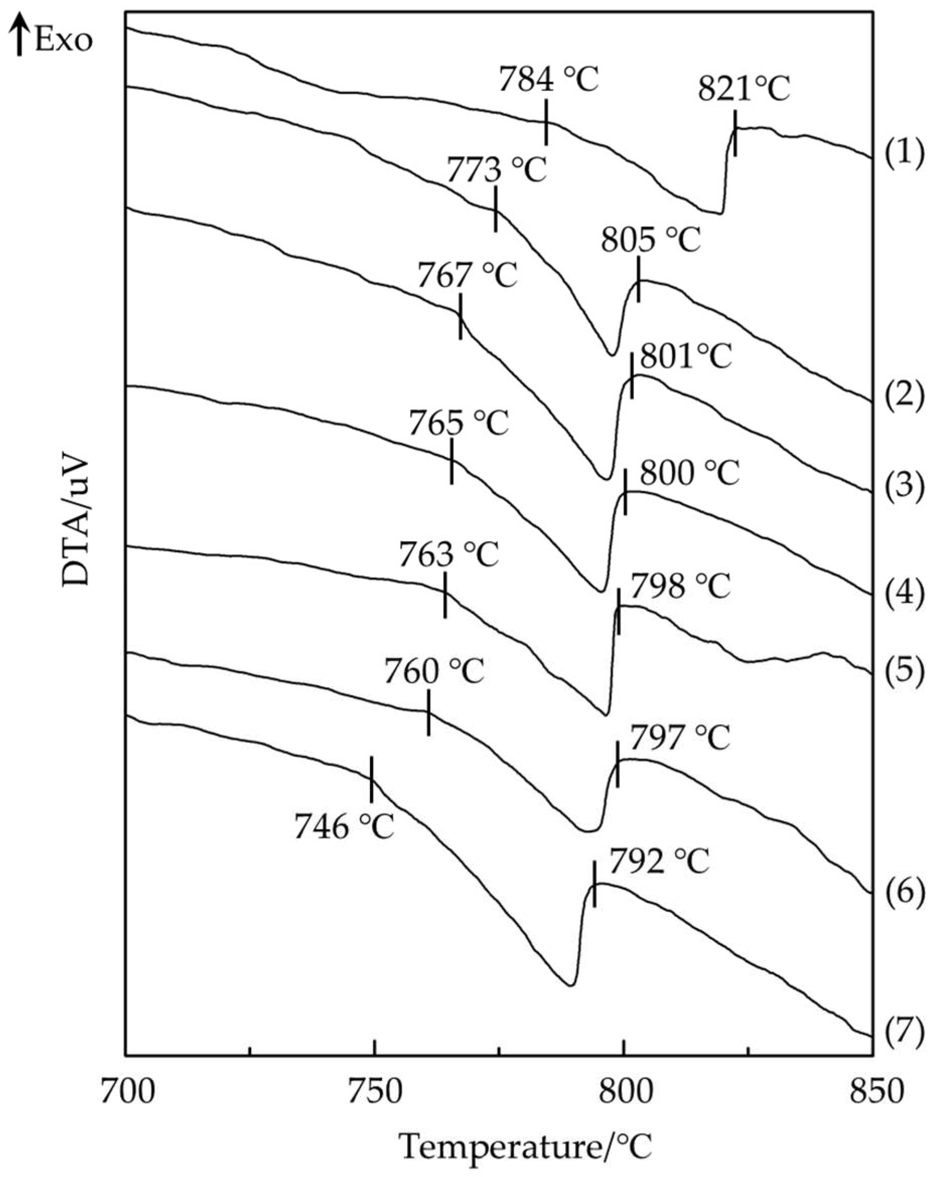
The solidus and liquidus temperatures of the Ag10CuZnSn-xIn-yCe filler metals with different contents of In and Ce are shown in Figure 1. From the melting temperature variation of the filler metals No. 3 to No. 6, it can be seen that when the content of In is 1.5 wt%, the solidus and liquidus temperatures show only a slight decrease as the Ce content increases from 0.05 wt% to 0.5 wt%, indicating that the effect of the trace Ce element on melting temperature of the filler metal is relatively small because the content of Ce is low Its melting point is close to the melting temperature of the Ag10CuZnSn alloy, which consists of the effect of the Ce element on the melting temperature of the Ag30CuZnSn alloy [11].
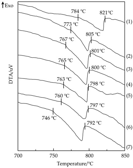
Figure 1.
Solidus and liquidus temperatures of the Ag10CuZnSn-xIn-yCe low-silver filler metals: (1) Ag10CuZnSn; (2) Ag10CuZnSn-1In-0.05Ce; (3) Ag10CuZnSn-1.5In-0.05Ce; (4) Ag10CuZnSn-1.5In-0.15Ce; (5) Ag10CuZnSn-1.5In-0.3Ce; (6) Ag10CuZnSn-1.5In-0.5Ce; (7) Ag10CuZnSn-3In-0.5Ce.
By comparing the No. 2 and No. 3 alloys to the No. 6 and No. 7 alloys, it can be found that both the solidus and liquidus temperatures decrease when the content of Ce remains constant and the content of In increases because the melting temperature of the In element is very low and its effect to decrease the melting point is significant. When the content of In is 3 wt%, and the content of Ce is 0.5 wt%, the solidus and liquidus temperatures of the filler metal decrease to 746 °C and 792 °C respectively, indicating that the decrease in the melting temperature of the filler metal is due mainly to the addition of In.
3.2. Spreadability of the Ag10CuZnSn-xIn-yCe Filler Metals
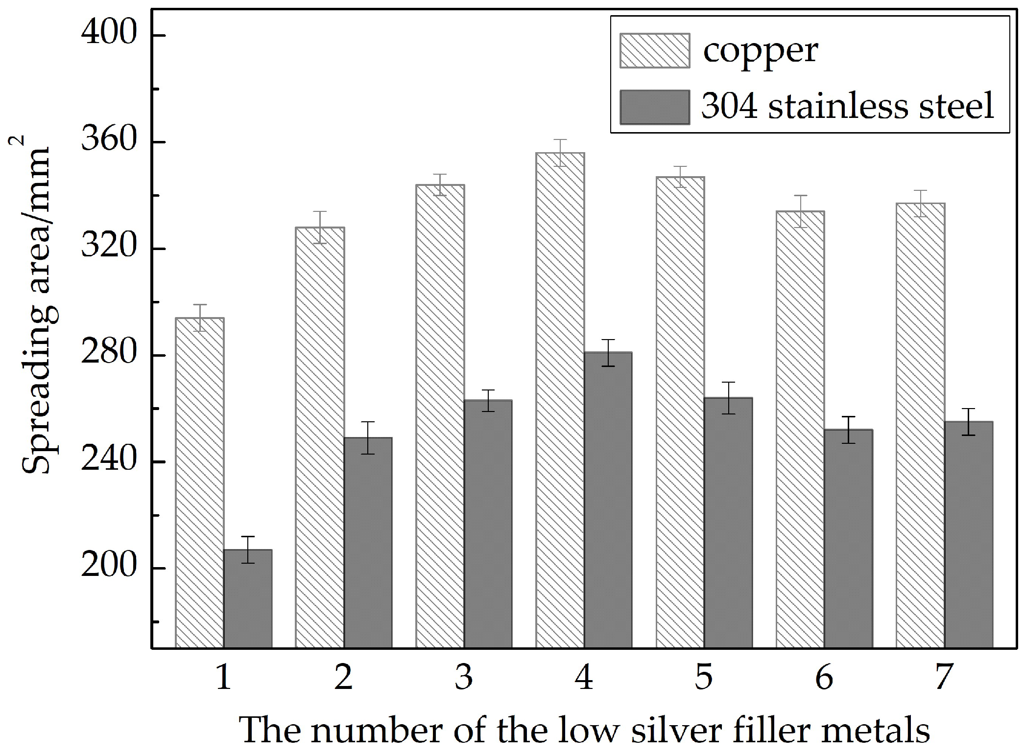
The spreading areas of the Ag10CuZnSn-xIn-yCe filler metals on the Cu and 304 stainless steel plates are shown in Figure 2, and it is clear that the composite addition of trace amounts of In and Ce can improve the spreading areas of the filler metal on the two base materials. Comparing the No. 2 and No. 3 alloys to the No. 6 and No. 7 alloys, it can be seen that when the content of Ce remains constant, the spreading area increases gradually with an increase in the In content. As mentioned before, the In element can significantly decrease the melting temperature of the Ag10CuZnSn filler metal. At the same brazing temperature, the filler metals with lower melting temperatures will have a greater superheat degree, lower viscosity and higher flowability; thereby, the spreading area can be increased.
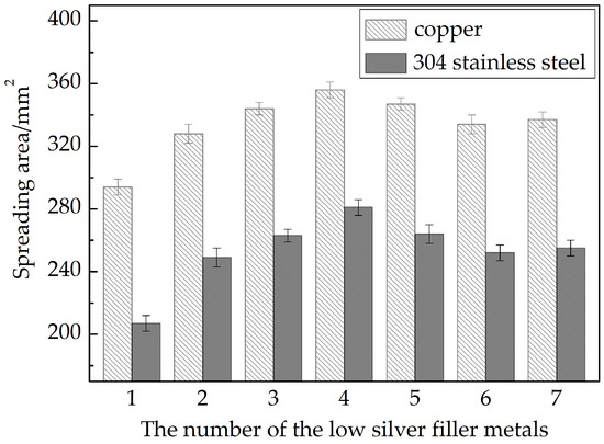
Figure 2.
Spreading areas of the Ag10CuZnSn-xIn-yCe low-silver filler metals on the Cu plates and the 304 stainless steel plates.
When the content of In is 1.5 wt%, the spreading areas increase continuously with increasing Ce content, and the spreading areas reach their maximum values when the Ce content is 0.15 wt%. They are 356 mm2 on the Cu and 281 mm2 on the 304 stainless steel, respectively, which are 21.1% and 35.7% higher than that of the Ag10CuZnSn base alloy. This is because the Ce is chemically active and can preferentially react with the oxygen to form a rare earth oxide that floats on the surface of the liquid brazing filler metal, which purifies the filler metal melt, decreases the surface tension, and separates the liquid alloy from the air, thereby improving the spreading performance of the filler metal. However, when the content of Ce is higher, the spreading areas begin to decrease because the excessive Ce can form a large amount of oxide slag that aggregates at the forefront of the liquid alloy and hinders its spreading on the substrate plate [15]. Thus, the addition of Ce should not be too high. If the flux can better prevent oxidation, the addition of the Ce element might be higher.
3.3. Microstructures of the Ag10CuZnSn-xIn-yCe Filler Metals
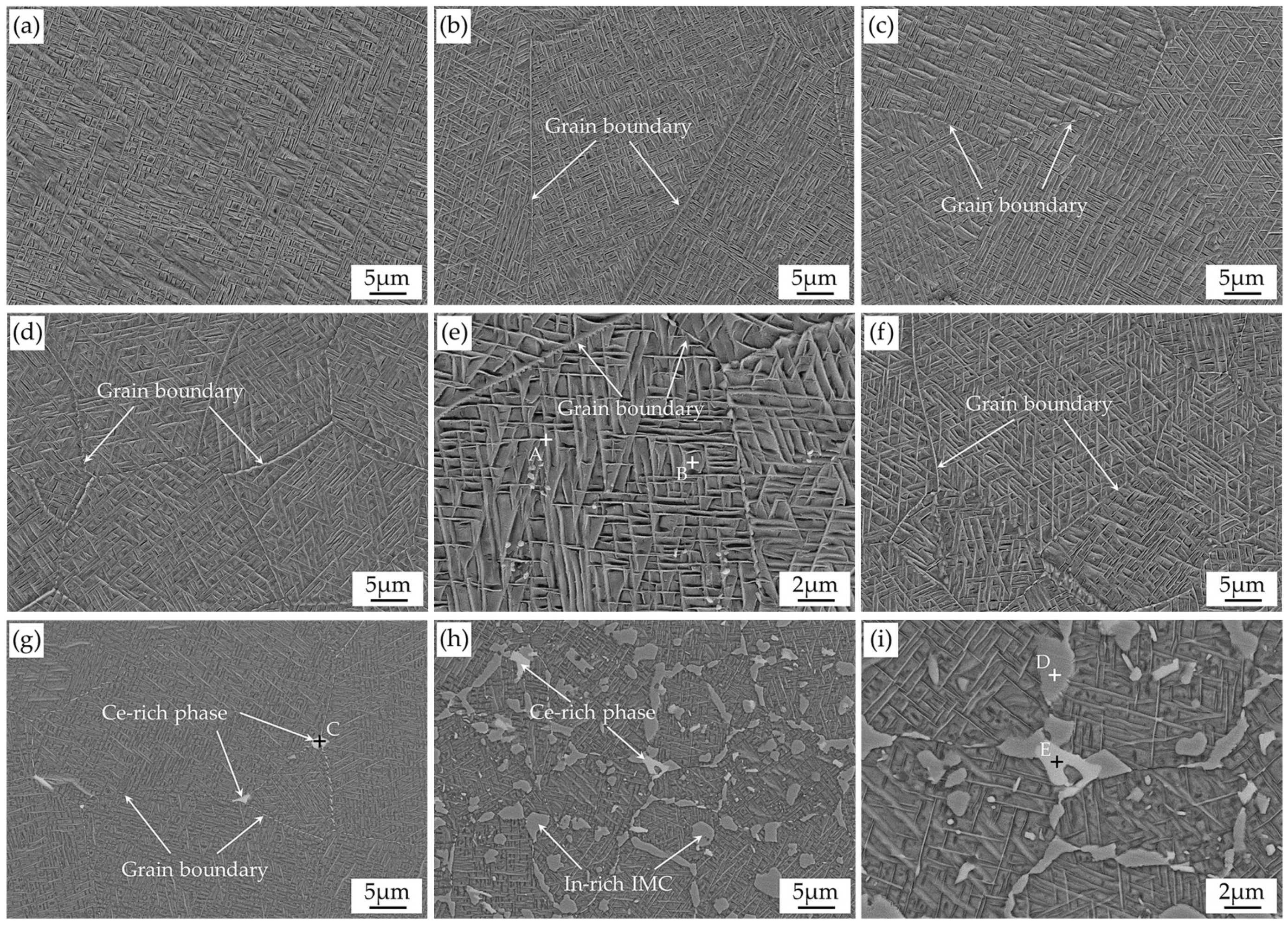
Figure 3 shows the microstructure of the Ag10CuZnSn-xIn-yCe filler metals, and the EDS analysis results of the points A~E in Figure 3e,g,i are presented in Table 2. From the figures, it can be clearly seen that the Ag10CuZnSn filler metal has a network microstructure, and the microstructure changes gradually with the increasing contents of the In and Ce elements. It has been revealed that the microstructure of the AgCuZnSn alloy with low-silver content is mainly composed of a Cu-based solid solution substrate, an acicular Ag-based solid solution, and a few CuZn compounds [18]. Based on that, it can be inferred from Figure 3a–e and the EDS results in Table 2 that the white acicular phase is the Ag-based solid solution (point A). The contents of In and Sn in this phase are high because In has a solubility of about 20%, and Sn has a solubility of about 10% in the Ag matrix at room temperature. The gray matrix is the Cu-based solid solution (point B), while no obvious CuZn compound phase was found in the filler metals.
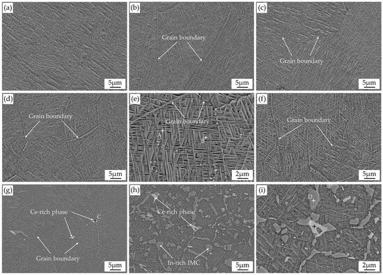
Figure 3.
Microstructures of the Ag10CuZnSn-xIn-yCe low-silver filler metals: (a) Ag10CuZnSn, (b) Ag10CuZnSn-1In-0.05Ce, (c) Ag10CuZnSn-1.5In-0.05Ce, (d) Ag10CuZnSn-1.5In-0.15Ce, (e) Ag10CuZnSn-1.5In-0.15Ce (higher magnification), (f) Ag10CuZnSn-1.5In-0.3Ce, (g) Ag10CuZnSn-1.5In-0.5Ce, (h) Ag10CuZnSn-3In-0.5Ce, (i) Ag10CuZnSn-3In-0.5Ce (higher magnification).
Table 2.
Chemical compositions of points A~E in Figure 3 characterized by EDS.
From the microstructure shown in Figure 3a–c, it can be inferred that a trace amount of additional In has little effect on the microstructure of the filler metal. When the content of In is 1.5 wt%, the grain size of the filler metal becomes smaller, and the microstructure is more uniform as the Ce content increases, as presented in Figure 3c–g. The reason is that the In element can dissolve into the Ag-based solution and a little in the Cu-based solid solution. Thus, it will decrease the melting temperature but not affect the microstructure. When the additional amounts of In and Ce are 1.5 wt% and 0.15 wt%, respectively, the grain size is only about 15 μm, and the uniform and fine grains can simultaneously improve the strength and plasticity of the filler metal [19]. Compared with the elements in the Ag10CuZnSn alloy, the Ce element has a larger atomic radius, a different crystal structure, and a large difference in electronegativity. Therefore, the Ce element can hardly dissolve into the alloy and concentrates as fine particles at the front of the solid–liquid interfaces. Consequently, it can act as a nucleation core during the solidification process and improves the nucleation rate. Meanwhile, it can hinder the continuous growth of the grains, decrease the growth rate of dendrites, and thus significantly refine the microstructure of the filler metals, whereas the microstructure of the filler metal was not further refined with higher Ce content. When the content of Ce reaches 0.5 wt%, a white block or strip-like phases appear at the grain boundaries (see Figure 3i). The EDS results reveal that the white phase contains 24.69 wt% of Ce, 29.37 wt% of Sn, and 31.15 wt% of Cu, so it can be preliminary inferred that it is a Ce-rich phase. When the contents of In and Ce are 3 wt% and 0.5 wt%, respectively, abundant white phases and a new gray phase appear, and EDS analysis shows that the content of In in the gray phase is 8.23 wt%, so it is preliminarily inferred to be an In-rich intermetallic compound (IMC) or solid solution [20]. In an In-rich phase with Ag and Cu, the IMCs such as Ag3(Sn,In), Cu6(Sn,In)5, Cu3(Sn,In), and Cu2(In,Sn) might be formed [21,22,23,24], while this needs to be further revealed.
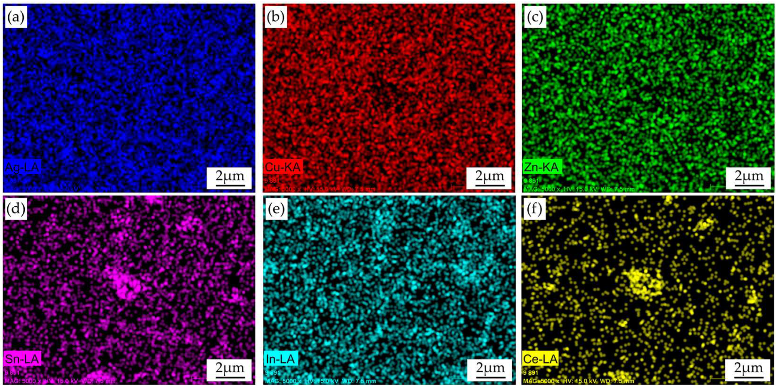
As the point analysis results of a particle are affected by the surrounding elements, EDS mapping was conducted in Figure 3i, and Figure 4 shows the element distribution of Ag10CuZnSn-3In-0.5Ce alloy shown in Figure 3i. It can be clearly seen that the distributions of Sn and Ce overlap with the white phase, and the contents of the other elements in the white phase are low. According to the point analysis result of point E in Figure 3i and the Sn-Ce phase diagram and composition of point E in Figure 3, it is predicted that the Sn-Ce phase should be Ce2Sn3. Moreover, the distribution of the In elements overlaps with the gray phase. When the content of In is high (3 wt%), it cannot fully dissolve into the Ag matrix and the Cu matrix. Meanwhile, the In has a much lower melting point; thus, it tends to concentrate at the front of the solid–liquid interface during the crystallization process, and finally solidifies at the grain boundary to form the In-rich phase. Wu et al. [25] found that Cu4In and Ag9In4 IMCs appeared in Ag12CuZnSn-5In brazing filler metal. Therefore, there was a sufficient basis to infer that the In-rich phase in this paper was mixed IMCs of Cu4In and Ag9In4. A more Ce-rich phase precipitated at the grain boundaries during the cooling process. It has been revealed that the presence of the brittle IMC will decrease the mechanical properties of the filler metal and the brazed joints [26]. Since the Ce2Sn3, Cu4In, and Ag9In4 IMCs are brittle, the additional amount of In and Ce should be controlled, especially the content of Ce.
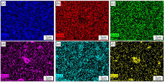
Figure 4.
Distribution of the elements in the Ag10CuZnSn-3In-0.5Ce filler metal: (a) Ag, (b) Cu, (c) Zn, (d) Sn, (e) In, and (f) Ce.
3.4. Shear Behaviors of the Joints Brazed with the Ag10CuZnSn-xIn-yCe Filler Metals
The Cu/Ag10CuZnSn-xIn-yCe/304 stainless steel brazed joints’ shear strength is shown in Table 3. It was found that fractures of all the joints occur inside the Cu plate side, indicating that the shear strength of the brazed joints is even higher than that of the Cu plate. Therefore, it can be predicted that Cu/304 stainless steel joints brazed using the Ag10CuZnSn-xIn-yCe filler metals have excellent mechanical properties.
Table 3.
Shear strength and fracture location of the Cu/304 stainless steel joints brazed with different Ag10CuZnSn-xIn-yCe filler metals.
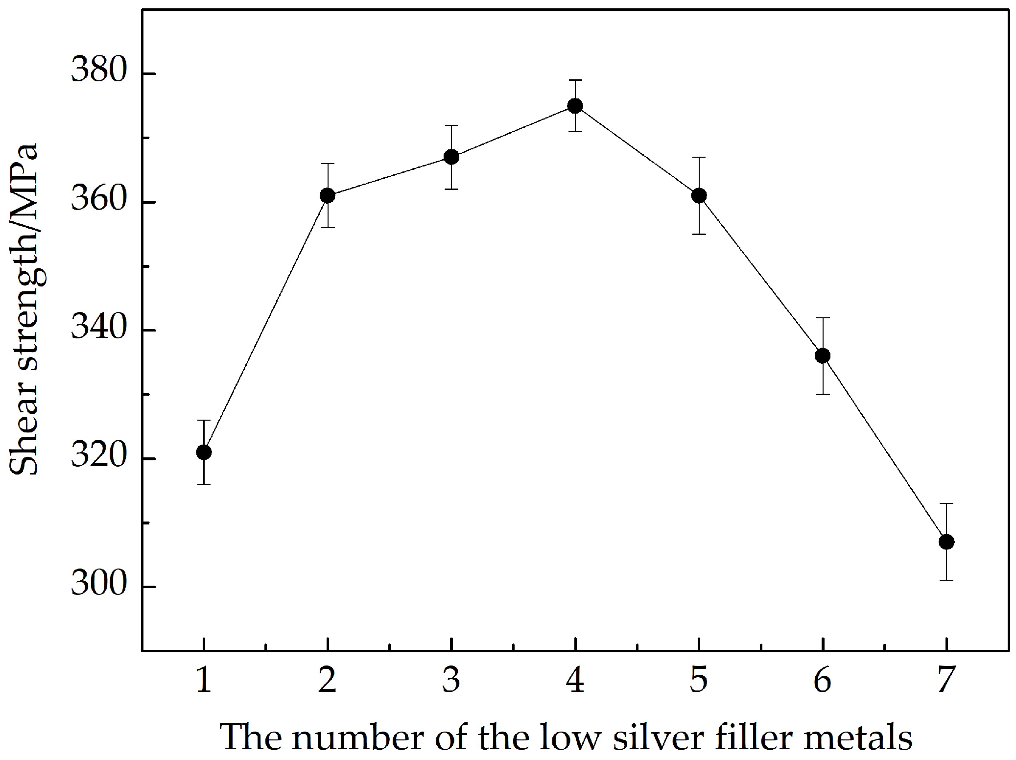
To further reveal the effects of the composite alloying of In and Ce on the mechanical properties of the Ag10CuZnSn brazed joints, the 304 stainless steel plates were lap brazed with the seven low-silver filler metals, and the shear strength of each group of brazed joints was tested. The results show that fractures of all the samples occurred in the brazing seams, and the shear strength is shown in Figure 5. The addition of In and Ce significantly improves the shear strength of the 304 stainless steel brazed joints. One reason is that the In can be dissolved into the Ag-rich and Cu-rich phases and thus strengthen the filler metal. Moreover, comparing the joints brazed with the No. 3 to No. 6 filler metals, it can be found that when the In content is constant, the shear strength increases with the increasing Ce content. When the contents of the In and Ce are 1.5 wt% and 0.15 wt%, respectively, the shear strength reaches a maximum value of 375 MPa, because the Ce can aggregate at the grain boundaries and refine the microstructure of the filler metal, and thereby improve the shear strength of the brazed joints. In general, the shear strength of the brazed joints is improved due to fine grain strengthening of the Ce element and solution strengthening of the In element. However, when the content of Ce is higher, the shear strength begins to decrease and is even lower than the joints brazed with Ag10CuZnSn.
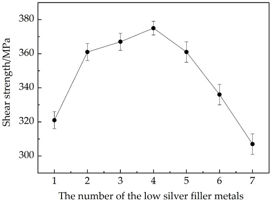
Figure 5.
Shear strength of the 304 stainless steel joints brazed with Ag10CuZnSn-xIn-yCe filler metals.
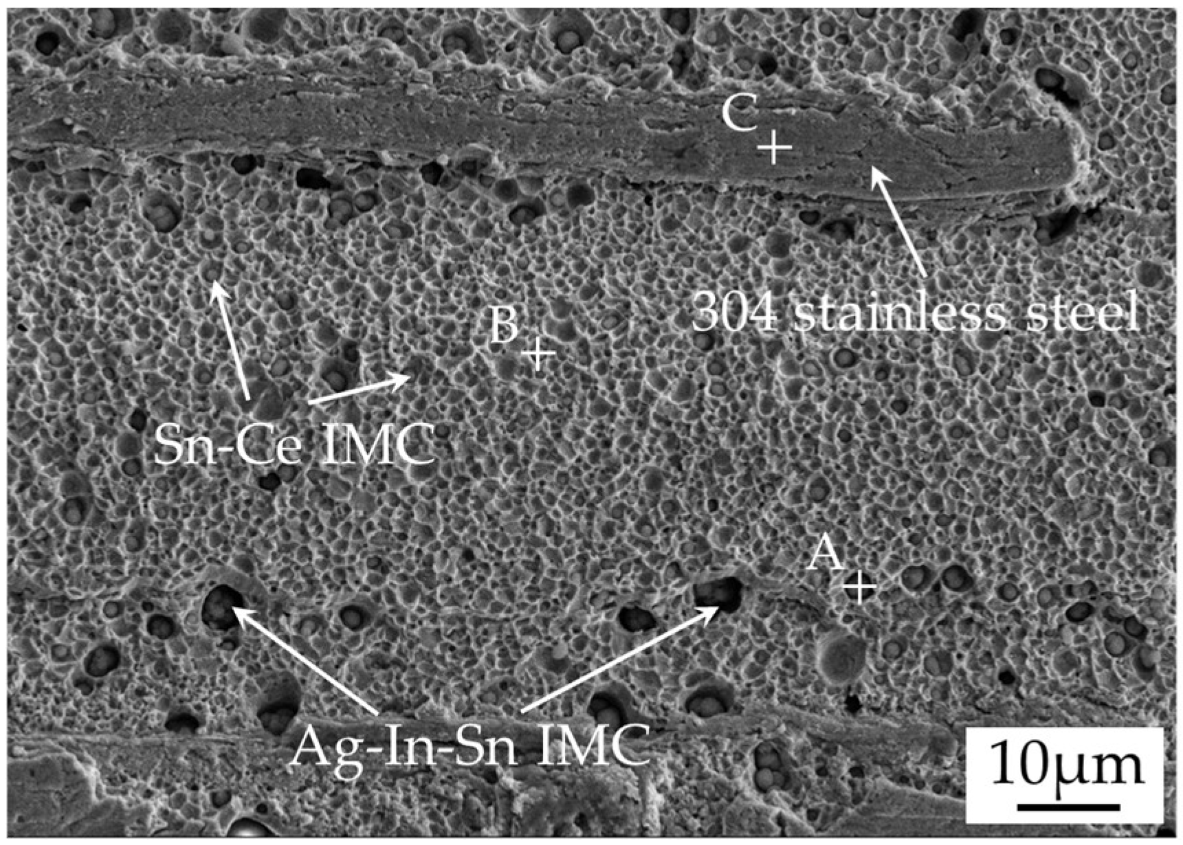
Figure 6 shows the microstructure and elements distribution in the 304 stainless steel/Ag10CuZnSn-3In-0.5Ce/304 stainless steel brazing seam, in which the Ag, In, and Sn elements overlap with the gray phase, and the Sn and Ce elements overlap with the bulk white phase. Thus, it is inferred that there are strips or blocks like In-rich IMC and bulk Sn-Ce IMC in seam. The corresponding fracture morphology of a brazed joint is shown in Figure 7, and combined with the EDS results shown in Table 4, it can be concluded that the A region was composed of the Cu4In and Ag9In4 IMCs and the B region was composed of the Ce2Sn3 IMC. As the IMCs are brittle, they can easily crack under stress, which decreases the shear strength of the joint [27]. According to the microstructure and shear strength, it is concluded that the optimal addition amounts of the In and Ce in the Ag10CuZnSn-xIn-yCe filler metal are 1.5 wt% and 0.15 wt%, respectively.
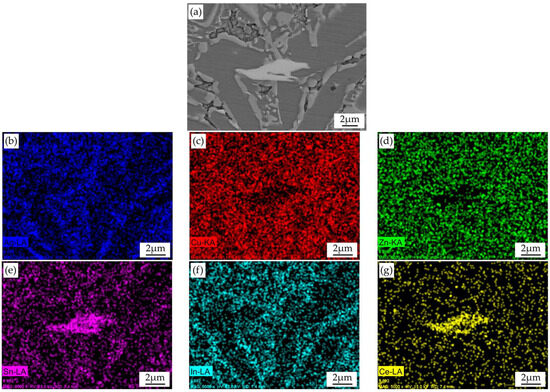
Figure 6.
Microstructure (a) and elements distribution in the seam of the 304 stainless steel/Ag10CuZnSn-3In-0.5Ce/304 stainless steel brazed joint: (b) Ag, (c) Cu, (d) Zn, (e) Sn, (f) In, (g) Ce.

Figure 7.
Fracture morphologies of the 304 stainless steel/Ag10CuZnSn-3In-0.5Ce/304 stainless steel brazed joint.
Table 4.
Chemical compositions of points A~C in Figure 7 characterized by EDS.
4. Conclusions
The combined effects of trace amounts of In and Ce elements on the melting behavior, spreading performance, microstructure, and mechanical properties of the Ag10CuZnSn filler metal were investigated in this study. Based on the experimental results and discussions, the main conclusions are as follows:
- (1)
- The addition of In can significantly decrease the solidus and liquidus temperatures of the Ag10CuZnSn filler metal, while trace amounts of Ce element have little influence on the melting temperature.
- (2)
- The composite addition of In and Ce can significantly improve the spreading performance of the Ag10CuZnSn filler metal. When the content of In is 1.5 wt% and Ce is 0.15 wt%, the spreading areas of the filler metal on Cu and 304 stainless steel plates increase by 21.1% and 35.7%, respectively.
- (3)
- The Ag10CuZnSn-xIn-yCe filler metals are composed mainly of Ag-based solid solution and Cu-based solid solution. The Ce element can refine the microstructure of the filler metal, and the refinement effect is the most obvious when the contents of In and Ce are 1.5 wt% and 0.15 wt%, respectively, while excessive In and Ce will form blocky IMCs in the filler metals.
- (4)
- Adding trace amounts of In and Ce into the Ag10CuZnSn filler metal can significantly improve the shear strength of the brazed joints, and the shear strength of the 304 stainless steel joints brazed with Ag10CuZnSn-1.5In-0.15Ce reaches a maximum value of 375 MPa. With higher contents of In and Ce, brittle Cu4In, Ag9In4 IMCs, and Ce2Sn3 phases appear in the brazing seam and the shear strength of the brazed joint decreases.
Author Contributions
Conceptualization, J.X. and Y.F.; methodology, J.X. and Y.Y.; software, J.X.; validation, J.X. and L.W.; formal analysis, J.X.; investigation, J.X.; resources, J.X., Y.F. and Z.L.; data curation, J.X. and J.W.; writing–original draft preparation, J.X.; writing—review and editing, J.X.; visualization, J.X.; supervision, Y.F. and S.X.; project administration, J.X., Y.F. and S.X.; funding acquisition, J.X. All authors have read and agreed to the published version of the manuscript.
Funding
This work was financially supported by the Start-up Fund for New Talented Researchers of Nanjing Vocational University of Industry Technology (Grant No. YK21-02-05).
Data Availability Statement
The data can be obtained from the corresponding author.
Conflicts of Interest
The authors declare no conflict of interest.
References
- Way, M.; Willingham, J.; Goodall, R. Brazing filler metals. Int. Mater. Rev. 2020, 65, 257–285. [Google Scholar] [CrossRef]
- Watanabe, T.; Yanagisawa, A.; Sasaki, T. Development of Ag based brazing filler metal with low melting point. Sci. Technol. Weld. Join. 2011, 16, 502–508. [Google Scholar] [CrossRef]
- Tajfar, M.; Ganjeh, E.; Mirbagheri, M. Evaluation of copper brazed joint failure by thermal-fatigue test applicable in heat exchangers. J. Alloy. Compd. 2016, 656, 347–356. [Google Scholar] [CrossRef]
- Esmati, K.; Omidvar, H.; Jelokhani, J.; Naderi, M. Study on the microstructure and mechanical properties of diffusion brazing joint of C17200 Copper Beryllium alloy. Mater. Des. 2014, 53, 766–773. [Google Scholar] [CrossRef]
- Baba, H.; Tsuneyama, K.; Yazaki, M.; Nagata, K.; Minamisaka, T.; Tsuda, T. The liver in itai-itai disease (chronic cadmium poisoning): Pathological features and metallothionein expression. Mod. Pathol. 2013, 26, 1228–1234. [Google Scholar] [PubMed]
- Taylor, M.; Mould, S.; Kristensen, L.; Rouillon, M. Environmental arsenic, cadmium and lead dust emissions from metal mine operations: Implications for environmental management, monitoring and human health. Environ. Res. 2014, 135, 296–303. [Google Scholar]
- Directive, E.U. Restriction of the use of certain hazardous substances in electrical and electronic equipment (RoHS). Off. J. Eur. Communities 2013, 46, 19–23. [Google Scholar]
- Wierzbicki, L.J.; Malec, W.; Stobrawa, J.; Cwolek, B.; Juszczyk, B. Studies into new, environmentally friendly Ag-Cu-Zn-Sn brazing alloys of low silver content. Arch. Metall. Mater. 2011, 56, 147–158. [Google Scholar] [CrossRef]
- Ahn, B. Recent advances in brazing fillers for joining of dissimilar materials. Metals 2021, 11, 1037. [Google Scholar] [CrossRef]
- Lai, Z.M.; Xue, S.B.; Lu, F.Y.; Gu, L.Y.; Gu, W.H. Effects of Ga and In on the properties of cadmium-free Ag-Cu-Zn filler metal. China Weld. 2009, 18, 33–38. [Google Scholar]
- Daniel, S.; Gunther, W.; Sebastian, S. Development of Ag-Cu-Zn-Sn Brazing Filler Metals with a 10weigh-% Reduction of Silver and Liquids Temperature. China Weld. 2014, 23, 25–31. [Google Scholar]
- Zhang, L. Filler metals, brazing processing and reliability for diamond tools brazing: A review. J. Manuf. Process. 2021, 66, 651–668. [Google Scholar]
- Roy, R.K.; Ghosh, M. Advancement of brazing filler alloy: An overview. Join. Process. Dissimilar Adv. Mater. 2022, 553–579. [Google Scholar] [CrossRef]
- Sisamouth, L.; Hamdi, M.; Ariga, T. Investigation of gap filling ability of Ag-Cu-In brazing filler metals. J. Alloys Compd. 2010, 504, 325–329. [Google Scholar] [CrossRef]
- Ma, C.L.; Xue, S.B.; Wang, B.; Wang, J.X.; Hu, A.M. Effect of Ce addition on the microstructure and properties of Ag17CuZnSn filler metal. J. Mater. Eng. Perform. 2017, 26, 3180–3190. [Google Scholar] [CrossRef]
- GB/T 11364-2008; Test Method of Wettability for Brazing Filler Metals. Standardization Administration: Beijing, China, 2008.
- GB/T 11363-2008; Test Method of the Strength for Brazed and Soldered Joint. Standardization Administration: Beijing, China, 2008.
- Cao, J.; Zhang, L.X.; Wang, H.Q.; Wu, L.Z.; Feng, J.C. Effect of Silver content on microstructure and properties of brass/steel induction brazing joint using Ag-Cu-Zn-Sn filler metal. J. Mater. Sci. Technol. 2011, 27, 377–381. [Google Scholar] [CrossRef]
- Ranjbar, K.; Dehmolaei, R.; Amra, M.; Keivanrad, I. Microstructure and properties of a dissimilar weld between alloy 617 and A387 steel using different filler metals. Weld. World 2018, 62, 1121–1136. [Google Scholar] [CrossRef]
- Ma, X.; Li, L.F.; Zhang, Z.H.; Hao, W.; Wang, E.Z.; Tai, Q. Microstructure and melting properties of Ag-Cu-In intermediate- temperature brazing alloys. Rare Met. 2015, 34, 324–328. [Google Scholar] [CrossRef]
- Tian, F.F.; Li, C.F.; Zhou, M.; Liu, Z.Q. The interfacial reaction between In-48Sn solder and polycrystalline Cu substrate during solid state aging. J. Alloys Compd. 2018, 740, 500–509. [Google Scholar] [CrossRef]
- Tian, F.F.; Liu, Z.Q.; Shang, P.J.; Guo, J.D. Phase identification on the intermetallic compound formed between eutectic SnIn solder and single crystalline Cu substrate. J. Alloys Compd. 2014, 591, 351–355. [Google Scholar] [CrossRef]
- Hodulova, E.; Palcut, M.; Lechovic, E.; Simekova, B.; Ulrich, K. Kinetics of intermetallic phase formation at the interface of Sn–Ag–Cu–X (X = Bi, In) solders with Cu substrate. J. Alloys Compd. 2011, 509, 7052–7059. [Google Scholar]
- Lejuste, C.; Hodaj, F.; Petit, L. Solid state interaction between a Sn-Ag-Cu-In solder alloy and Cu substrate. Intermetallics 2013, 36, 102–108. [Google Scholar]
- Wu, J.; Xue, S.B.; Yao, Z.; Long, W.M. Study on microstructure and properties of 12Ag-Cu-Zn-Sn cadmium-free filler metals with trace In addition. Crystals 2021, 11, 557–568. [Google Scholar] [CrossRef]
- Yin, X.H.; Ma, Q.S.; Cui, B.; Zhang, L.; Xue, X.Y.; Zhong, S.J.; Dong, X. Current review on the research status of cemented carbide brazing: Filler materials and mechanical properties. Met. Mater. Int. 2021, 27, 571–583. [Google Scholar]
- Winiowski, A.; Różański, M. Impact of tin and nickel on the brazing properties of silver filler metals and on the strength of brazed joints made of stainless steels. Arch. Metall. Mater. 2013, 58, 1007–1011. [Google Scholar] [CrossRef]

Disclaimer/Publisher’s Note: The statements, opinions and data contained in all publications are solely those of the individual author(s) and contributor(s) and not of MDPI and/or the editor(s). MDPI and/or the editor(s) disclaim responsibility for any injury to people or property resulting from any ideas, methods, instructions or products referred to in the content. |
© 2023 by the authors. Licensee MDPI, Basel, Switzerland. This article is an open access article distributed under the terms and conditions of the Creative Commons Attribution (CC BY) license (https://creativecommons.org/licenses/by/4.0/).