Article

Research on Single Crystal Preparation via Dynamic Liquid Phase Method

College of Materials Science and Engineering, Nanjing Tech University, Nanjing 211816, China
*
Author to whom correspondence should be addressed.
Crystals 2023, 13(7), 1150; https://doi.org/10.3390/cryst13071150
Submission received: 29 June 2023 / Revised: 17 July 2023 / Accepted: 21 July 2023 / Published: 24 July 2023

Abstract

:
Traditional liquid phase methods for growing single crystals are static growth methods, which include seed crystal sedimentation growth and seed crystal clamping growth using seed crystal holders. Single crystals grown via seed crystal sedimentation often have a flat and elongated shape, and the region in contact with the bottom of the container is restricted during growth, resulting in significant defects. Similarly, the seed crystal clamping growth method cannot avoid contact with external objects, leading to abnormal growth at the contact points and along the direction of the seed crystal holder, also resulting in certain defects. Both of these growth methods require processes, such as cutting and grinding, to remove defects, resulting in resource waste. To address the shortcomings of the static liquid phase single-crystal preparation mentioned above, this study successfully designed a dynamic liquid phase method for single crystal growth, which achieved the successful suspension of seed crystals in the mother solution and the growth of high-quality, large-sized single crystals, avoiding contact with the walls and the bottom of the container during the crystal growth process. Based on the dynamic liquid phase single crystal growth apparatus mentioned above, stable and dynamic liquid phase preparation was successfully achieved, ranging from seed crystals with a diameter of approximately 5 mm to single crystals with a diameter of approximately 20 mm, by controlling the cooling rate and adjusting the solution flow rate.

1. Introduction

The advancement of science and technology is closely related to the semiconductor industry, and the energy shortage makes the photovoltaic field the leader. However, all of these are inseparable from single-crystal materials. Very few single-crystal materials in nature cannot guarantee their application in society, so preparing single-crystal materials [1,2,3] is particularly important.
There are many methods for growing crystals, generally divided into melt [4], solution [5], and vapor [6] growth. In solution growth, there are two methods, the sol–gel method [7] and the hydrothermal method [8], with the hydrothermal method being the focus of this paper. When Shaoli Wang et al. [9] studied the growth of metal halide perovskite materials, they used bottom-seeded solution growth and top-seeded solution growth in solution growth to cultivate metal halide perovskite single-crystal materials; Mingming Chen [10] and his team also synthesized high-quality all-inorganic CsPbBr3 single crystals using the solution growth method. However, when they used the solution growth method, using a seed crystal rod was unavoidable. This caused certain defects in the single-crystal material when it was fixed by the seed crystal rod, which had to be eliminated by cutting or polishing in later stages, resulting in a waste of resources. Therefore, this article introduces an improvement based on the solution growth method, which allows the crystal to grow freely suspended in the solution without being fixed by a seed crystal rod.
This article successfully cultivated copper sulfate single crystals using the modified solution growth method. The crystals grew uniformly on all sides, and the growth rate could be controlled by adjusting the flow rate, significantly reducing the time and cost of crystal growth.

2. Materials and Methods

2.1. Raw Materials

2.1.1. Copper Sulfate Powder

Shanghai Xinbao Fine Chemical Factory produced the raw material. Its chemical formula is CuSO4, with a molecular weight of 159.6. The impurity content is shown in Table 1, and the phase analysis is shown in Figure 1, which closely matches the PDF#01-0103 card.

2.1.2. Water

The ultrapure water used in this article was self-made using laboratory equipment from ShuHuoQuan Company. It was produced strictly according to the national standard GB/T6682-2008 for laboratory water analysis.

2.2. Experimental Methods

2.2.1. Preparation of Seed Crystals and Determination of Solubility

Preparing seed crystals involves the spontaneous crystallization of copper sulfate solution into small particles as the temperature decreases and the solvent evaporates. To ensure the saturation of the copper sulfate solution, it is essential to understand its solubility [11] accurately. However, as too many interfering factors affect solubility, this article also conducted relevant experiments to measure the solubility of copper sulfate and prepare the required seed crystals before starting the investigation.
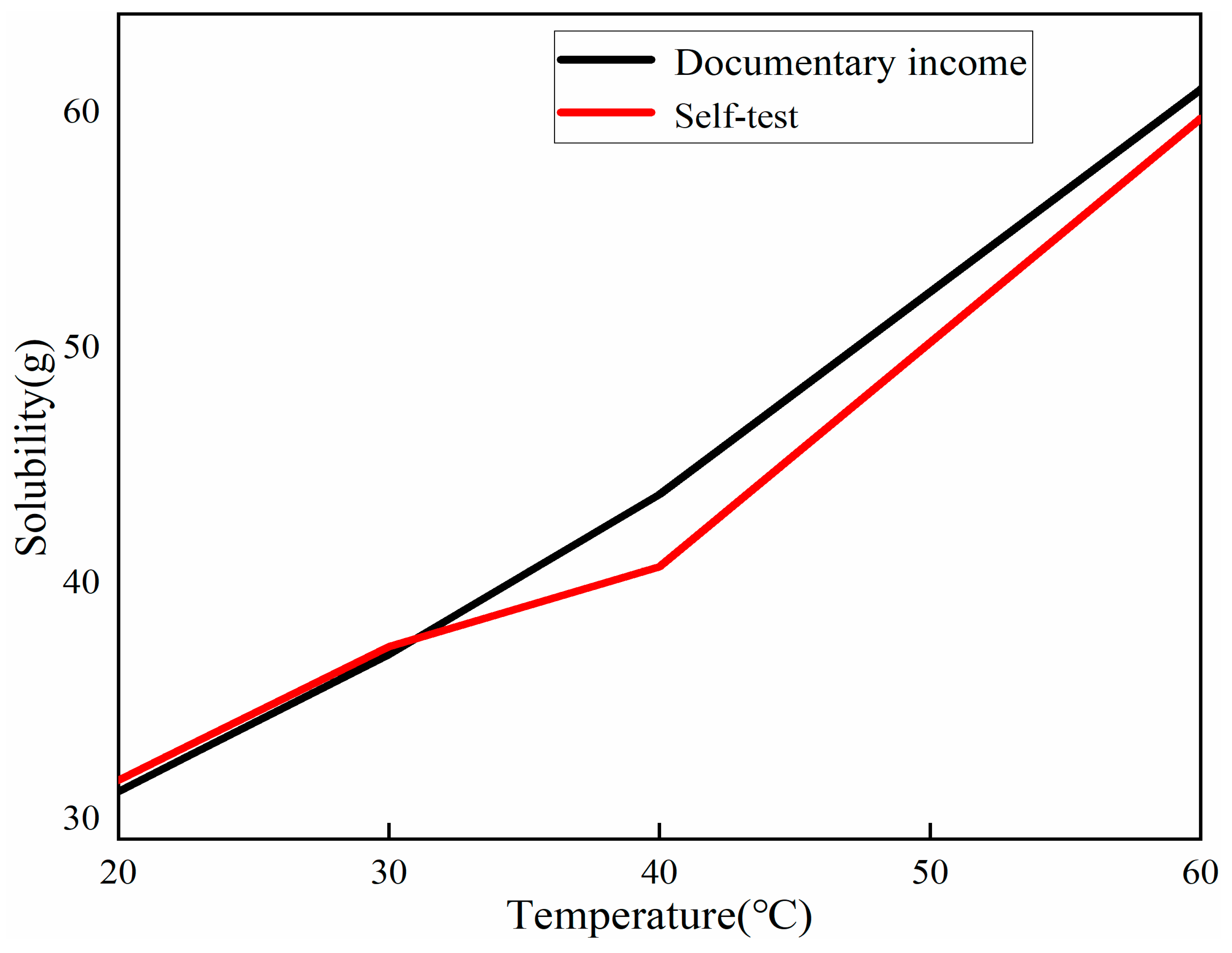
After pouring 40 mL of distilled water into a 100 mL beaker, excess copper sulfate powder was added to the beaker based on the copper sulfate solubility obtained from the literature [11]. The solution was then heated to 10 °C, 20 °C, 30 °C, 40 °C, and 60 °C and stirred until full dissolution was achieved. The heating and stirring process continued until excess copper sulfate powder could no longer be dissolved. The solution was then filtered using a Brinell funnel, and the filtrate was poured into the beaker. The beaker was then placed in a blast dryer to evaporate the solvent. The resulting solute was weighed separately to determine its mass and, thus, calculate the exact value of local copper sulfate solubility. The amount of solute at different temperatures (including the weight of the bottle) is shown in Figure 2; the data were organized as shown in Table 2, and the solubility of copper sulfate is shown in Figure 3.

2.2.2. Traditional Solution Method

To begin, prepare a 50 mL saturated copper sulfate solution at 30 °C. Pour the solution into a beaker and place the beaker inside a temperature-controlled chamber set at 30.1 °C. This ensures the prepared saturated copper sulfate solution does not crystallize due to contact with the cooler beaker walls. Prepare copper sulfate seed crystals with a size of approximately 5 mm in advance. Place the seed crystals on a glass slide and transfer them to a blast drying oven set at 30 °C. This allows the seed crystals to acclimate to the desired temperature, preventing premature crystal precipitation due to the lower surface temperature of the seed crystals when placed into the saturated copper sulfate solution. Additionally, this step enables the partial dissolution of any defective portions on the surface of the seed crystals when they come into contact with the higher temperature of the saturated copper sulfate solution, thereby ensuring better crystallinity. Subsequently, introduce the seed crystals into the supersaturated copper sulfate solution using different methods. Designate samples with seed crystals clamped using seed crystal holders as CY. For samples grown using seed crystal sedimentation, designate them as CN. Place the examples in the temperature-controlled chamber to facilitate crystal growth.
Crystal growth conditions: temperature cooled from 30 °C to 14 °C; the cooling rate was 2 °C/d.

2.2.3. Dynamic Liquid Solution Growth Method

Place the pre-prepared seed of approximately 3 mm onto the seed crystal tray of the crystal growth apparatus. Then, seal the apparatus and immerse it in a temperature-controlled water bath set at 30.1 °C. Allow the apparatus to equilibrate for approximately 5 h, ensuring that the internal temperature matches the temperature of the water bath. This step prevents immediate crystal precipitation upon contact with the solution. Next, pour the saturated copper sulfate solution at 30 °C into the apparatus through the inlet. Open all valves during pouring and ensure a slow and steady flow to ensure complete apparatus filling. Once everything is in place, use the gas nozzle to seal the inlet and exhaust vent. Set the program of the intelligent segmented temperature controller according to Table 3 and initiate the crystal growth process (samples prepared using the crystal growth apparatus are designated as CI).
Crystal growth conditions: temperature cooled from 30 °C to 28.8 °C; the cooling rate was 0.05 °C/h.

3. Results and Discussion

3.1. Crystal Structure

3.1.1. Crystal Shape

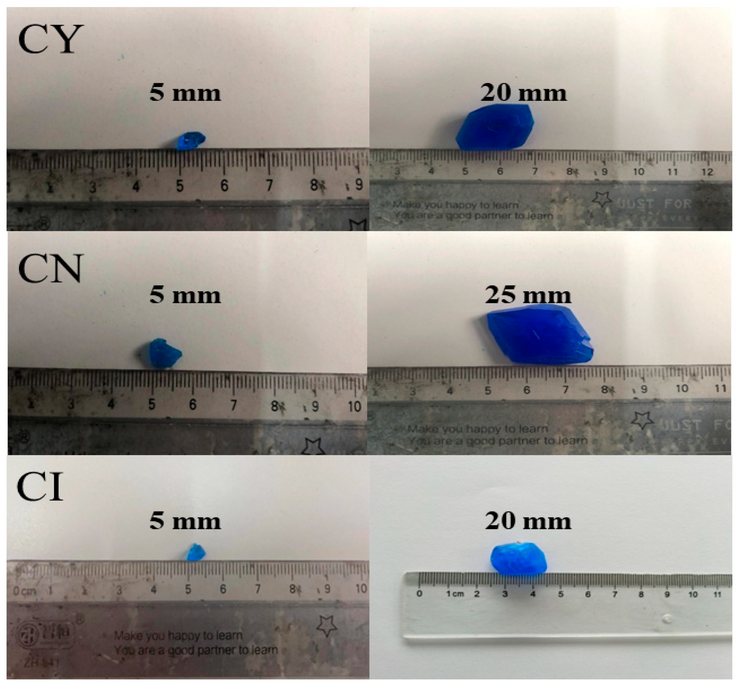
The crystals grown using the static and dynamic solution method are shown in Figure 4.
By comparing their sizes, it can be observed that sample CN grown using the traditional solution method is longer than sample CY. However, CN is thinner and has more surface defects. This is because CN grows in close contact with the bottom of the container, limiting its growth freedom in the vertical direction. Additionally, the temperature gradient is lowest at the bottom of the container, which promotes preferential growth in that region. On the other hand, samples CY and CI show no difference in their external appearance and size.

3.1.2. XRD Polycrystalline Powder Diffraction

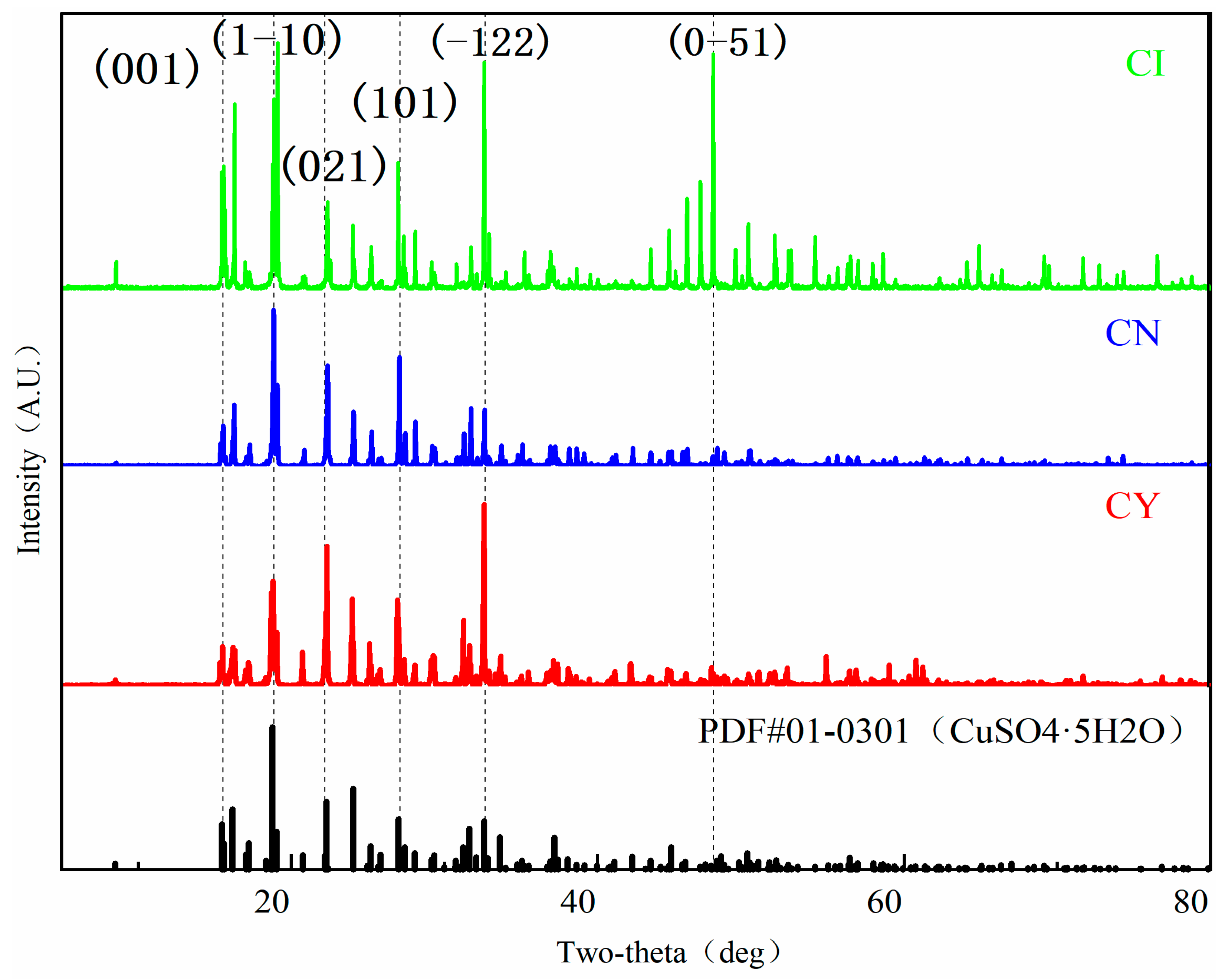
The obtained samples CY, CN, and CI from the experiment were dried and powdered. The resulting powders were sieved using an 80 μm sieve and characterized using a 3 kW XRD (X-ray diffraction) device from Rigaku, Japan. The scanning range of 2θ was set from 5° to 80° with a step size of 0.01° and a scanning speed of 10°/min. The obtained XRD patterns are shown in Figure 5.
By comparing the X-ray diffraction (XRD) patterns of the polycrystalline powders [12] of CN, CY, and CI with the PDF card 01-0301, it can be concluded that the grown crystals are of pure copper sulfate phase.

3.1.3. XRD Single-Crystal Diffraction

The experimental samples CY, CN, and CI were characterized using a bulk XRD device, the Rigaku 3 kW XRD, from Japan. The scanning range of 2θ was set from 5° to 80° with a step size of 0.01° and a scanning speed of 10°/min. The obtained XRD patterns are shown in Figure 6.
The XRD patterns obtained from the bulk samples of CN, CY, and CI, when compared with the PDF card 01-0301, confirm that all the bulk samples exhibit diffraction peaks corresponding to copper sulfate crystals. However, the positions and completeness of the diffraction peaks vary among the samples, indicating a strong orientation of the crystal lattice in the measured samples, a characteristic feature of single-crystal diffraction. The CN sample shows no significant peak shifts but has a relatively large peak broadening, indicating a lower degree of crystallinity. The CY sample exhibits a shift in the (002) peak and good peak sharpness, suggesting an enlarged unit cell and a higher degree of crystallinity. Similarly, the CI sample shows a shift in the (−2−12) peak with excellent peak sharpness, indicating an enlarged unit cell and even higher crystallinity.
Comparing CN and CY, it can be observed that sample CY grown using the traditional solution method with seed crystal clamping exhibits superior crystallinity and size. This indicates no restrictions on growth freedom during the crystal growth process, allowing for the growth of high-quality single crystals. Comparing CY and CI, their morphologies are generally consistent. However, CY shows evident defects at the clamping point of the seed crystal. Therefore, in the absence of seed crystal clamping and without restrictions on growth freedom, the crystallinity of the crystal will be higher.

3.2. Design of Improved Solution Growth Method Apparatus

3.2.1. Design Principle

Typically, in the static liquid phase solution method for crystal growth, the crystal needs to be fixed in the appropriate position using a seed crystal clamping rod. However, the contact between the clamping rod and the seed crystal can affect the crystal’s growth, leading to inhibited growth or the formation of defects. Although defects near the clamping rod can be removed through subsequent processes, such as cutting and polishing, this wastes resources and reduces the efficiency of the single-crystal preparation. To address this issue, this study proposes a dynamic liquid phase single-crystal growth method that eliminates the need for a seed crystal clamping rod. This method utilizes the drag force acting on solid particles in the liquid, allowing them to be suspended and avoiding direct contact between the seed crystal and a solid object, similar to a clamping rod. Based on these principles, a liquid phase single-crystal growth apparatus without a clamping rod, called the suspended dynamic liquid phase single-crystal growth apparatus, is utilized. Creating the flow field within the apparatus, a contact-free growth environment for the seed crystal and its subsequent growth process is achieved. A schematic diagram is shown in Figure 7.
When the fluid moves upwards, and solid particles are present, the fluid will exert a corresponding drag force on the solid particles. When the drag force [13,14] and buoyancy force acting on the particles are equal to the weight of the particles, the solid particles will reach an equilibrium state and suspend in the liquid, as shown in Equations (1) and (2).
G F b u o y a n c y = F D
F D = 1 2 A p ξ p v 2
In the equation, FD represents the drag force, CD is the drag coefficient, ρf denotes the fluid density, Af means the cross-sectional area of the object’s perimeter, and υ refers to the terminal velocity of the fluid. Terminal velocity, or critical velocity, is the maximum velocity at which a fluid passes through. This concept is significant in the design and analysis of fluid and gas flow in pipes or other environments, as it indicates that once the fluid velocity reaches this value, it will not increase further. When determining the growth space for crystals, the value of Af can also be easily obtained.
When the aforementioned particles refer to seed crystals, the seed crystal will remain suspended when the surrounding liquid is a saturated solution of the same substance as the seed crystal. In this case, the seed crystal will be in a dynamic equilibrium state, neither growing nor dissolving. However, when the solution is supersaturated, meaning it contains a higher concentration of solute than its saturation point, the excess solute in the solution will crystallize on the surface of the seed crystal. As a result, the seed crystal can gradually grow, while the solute in the solution will be gradually consumed, reaching a new dynamic equilibrium. By gradually reducing the solution’s temperature, the solute’s solubility decreases, leading to continuous crystallization on the seed crystal’s surface and facilitating the crystal’s continued growth. This principle allows for the growth of crystals without contact between the seed crystal and a solid object, such as a seed crystal rod or container wall, as demonstrated in this study.
The solute crystallization rate on the seed crystal’s surface is influenced by the total amount of the solution and the rate at which the solution is cooled. An excessive crystallization rate can lead to the formation of lattice defects, such as dislocations on the crystal surface, making it difficult to achieve the preparation of single crystals. Therefore, strictly controlling the cooling rate is necessary to ensure slow solute growth on the seed crystal surface, preventing defects such as dislocations.

3.2.2. Design Solutions

The present study will utilize acrylic material to fabricate the crystal growth apparatus. Acrylic is a common type of plastic material known as polymethyl methacrylate (PMMA). Its advantages make it a popular material used in various fields. The choice of this material for constructing the device is primarily due to its low cost and high transparency, allowing for clear observation of the internal device’s internal state.
With a final single-crystal size of 20 mm, according to Equation (3), the drag force that can suspend the copper sulfate crystal in water is approximately 0.8N.
According to Equation (1), the crystal’s terminal velocity [15] when suspended is approximately 1.61 m/s. According to Equation (3), the flow [16] rate required to suspend the crystal is approximately 1.64 L/s.
Q = SV
Considering the irregular [17,18] shape of the seed crystal and its tendency to move outward due to the drag force, to prevent the seed crystal from contacting the walls of the growth vessel and minimize the occurrence of defects, this study designed a concentric dual-channel annular fluid inlet structure. This structure consists of two trumpet-shaped openings, as shown in Figure 8. The application of this design in the liquid phase dynamic single-crystal growth provides an effective means to achieve high-quality single crystals and reduce adverse factors during the crystal growth process. Through the rational design of the trumpet-shaped openings, the seed crystal can be effectively protected, and the quality and integrity of crystal growth can be enhanced.
The internal dimensions consist of a platform with a bottom diameter of 16 mm, a slope of 65°, and a height of 30 mm. This design incorporates a platform with spray nozzles on both sides, providing the necessary drag force for crystal growth. This configuration ensures that the crystal remains suspended without touching the vessel walls. To facilitate the initial placement of the seed crystal in the device, a mesh structure is installed at the crystal placement location marked as point E. The three views of this structure are shown in Figure 9.
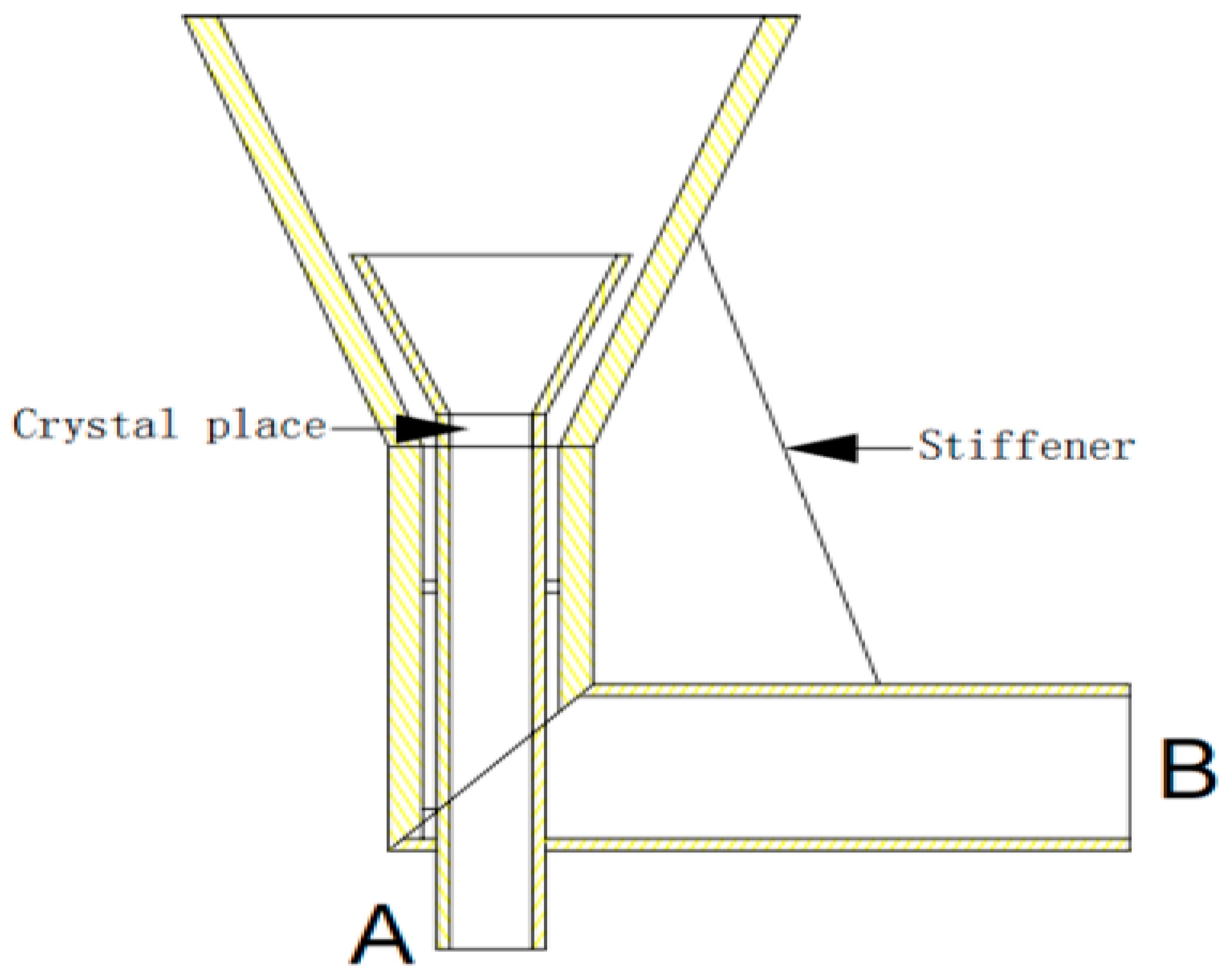
To ensure the verticality of the water column, it is necessary to place the water pump directly below the nozzle so that the water column can be sprayed vertically. The nozzle piping connection diagram is shown in Figure 10.
In the diagram, Port A is the vertical inlet for the nozzle, and it is also secured within the pipe using two small squares to prevent easy lateral movement. Its dimensions are 16 mm, with a wall thickness of 2 mm. Port B is the inlet for the circular nozzle area, with dimensions of 28 mm and a wall thickness of 2 mm. The entire structure is reinforced for stability. During actual operation, due to the significantly larger area of Port A compared to the circular nozzle area, the flow velocity at Port A is smaller, while the flow velocity at the circular nozzle area is larger.
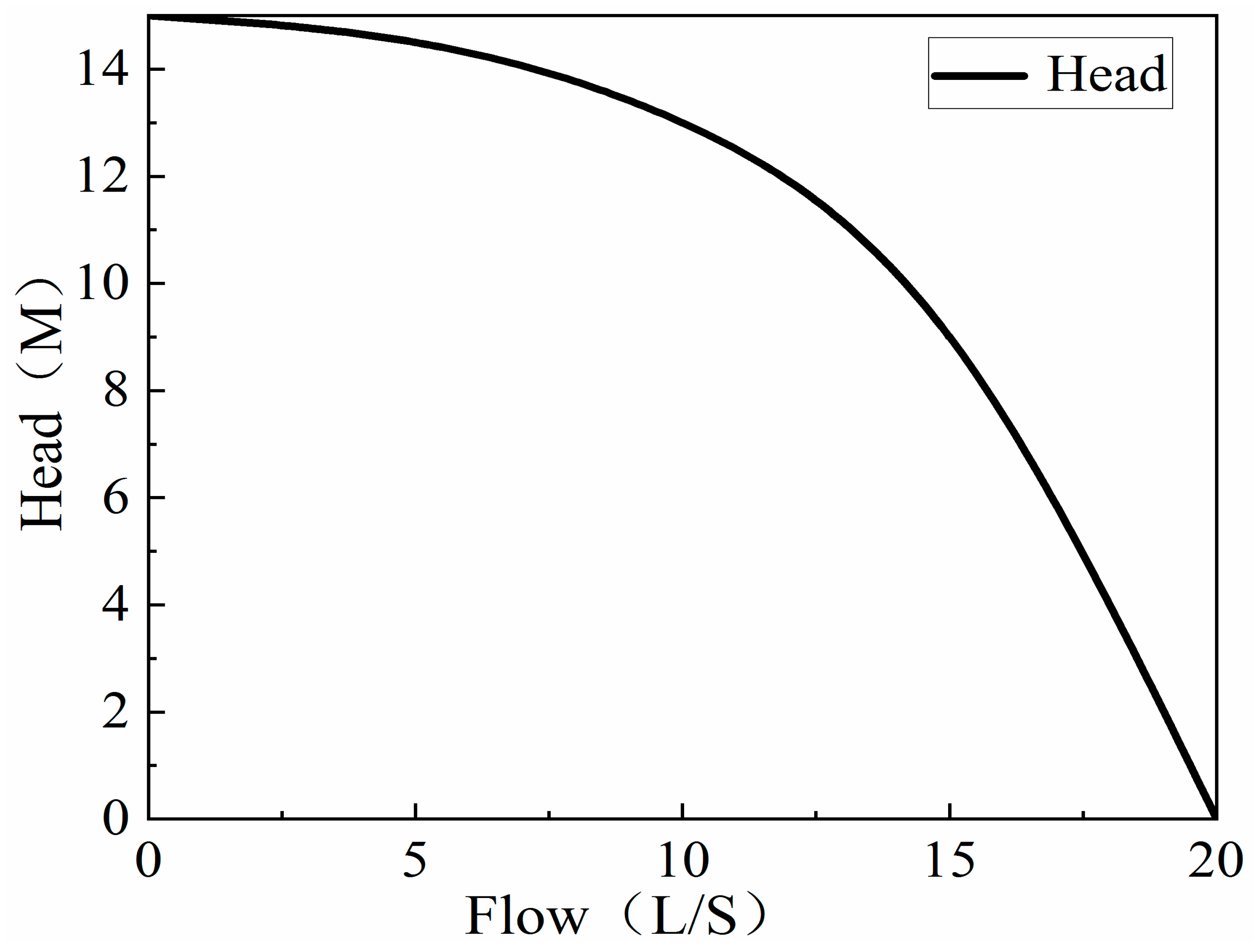
In order to ensure that the pressure inside the pipes [19,20,21] does not become excessively high, the flow velocity in the circular pipe should not exceed 5 m/s [22], and the flow velocity in the remaining main pipes should not exceed 20 m/s. Given that the pipe radius is approximately 11.445 mm, the calculated flow rate at the circular nozzle area is approximately 6.38 L/s. Therefore, an appropriate submersible pump can be chosen as the power source for the device. The pump’s head–capacity curve [23] is shown in Figure 11.
To facilitate the handling of the seed crystal and grown crystal, a flange connection is used to secure the apparatus. The main body of the crystal growth apparatus can be divided into two parts: the upper and lower parts. Flange plates are used to secure the bottom of the upper part and the top of the lower part, with flange gaskets placed between them. By using bolts to tightly connect the two flange plates, airtightness is ensured, as shown in Figure 12.
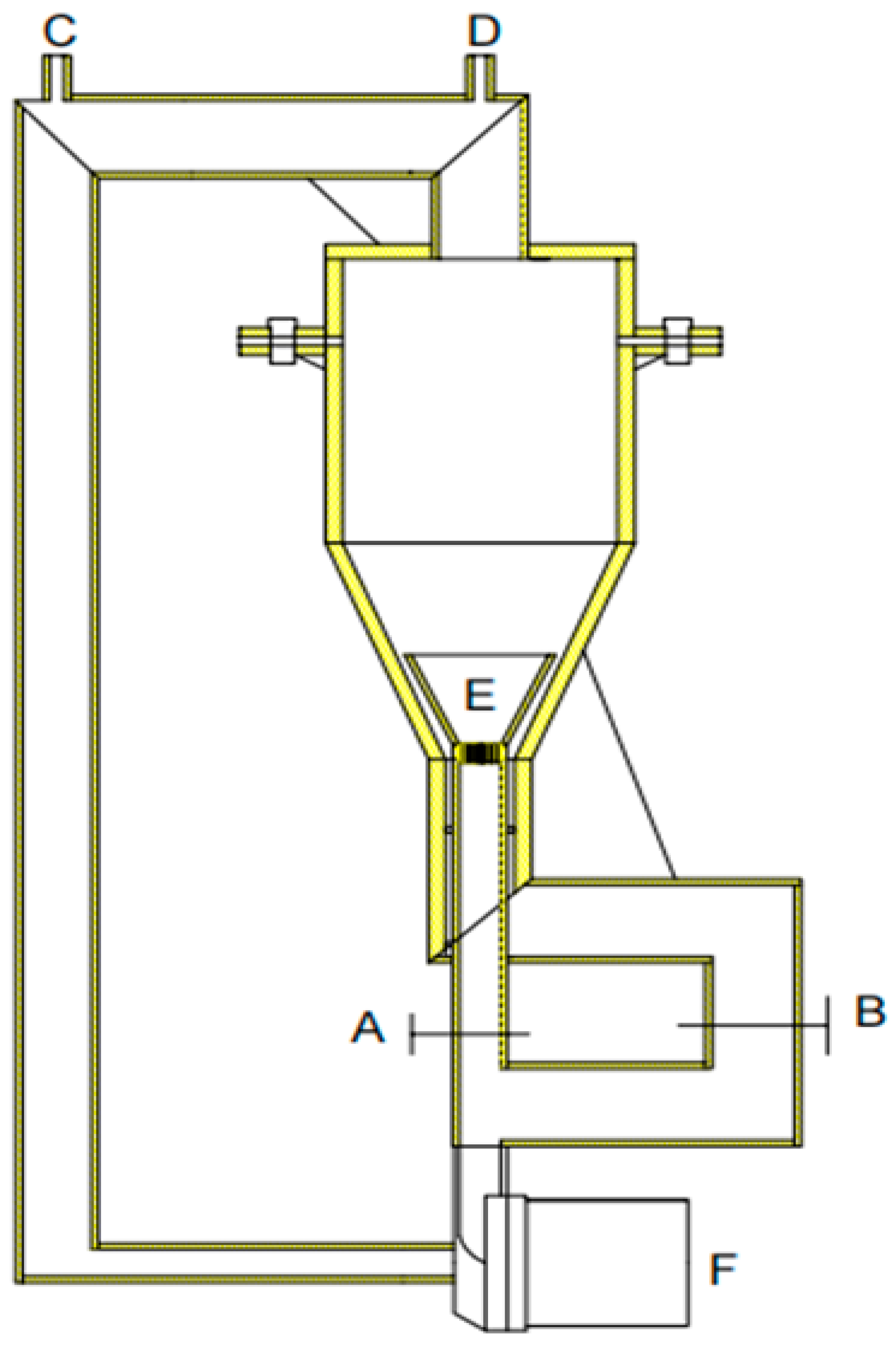
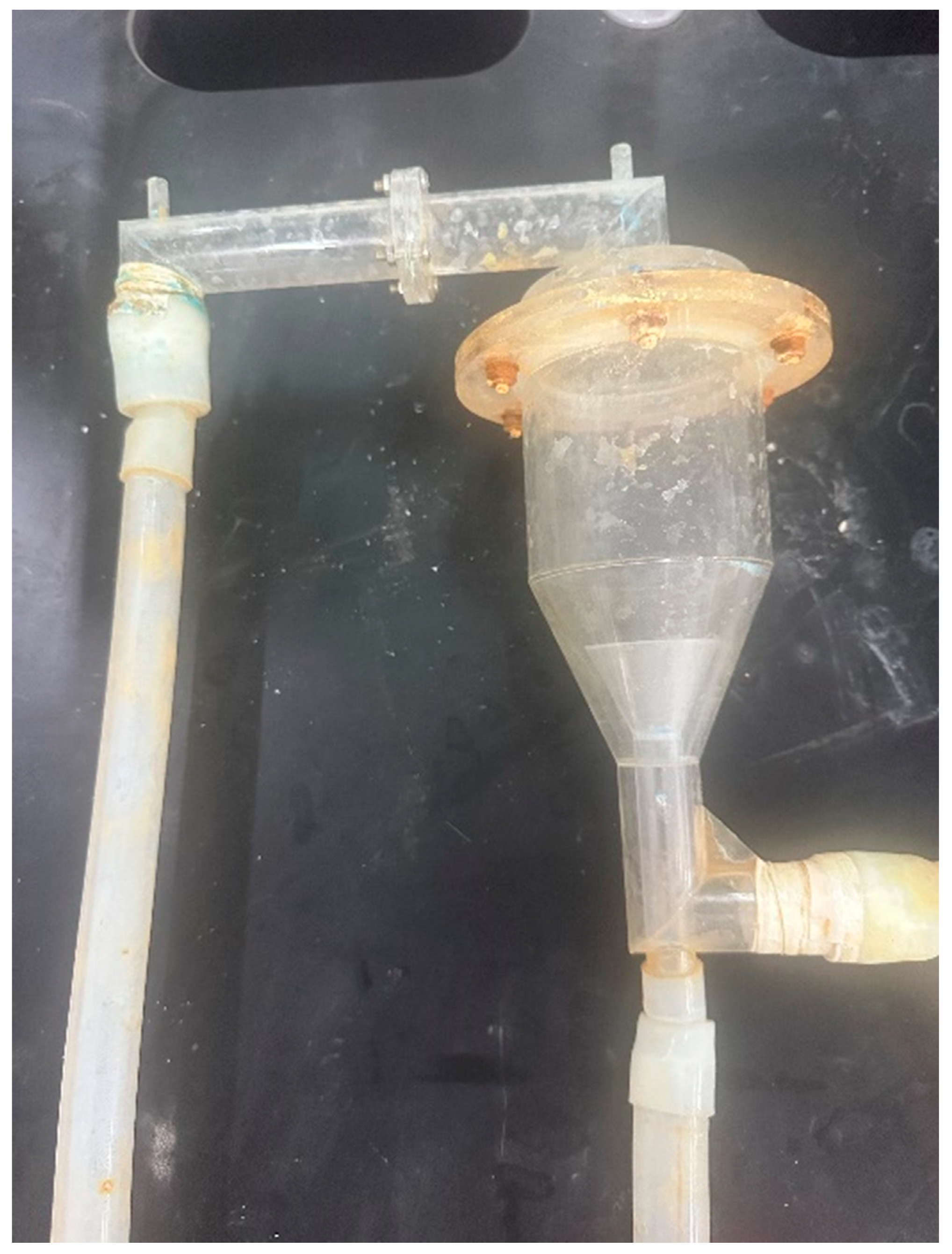
The principle of this experiment is based on the decrease in solubility of the solution with decreasing temperature, which promotes the continuous precipitation of the solute and facilitates crystal growth. This principle allows for the continuous growth of crystals without the need for adding additional materials during the process, ensuring the stability of the experimental environment and producing pure crystals without impurities. To implement this principle, a circulation system needs to be prepared to allow the solution to circulate within the system. A pipe is introduced above the crystal growth space, directly connected to the inlet of the submersible pump. Then, the A and B ports from Figure 10 are connected, and they are also connected to the outlet of the submersible pump, forming the structure of the entire crystal growth apparatus, as shown in Figure 13. The mathematical model of the device is shown in Figure 14.
In the diagram, F represents a suitable submersible pump with an appropriate head, and its outlet is connected to the vertical nozzle and the annular nozzle for crystal growth. E indicates the crystal placement area. C and D represent the inlet and outlet for the entire device, respectively, so that when the solution is irrigated through C, gas is discharged from D. A and B are valved for the vertical and annular nozzles. Since the initial seed crystal is small and does not require a large flow rate to keep it suspended, we can control the tightness of valves A and B based on the growth rate of the seed crystal to control the flow rate in the pipeline. Otherwise, the seed crystal can be easily blown into the submersible pump by a large flow rate, causing irreversible loss and experimental failure. Flow rate control by valves also ensures that the seed crystal can always remain within a certain range during the growth process. A physical diagram of the device is shown in Figure 15.
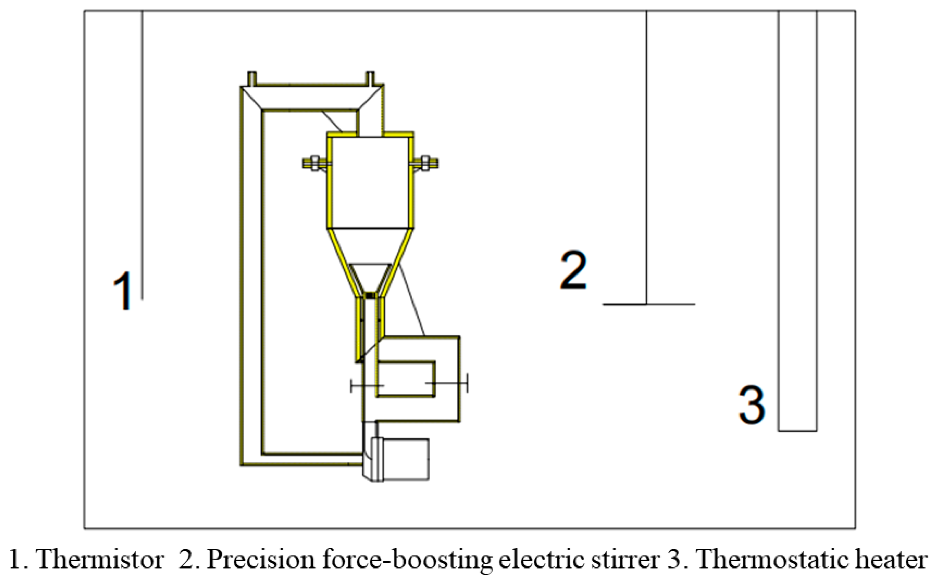
Place the entire apparatus in a temperature-controlled chamber to achieve crystal growth by controlling temperature variations, as shown in Figure 16.
In the figure, 1 is an NTC 10 k thermistor used for measuring water temperature with an accuracy of up to 0.1 °C; 2 is a JJ-1 precision force-boosting electric stirrer used to maintain the uniformity of water temperature in the closed space; and 3 is a 2 kW thermostatic heater with an external intelligent segmented heating thermostat used to keep the temperature of water in the closed space.
The specific operation of the device is as follows: First, use the thermostatic water temperature heater to heat the tank to a fixed temperature, T. Then, place the target seed crystals into the grid disc spout and use the flange connection to seal the entire device. It should be placed in the tank for more than two hours to ensure that the temperature inside the device and the surface of the seed crystals reaches T. This can prevent the occurrence of early growth or dissolution caused by temperature differences between the surface of the seed crystals and the solution during solution dumping. Then, pour the saturated solution at temperature T from port C. Port D should be open to discharge the gas inside the device. Notably, the pump should be stopped when the solution is poured to prevent gas binding. When the device is fully filled with the solution, ports C and D and valve A are closed, followed by starting the operation of the submersible pump. Although the device runs during this time, the seed crystal is not subjected to traction. Then, valve A is slowly opened, and the movement of the seed crystals in the solution is observed. After ensuring that the seed crystals are blown to a certain height, valve A is no longer opened. At that time, the seed crystals are provided traction by the grid disc spout and ring spout, only on the side of the device to conduct irregular movements without touching the wall. Furthermore, valve A should be gradually opened as the seed crystal grows so that the grid disc spout can provide greater traction. Finally, a temperature controller controls the temperature in the tank for the saturated solution at temperature T to drop below its solubility, which will cause the precipitation of crystals.

3.3. Comparative Analysis of Single Crystals Prepared using Liquid Phase Method

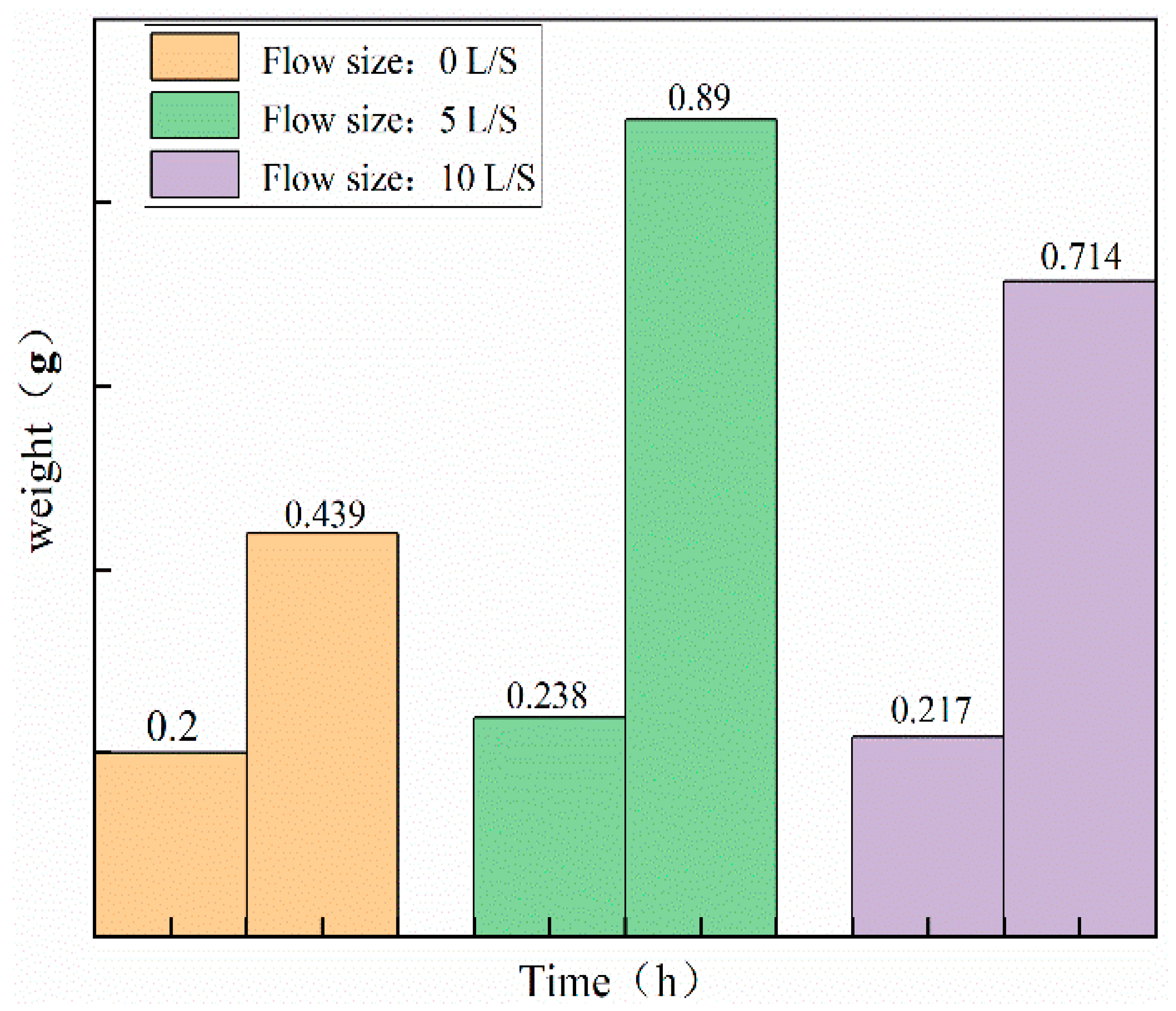
The difference between static solution growth and dynamic solution growth lies in the mode of mass transfer. In static growth, the solution is in a stagnant state, and diffusion is the main mode of mass transfer. In dynamic growth, the solution is in motion, and the flow rate is controllable, with convective mass transfer being the main mode. The different modes of mass transfer can also affect the growth rate of crystals. To compare the crystal growth using the static growth method with a crystal rod for 8 h and the dynamic growth method with varying flow rates for 8 h, the variation in crystal quality is shown in Figure 17.
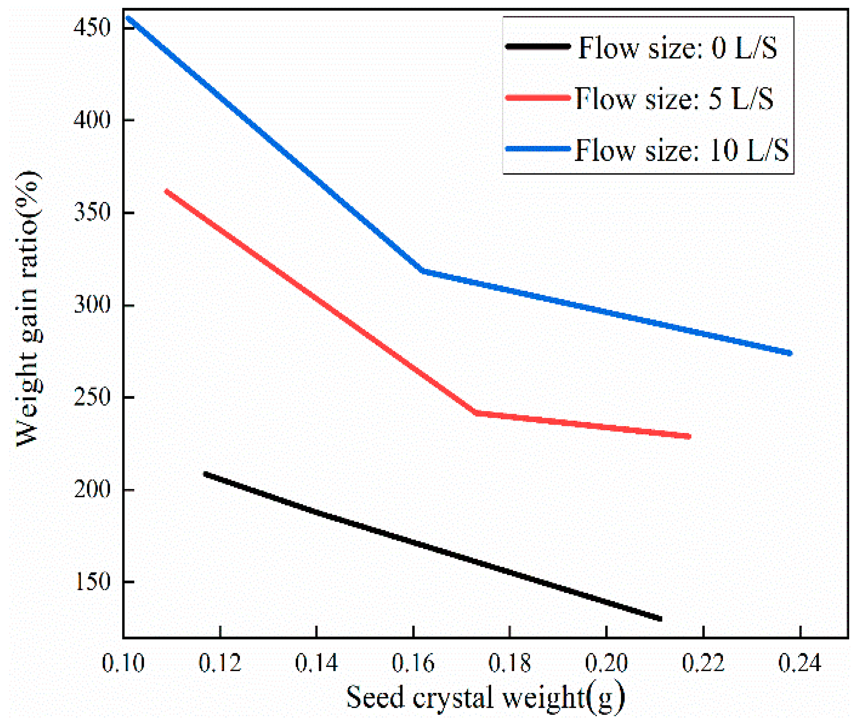
The experiment shows that the quality of crystals produced by the static growth method increases at a slower rate, while the quality of single crystals produced by the dynamic growth method with a flow rate of 5 L/s increases at a faster rate. The growth rate ratio of the quality increase is shown in Figure 18.
The experiment shows that the mass/increase ratio of crystals grown via the traditional solution method is significantly lower compared to the mass/increase ratio of crystals grown using the improved method. Additionally, the smaller the seed crystal, the higher the mass increase ratio, and the higher the flow rate, the higher the mass increase ratio.
In the static liquid phase solution method for single crystal growth, the concentration of the solution around the seed crystal decreases as the crystal grows. In this case, regions with higher concentrations in the solution move towards the vicinity of the seed crystal through diffusion mass transfer to maintain the uniformity of the solution concentration. On the other hand, in the dynamic liquid phase solution method, the uniformity of the solution concentration is maintained through convective mass transfer. Convective mass transfer is much faster than diffusion, resulting in a significantly higher growth rate of single crystals in the dynamic liquid phase solution method compared to the static liquid phase solution method.

3.4. Discussion

3.4.1. Air Binding and Pouring Pump

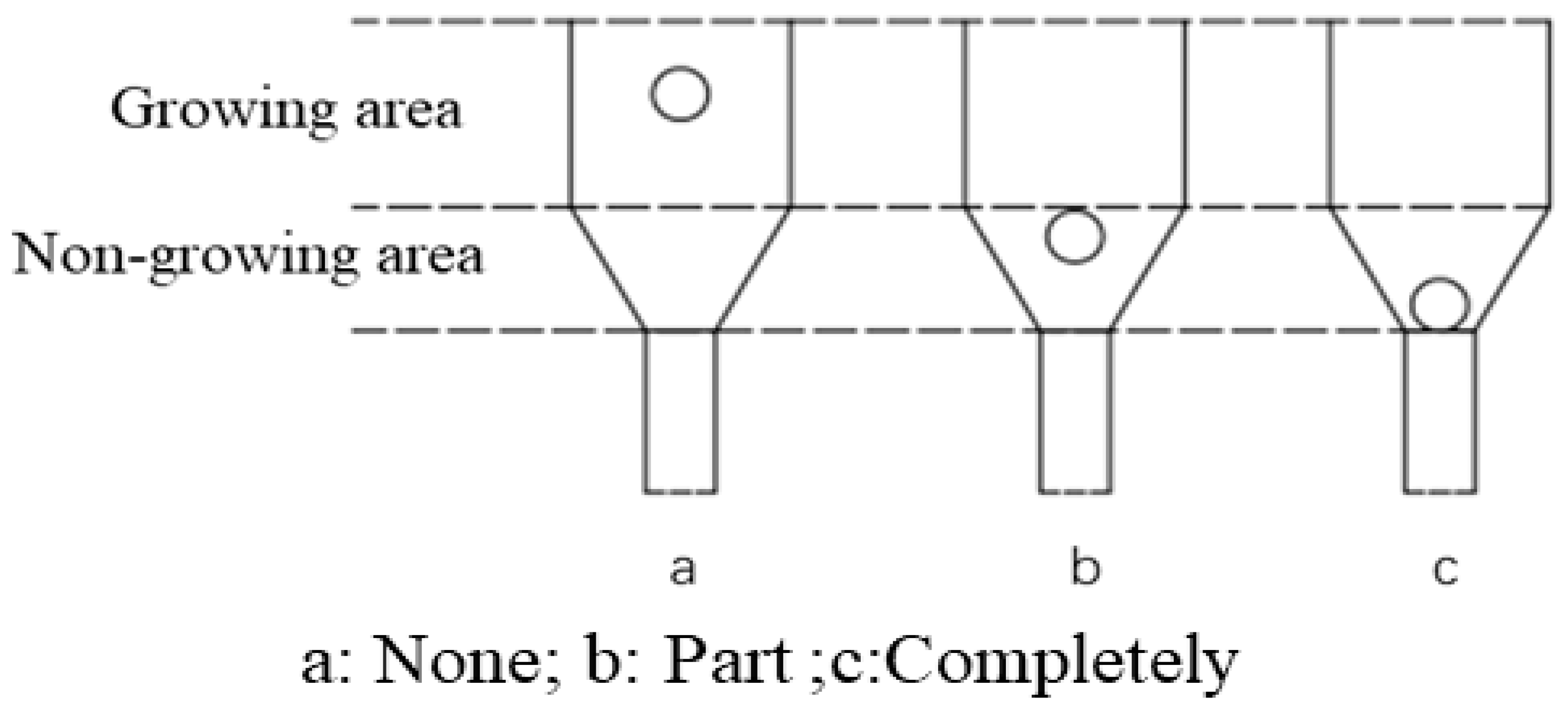
Before the submersible pump [24] starts operating, it must be filled with liquid along with the surrounding pipes. Once it starts running, the blades [25,26] rotate at high speed, causing the liquid inside to diffuse outward and increase in pressure due to centrifugal force. As a result of the high-speed rotation of the impeller, a certain vacuum is created at the center of the impeller, causing the external liquid to be drawn into the submersible pump under atmospheric pressure, initiating the circulation process. However, if the pump and its surrounding pipes are not filled with liquid, or if air enters the system under the influence of centrifugal force, the lower-density air will be preferentially drawn into the center of the impeller, while the liquid will be trapped on the outside. With the presence of air in the impeller center, the centrifugal force acting on the liquid will be reduced, resulting in the submersible pump being unable to operate properly. When there is gas in the pump, the crystal growth area experiences difficulties in achieving smooth crystal growth, as shown in Figure 19.
Figure 19a shows that the crystals can grow normally in the crystal growth area under the action of the drag force without air-binding interference. Figure 19b shows that even though there is an air-binding phenomenon, the impeller of the submersible pump is not completely filled with air. At this time, the power of the submersible pump is low, and although the crystals can be suspended by the drag force, they cannot grow in the growth area and will experience wall collisions. Figure 19c shows that the air-binding phenomenon has completely affected the operation of the submersible pump, which cannot provide any power to suspend the crystals.
To address the aforementioned issue, priming is necessary before the submersible pump starts operating. Priming involves slowly pouring the mother liquor into the submersible pump to ensure that the crystal growth apparatus is filled with the mother liquor. This ensures that the submersible pump and its surroundings are completely immersed in the liquid and eliminates the presence of gas. By priming the submersible pump, the occurrence of gas entrainment in the pump can be effectively avoided, ensuring the normal operation of the submersible pump during operation.

3.4.2. Crystal Growth via Convection and Stirring

In a microgravity environment, buoyant convection, as well as sedimentation, is basically eliminated, making it possible to achieve a growth environment that is infinitely close to pure diffusion as soon as the seed crystals start to dissolve upon contact with an unsaturated solution, which no longer generates a distribution of concentration fields in the solution. More importantly, the method enables the observation of dissolution streaks and growth streaks of the crystals.
The experiment in this study did not require microgravity for growth. The high flow rate provided by the submersible pump resulted in small and uniform temperature and concentration gradients in the solution, making it easier to grow high-quality, large single crystals.
The experimental cost in a microgravity environment is relatively expensive and is considered an extreme condition in physics. Xin Jin et al. [27] conducted a numerical analysis of the effects of axial temperature gradient and cooling rate on crystal growth under microgravity conditions. They believed that controlling these two influencing factors could lead to the growth of high-quality single crystals. Noriaki Murakami et al. [28], while investigating the factors affecting InGaSb crystal growth, achieved high-quality single crystal growth by altering the composition ratio of In. They mentioned that microgravity conditions provide an ideal environment for uniform crystal growth as the buoyancy-driven convection caused by gravity is virtually eliminated. Yasuhuro HAYAKAWA et al., [29] through the analysis of experiments conducted at the International Space Station and on Earth, showed that microgravity has a higher growth rate than normal gravity conditions. However, there is limited research on the contact between crystal growth defects and walls, making the study of wall contact during crystal growth meaningful.
Until the 1920s, it was traditionally believed that mechanical stirring would lead to lower crystal growth rates. However, since then, it has been shown [30] that stirring in the presence of polyelectrolytes allows for larger and faster crystal growth. Polyelectrolytes are polymer electrolytes are commonly found in water-soluble polymeric materials.
Unlike crystal growth under stirring, which is only suitable for polymer materials with water as the solvent, the experiment in this study applies to many substances that are insoluble in water. The proposed device can be used to grow a single crystal using the single crystal as the solute and its soluble material as the solvent.

4. Conclusions

This study is based on the theoretical premise that solid particles experience drag forces in a liquid, enabling them to suspend in the liquid. It successfully overcomes the limitations of traditional static liquid phase growth methods, where contact with external objects restricts crystal growth, particularly during the growth process of the seed crystal. Through research inspired by principles and theoretical considerations, as well as practical experimentation, the feasibility of preparing single crystals using the dynamic liquid phase method has been demonstrated in this study.
(1)
A dynamic liquid phase single-crystal growth apparatus was designed. Firstly, acrylic material was chosen for the construction of the apparatus. Copper sulfate solution was used as the mother liquor for crystal growth, and a concentric dual-channel ring fluid inlet structure was designed. Due to the drag forces, particles can move upward. However, considering that the seed crystal is not a perfectly spherical shape, it tends to disperse in all directions where there is insufficient drag force, eventually sinking to the bottom. To address this issue, the aforementioned design was implemented, allowing the seed crystal to return to its initial position where drag forces are provided, thus achieving a cyclic motion, even if the seed crystal sinks.
(2)
To ensure the accuracy of copper sulfate solubility in the experiments, the solubility of copper sulfate was self-tested in this study. Based on the measured solubility, a saturated solution of copper sulfate was prepared as the mother liquor for crystal growth. A comparison was made between the dynamic liquid phase method and the static liquid phase method for single-crystal growth. It was found that the single crystals prepared using the dynamic liquid phase method exhibited a complete external structural appearance. Additionally, a higher flow rate environment could accelerate the growth rate of the seed crystal. However, it should be noted that an excessively high flow rate may not be beneficial, although this upper limit was not investigated in the present study. X-ray diffraction (XRD) analysis of the polycrystalline powder confirmed that the prepared copper sulfate single crystals had high purity without impurities. Moreover, the XRD patterns indicated that the CI sample had higher crystallinity. Therefore, single crystals grown using the dynamic liquid phase method exhibited a good crystal structure and external appearance, and they could reduce the time required for crystal growth.

Author Contributions

Conceptualization, X.W.; methodology, Y.Z. and X.W.; validation, X.W. and Y.Z.; formal analysis, X.W.; investigation, X.W. and Y.Z.; data curation, X.W.; writing—original draft preparation, X.W.; writing—review and editing, X.W. and Y.Z.; supervision, Y.Z. All authors have read and agreed to the published version of the manuscript.

Funding

This research received no external funding.

Data Availability Statement

Not applicable.

Conflicts of Interest

The authors declare no conflict of interest.

References

  1. Lespiaux, J.; Deprat, F.; Goncalves, B.R.; Souc, J.; Leverd, F.; Juhel, M.; Mattei, J.-G.; Giroud-Garampon, C.; Roman, A.; Magis, T.; et al. Trench filling with phosphorus-doped monocrystalline and polycrystalline silicon. Mater. Sci. Semicond. Process. 2022, 144, 106549. [Google Scholar] [CrossRef]
  2. Liu, H.; Du, Y.; Yin, X.; Bai, M.; Liu, W. Micro/Nanostructures for Light Trapping in Monocrystalline Silicon Solar Cells. J. Nanomater. 2022, 2022, 8139174. [Google Scholar] [CrossRef]
  3. Wu, L.; Cui, L.; He, W.; Guo, J.; Yu, B.; Qian, L. Toward Controllable Wet Etching of Monocrystalline Silicon: Roles of Mechanically Driven Defects. ACS Appl. Mater. Interfaces 2022, 14, 29366–29376. [Google Scholar] [CrossRef]
  4. Feigelson, R.S. Crystal growth History: Theory and melt growth processes. J. Cryst. Growth 2022, 594, 29366–29376. [Google Scholar] [CrossRef]
  5. Zaitseva, N.; Carman, L.; Klapper, H. Growth mechanisms of large, faceted crystals grown from solutions. J. Cryst. Growth 2022, 597, 126841. [Google Scholar] [CrossRef]
  6. Sciacca, B.; Mann, S.A.; Tichelaar, F.D.; Zandbergen, H.W.; Van Huis, M.A.; Garnett, E.C. Solution-Phase Epitaxial Growth of Quasi-Monocrystalline Cuprous Oxide on Met-al Nanowires. Nano Lett. 2014, 14, 5891–5898. [Google Scholar] [CrossRef]
  7. Sharma, A.; Khangarot, R.K.; Kumar, N.; Chattopadhyay, S.; Misra, K.P. Rise in UV and blue emission and reduction of surface roughness due to the presence of Ag and Al in monocrystalline ZnO films grown by sol-gel spin coating. Mater. Technol. 2021, 36, 541–551. [Google Scholar] [CrossRef]
  8. Meng, F.; Gong, J.; Fan, Z.; Li, H.; Yuan, J. Hydrothermal synthesis and mechanism of triangular prism-like monocrystalline CeO2 nanotubes via a facile template-free hydrothermal route. Ceram. Int. 2016, 42, 4700–4708. [Google Scholar] [CrossRef]
  9. Wang, S.; Yang, F.; Zhu, J.; Cao, Q.; Zhong, Y.; Wang, A.; Du, W.; Liu, X. Growth of metal halide perovskite materials. Sci. China Mater. 2020, 63, 1438–1463. [Google Scholar] [CrossRef]
  10. Chen, M.; Yuan, Y.; Liu, Y.; Cao, D.; Xu, C. High-quality all-inorganic CsPbBr3 single crystals prepared by a facile one-step solution growth method. RSC Adv. 2022, 12, 14838–14843. [Google Scholar] [CrossRef]
  11. de Juan, D.; Meseguer, V.F.; Lozano, L.J. A contribution to the study of CuSO4 center dot 5H2O solubility in aqueous media. Rev. De Metal. 1999, 35, 47–52. [Google Scholar]
  12. Aslandukov, A.; Aslandukov, M.; Dubrovinskaia, N.; Dubrovinsky, L. Domain Auto Finder (DAFi) program: The analysis of single-crystal X-ray diffraction data from polycrystalline samples. J. Appl. Crystallogr. 2022, 55, 1383–1391. [Google Scholar] [CrossRef] [PubMed]
  13. Cross, R. Measurements of the drag force on balls in water. Eur. J. Phys. 2020, 41, 055003. [Google Scholar] [CrossRef]
  14. Singh, N.; Kroells, M.; Li, C.; Ching, E.J.; Ihme, M.; Hogan, C.J.; Schwartzentruber, T.E. General Drag Coefficient for Flow over Spherical Particles. AIAA J. 2022, 60, 587–597. [Google Scholar] [CrossRef]
  15. Kalman, H.; Matana, E. Terminal velocity and drag coefficient for spherical particles. Powder Technol. 2022, 396, 181–190. [Google Scholar] [CrossRef]
  16. Wang, Y.; Tang, T.; Yan, Z.; Duan, W.; Deng, J.; Luo, G. Liquid-liquid dispersion and flow characteristics in a miniaturized annular rotating device. Chem. Eng. J. 2023, 454, 140374. [Google Scholar] [CrossRef]
  17. Lin, S.; Liu, J.; Xia, H.; Zhang, Z.; Ao, X. A numerical study of particle-laden flow around an obstacle: Flow evolution and Stokes number effects. Appl. Math. Model. 2022, 103, 287–307. [Google Scholar] [CrossRef]
  18. Akhshik, S.; Rajabi, M. Computer simulation of the effect of particle stiffness coefficient on the particle-fluid flows. Part. Sci. Technol. 2022, 40, 233–242. [Google Scholar] [CrossRef]
  19. Jing, H.X.; Zhang, D.H.; Li, G.D. Pressure variations of fluid transients in a pressurized pipeline. Fluid Dyn. Res. 2018, 50, 045514. [Google Scholar] [CrossRef]
  20. Ouchiha, Z.; Loraud, J.C.; Ghezal, A.; Kessal, M.; Benzaoui, A.; Ghiaasiaan, S.M. An investigation of highly pressurized transient fluid flow in pipelines. Int. J. Press. Vessel. Pip. 2012, 92, 106–114. [Google Scholar] [CrossRef]
  21. Kobylkin, M.; Rikker, Y.; Batukhtin, A.; Akimov, I. Measurement of fluid pressure through the pipeline wall in heat and power pro-cesses. Iop Conference Series. Earth Environ. Sci. 2022, 1070, 12041. [Google Scholar]
  22. Razvarz, S.; Vargas-Jarillo, C.; Jafari, R.; Gegov, A. Flow Control of Fluid in Pipelines Using PID Controller. IEEE Access 2019, 7, 25673–25680. [Google Scholar] [CrossRef]
  23. Zuo, Z.; Liu, S.; Sun, Y.; Wu, Y. Pressure fluctuations in the vaneless space of High-head pump-turbines—A review. Renew. Sustain. Energy Rev. 2015, 41, 965–974. [Google Scholar] [CrossRef]
  24. Han, Y.; Li, H.; Tiganik, T.; Wang, Y.; Zhou, L. Influence Mechanism of Trimming Impeller Diameter in a Centrifugal Pump by Computa-tional Fluid Dynamics Investigation. J. Fluids Eng. Trans. Asme 2023, 145, 021205. [Google Scholar] [CrossRef]
  25. Lu, J.; Liu, X.; Zeng, Y.; Zhu, B.; Hu, B.; Hua, H. Investigation of the Noise Induced by Unstable Flow in a Centrifugal Pump. Energies 2020, 13, 589. [Google Scholar] [CrossRef] [Green Version]
  26. Zhou, P.J.; Wang, F.J.; Mou, J.G. Investigation of rotating stall characteristics in a centrifugal pump impeller at low flow rates. Eng. Comput. 2017, 34, 1989–2000. [Google Scholar] [CrossRef]
  27. Jin, X.; Wang, B. Numerical investigation of the effects of axial temperature gradient and cooling rate on InGaSb crystal growth under micro-gravity. J. Cryst. Growth 2023, 607, 127110. [Google Scholar] [CrossRef]
  28. Murakami, N.; Arafune, K.; Koyama, T.; Momose, Y.; Ozawa, T.; Okano, Y.; Dost, S.; Dao, L.H.; Kumagawa, M.; Hayakawa, Y. Effect of gravity on InGaSb crystal growth. Microgravity Sci. Technol. 2005, 16, 79–83. [Google Scholar] [CrossRef]
  29. Hayakawa, Y.; Kumar, V.N.; Arivanandhan, M.; Rajesh, G.; Koyama, T.; Momose, Y.; Sakata, K.; Ozawa, T.; Okano, Y.; Inatomi, Y. Effects of Gravity and Crystal Orientation on the Growth of InGaSb Ternary Alloy Semiconductors: Experiments at the International Space Station and on Earth. Int. J. Microgravity Sci. Appl. 2017, 34, 340111. [Google Scholar]
  30. Sun, J.-K.; Sobolev, Y.I.; Zhang, W.; Zhuang, Q.; Grzybowski, B.A. Enhancing crystal growth using polyelectrolyte solutions and shear flow. Nature 2020, 579, 73–79. [Google Scholar] [CrossRef]
Figure 1. X-ray diffraction (XRD) of the raw material powder.
Crystals 13 01150 g001
Figure 2. Weight of solute precipitation from saturated copper sulfate solution at different temperatures.
Crystals 13 01150 g002
Figure 3. Solubility of copper sulfate.
Crystals 13 01150 g003
Figure 4. Sample picture (seed crystal on the left; single crystal on the right).
Crystals 13 01150 g004
Figure 5. X-ray diffraction characterization of copper sulfate powder.
Crystals 13 01150 g005
Figure 6. XRD single-crystal diffraction pattern.
Crystals 13 01150 g006
Figure 7. Diagram of suspension of solid particles under drag force.
Crystals 13 01150 g007
Figure 8. Concentric double-channel annular fluid inlet structure.
Crystals 13 01150 g008
Figure 9. Crystal place.
Crystals 13 01150 g009
Figure 10. Nozzle piping connection diagram.
Crystals 13 01150 g010
Figure 11. Submersible pump head diagram.
Crystals 13 01150 g011
Figure 12. Flange connection diagram.
Crystals 13 01150 g012
Figure 13. Diagram of the modified solution method crystal growth device.
Crystals 13 01150 g013
Figure 14. Device mathematical model.
Crystals 13 01150 g014
Figure 15. Dynamic liquid phase crystal growth device.
Crystals 13 01150 g015
Figure 16. Crystal growth device diagram.
Crystals 13 01150 g016
Figure 17. Mass change map.
Crystals 13 01150 g017
Figure 18. Seed gain ratio.
Crystals 13 01150 g018
Figure 19. Diagram of the effect of entrainment of gas in a pump.
Crystals 13 01150 g019
Table 1. Impurity content of anhydrous copper sulfate.
Impurity NameContent (%)
Water insoluble substance0.010
Chloride (Cl)0.002
Iron (Fe)0.005
Hydrogen sulfide non-precipitates (as silicate)0.150
Table 2. Solubility of copper sulfate.
Temperature (°C)1020304060
Amount of solute (g)10.54112.98915.25816.61424.225
Solubility (g)26.35332.47338.14541.53560.563
Table 3. Intelligent segmented thermostat program table.
Time PeriodStart TimeTermination TimeStart-Up Temperature (°C)Termination Temperature (°C)
100:0004:0029.830.0
204:0008:0029.629.8
308:0012:0029.429.6
412:0016:0029.229.4
516:0020:0029.029.2
620:0000:0028.829.0
Disclaimer/Publisher’s Note: The statements, opinions and data contained in all publications are solely those of the individual author(s) and contributor(s) and not of MDPI and/or the editor(s). MDPI and/or the editor(s) disclaim responsibility for any injury to people or property resulting from any ideas, methods, instructions or products referred to in the content.