Article

Molecular Dynamics Simulation of Single-Crystal 4H-SiC Nano Scratching with Different Scratching Directions of the Tool

School of Mechanical and Precision Instrument Engineering, Xi’an University of Technology, Xi’an 710048, China
*
Author to whom correspondence should be addressed.
Crystals 2023, 13(7), 1044; https://doi.org/10.3390/cryst13071044
Submission received: 1 June 2023 / Revised: 22 June 2023 / Accepted: 29 June 2023 / Published: 30 June 2023

Abstract

:
4H-SiC (silicon carbide) is widely used in semiconductor devices due to its superior characteristics. However, processing techniques such as cutting, grinding, and polishing generally have problems such as low processing efficiency, high cost, difficulties guaranteeing processing quality, and serious material waste. The in-depth research on the mechanical behavior, material removal, and damage mechanism of SiC single crystals at the micro/nano scale is the foundation for solving these problems. This paper establishes a molecular dynamics simulation model for 4H-SiC single-crystal nano scratches, using three different directions of a Berkovich indenter to scratch the surface of the workpiece, studying the surface morphology, scratching force, and material removal during the scratching process. The results indicate that scratching directions of the tool varies, and the surface morphology also varies. After the scratching depth exceeds 1.6 nm, complete dislocations with a Burges vector of 1/3<1 2 ¯ 10> appear on the crystal subsurface, leading to the plastic removal of the material. During the process of material removal, a smaller tool rake angle removes a larger amount of material chips. By analyzing the damage layer of the workpiece, the difference in the damage layer is smaller when the scratching direction is different, but the damage layer generated by the smaller rake angle of the scratching tool is thinner. It shows that the scratching force and workpiece temperature are relatively small when the rake angle of the scratching tool is small. Therefore, when scratching 4H-SiC single crystals, choosing a tool with a smaller rake angle is more beneficial for the process.

1. Introduction

4H-SiC single-crystal semiconductors are widely used in the microelectronics industry due to their wide bandgap, high electron saturation migration rate, high thermal conductivity, and high temperature resistance [1,2]. The processing of 4H-SiC single crystal involves ultra precision machining, and the requirements for material surface smoothness reach the nanometer level. In this case, it is of great significance to study the impact of the microscopic properties of materials on macroscopic properties, and molecular dynamics (MD) serves as a link to organically combine them [3].
In recent years, with the continuous improvement of computer computing speed and the development of molecular dynamics theory, molecular dynamics simulation has rapidly developed in fields such as biopharmaceuticals, chemical engineering, materials science, machinery, electronics, and physics [4,5,6,7,8,9]. MD simulation has unique advantages, not only as a supplement to experiments, but also due to its high reliability and low cost, and it is widely used to study the nanofabrication process of SiC [10].
Hiroshi Ito et al. [11] used an etching simulator based on tight-binding quantum chemical molecular dynamics to clarify the SiC etching mechanism and design the optimal conditions for the etching process. Tetsuya Morishita et al. [12] demonstrated through ab initio molecular dynamics simulations that water molecules exhibit high activity on both the Si-terminated and C-terminated of SiC surfaces in contact with hydrogen peroxide solution. Arivazhagan Rajendran et al. [13] studied the mechano-chemical reaction dynamics during the chemical mechanical polishing (CMP) process of CeO2 particles on the SiO2 surface by tight-binding quantum chemical molecular dynamics method, and revealed the mechanism of the mechano-chemical reaction dynamics in the CMP process. The conventional first-principles calculation and classical molecular dynamics method cannot realize these researches.
On the other hand, molecular dynamics also has extensive applications in SiC plastic indentation and scratching. Noreyana and Amar [14] conducted molecular dynamics simulations of nano scratches on 3C-SiC single crystals using a rectangular diamond indenter that was first pressed and then scratched. The relationships between friction coefficient, scratch hardness, wear, scratch depth, velocity, direction, and indenter size and shape were studied. Research found that both scratch hardness and friction coefficient increase with the increase in scratch depth, but decrease with the increase in scratch velocity. Anisotropy was mainly manifested in the (110) direction with maximum hardness and friction coefficient, as well as more material accumulation and chip formation. The amorphization caused by scratches increased with the increase in scratch velocity. Luo has made great achievements in the molecular dynamics nano machining simulation of SiC and Si [15]. By analyzing the radial distribution function before and after cutting, it was found that the root cause of diamond tool wear is graphitization in the cutting process, and a diamond tool wear evaluation method was proposed [16,17]. The bias stress in the cutting zone led to the transformation of 3C-SiC single crystals from sp3 to sp2, which was much smaller than the value caused by pure compression [18]. Taking cutting hardness as a quantitative indicator of machining performance, the comparison was made between the homogeneous heteromorphs of 3C-SiC, 4H-SiC, and 6H-SiC, and 3C-SiC single crystal has the highest cutting force [19]. Significant anisotropy was found during cutting of different crystal planes in 3C-SiC single crystal, and the change in tangential forc was 45% [20]. Gaobo Xiao [21] realized the molecular dynamics simulation of the brittle plastic transition of 6H-SiC single crystal cutting by using the Vashishta potential function. The results showed that with the increase in cutting thickness, the cutting mode changed from plastic to the mixed mode with both plastic cutting and brittle fracture. With the increase in cutting depth, the tensile stress around the cutting zone increased until it exceeded the critical value, and brittle fracture occurred. To et al. [22] conducted a visualization study on the high-pressure phase transition and dislocations during the cutting process of 6H-SiC single crystal and found that there was a small amount of high-pressure phase transition during the nano cutting process of 6H-SiC single crystal, and its plasticity was mainly caused by dislocations. Saitoh et al. [23] conducted molecular dynamics nanoindentation simulation on 3C-SiC single crystals, and the sudden change (pop-in) phenomenon in the load displacement curve confirmed the process of material from elastic deformation to plastic deformation during the indentation process. Sun Sha et al. [3] conducted further research on indentation ring dislocations. They used virtual spherical indenters to conduct molecular dynamics nanoindentation simulations on the (111) and (110) surfaces of 3C-SiC single crystals, revealing the formation mechanism of prismatic dislocation rings under indentation. Zhu Bo et al. conducted nanoindentation molecular dynamics simulation research on 3C-SiC single crystal and 4H-SiC single crystal, and further studied the deformation and damage mechanism of indentation [24,25]. Meng Binbin studied the effects of strain rate and thermal effect on the removal mechanism of 3C-SiC single crystal during nanoscratching [26], the coupling effect of 3C-SiC single-crystal removal mechanism and surface/subsurface characteristics during nanoscale grinding [27], atomic scale characterization of 6H-SiC single-crystal slip deformation and nanocutting performance [28], and molecular dynamics study of femtosecond laser assisted processing of single-crystal silicon carbide [29]. Li Beizhi et al. conducted nanocutting molecular dynamics simulations on single-crystal SiC and polycrystalline SiC, and conducted a comparative study on the material removal of the two types of SiC crystals [30]. Xu Xipeng et al. [31] conducted indentation and scratch molecular dynamics simulations on 4H-SiC single crystal and 6H-SiC single crystal, and analyzed the subsurface morphology and crystal defects generated during the processing. Zhu Yongwei et al. [32] used the dual abrasive model to conduct molecular dynamics nano cutting simulation on SiC single crystals, and studied the effects of cutting depth and abrasive spacing on material subsurface phase transition, subsurface damage layer thickness, surface quality, material removal efficiency, and friction performance. Zhang Junjie et al. [33] studied the amorphous elastic-plastic deformation of 3C-SiC single crystal under nanoindentation. Sarikov et al. [34] investigated the propagation and evolution of defects in 3C-SiC single crystals using three different potential functions (Tersoff, ABOP, and Vashishta).
Reference [21] points out that the process of brittle-ductile cutting mode transition of SiC is often at the nanoscale, and experimental techniques are difficult to directly observe. Molecular dynamics simulation methods have achieved important results in the mechanical properties and micro removal of single-crystal SiC materials. These achievements are mainly reflected in the research on the loading process, and there is relatively little research on the internal structural changes in materials after load removal. here are many achievements in molecular dynamics research on 3C-SiC, but there is less research on 4H-SiC, which is mainly used for electronic power devices. It is necessary to use molecular dynamics to study the processing characteristics at the 4H-SiC nano scale. At the nano scale, different tool directions can have an impact on the workpiece. This article mainly uses molecular dynamics to study the effect of tool directions on processing at the 4H-SIC nano scale.

2. Molecular Dynamics Simulation Modeling of 4H-SiC Single-Crystal Nano Scratches

Establish a scratch simulation model as shown in Figure 1, which consists of a scratching tool and a single-crystal 4H-SiC sample. The tool is a Berkovich indenter with a tip radius of 20 nm, and is treated as a rigid body in the calculation, without considering the deformation and wear of the tool. The simulation is divided into two parts: loading and load-off. Firstly, the tool obliquely scratches into the surface of the single-crystal 4H-SiC sample at a constant velocity. The velocity in the X direction is −100 m/s, and the velocity in the Z direction is −12 m/s. After running 260,000 steps, the tool moves upwards along the Z axis at a speed of 12 m/s to remove the load. The initial distance between the tool and the sample is 0.4 nm. Single crystal 4H-SiC sample size is 40 nm × 30 nm × 25 nm, and simulate nano scratches on the (0001) crystal surface of the sample. The projection of the Berkovich indenter on the part is the equilateral triangle, and the included angle between its bottom edge and the X direction is considered as the direction of the tool scratching into the part. In this simulation, three directions are selected as 0°, 30°, 90°, respectively, as shown in Figure 1. The scratching direction of the tool here refers to the angle between the edge and the horizontal direction of the Berkovich indenter in vertical view. The tool rake angles in different directions when scratching into the workpiece are shown in Table 1. It can be seen that when the scratching direction is 30°, the rake angle is the smallest, and the rake angle is the largest at 90°. The choice of three scratching directions is because they can represent the different angular relationships between the edges of the Berkovich indenter and the workpiece, and their positions are easy to identify when placed. Throughout the system, periodic boundary conditions are used in the Y axis direction, while fixed boundary conditions are used in the X and Z axis directions.
4H-SiC samples are divided into Newton layer, Thermostatic layer and Boundary layer with thickness of 19 nm, 3 nm and 3 nm, respectively. The Newton layer and the constant temperature layer follow the Newton Equation of Motion and use the velocity-Verlet algorithm for integration calculations. The constant temperature layer is used to control the system temperature, and the average temperature of the atoms in the constant temperature layer is controlled at 298 K using the Nose-Hoover algorithm [35,36]. The atoms at the bottom of the boundary layer are fixed to prevent the sample from moving. The potential function uses the ABOP potential function. The atomic number of the workpiece is 2,961,214, the atomic number of the Newtonian layer is 1,848,000, and the atomic number of the indenter is 103,926. The time step is 1 fs. Before the indenter is inserted, the system is subjected to a relaxation of 40 ps, and after the system reaches equilibrium, scratch simulation is conducted under the micro canonical ensemble.
The potential function is used to describe the interaction among atoms, representing the physical properties of the simulated atoms, such as elastic constants and lattice parameters. The commonly used potential functions in the field of nanomachining include the embedded atom method (EAM), Morse potential, Tersoff potential, and Vashishta potential. Among them, the Tersoff potential function is commonly used for nano scratching and nano indentation of carbon silicon covalent crystal [25]. Erhart and Albe have improved the Tersoff potential function and proposed Analytical Bond-Order Potential (ABOP). The ABOP potential function is represented as follows [37]:
E = i > j f C r i j V R r i j b i j + b j i 2 b i j ¯ V A r i j
V R r = D 0 S 1 exp β 2 S r r 0
V A r = S D 0 S 1 exp β 2 / S r r 0
f C r i j = 1 r < R D 1 2 1 2 sin π 2 r - R D R D < r < R + D 0 r > R + D
b i j = 1 + χ i j 1 / 2
χ i j = k i , j f C r i k exp 2 μ r i j r i k g θ i j k
g θ = γ 1 + c 2 d 2 c 2 d 2 + h + cos θ 2
here, E is total potential of system atoms, VR (r) and VA (r) are attraction and repulsion terms, fc (rij) is cutoff function (controlling the range of potential energy), bij is bond-order g(θ) is the angular function, D0 and r0 are the dimer energy and bond length. The parameters in the formula are shown in Table 2.

3. The Effect of Tool Scratching Direction on Nanoscale Scratches in 4H-SiC Single Crystal

3.1. The Effect of Tool Scratching Direction on the Surface Morphology and Material Removel Rate of 4H-SiC Single Crystal

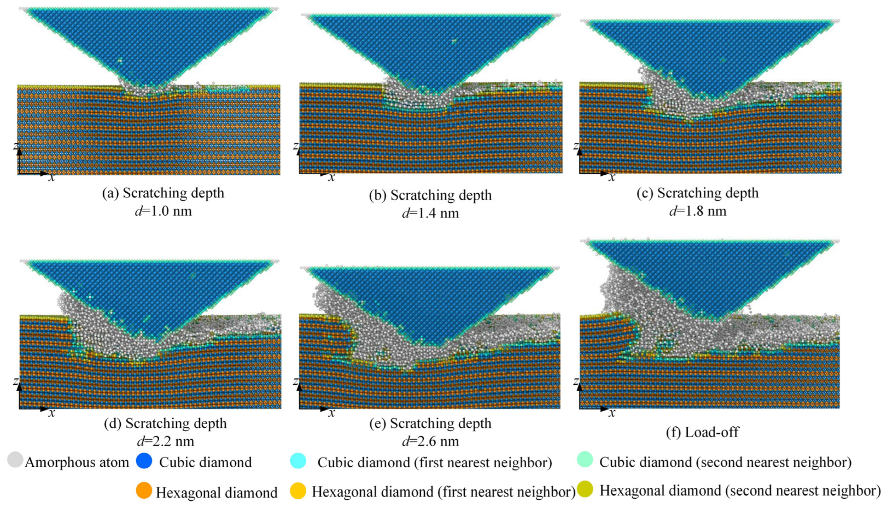
The tool contacts with single-crystal SiC, and single-crystal SiC atoms begin to deform under the squeezing effect of the tool. In the initial stage of contact between tool atoms and workpiece atoms, the contact area is small, and only a few workpiece atoms are subjected to tool compression. Therefore, during the nano scratch process, the elastic deformation of the workpiece is not significant as shown in Figure 2a. as the scratching depth increases, there are obvious amorphous chip atoms appearing as shown in Figure 2b–f. This is because in the process of scratching, the contact area between the tool and the workpiece gradually increases, the strain energy inside the workpiece lattice increases, and the atomic bond of single-crystal SiC breaks. The workpiece undergoes plastic deformation under the squeezing action of the tool, and the atoms in the shear zone of the workpiece slide upwards along the front-end face of the tool, forming amorphous chips. The atoms that slide downwards are squeezed by the tool tip, forming amorphous machining surface. From Figure 2, it can be seen that the atoms on the processed surface are arranged in disordered manner, and the crystal structure of the processed surface is damaged under the action of pressure and friction.
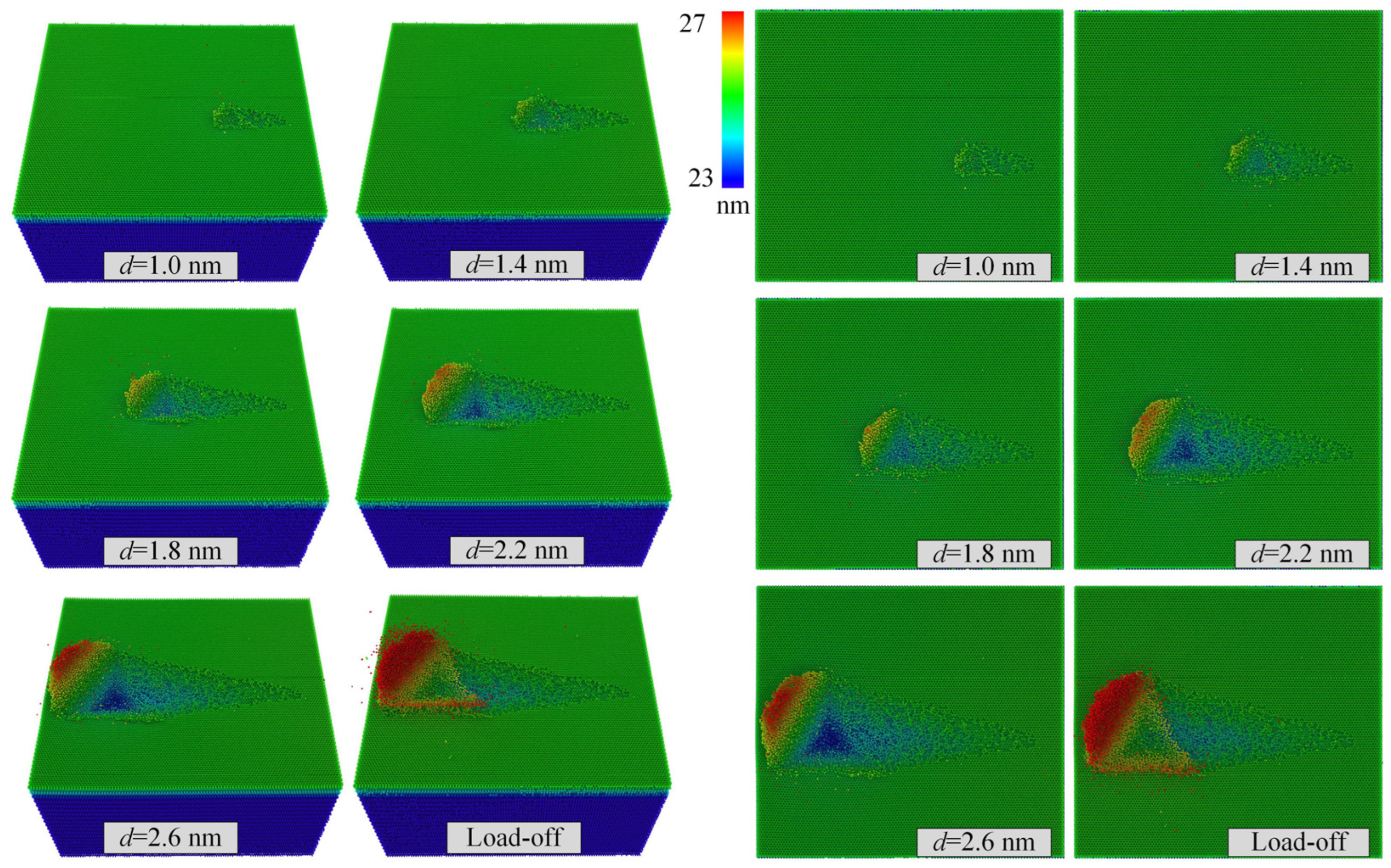
Hiding the Berkovich indenter tool, the instantaneous atomics positions on the workpiece surface are extracted at six moments after the load is removed. The scratching direction is 0°, and the scratching depths are 1.0 nm, 1.4 nm, 1.8 nm, 2.2 nm, 2.6 nm, respectively. The surface morphology of single-crystal 4H-SiC nano scratches at different times is obtained, as shown in Figure 3, and the color bar in Figure 3 shows the height of the removal atoms. When the scratching depth is small, as shown in Figure 3 with d = 1.0 nm, chip atoms can be seen in the direction of the tool scratching, but the material accumulation is not obvious. As the depth of tool scratching increases, the accumulation of chip atoms becomes more and more obvious, as shown in Figure 3 with d = 2.6 nm. By observing the surface of the workpiece after scratching, it can be observed that when the scratching direction is 0°, the removed chip atoms mainly accumulate on the edge of one side of the tool.
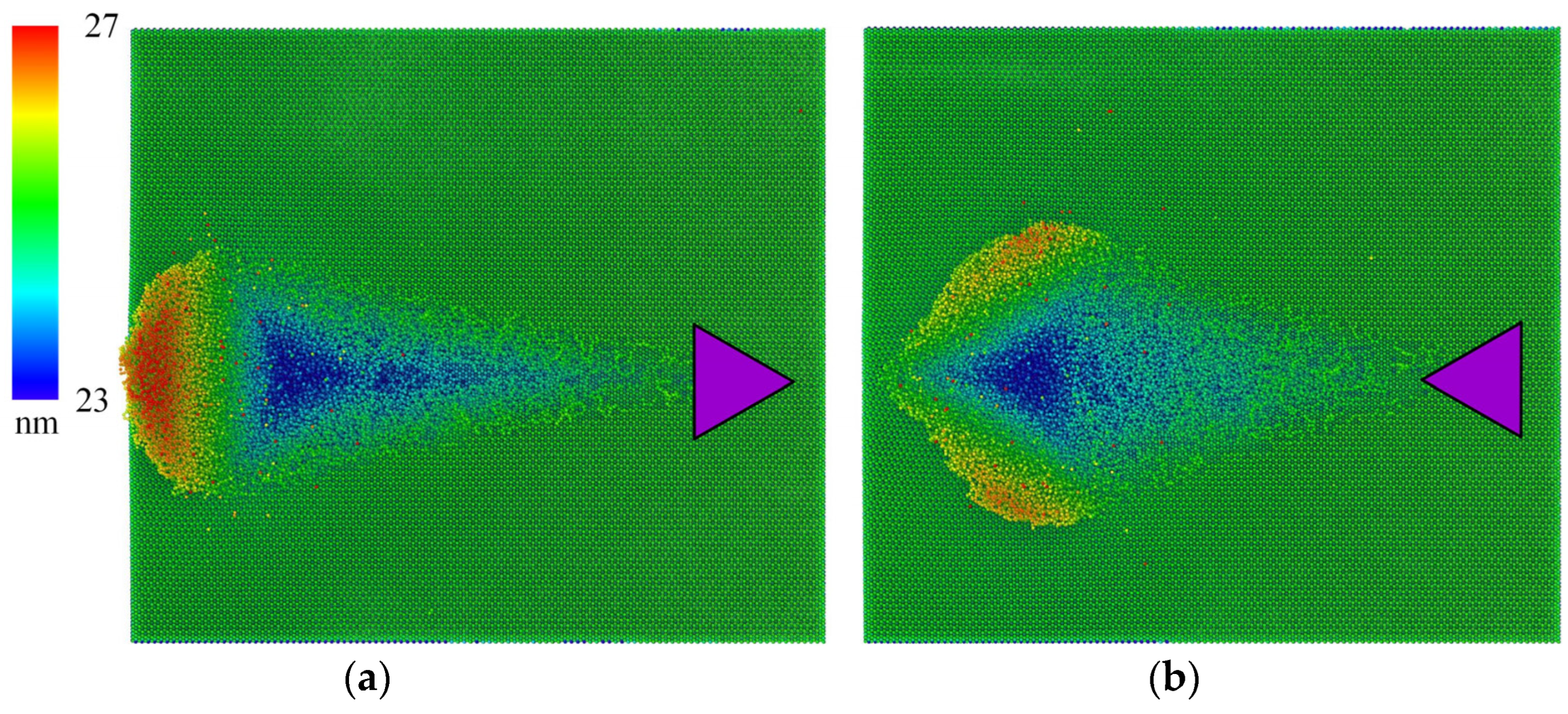
Extract the instantaneous atomics positions on workpieces surface in scratching directions of 30° and 90° and scratching depth of 2.6 nm, and obtain the surface morphology of nano scratches, as shown in Figure 4, and the color bar shows the height of the removal atoms. When the scratching direction is 30°, the atoms removed from the material accumulate at the front end of the tool, while when the scratching direction is 90°, the atoms removed from the material accumulate on both sides of the tool. By comparing the surface of the workpiece with different scratching angles of 0°, 30°, and 90°, it is shown that the different scratching directions of the scratching tool result in different directions of material accumulation after removal.
Extract the atomics number of chips in different scratching directions of the tool to study the material removal rate, and in order to avoid the influence of workpiece atoms on the results, count the atomics number above the surface of the workpiece. When the scratching direction is different, the atoms number of 4H-SiC single-crystal chips with the scratching depth is shown in Figure 5. When the scratching direction is 30°, the number of 4H-SiC single-crystal chips atoms is much greater than the chips atoms number at the scratching direction of 0° and 90°. The results indicate that under the same scratching depth, the material removal amount is greater when the direction of tool is 30°.

3.2. The Influence of Tool Scratching Direction on Material Surface Damage

Further study the mechanism of removing nano scratch materials from 4H-SiC single-crystal workpieces, and use dislocation extraction algorithms to identify dislocations in the internal atoms of the scratched 4H-SiC single-crystal workpieces, in order to characterize the slip characteristics of the internal atoms. As shown in Figure 6, three different perspectives are used to observe the workpiece after scratching. Figure 6a shows the front view of chips atoms and workpiece damage layer, Figure 6b shows the front view of the hidden damage atoms and the damage layer obtained after translucency of the defect grid, and Figure 6c is the vertical view after the same processing as Figure 6b.
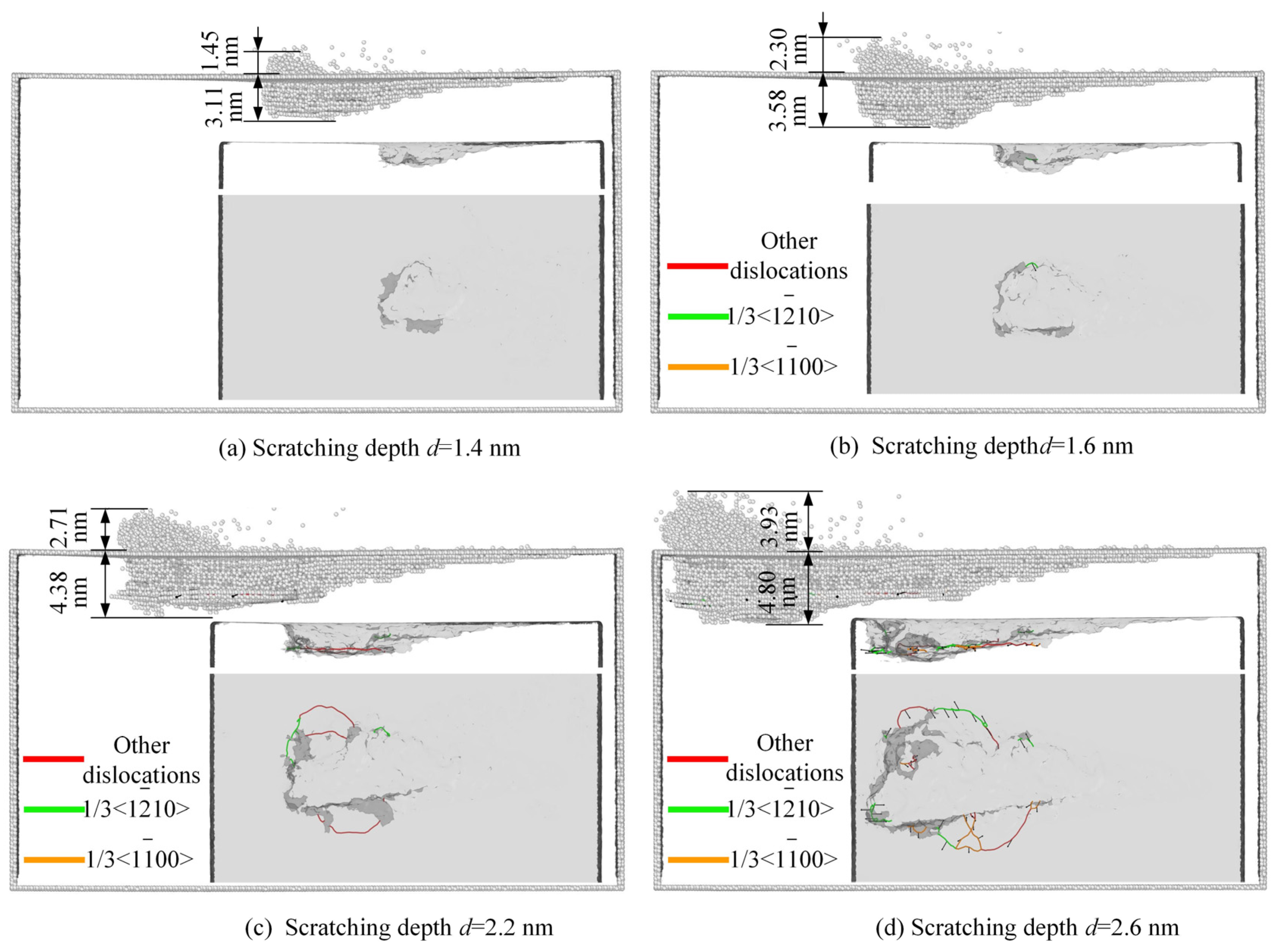
The recognition of dislocations in 4H-SiC single crystal (with crystal atoms removed) at depths of 1.4 nm, 1.6 nm, 2.1 nm, and 2.6 nm is shown in Figure 7 (Each image is a combination of the three perspectives shown in Figure 6). When the depth of the tool is shallow, such as d = 1.4 nm, the atoms of the 4H-SiC single-crystal workpiece are mainly atomic defects and amorphous plastic deformation, and no dislocations are found on the subsurface of the workpiece. When the scratch depth is 1.6 nm, the workpiece is in the early stage of plastic deformation, and the atoms of the workpiece are mainly removed through amorphous atomization, resulting in a very small amount of complete dislocations with a Burges vector of 1/3<1 2 ¯ 10>. When the scratch depth reaches 2.1 nm, the number of subsurface dislocations increases in single-crystal 4H-SiC. When the scratching depth reaches 2.6 nm, a large number of complete dislocations with a Burges vector of 1/3<1 2 ¯ 10> appear on the subsurface of single-crystal 4H-SiC, mainly expanding on the (0001) plane.
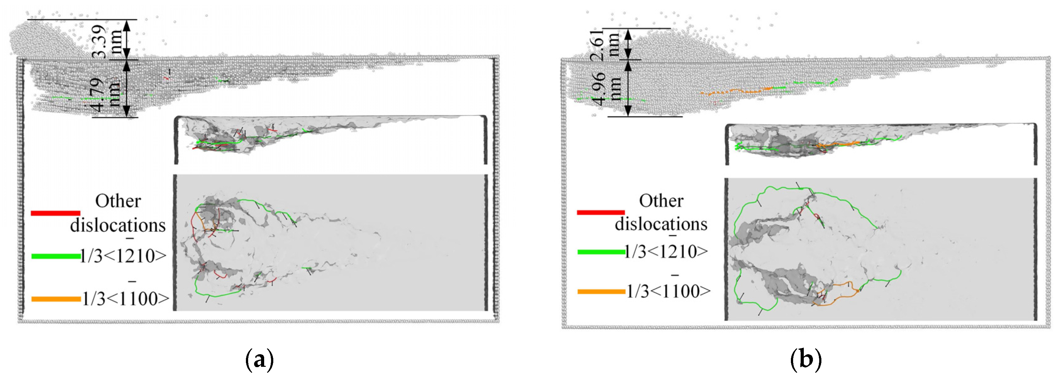
Comparing the subsurface dislocations in different scratching directions of the tool, the dislocation extraction method is used for the 30° and 90° scratching directions of the tool, and the dislocation recognition diagram at scratching depth d = 2.6 nm is obtained as shown in Figure 8. Compared with the number of dislocations at the depth of 2.6 nm, the number of dislocations at tool direction of 30° is significantly less than that at 0° and 90°. When the scratching directions of the tool are 0°, 30°, and 90°, the total length of dislocations extracted are 51.5 nm, 25.4 nm, and 52.36 nm, respectively. It also indicates that the dislocation is the least when the scratching direction of the tool is 30°. From Figure 7 and Figure 8, it can be seen that when the scratching depth is 2.6 nm, the thickness of the damage layer on the workpiece in different scratching directions is different. When the scratching direction of the tool is 30°, the workpiece damage layer is the thinnest. However, the difference in the three directions is small, it shows that the impact of different scratching directions of the tool on the damage layer is relatively small.

3.3. The Influence of Tool Scratching Direction on Scratching Force

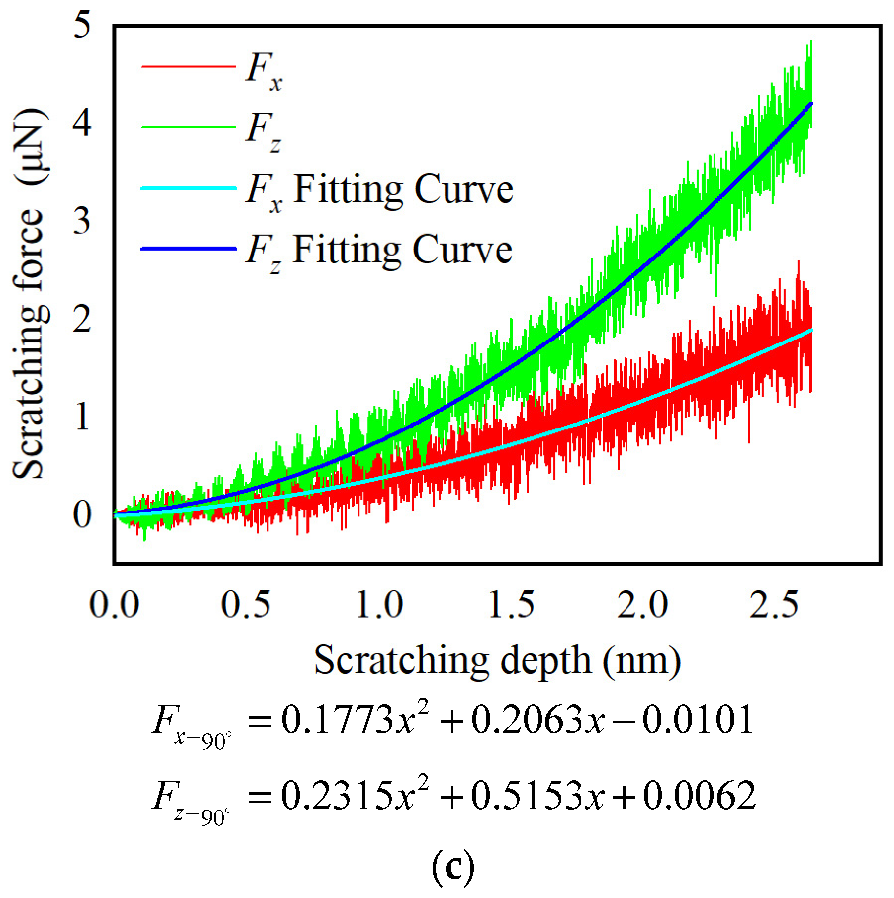
Scratching force is one of the most important parameters in macro scratching processing. Due to its ease of direct measurement, it is often achieved by controlling the scratching force to control other parameters. Molecular dynamics nano scratching force is different from traditional continuous medium processing models. It mainly comes from the interaction between tool atoms and workpiece atoms. The combined force of all tool atoms and workpiece atoms is decomposed in the X, Y, and Z directions to obtain tool tangential force, lateral force, and normal force, denoted as Fx, Fy, and Fz. During the scratching process, more attention is paid to tangential and normal forces (Fx and Fz). In this study, the values of tangential and normal scratching forces are output every 20 steps. The curve of force variation and fitting results are shown in Figure 9. From Figure 9, it can be seen that the variation trend of the scratching force is basically consistent under different scratching directions of tool. During the oblique scratching process of the tool, more and more atoms come into contact with the workpiece, and the tangential and normal forces increase with the increase in the scratching depth. This is because the indenter moves along the X direction while pressing into the workpiece (Z direction), as the forces in both directions increase and the trend of change is similar. This is consistent with the results of research [38]. This increasing trend has obvious fluctuation characteristics, and the initial fluctuation is small. As the scratching depth increases, the fluctuation becomes more obvious. This is because as the depth of the scratching tool increases, the lattice of the workpiece atoms at the front and bottom of the tool is destroyed, and the workpiece atoms slip under the squeezing effect of the tool, causing drastic changes in tangential and normal forces.
Comparing the scratching force in the three directions of the tool in Figure 9, the x direction is the direction in which the tool scratches. When the scratching depth is 2.64 nm, the scratching angles of the tool are 0°, 30°, and 90°, and their Fx are 1.82 μN, 2.02 μN, and 1.79 μN, respectively. The tool scratches into the workpiece at different angles, and the difference in the X direction cutting force is relatively small. However, the scratching force Fz of 30° is smaller than that of 0° and 90°, and the Z direction is the direction in which the tool is pressed down. When the scratching depth is 2.64 nm, the scratching angles of the tool are 0°, 30°, and 90°, and the Fz are 4.04 μN, 2.95 μN, and 4.26 μN, respectively. This is because when the scratching direction of the tool is 30°, the contact area between the front face of the tool and the workpiece is the smallest, and the atoms that the workpiece is subjected to compression and friction are also the least. A smaller scratching force is more advantageous in micro/nano mechanical processing.

3.4. The Influence of Tool Scratching Direction on Temperature

The average temperature distribution of the workpiece system after scratching is analyzed. From Figure 10a,b, it can be seen that atoms with high temperatures are mainly distributed in the chips and extrusion deformation area, which is consistent with the research [39]. There are fewer chip atoms in 10c, mainly because when the cross-section is along the centerline of the scratch and the tool direction is 90°, the chips are mainly concentrated on both sides of the tool. However, in Figure 10c, it can still be seen that the temperature in the extruded deformation area is relatively high. The high temperature in the chip area is due to the chip leaving the workpiece, hindering the progress of the tool and generating mutual forces with the tool. As the tool moves, it produces a certain displacement, resulting in a higher temperature. The temperature in the extruded deformation area is lower than that of the chip and higher than that of other parts of the workpiece, because the deformation area produces dislocation damage under the action of the tool, which directly contacts the tool, causes friction, and has a higher temperature. Lower than the chip temperature is because the area does not move with the movement of the tool. When in contact with the tool, the temperature in the area increases due to the force, and when the tool leaves, it no longer continues to rise, so the temperature is lower than the chip temperature.
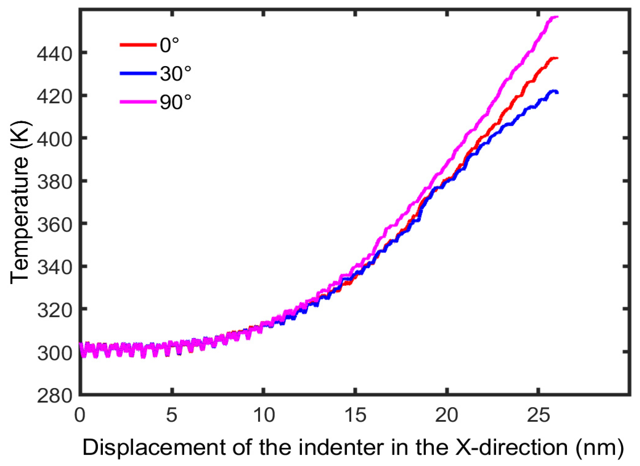
Compare the temperatures for different scratching directions of the tool, as shown in Figure 11. During the initial scratching stage (scratching displacement less than 10 nm), the temperature of the workpiece in all three directions remained almost unchanged. As the scratching progresses, the temperature varies, with the tool having the highest temperature at 90° in the scratching direction and the lowest at 30°. This is consistent with the comparison of scratching forces analyzed in Section 3.3, as force and temperature are related quantities, and the interaction force between the workpiece and the tool can affect the temperature. When the cutting force is large, higher temperatures will be generated.

4. Conclusions

This article establishes a molecular dynamics simulation model for nano scratches on 4H-SiC single crystals, studies the formation process of chips on the surface of SiC single crystals and the mechanism of material removal during the oblique scratching process with a Berkovich indenter, and analyzes the influence of tool scratching direction on nano scratches. Based on the research content of this article, the following conclusions are drawn:
  • The removal form of 4H-SiC single crystal at the nanoscale is mainly amorphous chips, forming an amorphous machined surface. The scratching angle of the tool is different, and the stacking position of chip atoms is different. Chip atoms of 0° and 30° are stacked on one side of the tool edge, while chip atoms of 90° are stacked on both sides of the tool.
  • When the scratching depth is small, the atoms of 4H-SiC single-crystal workpiece are mainly characterized by atomic defects and amorphous plastic deformation, and no dislocations are found on the subsurface of the workpiece. As the scratching depth increases, a large number of complete dislocations with a Burges vector of 1/3<1 2 ¯ 10> appear on the subsurface of 4H-SiC single crystal, mainly extending on the (0001) plane, leading to the plastic removal of the material.
  • Through the analysis of different scratching directions of the Berkovich indenter tool, it is found that a smaller rake angle not only reduces the scratching force during the scratching process, but also reduces the subsurface damage layer and workpiece temperature. The selection of scratching tools in the process of nano precision machining has certain significance.

Author Contributions

Conceptualization, L.L. and P.C.; methodology, P.C.; validation, S.L. and L.L.; investigation, P.C., K.L. and R.Y.; resources, S.L.; data curation, R.Y. and L.L.; writing—original draft preparation, L.L. and K.L.; writing—review and editing, L.L., R.Y. and S.L.; visualization, L.L.; supervision, S.L.; project administration, S.L. All authors have read and agreed to the published version of the manuscript.

Funding

The research was funded by the National Natural Science Foundation of China (No. 51575442) and the Shaanxi Province Key Research and Development Plan Project of China (Grant No. 2021GY-275).

Institutional Review Board Statement

Not applicable.

Informed Consent Statement

Not applicable.

Data Availability Statement

All data generated or analyzed during this study are included in this published article.

Acknowledgments

The authors wish to acknowledge the financial support for this work from the National Natural Science Foundation of China (No. 51575442) and the Shaanxi Province Key Research and Development Plan Project of China (Grant No. 2021GY-275).

Conflicts of Interest

The authors declare no conflict of interest.

References

  1. Liang, Y.C.; Li, Y.E.; Liu, Y.H.; Kuo, J.F.; Cheng, C.W.; Lee, A.C. High-quality structures on 4H-SiC fabricated by femtosecond laser LIPSS and chemical etching. Opt. Laser Technol. 2023, 163, 109437. [Google Scholar] [CrossRef]
  2. Wen, Q.; Yang, Y.; Lu, J.; Huang, H.; Cui, C. Study on picosecond laser stealth dicing of 4H-SiC along [1120] and [1100] crystal orientations on Si-face and C-face. Opt. Laser Technol. 2023, 162, 109300. [Google Scholar] [CrossRef]
  3. Sun, S.; Peng, X.; Xiang, H.; Huang, C.; Yang, B.; Gao, F.; Fu, T. Molecular dynamics simulation in single crystal 3C-SiC under nanoindentation: Formation of prismatic loops. Ceram. Int. 2017, 43, 16313–16318. [Google Scholar] [CrossRef]
  4. Jabbari, F.; Rajabpour, A.; Saedodin, S. Thermal conductivity and viscosity of nanofluids: A review of recent molecular dynamics studies. Chem. Eng. Sci. 2017, 174, 67–81. [Google Scholar] [CrossRef]
  5. Farajpour, A.; Ghayesh, M.H.; Farokhi, H. A review on the mechanics of nanostructures. Int. J. Eng. Sci. 2018, 133, 231–263. [Google Scholar] [CrossRef]
  6. Hollingsworth, S.A.; Dror, R.O. Molecular Dynamics Simulation for All. Neuron 2018, 99, 1129–1143. [Google Scholar] [CrossRef] [Green Version]
  7. Liu, X.; Shi, D.; Zhou, S.; Liu, H.; Liu, H.; Yao, X. Molecular dynamics simulations and novel drug discovery. Expert Opin. Drug Discov. 2018, 13, 23–37. [Google Scholar] [CrossRef]
  8. Wang, H.; Qu, Z.; Yin, Y.; Bai, J.; Yu, B. Review of Molecular Simulation Method for Gas Adsorption/desorption and Dif-fusion in Shale Matrix. J. Therm. Sci. 2018, 28, 1–16. [Google Scholar] [CrossRef]
  9. Venable, R.M.; Krämer, A.; Pastor, R.W. Molecular Dynamics Simulations of Membrane Permeability. Chem. Rev. 2019, 119, 5954–5997. [Google Scholar] [CrossRef] [PubMed]
  10. Zhou, Y.; Huang, Y.; Li, J.; Lv, W.; Zhu, F. Polishing process of 4H-SiC under different pressures in a water environment. Diam. Relat. Mater. 2023, 133, 109710. [Google Scholar] [CrossRef]
  11. Ito, H.; Kuwahara, T.; Kawaguchi, K.; Higuchi, Y.; Ozawa, N.; Kubo, M. Tight-binding quantum chemical molecular dynamics simulations for the elucidation of chemical reaction dynamics in SiC etching with SF6/O2 plasma. Phys. Chem. Chem. Phys. 2016, 18, 7808–7819. [Google Scholar] [CrossRef]
  12. Morishita, T.; Kayanuma, M.; Nakamura, T.; Kato, T. Cooperative Reaction of Hydrogen-Networked Water Molecules at the SiC–H2O2 Solution Interface: Microscopic Insights from Ab Initio Molecular Dynamics. J. Phys. Chem. 2022, 126, 12441–12449. [Google Scholar] [CrossRef]
  13. Rajendran, A.; Takahashi, Y.; Koyama, M.; Kubo, M.; Miyamoto, A. Tight-binding quantum chemical molecular dynamics simulation of mechano-chemical reactions during chemical–mechanical polishing process of SiO2 surface by CeO2 particle. Appl. Surf. Sci. 2005, 244, 34–38. [Google Scholar] [CrossRef]
  14. Noreyan, A.; Amar, J. Molecular dynamics simulations of nanoscratching of 3C SiC. Wear 2008, 265, 956–962. [Google Scholar] [CrossRef] [Green Version]
  15. Goel, S.; Luo, X.; Agrawal, A.; Reuben, R.L. Diamond machining of silicon: A review of advances in molecular dynamics simulation. Int. J. Mach. Tools Manuf. 2015, 88, 131–164. [Google Scholar] [CrossRef] [Green Version]
  16. Goel, S.; Luo, X.; Reuben, R.L.; Rashid, W.B. Atomistic aspects of ductile responses of cubic silicon carbide during nanometric cutting. Nanoscale Res. Lett. 2011, 6, 589. [Google Scholar] [CrossRef] [Green Version]
  17. Goel, S.; Luo, X.; Reuben, R.L. Molecular dynamics simulation model for the quantitative assessment of tool wear during single point diamond turning of cubic silicon carbide. Comput. Mater. Sci. 2012, 51, 402–408. [Google Scholar] [CrossRef]
  18. Goel, S.; Luo, X.; Reuben, R.L. Shear instability of nanocrystalline silicon carbide during nanometric cutting. Appl. Phys. Lett. 2012, 100, 231902. [Google Scholar] [CrossRef]
  19. Luo, X.; Goel, S.; Reuben, R.L. A quantitative assessment of nanometric machinability of major polytypes of single crystal silicon carbide. J. Eur. Ceram. Soc. 2012, 32, 3423–3434. [Google Scholar] [CrossRef] [Green Version]
  20. Goel, S.; Stukowski, A.; Luo, X.; Agrawal, A.; Reuben, R.L. Anisotropy of single-crystal 3C–SiC during nanometric cutting. Model. Simul. Mater. Sci. Eng. 2013, 21, 065004. [Google Scholar] [CrossRef]
  21. Xiao, G.; To, S.; Zhang, G. Molecular dynamics modelling of brittle–ductile cutting mode transition: Case study on silicon carbide. Int. J. Mach. Tools Manuf. 2015, 88, 214–222. [Google Scholar] [CrossRef]
  22. Xiao, G.; To, S.; Zhang, G. The mechanism of ductile deformation in ductile regime machining of 6H SiC. Comput. Mater. Sci. 2015, 98, 178–188. [Google Scholar] [CrossRef]
  23. Hanashiro, T.; Saitoh, K.I.; Sato, T.; Nishimura, K.; Takuma, M.; Takahashi, Y. Molecular Dynamics Study on Ductile Behavior of SiC during Nanoindentation. Tribol. Online 2016, 11, 183–188. [Google Scholar] [CrossRef] [Green Version]
  24. Zhu, B.; Zhao, D.; Tian, Y.; Wang, S.; Zhao, H.; Zhang, J. Study on the deformation mechanism of spherical diamond indenter and its influence on 3C-SiC sample during nanoindentation process via molecular dynamics simulation. Mater. Sci. Semicond. Process. 2019, 90, 143–150. [Google Scholar] [CrossRef]
  25. Zhu, B.; Zhao, D.; Zhao, H. A study of deformation behavior and phase transformation in 4H-SiC during nanoinden-tation process via molecular dynamics simulation. Ceram. Int. 2019, 45, 5150–5157. [Google Scholar] [CrossRef]
  26. Meng, B.; Yuan, D.; Xu, S. Study on strain rate and heat effect on the removal mechanism of SiC during nano-scratching process by molecular dynamics simulation. Int. J. Mech. Sci. 2019, 151, 724–732. [Google Scholar] [CrossRef]
  27. Meng, B.; Yuan, D.; Xu, S. Coupling effect on the removal mechanism and surface/subsurface characteristics of SiC during grinding process at the nanoscale. Ceram. Int. 2019, 45, 2483–2491. [Google Scholar] [CrossRef]
  28. Meng, B.; Yuan, D.; Xu, S. Atomic-Scale Characterization of Slip Deformation and Nanometric Machinability of Sin-gle-Crystal 6H-SiC. Nanoscale Res. Lett. 2019, 14, 309. [Google Scholar] [CrossRef] [PubMed]
  29. Meng, B.; Yuan, D.; Zheng, J.; Xu, S. Molecular dynamics study on femtosecond laser aided machining of monocrystalline silicon carbide. Mater. Sci. Semicond. Process. 2019, 101, 1–9. [Google Scholar] [CrossRef]
  30. Liu, Y.; Li, B.; Kong, L. Molecular dynamics simulation of silicon carbide nanoscale material removal behavior. Ceram. Int. 2018, 44, 11910–11913. [Google Scholar] [CrossRef]
  31. Tian, Z.; Xu, X.; Jiang, F.; Lu, J.; Luo, Q.; Lin, J. Study on nanomechanical properties of 4H-SiC and 6H-SiC by molecular dynamics simulations. Ceram. Int. 2019, 45, 21998–22006. [Google Scholar] [CrossRef]
  32. Zhou, P.; Shi, X.; Li, J.; Sun, T.; Zhu, Y.; Wang, Z.; Chen, J. Molecular dynamics simulation of SiC removal mechanism in a fixed abrasive polishing process. Ceram. Int. 2019, 45, 14614–14624. [Google Scholar] [CrossRef]
  33. Zhao, L.; Alam, M.; Zhang, J.; Janisch, R.; Hartmaier, A. Amorphization-governed elasto-plastic deformation under nanoindentation in cubic (3C) silicon carbide. Ceram. Int. 2020, 46, 12470–12479. [Google Scholar] [CrossRef]
  34. Sarikov, A.; Marzegalli, A.; Barbisan, L.; Scalise, E.; Montalenti, F.; Miglio, L. Molecular dynamics simulations of extended defects and their evolution in 3C–SiC by different potentials. Model. Simul. Mater. Sci. Eng. 2020, 28, 015002. [Google Scholar] [CrossRef]
  35. Nosé, S. A unified formulation of the constant temperature molecular dynamics methods. J. Chem. Phys. 1984, 81, 511–519. [Google Scholar] [CrossRef] [Green Version]
  36. Hoover, W.G. Canonical dynamics: Equilibrium phase-space distributions. Phys. Rev. A 1985, 31, 1695–1697. [Google Scholar] [CrossRef] [PubMed] [Green Version]
  37. Erhart, P.; Able, K. Analytical potential for atomistic simulations of silicon, carbon, and silicon carbide. Phys. Rev. B 2005, 71, 035211. [Google Scholar] [CrossRef] [Green Version]
  38. Chai, P.; Li, S.; Li, Y.; Yin, X. Study on Damage of 4H-SiC Single Crystal through Indentation and Scratch Testing in Micro–Nano Scales. Appl. Sci. 2020, 10, 5944. [Google Scholar] [CrossRef]
  39. Wu, Z.; Zhang, L.; Liu, W. Structural anisotropy effect on the nanoscratching of monocrystalline 6H-silicon carbide. Wear 2021, 476, 203677. [Google Scholar] [CrossRef]
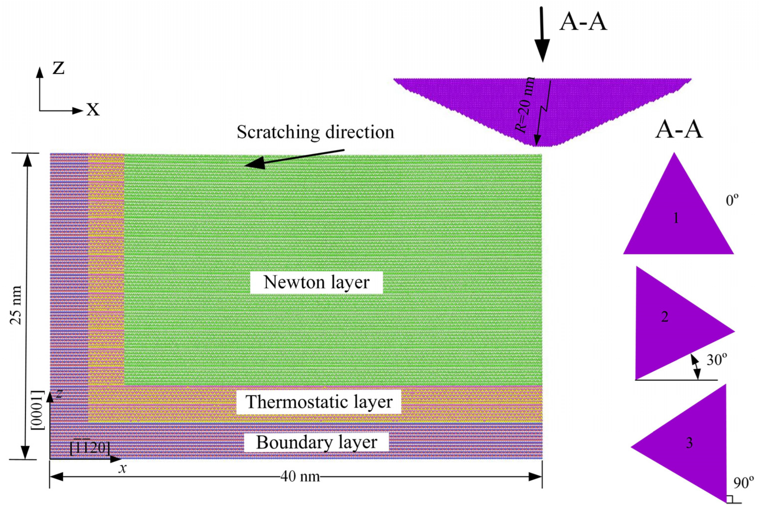
Figure 1. Scratch simulation model and scratch direction established by molecular dynamics.
Crystals 13 01044 g001
Figure 2. Crystal structure of 4H-SiC single crystal in different scratching depth.
Crystals 13 01044 g002
Figure 3. Instantaneous positions of atoms on workpiece surface in different scratching depths.
Crystals 13 01044 g003
Figure 4. Instantaneous atomics positions diagrams of 4H-SiC single crystal in different scratching direction. (a) Scratching direction of the tool is 30°. (b) Scratching direction of the tool is 90°.
Crystals 13 01044 g004
Figure 5. The chips atomics number in different scratching depths and dirrerent directions.
Crystals 13 01044 g005
Figure 6. Different perspectives for scratching results. (a,b) Front view. (c) Vertical view.
Crystals 13 01044 g006
Figure 7. Crystal structure of 4H-SiC single crystal in different scratching depths when the scratching direction is 0°.
Crystals 13 01044 g007
Figure 8. Crystal structure of 4H-SiC single crystal in different scratching direction (d = 2.6 nm). (a) Scratching direction of the tool is 30°. (b) Scratching direction of the tool is 90°.
Crystals 13 01044 g008
Figure 9. Scratching force variation curve of 4H-SiC single crystal in different scratching direction. (a) Scratching direction of tool is 0°. (b) Scratching direction of tool is 30°. (c) Scratching direction of tool is 90°.
Crystals 13 01044 g009aCrystals 13 01044 g009b
Figure 10. Cross-sections of temperature distribution along the scratching centerline. (a) Scratching direction of tool is 0°. (b) Scratching direction of tool is 30°. (c) Scratching direction of tool is 90°.
Crystals 13 01044 g010
Figure 11. Temperature change along the scratching displacement in X direction.
Crystals 13 01044 g011
Table 1. Comparison of the rake angle in different scratching directions of the tool.
Scratching Direction of the Tool30°90°
Vertical viewCrystals 13 01044 i001Crystals 13 01044 i002Crystals 13 01044 i003
Front viewCrystals 13 01044 i004Crystals 13 01044 i005Crystals 13 01044 i006
Rake angle α75.15°65.3°77.05°
Table 2. The ABOP potential function parameter table between Si and C [37].
ParameterSi-SiC-CSi-C
D0 (eV)3.246.004.36
r0 (Å)2.2221.42761.79
S1.5702.1671.847
β   ( Å 1 ) 1.47602.00991.6991
γ0.092530.112330.011877
c1.13681181.910273,987
d0.633976.28433180.314
h0.3350.55560.68
2 μ   ( Å 1 ) 000
R (Å)2.922.4
D (Å)0.150.150.2
Disclaimer/Publisher’s Note: The statements, opinions and data contained in all publications are solely those of the individual author(s) and contributor(s) and not of MDPI and/or the editor(s). MDPI and/or the editor(s) disclaim responsibility for any injury to people or property resulting from any ideas, methods, instructions or products referred to in the content.