Abstract
Friction Stir Extrusion (FSE), the focus of this research, is a process that has tremendous potential for shaping and improving the mechanical properties of the final product as well as the mechanical alloying. In this study, a cylindrical sample of LM13 aluminum, to which silicon powder is added, is extruded by the penetration of a tool and takes the shape of a tube. The microstructure of the aluminum tube produced is studied using a light microscope. Various tests, including compression and wear tests, are performed to evaluate the wear and mechanical properties of the tubes produced. Additionally, the process is simulated using the finite element method (FEM), and the strain and temperature distributions in the tubes are examined to understand the impact of tool advancing speed better. The strain and temperature are highest on the inner surface, where the tubes meet the tool. Moreover, as the advancing speed increases from 25 to 40 mm/min, the maximum temperature in the tubes increases from 350 to 400 °C. The surface quality of the samples is directly related to the advancing speed, so the surface quality improves as the advancing speed increases. The results obtained from the compression and wear tests show that the compression strength has increased by about 17%, and the wear resistance has improved by about 20%.
1. Introduction
Al-Si alloys are among the alloys that have caught the attention of researchers interested in modifying and increasing their performance due to their widespread use in industry, particularly the automobile industry [1,2,3]. Internal combustion engine components such as pistons are frequently made of these metals. To increase the performance of internal combustion engines, for example boosting their efficiency by increasing the compression ratio of these engines, it is necessary to improve the ability of these alloys to withstand high friction and temperatures. Despite their great wear resistance, defects in these alloys, such as dendritic structure, gaps, and non-uniformly spread acicular silicon particles, have made them unsuitable for various applications [4,5].
Casting is the most common method of producing commercial alloys. However, many alloys cannot be prepared using this method because the constituent parts have very different melting temperatures or vapor pressures, or because they are not soluble in liquid form [6]. For instance, the casting of LM28 alloy, which presents superior wear resistance properties compared to LM13, is challenging, and many cracks and flaws can be found in the casted parts of this alloy. It is necessary to employ other alloying techniques, such as mechanical alloying (MA), which circumvents many of the limitations of melting and casting for these alloys.
Heat treatment, stirring solidification, and modifier treatment are some of the procedures that have been developed to refine and enhance the microstructure of Al-Si cast alloys [7]. None of these methods can uniformly redistribute silicon particles throughout the aluminum matrix, eliminate faults such as porosity, or increase the strength or, in particular, the ductility of Al-Si alloys [8]. FSE can be used as a microstructural refining method for these alloys, improving their mechanical properties and wear resistance [3].
The friction stir extrusion process, a new method for producing fine-grained tubular materials, was developed in 2012 [9]. The main idea of this method is derived from the friction stir welding (FSW) process, which was first introduced in 1991 by The Welding Institute [10,11]. While developing this solid-state welding method, other friction processes were also developed. These methods have been used in applications such as improving the mechanical properties of materials, fabrication of surface composites, elimination of defects in the microstructure of materials, and mechanical alloying of metals. Sharifzadeh et al. [12] investigated the wear and corrosion resistance of magnesium wires produced using the FSE process. This research used three rotational speeds of 180, 250, and 355 rpm to produce the final sample. The test results showed that the extruded samples had a good surface quality, and this process is suitable for improving the hardness and abrasion resistance. These results indicate that FSE is an effective method for converting magnesium chips to usable wires. Tahmasbi et al. [13] investigated this process to produce AA7022 aluminum-wired specimens. The results showed that the surface quality of the samples produced with high rotational speeds and low extrusion forces is much better with fewer surface cracks. Bafari et al. [14] produced a metal-based composite wire using aluminum chips using FSE. In this study, different amounts of silicon carbide powder were used. They stated that increasing the amount of reinforcing powder causes intergranular sediments to form, affecting the quality of the extrusion process and causing cracks to open and non-uniform mechanical properties. Milner et al. [15] investigated the FSE process for producing fine-grained lightweight tubes. This work focused on measuring the effects of process parameters on the microstructure of materials. In this study, AZ31B-F magnesium billets were transformed into tubes by FSE. Their results showed that the yield strength of the base material is 211 MPa, while that of the sample produced by the FSE is 152 MPa, which means a 28% reduction in the yield strength. Ramesh et al. [16] produced heat tubes made of Ze41 magnesium alloy using FSE. Ze41 magnesium alloy was tested as a suitable material for making heat tubes because, in addition to being lightweight, magnesium tubes also have high thermal conductivity. The grain size of the raw material was reported to be about 85 microns, while it was 10 microns for the tube produced by FSE. Asadi et al. [17,18] used friction stir-back extrusion to produce brass wires from brass chips and developed a numerical model to simulate the process. They demonstrated the effects of process parameters, including tool rotational and advancing speed, on the strain and temperature distributions, microstructure, and material flow patterns, and concluded that, in the cross-section of the produced wire, the finer microstructure emerges in the sample periphery. Furthermore, they reported that a higher rotational speed or a lower advancing speed leads to a coarser microstructure, and the flow of materials near the tool axis is just upward while experiencing a significantly lower strain.
A review in the field of the FSE process shows that most of the researchers in this field have used the process only for the production of strong wires and tubes, and the discussion of mechanical alloying using this process and conversion of one alloy to another and its advantages have not been considered. Therefore, this research investigates the production of wear-resistant tubes of LM28 using mechanical alloying on the LM13 base alloy through the FSE method. The effects of the FSE tool advancing speed and mechanical alloying on the microstructure, Si particles size and aspect ratio, compression strength, hardness, and wear resistance are taken into consideration.
2. Experimental Procedure
The tools used in this process include two main parts of the rotating tool and the mold, and Figure 1 shows the schematic of this process for the production of tubes from a solid material. In step (1), the raw material (solid material) is placed inside the mold cavity while the looseness between it and the mold or special lock is designed at the bottom of the solid material, and the mold does not allow it to rotate and move. In step (2), the rotating tool, which is made of non-consumable alloy steel, penetrates the mold and contacts the upper edge of the sample. This step is to create friction preheating to allow the tool to penetrate the sample faster. In this case, the rotating tool is less pressurized. In step (3), the tool is advanced into the sample while the heat generated causes the raw material to soften. Then, the softened material is extruded upward as the tool moves down. In step (4), the tool continues to reach a predetermined depth and produce a tube of a special length. In step (5), the final shape of the tube is created by removing the tool from the matrix.
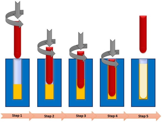
Figure 1.
Schematic representation of the FSE process.
The LM13 alloy is one of the most extensively utilized Al-Si series alloys in the automotive industry. The cast sample was produced as a rebar with a diameter of 25 mm in ambient conditions at a temperature of 25 °C and a humidity of 30%. The chemical composition test was performed by emission spectrometry, and its results are given in Table 1.

Table 1.
The weight percentage of the constituent elements of the raw material.
In this study, hot-rolled steel H13 was used to make a mold, and hot-rolled steel W360 was used to make the innovative tool. The geometric dimensions of the tool and the mold are illustrated in Figure 2. The inner hole of the mold is 25 mm, and its depth is 100 mm. The rotating tool is made of two parts:
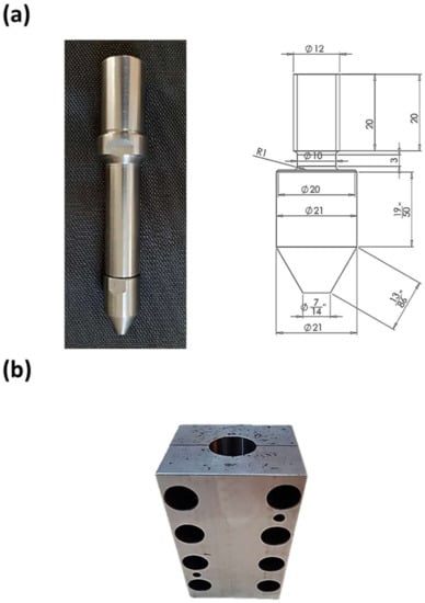
Figure 2.
(a) The rotating tool with its dimensions, (b) the matrix.
- The head, the more critical part, is in contact with the under-processing material, and its temperature will rise to 700–800 °C. Thus, it should be strict, rigid, and wear-resistant at high temperatures.
- The holder, which is connected to the rotating spindle of a milling machine and will experience lower temperatures and can be made of cheaper steel.
This tool design allows affordable replacement of the tool head after a period of production when its productivity is reduced. Figure 2a shows the assembled tool head and holder, along with the dimensions of the tool head. When the tools are made, a plasma nitration coating is applied to them to increase the surface hardness of the tools and reduce the friction and, thus, the adhesion probability between the tools and the hot raw material.
After the initial evaluation, a rotational speed of 630 rpm was selected as the desired rotational speed for this research. Advance velocities of 25, 31.5, and 40 mm/min were selected as the tool penetration rates into the mold cavity. Finally, using these parameters, three alloyed samples and three non-alloyed samples were produced so that a comparison could be made between them.
To perform mechanical alloying and conversion of LM13 to LM28 alloy, their constituent elements were used, a significant part of which is related to silicon. Then holes were made with the specified geometries in the whole depth of the billet, and the holes were filled and compressed with silicon powder. The as-cast ingot with holes for inserting the silicon particles along with the produced pipe sample is shown in Figure 3.
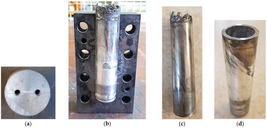
Figure 3.
The production steps of LM28 pipe using FSE: (a) primary as-cast LM13 with two holes which then will be filled by particles of alloying elements, (b) the produced pipe inside the mold when half of the mold is removed, (c) produced pipe by FSE, and (d) the undesired upper part is cut.
For microstructural observations on the optical microscope (OM), the tubes were cut perpendicular to their axis, and the cross-section was polished using a standard procedure. The standard compression test was carried out at the ambient temperature using a Cometech universal tensile/compression test machine at the strain rate of 10−3 s−1. The pipe length for performing the compression test was 25 mm. Two pipe samples are shown in Figure 4a after the compression test was performed. The dry wear test on the disk under the ASTM G99 standard was used to determine the wear resistance of the produced samples. The samples were cut from the pipe wall using the wire-cut process as shown in Figure 4b. The vertical force was 4.2 kg, and the linear velocity of the counterparts was 5 m/min for 1 km.
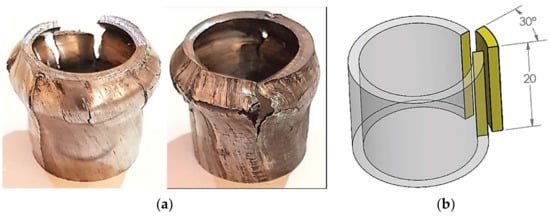
Figure 4.
(a) Two pipe samples after the compression test was performed, (b) schematic of wear test sample cut from the pipe wall for the dry pin on disk wear test.
3. Simulation Details
To thoroughly examine the process’s parameters, it is essential to be aware of the temperature distribution in the tubes throughout the procedure. When using experimental methods, obtaining the temperature distribution is difficult or even impossible due to the material’s significant deformation and the intense force being applied [19]. Deform-3DTM software, one of the best programs available for modeling processes with extreme plastic deformation, was utilized to simulate the FSE process. In this study, an arbitrary Lagrangian–Eulerian formulation was chosen to simulate the process numerically. The FSE tool was meshed with 32,000 tetrahedral elements and treated as a rigid body. Additionally, the workpiece was divided into two zones, and the mesh sizes varied. Smaller meshes of 0.8 mm are utilized on top of the workpiece, which experiences significant plastic deformation (Figure 5).
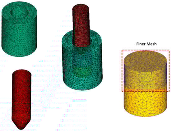
Figure 5.
Illustration of the workpiece and the FSE tool and mold for the numerical modeling.
The aluminum alloy flow stress is given as a function of strain rate, plastic strain, and temperature:
where represents the flow stress, represents the plastic strain, represents the strain rate, and T is the temperature.
This study modeled friction between the tool and workpiece using constant shear friction. The frictional force can be calculated as follows using the constant shear model:
where f, k, and m represent the frictional stress at the tool-workpiece interface, the shear yield stress, and the shear friction factor. In this research, the coefficient of friction was considered 0.35.
4. Results and Discussions
In the present study, the as-cast LM13 cylindrical cut samples were subjected to the FSE process, while for some samples, the alloying particles were inserted in the drilled holes to transform the LM13 to LM28. After the production of pipes, the samples were subjected to tests, including microstructural studies, compression tests, and wear tests, which are discussed in the following subsections.
4.1. Macro- and Micro-Structural Properties
Macroscopic images of the samples produced can be seen in Table 2. The results of macroscopic images show that in the area of the base metal (cast aluminum), some holes and pores, even in the LM13, are related to the casting process, but the FSE-processed areas, i.e., under the tool (stir zone) and the walls, are free of any defects or these defects are rarely present in these areas which can be omitted by process parameters optimization. A pit is only created in the area below the tool in the sample produced by the advancing speed of 31.5 mm/min and using particles, which may be due to the concentration of stress caused by the holes for embedding particles.
Table 2.
Macroscopic images of the samples produced by FSE.
Figure 6a schematically shows the cross-section of the FSE sample cut in the longitudinal axis of the pipe. Four different zones can be distinguished in this cross-section. When the FSE process is applied a bit far from the rotating tool head, the base material is available. This zone is introduced by 1 in Figure 6a, and its microstructure is presented in Figure 6b, which involves needle-like extensive precipitates mostly composed of Si and are scattered on the aluminum matrix heterogeneously. On the one hand, due to factors such as stress concentration, these coarse particles and their uneven dispersion in the aluminum impair the mechanical qualities of this alloy and increase the metal’s brittleness [20,21]. Other flaws found in the base metal include voids and α-Al dendrites. Silicon particles in the aluminum alloy have an average size of roughly 10 microns and a 4.92 aspect ratio. The aspect ratio of a geometric shape is the ratio of its sizes in different dimensions. For instance, the aspect ratio of a Si particle in this study is the ratio of its longer side to its width.
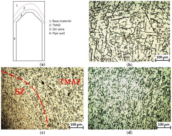
Figure 6.
(a) Schematic of the longitudinal cross-section for the pipe produced by FSE, (b) microstructure of the base metal, (c) microstructure of TMAZ and SZ, and (d) microstructure of pipe wall.
Moving closer to the tool head, part of the material somehow undergoes strain, plastic deformation, and higher temperature exposure, leading Si precipitates to be broken into smaller ones and reducing their aspect ratio. This zone is represented by 2 in Figure 6a and is called the Thermo-Mechanically Affected Zone (TMAZ). Although partially broken, the precipitates are aligned in a special direction toward the pipe wall, which will be discussed in further stages.
In the distance between the TMAZ and the tool head, there is the Stir Zone (SZ) which is represented by 3 in Figure 6a, and its microstructure along with the TMAZ are presented in Figure 6c. As can be seen, the precipitates are broken, and there is no sign of needle-like Si precipitates. In addition, due to the high temperature, which is near to 90% of the melting point, there is very severe plastic deformation in this zone and some parts of the precipitates are dissolute. Due to the high material flow induced in this area, the dendrites and cavities in the base metal structure have been eliminated. The creation of this microstructure eliminates the base metal’s underlying issues, and the mechanical properties are expected to improve.
By advancing the rotating tool inside the base material, the materials under process are conducted to the narrower channel of the pipe wall. When the diagonal part of the tool head finishes, the material plastic deformation reduces drastically, and there is a slight friction between the pipe inside and outside walls with the rotating tool and the mold. The majority of the microstructure in this zone, represented by 4 in Figure 6a, consists of an almost uniform distribution of fine circular Si particles in the aluminum matrix (Figure 6d).
Figure 7 illustrates the microstructure of produced pipe by FSE through the wall thickness. The Si particles and precipitates are finer in the zone toward the wall inside, and going toward the wall outside, the precipitates become coarser. Paying attention to Figure 12 (which will be discussed later), the strain value through the wall thickness has a reverse pattern, and its amount inside the pipe wall is much higher in comparison to its outside. Thus, the higher the strain value during FSE, the finer the Si particles and the smaller the precipitates.
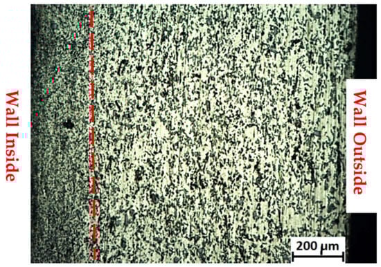
Figure 7.
Microstructural difference between pipe wall inside and outside zones.
The embedded alloying particles start to distribute over the aluminum matrix, as shown in Figure 8a. In this figure, the border of the SZ and TMAZ can somehow be seen by the swathe of inserted particles that are distributed. Going further from the stir zone toward the pipe wall zone (from the topside to the downside of Figure 8a) the embedded particles are distributed in a wider zone. Figure 8b shows this zone with higher magnification for more clarification.
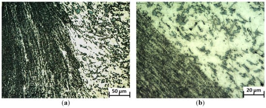
Figure 8.
(a) Microstructure of SZ and TMAZ for the specimens filled with Si particles for mechanical alloying, (b) Figure 8a in higher magnification.
Figure 9 compares the microstructure of the pipe wall zone for the specimens produced by FSE at different advancing speeds with and without alloying elements. Two major points can be detected from this figure:
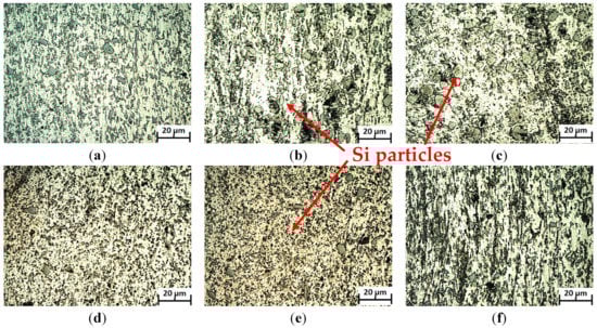
Figure 9.
Microstructure of pipe wall zone for the specimens produced by FSE with and without mechanical alloying. (a–c) specimens without mechanical alloying, and (d–f) specimens with mechanical alloying. Advancing speed was (a,d) 20 mm/min, (b,e) 31.5 mm/min, and (c,f) 40 mm/min.
- The first one is that the level of particle distribution uniformity becomes worse as the advancing speed rises for both alloyed and non-alloyed samples. Indeed, an increase in the advancing speed reduces the time in which the rotating tool sweeps the material by rotational movement in a constant length of pipe production. Therefore, the strain amount applied to the material decreases (as will be discussed in Figure 12), leading to worse distribution of alloying particles in the metal matrix. This weakened strain will result in a lower breakage and larger size of Si precipitates. The average size of Si precipitates in the Al matrix is shown in Figure 10. For instance, in the sample produced without alloying particles, the Si particle size increases from 1.4 µm for the sample with an advancing speed of 25 mm/min to 2 µm for the sample with an advancing speed of 40 mm/min.
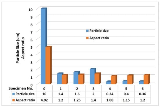 Figure 10. Si particle average size and aspect ratio in the base material and the pipe wall zone for the produced samples by FSE.
 - The addition of finer alloying elements in samples 4–6 reduced the average precipitate size drastically, and there is also no sign of large precipitates compared to the equivalent non-alloyed samples (for instance, compare Figure 9c,f). Adding finer alloying particles seems to have led to more breakage of primary precipitates during the FSE process.
Furthermore, the Si precipitates aspect ratio is presented in Figure 10. Although there is no significant difference in the aspect ratio of precipitates between the FSE samples, it is considerable when comparing the as-cast and FSE samples, as it is reduced from almost 5 for the as-cast metal to on average 1.2 for the FSE samples.
Figure 11 shows the effects of the tool advancing speed on the temperature distribution in the cross section of the tube produced by FSE. With an increase in advancing speed from 25 to 40 mm/min, the maximum temperature drops from 400 to 350 °C. Two opposing factors cause this temperature increase. Due to the increased force applied by the tool to the workpiece with increasing advancing speed, the heat generated by friction increases as well [22,23]. In contrast, increasing the advancing speed reduces the processing time and the time the workpiece is exposed to heat [24]. This figure shows that raising the advancing speed reduces the temperature of the workpiece, indicating that the processing time is the predominant factor determining the temperature.
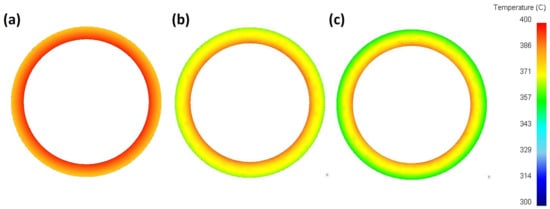
Figure 11.
Temperature distribution at the cross-section of the tube during the FSE process at the advancing speed of (a) 25 mm/min, (b) 31.5 mm/min, and (c) 40 mm/min.
An under-processed material undergoes plastic deformation characteristics, such as strain rate and effective strain, in addition to the high temperature and thermal cycle, which affect the tube microstructure and, as a result, the mechanical properties. The relation between effective strain and effective stress is widely described in the classic mechanic literature [25].
Additionally, the amount of strain applied to the material during friction-stir-based processes is significantly higher than that during other severe plastic deformation (SPD) techniques such as extrusion, high-pressure torsion, and equal channel angular processes. It is reported in the literature that the maximum effective strain is 2, 3, 5, and 28 for extrusion, equal channel angular process, equal channel angular extrusion, and high-pressure torsion [26,27,28], while its amount is not comparable with the friction-stir-based processes which present an effective strain of 50–200 [17,29,30].
Figure 12 depicts the distribution of strain in the cross-section of the tubes made at various tool advancing speeds. As is obvious, in all tubes, the strain is maximum on the inner surface where the tubes and the tool are in contact. In this area, the rotational speed of the tool causes a more severe flow of material and results in a higher strain. Then, the strain decreases as it goes towards the outer wall of the tube until it reaches its minimum value. As is shown, the strain experienced by the material increases when decreasing the advancing speed of the tool, which indicates an increase in the intensity of the material flow. In other words, decreasing the advancing speed increases the processing time, and the materials in the processing zone are under the plastic deformation for a longer time (since the rotational speed to advancing speed ratio (ɷ/v) is increased), and this results in a higher strain.
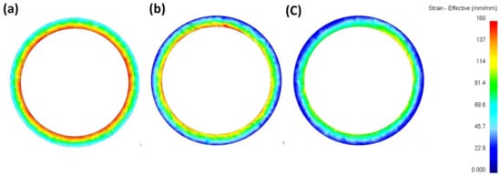
Figure 12.
The effective strain distribution at the cross-section of the tube during the FSE process at the advancing speed of (a) 25 mm/min, (b) 31.5 mm/min, and (c) 40 mm/min.
4.2. Mechanical Properties of the Tubes
The engineering stress-strain curves achieved from the compression test for samples produced by FSE are depicted in Figure 13. While the maximum compression strength obtained for the as-cast base material was almost 85 MPa, it is above 100 MPa for all processed samples. This shows that the FSE process improves the material strength by eliminating the drawbacks of the casting process.
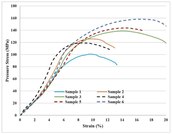
Figure 13.
The stress-strain curves achieved from the compression test for samples produced by FSE.
Investigating the values summarized in Table 3 for maximum compression strength and the strain at that point, one can understand that mechanical alloying by FSE and changing the process parameters can result in an improvement of almost 50% for the compression strength and 96% for the strain. Mechanical alloying of LM13 and transforming it to LM28 using the FSE method increased the compression strength of as-cast LM13 from 85 to 158.2 MPa for the mechanical alloyed LM28 at the advancing speed of 40 mm/min. This shows an almost 86% enhancement in compression strength. Although both FSE and mechanical alloying increased the mechanical properties of the produced samples, there is a crucial point. In the microstructural properties section, it was understood that a higher advancing speed results in a coarser precipitate and microstructure. While this coarser microstructure was expected to present lower mechanical properties, the higher advancing speed resulted in higher compression strength and strain for both alloyed and non-alloyed FSE samples. It may be attributed to the fact that higher advancing speed produces higher forging force, improves material integrity, and removes more flaws of the as-cast samples, leading to a higher compression strength.
Table 3.
The values of max. compression stress and its strain achieved for the samples produced by FSE.
Comparing the effects of FSE on the LM13′s mechanical properties with the effects of other processes, Hemanth and Arasukumar [31] produced an LM13/TiC composite by the addition of 3–9 wt.% of TiC to LM13 using stir casting and successfully improved the tensile strength from 155 MPa to at most 173 MPa. Rajamanickam and Uvaraja [32] also produced LM13 aluminum alloy hybrid metal matrix composites by varying the amount of titanium diboride (TiB2) from 0–15 wt.% and adding a constant 3 wt.% of boron carbide. They improved the ultimate tensile strength of LM13 from 151 to 192 MPa by reinforcing 15 wt.% of titanium diboride along with 3 wt.% of boron carbide particles.
It is worth mentioning that the ductility of the processed samples in comparison to the as-cast ones is drastically increased. In addition, by paying attention to the stress-strain curves in Figure 13 and comparing the area under the curves, it can be concluded that the ductility of the processed samples increases as the advancing speed of the FSE tool increases. Furthermore, the ductility in the alloyed samples is much more than that in the samples processed with the same advancing speed as the FSE tool but without alloying.
Indeed, the ductility of the LM13 as-cast alloy is improved through microstructural modifications such as the transformation of needle-like Si particles to circular-fine Si particles and the elimination of casting porosities as were available in the base material. Additionally, as discussed for the ultimate compression strength, it is expected that higher advancing speeds which present a finer microstructure and higher strength will also result in superior ductility.
4.3. Hardness and Wear Properties
The hardness and wear properties of the samples produced by FSE and the as-cast LM13 sample are considered through the standard microhardness and wear tests, and the results are summarized in Table 4.
Table 4.
Wear rate in the as-cast LM13 alloy and specimens produced by FSE with and without mechanical alloying.
The hardness value is almost low with the amount of 72 HV and the wear rate is significantly high for the as-cast sample due to the coarse microstructure and precipitates. The presence of the needle-like Si precipitates in the casted matrix deteriorates the hardness and wear properties. Applying the FSE process leads to uniform distribution of broken and almost circular Si particles in the aluminum matrix, resulting in a finer microstructure and consequently higher hardness and wear resistance as these particles act as bearings during the sliding of the sample on the counterpart. Reducing the advancing speed for both the alloyed and non-alloyed FSE samples leads to a better and finer particle distribution in the aluminum matrix, which improves the hardness and wear resistance of the material and makes the separation of precipitates over the sliding harder.
It is worth mentioning that the effect of FSE process parameters on the hardness and wear resistance is more significant for the alloyed samples rather than the non-alloyed ones. Although embedding the Si particles as alloying elements inside the as-cast LM13 is effective in hardness and wear resistance improvement, the uniform distribution of alloying elements is more crucial. The effect of advancing speed reduction from 40 to 25 mm/min on the wear rate reduction is almost 18.5% for the alloyed samples, while it is almost 13.4% for the non-alloyed ones.
5. Conclusions
In the process of friction stir extrusion, rotational speed and forward speed are two influential factors. Based on trial and error in the initial tests, it was concluded that the samples had the best quality at a rotational speed of 630 rpm compared to other rotational speeds. Then, with the constant rotational speed and different advancing speeds, the steps of this research were carried out, and the following results were obtained:
- At a constant rotational speed, the quality of the outer surface of the tube improves due to the increase in extrusion pressure as the advancing speed increases.
- The optical microscopy considerations reveal that in the stirring zone, the extended precipitates undergo severe breakage and become very fine in an almost circular shape. The size of silicon particles in LM13 decreased from 10 to almost 1.6 µm on average just by applying the FSE process. The addition of alloying elements for transforming LM13 to LM28 led to more breakage of the precipitates over the process, and since their primary size is around 200 nm, the average Si size dropped below 0.4 µm for the LM28 samples.
- The compression test results show that the FSE process improves the compression strength of as-cast LM13, depending on the process parameters, from almost 19 to 63%. Increasing the advancing speed improves the compressive strength of FSE pipes through the more severe forging force during the process. Additionally, the alloyed FSE specimens (LM28 samples) have higher compressive strength than the non-alloyed ones (LM13) and show an average of 17% improvement in strength.
- The wear resistance of as-cast LM13 alloy can be improved by an average of 18% by applying the FSE process. Furthermore, an extra improvement of 20% (on average) on the wear resistance can be achieved by the addition of alloying elements and transforming to LM28.
- During FSE the temperature of the under-process material rises due to the frictional heat and plastic deformation. The maximum temperature occurs in the stir zone and inside the wall thickness where the tube and the rotating tool are in contact. Reducing the advancing speed from 40 to 25 mm/min increases this maximum temperature from 350 to 400 °C.
- Similar results have been found for the strain distribution, as the maximum strain occurs in the inside wall of the tube and its value increases as the advancing speed decreases. This is because, at a lower advancing speed, the material under process experiences more movement over a constant period.
- Because of the greater strain on the inner wall of the pipe, the precipitates are much finer at approximately 1/5 of the inner wall thickness.
Author Contributions
Conceptualization, P.A., M.A.; Data curation, P.A., M.A., M.T., M. P.; Formal analysis, P.A., M.A., T.S., M.R.M.A.; Funding acquisition, P.A.; Investigation, P.A., M.A., M.T., M.P.; Methodology, P.A., M.A., T.S., M.R.M.A.; Project administration, P.A., T.S., M.R.M.A.; Resources, P.A., M.A., T.S., M.R.M.A.; Software, M.A.; Supervision, P.A., M.A., T.S.; Validation, P.A., M.A., M.R.M.A.; Visualization, P.A., M.A., T.S.; Writing—original draft, P.A., M.A., M.T., M.P.; Writing—review & editing, P.A., M.A., T.S., M.R.M.A. All authors have read and agreed to the published version of the manuscript.
Funding
This research received no external funding.
Data Availability Statement
The data presented in this study are available on request from the corresponding author.
Conflicts of Interest
The authors declare no conflict of interest.
References
- Rafieazad, M.; Mohammadi, M.; Gerlich, A.; Nasiri, A. Enhancing the corrosion properties of additively manufactured AlSi10Mg using friction stir processing. Corros. Sci. 2021, 178, 109073. [Google Scholar] [CrossRef]
- Mehrian, S.S.M.; Rahsepar, M.; Khodabakhshi, F.; Gerlich, A.P. Effects of friction stir processing on the microstructure, mechanical and corrosion behaviors of an aluminum-magnesium alloy. Surf. Coat. Technol. 2021, 405, 126647. [Google Scholar] [CrossRef]
- Pietras, D.; Sadowski, T.; Boniecki, M.; Postek, E. Experimental Testing of Al-Si12/SiC Interpenetrating Composites (IPC) in Uniaxial Tension and Compression. Arch. Metall. Mater. 2023, 68, 145–154. [Google Scholar] [CrossRef]
- Ajay Kumar, P.; Madhu, H.C.; Pariyar, A.; Perugu, C.S.; Kailas, S.V.; Garg, U.; Rohatgi, P. Friction stir processing of squeeze cast A356 with surface compacted graphene nanoplatelets (GNPs) for the synthesis of metal matrix composites. Mater. Sci. Eng. A 2020, 769, 138517. [Google Scholar] [CrossRef]
- Ma, L.; Zhou, C.; Shi, Y.; Cui, Q.; Ji, S.; Yang, K. Grain-Refinement and Mechanical Properties Optimisation of A356 Casting Al by Ultrasonic-Assisted Friction Stir Processing. Met. Mater. Int. 2021, 27, 5374–5388. [Google Scholar] [CrossRef]
- Ahmadkhaniha, D.; Asadi, P. 9—Mechanical alloying by friction stir processing. In Advances in Friction-Stir Welding and Processing; Givi, M.K.B., Asadi, P., Eds.; Woodhead Publishing: London, UK, 2014; pp. 387–425. [Google Scholar] [CrossRef]
- Choudhary, C.; Sahoo, K.L.; Mandal, D. Microstructure and mechanical properties of Al-Si alloys processed by strain induced melt activation. Mater. Today Proc. 2018, 5, 27107–27111. [Google Scholar] [CrossRef]
- Akbari, M.; Shojaeefard, M.H.; Asadi, P.; Khalkhali, A. Wear and mechanical properties of surface hybrid metal matrix composites on Al–Si aluminum alloys fabricated by friction stir processing. Proc. Inst. Mech. Eng. Part L J. Mater. Des. Appl. 2017, 233, 790–799. [Google Scholar] [CrossRef]
- Jahani, A.; Jamshidi Aval, H.; Rajabi, M.; Jamaati, R. Microstructures and properties of copper matrix composite wires reinforced with Ti2SnC particles. Mater. Sci. Technol. 2023, 1–17. [Google Scholar] [CrossRef]
- Amini, A.; Asadi, P.; Zolghadr, P. Friction stir welding applications in industry. In Advances in Friction-Stir Welding and Processing; Woodhead Publishing: London, UK, 2014; pp. 671–722. [Google Scholar] [CrossRef]
- Asadi, P.; Aliha, M.R.M.; Akbari, M.; Imani, D.M.; Berto, F. Multivariate optimization of mechanical and microstructural properties of welded joints by FSW method. Eng. Fail. Anal. 2022, 140, 106528. [Google Scholar] [CrossRef]
- Sharifzadeh, M.; Ansari, M.A.; Narvan, M.; Behnagh, R.A.; Araee, A.; Besharati Givi, M.K. Evaluation of wear and corrosion resistance of pure Mg wire produced by friction stir extrusion. Trans. Nonferrous Met. Soc. China 2015, 25, 1847–1855. [Google Scholar] [CrossRef]
- Tahmasbi, K.; Mahmoodi, M. Evaluation of microstructure and mechanical properties of aluminum AA7022 produced by friction stir extrusion. J. Manuf. Process. 2018, 32, 151–159. [Google Scholar] [CrossRef]
- Ingarao, G.; Baffari, D.; Reynolds, A.P.; Fratini, L.; Masnata, A. Friction stir extrusion to recycle aluminum alloys scraps: Energy efficiency characterization. J. Manuf. Process. 2019, 43, 63–69. [Google Scholar] [CrossRef]
- Milner, J.L.; Abu-Farha, F. Microstructural Evolution and Its Relationship to the Mechanical Properties of Mg AZ31B Friction Stir Back Extruded Tubes. In Magnesium Technology 2014; Alderman, M., Manuel, M.V., Hort, N., Neelameggham, N.R., Eds.; Springer International Publishing: Cham, Switzerland, 2016; pp. 263–268. [Google Scholar] [CrossRef]
- Ramesh, S.; Lakshminarayanan, A.K.; Raghavan, Y.; Harathi, Y. Fabrication and Numerical Analysis of Friction Stir Back Extruded Lightweight Magnesium Alloy Heat Pipes. Mater. Sci. Forum 2020, 979, 129–134. [Google Scholar] [CrossRef]
- Asadi, P.; Akbari, M. Numerical modeling and experimental investigation of brass wire forming by friction stir back extrusion. Int. J. Adv. Manuf. Technol. 2021, 116, 3231–3245. [Google Scholar] [CrossRef]
- Asadi, P.; Akbari, M.; Kohantorabi, O.; Peyghami, M.; Aliha, M.R.M.; Salehi, S.M.; Asiabaraki, H.R.; Berto, F. Characterization of the Influence of Rotational and Traverse Speeds on the Mechanical and Microstructural Properties of Wires Produced By the FSBE Method. Strength Mater. 2022, 54, 318–330. [Google Scholar] [CrossRef]
- Akbari, M.; Asadi, P. Dissimilar friction stir lap welding of aluminum to brass: Modeling of material mixing using coupled Eulerian–Lagrangian method with experimental verifications. Proc. Inst. Mech. Eng. Part L J. Mater. Des. Appl. 2020, 234, 1117–1128. [Google Scholar] [CrossRef]
- Hangai, Y.; Nakano, Y.; Utsunomiya, T.; Kuwazuru, O.; Yoshikawa, N. Drop Weight Impact Behavior of Al-Si-Cu Alloy Foam-Filled Thin-Walled Steel Pipe Fabricated by Friction Stir Back Extrusion. J. Mater. Eng. Perform. 2016, 26, 894–900. [Google Scholar] [CrossRef]
- Cheng, W.; Liu, C.Y.; Ge, Z.J. Optimizing the mechanical properties of Al–Si alloys through friction stir processing and rolling. Mater. Sci. Eng. A 2021, 804, 140786. [Google Scholar] [CrossRef]
- Al-Buainain, M.; Shunmugasamy, V.C.; Usman, C.A.; Mansoor, B. Influence of Microstructure on the Mechanical and Corrosion Response of a Friction Stir-Extruded WE43 Magnesium Rod. Metals 2023, 13, 191. [Google Scholar] [CrossRef]
- Wojcicka, A.; Mroczka, K.; Morgiel, J. Modification of Mechanical Properties of Aluminum Alloy Rods via Friction-Extrusion Method. Materials 2020, 13, 5224. [Google Scholar] [CrossRef]
- Zolghadr, P.; Akbari, M.; Asadi, P. Formation of thermo-mechanically affected zone in friction stir welding. Mater. Res. Express 2019, 6, 086558. [Google Scholar] [CrossRef]
- Hohe, J.; Becker, W. Effective stress-strain relations for two-dimensional cellular sandwich cores: Homogenization, material models, and properties. Appl. Mech. Rev. 2002, 55, 61–87. [Google Scholar] [CrossRef]
- Estrin, Y.; Molotnikov, A.; Davies, C.; Lapovok, R. Strain gradient plasticity modelling of high-pressure torsion. J. Mech. Phys. Solids 2008, 56, 1186–1202. [Google Scholar] [CrossRef]
- Ivanisenko, Y.; Kulagin, R.; Fedorov, V.; Mazilkin, A.; Scherer, T.; Baretzky, B.; Hahn, H. High Pressure Torsion Extrusion as a new severe plastic deformation process. Mater. Sci. Eng. A 2016, 664, 247–256. [Google Scholar] [CrossRef]
- Tayebi, P.; Fazli, A.; Asadi, P.; Soltanpour, M. Formability study and metallurgical properties analysis of FSWed AA 6061 blank by the SPIF process. SN Appl. Sci. 2021, 3, 367. [Google Scholar] [CrossRef]
- Hamilton, C.; Kopyściański, M.; Węglowska, A.; Dymek, S.; Pietras, A. A Numerical Simulation for Dissimilar Aluminum Alloys Joined by Friction Stir Welding. Met. Mat. Trans. A 2016, 47, 4519–4529. [Google Scholar] [CrossRef]
- Hamilton, C.; Kopyściański, M.; Senkov, O.; Dymek, S. A Coupled Thermal/Material Flow Model of Friction Stir Welding Applied to Sc-Modified Aluminum Alloys. Met. Mat. Trans. A 2012, 44, 1730–1740. [Google Scholar] [CrossRef]
- Hemanth, J.; Arasukumar, K. Microstructure, Mechanical Properties (Strength and Hardness) and Wear Behavior of Chilled Aluminum Alloy (LM-13) Reinforced with Titanium Carbide (TiC) Metal Matrix Composites. J. Mater. Sci. Chem. Eng. 2019, 7, 55–66. [Google Scholar] [CrossRef]
- Rajamanickam, A.K.; Uvaraja, V.C. Assessment of mechanical properties of LM13 aluminum alloy hybrid metal matrix composites. Mater. Res. Express 2022, 9, 075001. [Google Scholar] [CrossRef]


Disclaimer/Publisher’s Note: The statements, opinions and data contained in all publications are solely those of the individual author(s) and contributor(s) and not of MDPI and/or the editor(s). MDPI and/or the editor(s) disclaim responsibility for any injury to people or property resulting from any ideas, methods, instructions or products referred to in the content. |
© 2023 by the authors. Licensee MDPI, Basel, Switzerland. This article is an open access article distributed under the terms and conditions of the Creative Commons Attribution (CC BY) license (https://creativecommons.org/licenses/by/4.0/).