Abstract
Super-duplex stainless steel (SDSS) shows high mechanical and corrosion resistance because of the balanced structure of austenite and ferrite. However, maintaining this phase ratio after welding is a challenge. The use of austenite stabilizing components is recommended to balance the microstructure. The addition of alloying elements presents a challenge because of the characteristics of Nd:YAG pulsed laser welding. An approach, which has proven to be effective, is to use metal electroplating to prepare the surfaces of the mechanical SDSS components that will be welded, therefore promoting the phase balance in the fusion zone. While the effects of metals such as nickel as an austenite stabilizer are well recognized, cobalt’s effects require more research. The present work investigated the influence of the use of cobalt addition in the joining process by preliminary electroplating on UNS S32750 SDSS Nd: YAG pulsed laser welding, specifically regarding microstructure and microhardness. Three conditions were investigated, changing the thickness of the deposited cobalt layer. The addition of cobalt modified the morphology and increased the volume fraction of austenite. An austenite volume fraction of around 48% was obtained using a 35 μm thick cobalt coating. The microhardness was affected by austenite/ferrite proportions. The microhardness dropped from about 375 HV to 345 HV as the cobalt layer’s thickness rose, being similar to that of the base metal. The effect of cobalt as an austenite stabilizer was observed, and the cobalt electroplating technique was effective to correct the phase balance on UNS S32750 laser welding.
1. Introduction
Stainless steel is known as the steel that resists corrosion. The chromium oxide film that is produced on the surface of the metal materials, forming a passive layer that isolates and protects the surface, is what gives the materials their corrosion resistance [1]. To reach excellent mechanical and corrosion resistance in Duplex Stainless Steel (DSS) it is required to attain a balanced proportion of face-centered cubic (FCC) austenite and body-centered cubic (BCC) ferrite in its biphasic microstructure. Super Duplex Stainless Steel (SDDS) is a special high alloyed grade of DSS and it has been used in environments containing chloride due to its excellent resistance to pitting and stress corrosion cracking [2,3,4].
DSS is stronger than austenitic steels and tougher than ferritic stainless steels. These alloys are about twice as strong as austenitic steels. These steels have a wide range of uses in the chemical, food and beverage, nuclear, oil and gas, petrochemical, pulp and paper, offshore, and marine industries because of their excellent characteristics. The difference between DSS and SDSS beyond the concentration of alloying elements is their Pitting Resistance Equivalent Number (PREN) [5]. PREN is a measure of the alloy’s resistance to pitting corrosion. PREN is calculated from a simple formula: PREN = %Cr + 3.3%Mo +16%N. DSS has PREN between 30 and 40, while SDSS has PREN above 40. SDDS is frequently used when mechanical and corrosion resistance are needed [6].
Despite the broad advantages of SDDS, after being subjected to welding process, SDSS presents an unbalanced microstructure with a high content of ferrite. In DSS welding, austenite is formed from solid-state ferrite. Low cooling rates during welding promote ferritic grain growth in the heat-affected zone (HAZ) and the formation of nitrides and carbides. Due to the lack of time needed for austenite growth, rapid cooling rates promote a larger concentration of ferrite [6].
According to the literature, to have an industrial application, an austenite volume fraction higher than 25% is mandatory [7,8,9]. Another problem related to SDSS welding is that due to the large amount of alloying element, depending on the welding parameters, carbides, nitrides, and others detrimental secondary phases can precipitate in the temperature range between 700 and 950 °C. Even a small amount of sigma phase is enough to cause a huge reduction in ductility and corrosion resistance of SDSS [10,11,12].
There are several studies concerning the addition of austenitising elements to obtain a balanced microstructure [13]. The effects of nickel and nitrogen addition on the microstructure and mechanical properties of electron beam welded DSS were investigated by Muthupandi et al. [14,15]. Zhang et al. [16] studied the effects of nitrogen in shielding gas on microstructure evolution and localized corrosion behavior of a duplex stainless steel welding joint. Migiakis and Papadimitriou [17] also studied the effects of nickel and nitrogen on the microstructure and mechanical properties, but applied to SDSS plasma welding. Pilhagen and Sandström [18] have investigated the role of nickel on the toughness of lean DSS weld metal prepared by submerged arc welding (SAW). Tahaei et al. [19] studied the effect of nickel and post-weld heat treatment applied to gas tungsten arc welding (GTAW). The influence of nickel and nitrogen was examined in all works, but the laser welding procedure wasn’t employed in any of them.
Cobalt is an austenitising element and is even used in the calculation of the nickel equivalent number (Schaeffler–Delong Diagram). Although cobalt is an austenitising element [20,21], its application has not been described in detail yet to balance the SDSS microstructure during a welding process. Cobalt is used to improve wear resistance, corrosion resistance, and heat resistance in cobalt-base alloys and nickel-base superalloys [22,23,24]. Cobalt reduces the grain boundary carbides precipitation, improving corrosion resistance [22].
The development of new DSS grades, such as SDSS, demands the use of more appropriate welding techniques. Nd:YAG (Neodymium-doped Yttrium Aluminum Garnet) pulsed laser welding has some benefits over traditional methods, e.g., narrow heat affected zone (HAZ), higher reliability, minimal distortion, simplicity of automation, higher traverse speed, and short cycle time, making it an advantageous process in high-scale production [25,26]. The characteristics of Nd:YAG pulsed laser, e.g., high cooling rates and low heat input, prevent the precipitation of secondary phases but also result in a predominantly ferritic welded microstructure [27]. The amount of ferrite phase in the solidified structures in some DSS grades following the laser welding process is very close to 100% [28].
It is quite challenging to add alloying elements in Nd:YAG pulsed laser welding due to process characteristics, using either shielding gas or filler wires [29]. Da Cruz Junior et al. reported the use of a nickel electroplating technique for preparing surfaces of SDSS mechanical elements to be welded [30]. They submitted the surface to be welded to the Watts bath, promoting the formation of a nickel layer. The technique was efficient for correcting the phase balance on SDSS laser welding. The use of metal electroplating techniques associated with the laser welding process have been shown to be very promising solutions for the phase balance correction on SDSS welding. However, further studies are needed using alloying elements other than nickel.
Given the significance of maintaining phase balance to preserve the characteristics of SDSSs and, consequently, their applications, as well as the suitability of metal electroplating techniques for forming an electrodeposited cobalt layer, and due the paucity of studies regarding cobalt’s effect as an austenite-promoting element in SDSS welding, this work studied the use of cobalt electroplating to promote austenite formation on UNS S32750 pulsed laser welding for the purpose of correcting the resulting microstructure phase balance in the fusion zone.
2. Materials and Methods
Sheets 1.5 mm thick of UNS S32750 SDSS were used as base metal. DSS contains ferrite stabilizing elements, such as Cr, Mo, Si, and W, as well as austenite stabilizing elements such as Ni, Mn, C, N, and Cu. The Ni-equivalent and Cr-equivalent are frequently calculated to estimate the total effect of the chemical composition on the microstructure; they demonstrate the ability of the alloying elements to stabilize the ferrite and austenite structures. The Ni-equivalent and Cr-equivalent were calculated using the universe formulas according to the WRC 1992 Constitution Diagram as proposed by Jiang et. al. [31]. The used equations were: Cr equivalent = %Cr + %Mo + 7.5%Nb and Ni equivalent = %Ni + 35%C + 20%N + 0.25%Cu. The chemical composition (provided by the manufacturer) and other important information is given in Table 1.

Table 1.
Chemical composition of UNS S32750 SDSS (%wt.), Cr and Ni equivalent and PREN.
Part of the sample’s surface was immersed in the bath’s solution (containing 31.2 g of CoSO4.7H2O, 2.0 g of NaCl, and 7.6 g of H3BO3 in 100 mL of H2O) for different immersion times, resulting in different electroplated layer thickness. The current density adopted was 3.7 A/dm². The pH and temperature of the solution were 2 °C and 30 °C, respectively [32].
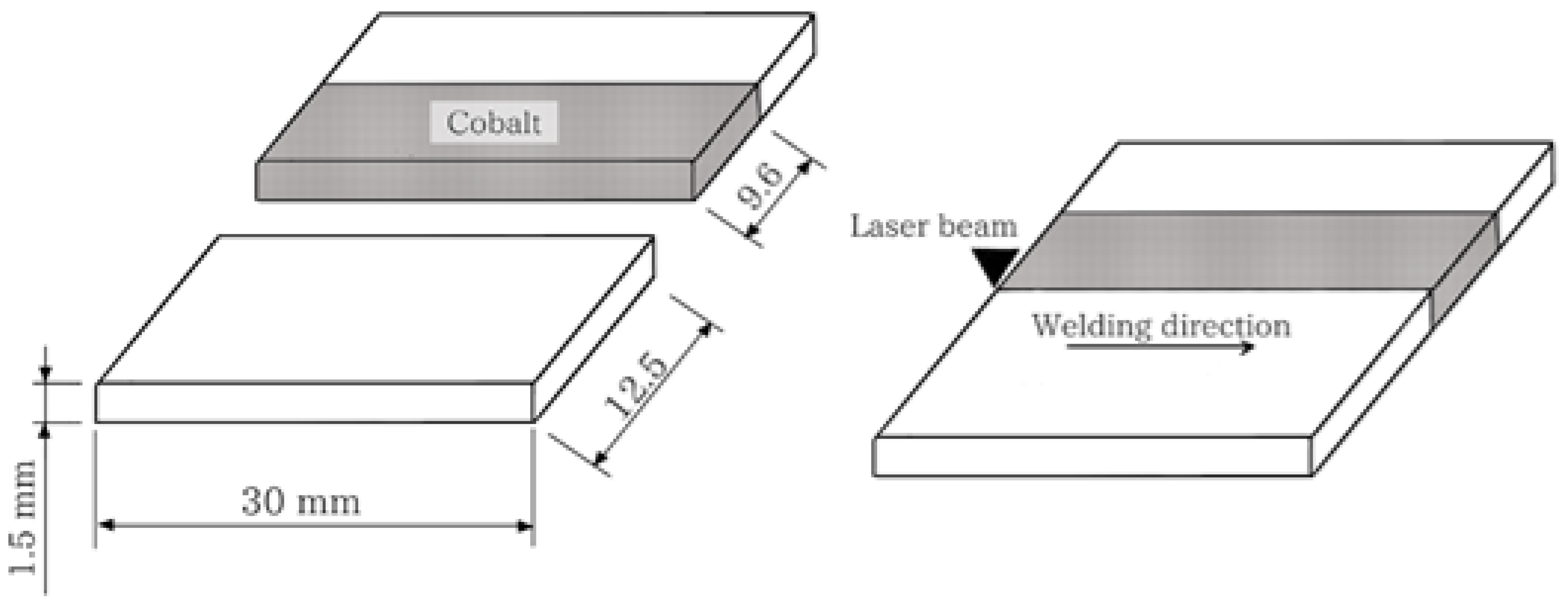
A Nd:YAG pulsed laser facility model UW-150 A (United Winners), with a 150 W maximum power and beam spot diameter 0.2 mm was employed. The weld that achieves a regular surface, without porosity, and with a deep weld pool greater than 50% of the sheet thickness was analyzed to determine the welding parameters. The samples were welded in pairs, with just one of the parts being coated with the electrodeposited layer of cobalt as presented in Figure 1.
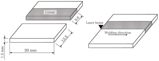
Figure 1.
Samples dimensions and schematic representation of the butt weld joint configuration.
The conditions were rated in terms of cobalt coating deposition time, obtaining three layers of thickness. Table 2 lists the welding parameters and the resulting thickness of the electrodeposited layer for each condition.
Table 2.
Cobalt electrodeposited layers and welding parameters.
For the metallographic analysis, the samples were sliced transverse to the weld direction after the welding operation. Using a silicone mold, the samples were set into cold-curing transparent epoxy resin. The samples were hand sanded, with each sanding change rotating the samples by 90 degrees. Alumina suspension was employed for polishing. The microstructure was revealed using Beraha’s reagent and then the samples were observed with scanning electron microscope (SEM) (Carl Zeiss EVO LS15). The austenite and ferrite volume fractions were calculated using the free image software Image J. For each condition, three samples were prepared. Ten SEM images (fusion zone) of each sample were examined. The micrographs were binarized, with ferrite appearing dark and austenite appearing light. The austenite/ferrite ratio was obtained by comparing the areas in the micrograph related to austenite and ferrite.
Vickers microhardness was evaluated perpendicular to the welding direction across the entire width of the weldments, with a test load of 10 gf for 10 s and intervals of 0.08 mm respecting the ASTM-E384 standard. Energy-dispersive X-ray spectroscopy (EDS) analyses were performed to determinate the amount (wt. %) of cobalt on the electrodeposited layers and in the fusion zone.
3. Results and Discussion
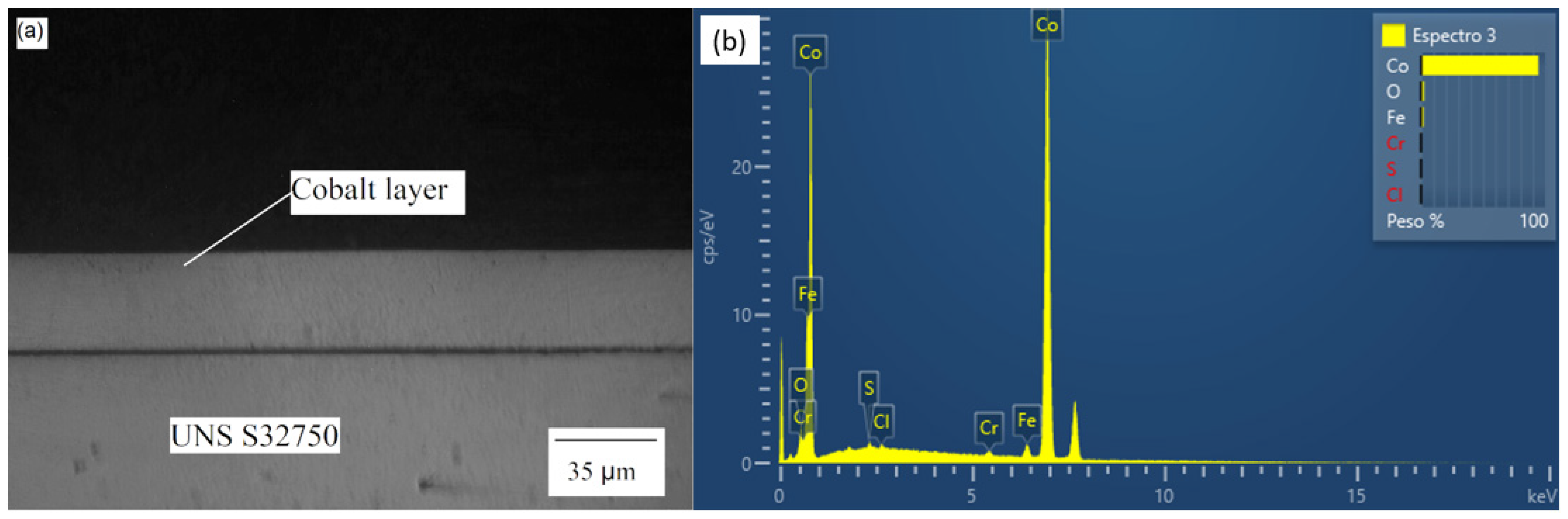
The optical micrograph and EDS diagram for the sample Co35 are presented in Figure 2. The other two samples (Co12 and Co20) had the same behavior. The composition of the electrodeposited layer was approximately 95% Co; the remaining 5% of Fe and Cr were probably from the base metal. The layer showed constant thickness, adhered well to the surface of the base metal, and was not affected by relevant present porosity. These characteristics contribute to a weld bead without discontinuities and achieves a uniform austenite/ferrite proportion distribution [29,33].
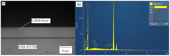
Figure 2.
Co35 (a) Optical micrograph and (b) EDS diagram.
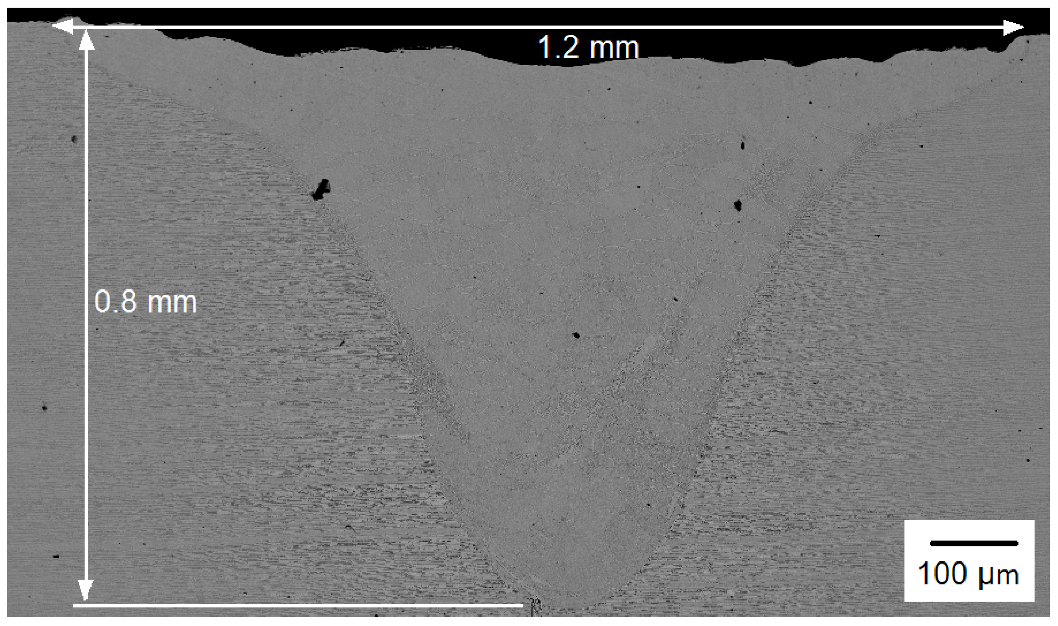
The SEM micrographs of the entire weld bead, which includes the base metal and the cross section of the weldment for the Co12 sample are shown in Figure 3 in order to display the weld bead geometry and dimensions. Because they all (Co20 and Co35) had the same geometry, only the weld bead for the Co12 condition is shown. It is the parameters and the welding mode that determine the geometry of the bead, and for all conditions, these variables were kept constant.
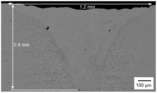
Figure 3.
SEM micrograph of the entire weld bead.
The weld bead had typical keyhole mode welding geometry: it was narrow and deep. The width and depth of the weld bead were 1.2 mm and 0.8 mm, respectively. As mentioned in the methodology, the welding parameters were selected to give a regular surface without porosity and a deep weld pool higher than 50% of the sheet thickness. The depth reached (0.8 mm) was greater than half of the total thickness of the base metal sheet (1.5 mm).
In general, the weld bead showed a very uniform microstructure along the fusion zone, indicating that there was efficient mixing of cobalt in the welding pool. The HAZ was relatively narrow, which was to be expected for laser welding [29]. It is possible to observe the balanced microstructure of the base metal, with the ferrite and austenite grains aligned in the rolling direction.
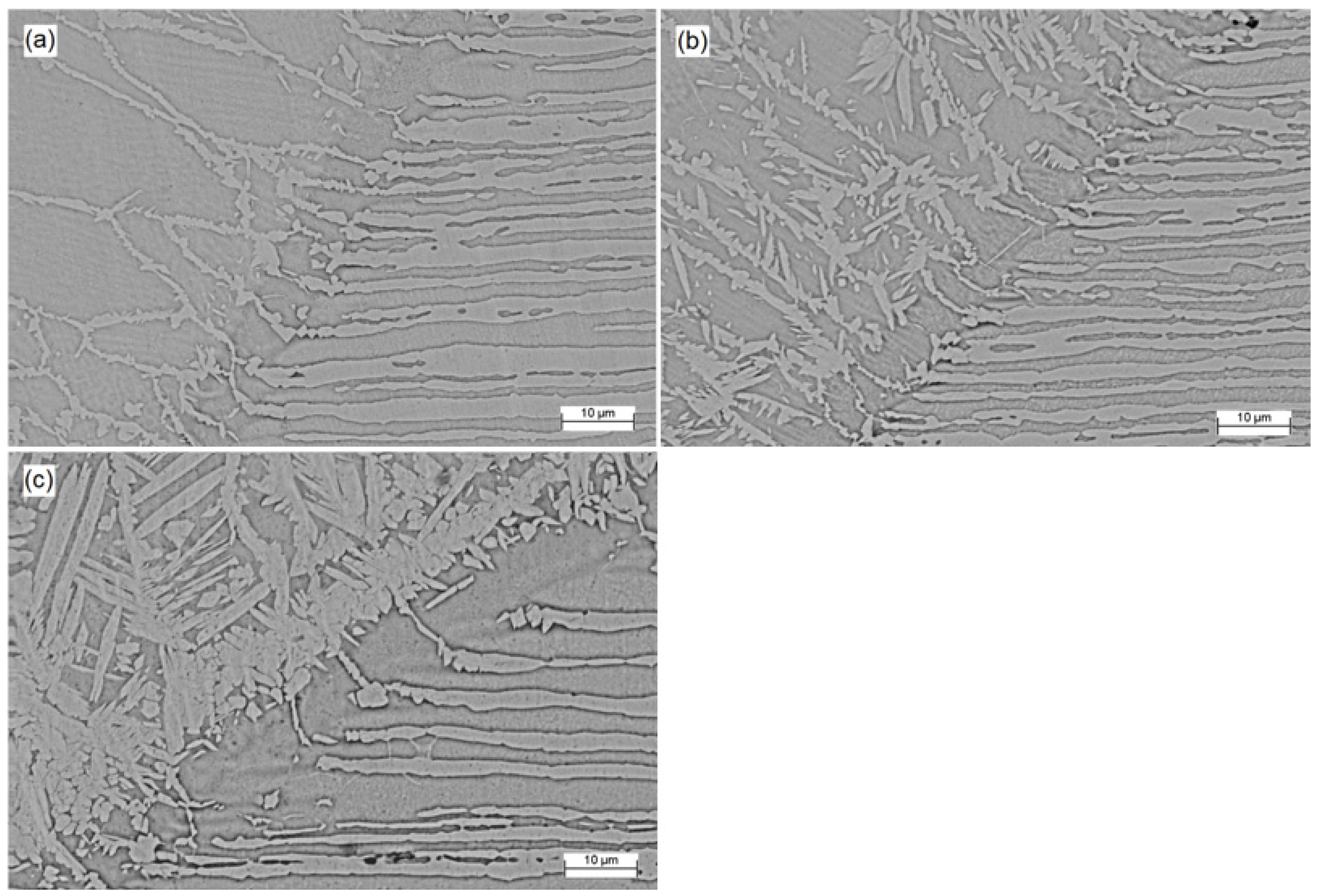
Figure 4 displays the SEM micrographs of the fusion zone for the Co12, Co20, and Co35 samples (a, b, and c, respectively). Austenite appears as the lightest phase and ferrite as the darkest. Thicker electrodeposited layers lead to an increase in cobalt concentration, which altered the morphology of austenite and increased its volume fraction. The sample Co12 had an unbalanced microstructure with several polygonal ferrite grains and allotriomorphic austenite at the boundaries. In SDSS welding, austenite is formed from a diffusional solid-state transformation so that, under high cooling rates as is usual for pulsed laser welding, the austenite formation cannot fully develop [6,33]. The effect of cobalt, as an austenite former, was not sufficient to overlap the thermal cycle effects imposed by laser welding.
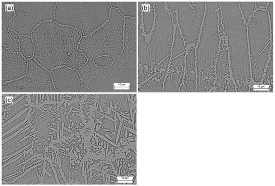
Figure 4.
Microstructure of fusion zone (SEM micrographs) for (a) Co12, (b) Co20 and (c) Co35.
Three different types of austenite can occur in SDSS weld metals: allotriomorphs, formed at the ferrite grain boundaries; Widmanstätten side plates that develop into the grain from the allotriomorph grain boundaries; and intragranular austenite [15]. The effect of the cobalt, deriving from the coating, in the morphology of austenite in the samples Co20 and Co35 can be observed, with the formation of Widmanstätten austenite nucleated from allotriomorph grain boundary austenite and intragranular austenite. The cobalt not only modified the morphology of austenite, but also increased its volume fraction, resulting in an approximately balanced microstructure for the sample Co35.
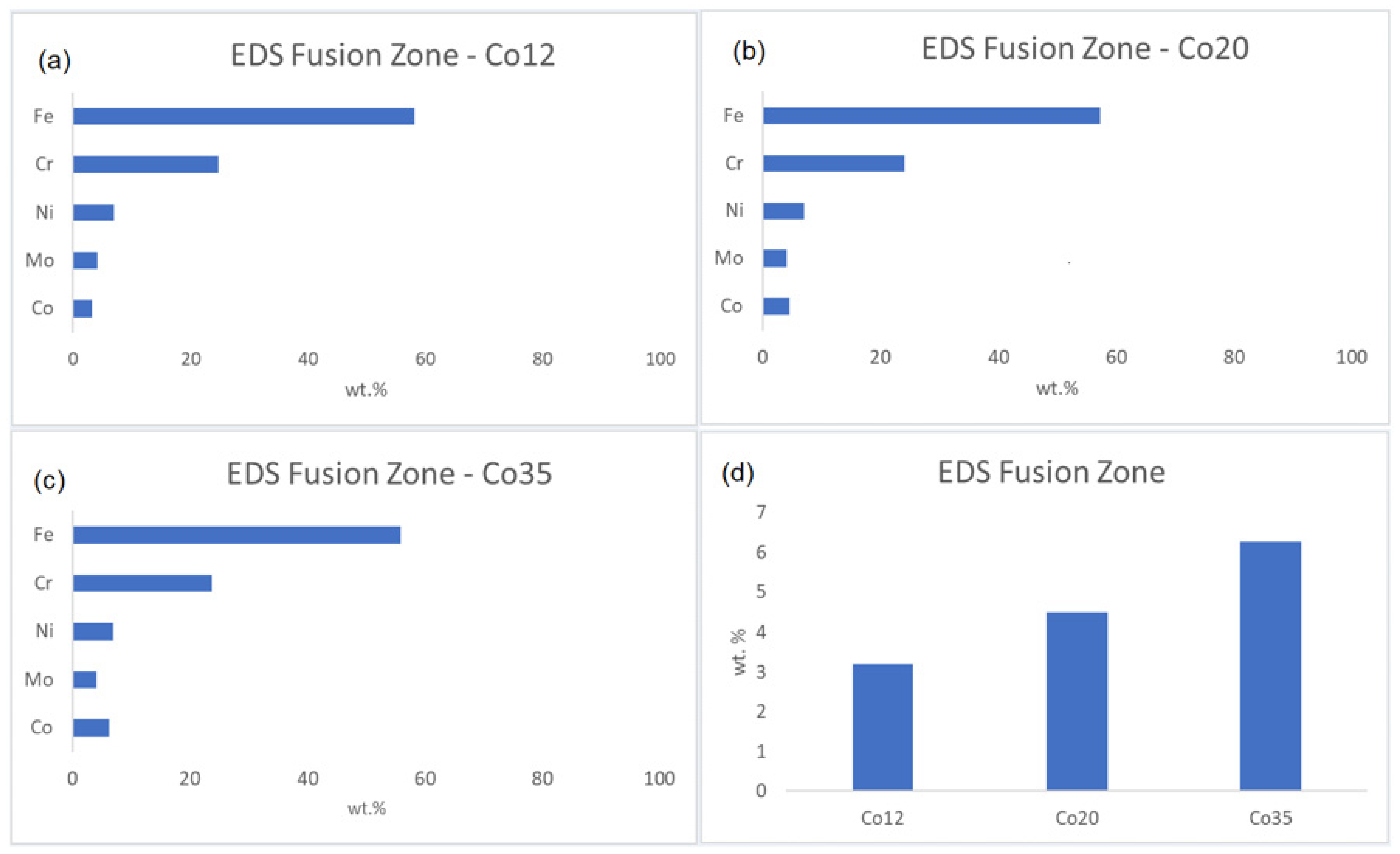
The cobalt enrichment, promoted by the electroplating technique, is estimated in Figure 5, which shows the composition (wt.%) of the fusion zone obtained by EDS analysis for the samples Co12, Co20, and Co35 (a, b, and c, respectively). The values shown are the average amounts (wt.%) of Fe, Cr, Ni, Mo, and Co in the melting zone. The Cr, Ni, Fe, and Mo concentrations remained the same of the base metal (Table 1). The cobalt amounts in the fusion zones were from the cobalt coating since the base metal does not have cobalt in its composition. Figure 5d presents the increase in cobalt amounts in the fusion zones for all the samples. The increase in cobalt amount increased the volume fraction of austenite, corroborating the results observed in the micrographs and proving the efficiency of the cobalt as austenite former [20,21,23].
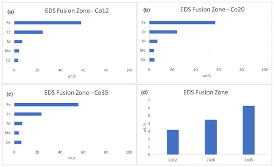
Figure 5.
Fusion zone composition for (a) Co12, (b) Co20, (c) Co35 and (d) Co wt.% increase for all the conditions.
Figure 6 displays the SEM micrographs of the transition between the base metal and fusion zone for each sample. Austenite appears as the lightest phase and ferrite as the darkest.
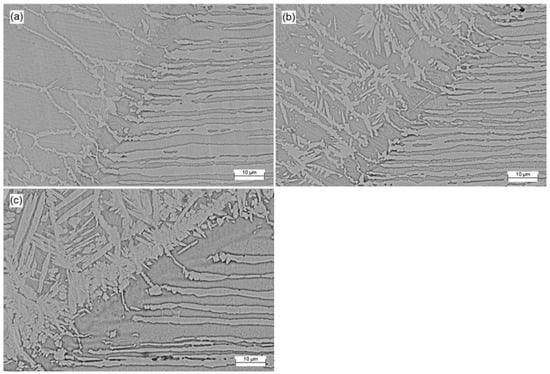
Figure 6.
SEM micrographs of transitions for (a) Co12, (b) Co20 and (c) Co35.
All weldments in the heat-affected zone (HAZ) have a phase balance of austenite/ferrite that is quite unbalanced, with ferrite taking up the highest volume fraction [16]. The austenite proportion at the HAZ is significantly shorter than at the weld center, even for Co35 sample, which displayed a balanced microstructure in the fusion zone. This is because the cooling rate has increased in this area without enough time for more austenite formation. The HAZ’s corrosion resistance is significantly impacted by the ferrite preponderance, which also increases the risk of pitting corrosion [29,34].
Table 3 presents the average volume fraction of ferrite and austenite in the fusion zone for each sample. The addition of cobalt, using the electroplating technique, was effective to balance the microstructure once austenite and ferrite were present in almost equal volume fraction in the Co35 sample. When all other welding conditions were kept constant throughout all the tests, this impact was a result of the cobalt coating. According to the literature, the weld bead must have a minimum austenite ratio of 25 to 30 percent for most industrial uses [6,7,8,9]. Considering these references, Co35 sample presents a good austenite volume fraction result.
Table 3.
Volume fractions for all the conditions.
Table 4 displays the average microhardness of the weld bead for each condition. The base metal average microhardness was 307 ± 4 HV. The Co12 sample presents the highest hardness due the predominantly ferritic microstructure. Higher ferrite content leads to high strength [35]. As envisaged, a drop in hardness is shown as the amount of austenite in the weld bead increases. Despite that the austenite/ferrite ration for the Co35 sample is nearly identical to that of the base material, the microhardness is slightly higher. The hardness increase is a consequence of the intergranular austenite development associated with a rapid cooling that introduce a strain hardening effect in microstructure, and also an effect from the higher overall extension of boundaries within single ferritic grains [19,29,36].
Table 4.
Weld bead hardness.
While a high ferrite content boosts mechanical strength at the expense of corrosion resistance, a high austenite content boosts corrosion resistance while lowering mechanical strength. Balanced austenite/ferrite proportions are essential for a desirable combination of mechanical strength and corrosion resistance [33,37], like sample Co35.
4. Conclusions
- It is feasible to use cobalt as an austenite-promoting element in SDSS welding. Once the volume fraction and morphology of austenite were changed, cobalt addition influenced its formation. An increase can be observed in the austenite proportion in the weld bead.
- The use of the cobalt electroplating technique was effective to promote austenite formation and, consequently, correct the resulting microstructure in SDSS laser welding. Given the difficulty of using alloying elements in Nd:YAG pulsed laser welding, the technique presented may expand the use of this welding in SDSS, ensuring proper phase balance in the weld bead.
- A higher austenite volume fraction in the fusion zone was obtained by thicker electrodeposited cobalt layers. The ideal scenario was using a cobalt coating that was 35 μm thick. The phase balance was confirmed by the austenite volume percentage of Ni35, which was close to 48 percent.
- The increase in austenite proportion caused a decrease in the microhardness of the weld bead. The microhardness dropped from about 375 HV (Co12) to 345 HV (Co35) as the cobalt layer’s thickness rose, being similar to that of the base metal. Although the volume fraction of austenite in the Co35 sample was close to that of the base metal, the hardness was approximately 15% higher because intragranular austenite formed as a result of the rapid cooling rates during the laser welding, and also showed an effect from the higher overall extension of boundaries within single ferritic grains.
- The results from the method outlined improves the application of Nd:YAG pulsed laser welding on DSS and might be used to broaden the design of the welding settings to include other DSS and laser sources.
Author Contributions
Conceptualization, E.J.D.C.J., B.B.S. and V.A.V.; methodology, E.J.D.C.J., B.B.S. and A.G.S.; validation, A.Z. and V.A.V.; formal analysis, F.M.F.A.V. and C.G.; writing—original draft preparation, E.J.D.C.J., B.B.S., F.M.F.A.V., C.G. and A.G.S.; writing—review and editing, I.C.; supervision, I.C., A.Z. and V.A.V. All authors have read and agreed to the published version of the manuscript.
Funding
This research received no external funding.
Conflicts of Interest
The authors declare no conflict of interest.
References
- Köse, C.; Topal, C. Texture. Microstructure and mechanical properties of laser beam welded AISI 2507 super duplex stainless steel. Mater. Chem. Phys. 2022, 289, 126490. [Google Scholar] [CrossRef]
- Pettersson, N.; Pettersson, R.F.A.; Wessman, S. Precipitation of Chromium Nitrides in the Super Duplex Stainless Steel 2507, Metall. Mater. Trans. A Phys. Metall. Mater. Sci. 2015, 46, 1062–1072. [Google Scholar] [CrossRef]
- Tan, H.; Jiang, Y.; Deng, B.; Sun, T.; Xu, J.; Li, J. Effect of Annealing Temperature on the Pitting Corrosion Resistance of Super Duplex Stainless Steel UNS S32750. Mater. Charact. 2009, 60, 1049–1054. [Google Scholar] [CrossRef]
- Khan, W.N.; Mahajan, S.; Chhibber, R. Investigations on Reformed Austenite in the Microstructure of Dissimilar Super Duplex/Pipeline Steel Weld. Mater. Lett. 2021, 285, 129109. [Google Scholar] [CrossRef]
- Nithin Raj, P.; Sivan, A.P.; Sekar, K.; Joseph, M.A. Effect of Austenite Reformation on Localized Corrosion Resistance of Hyper-Duplex Stainless Steel in Hot Chloride Solution. Int. J. Met. 2020, 14, 167–178. [Google Scholar] [CrossRef]
- Saravanan, S.; Raghukandan, K.; Sivagurumanikandan, N. Pulsed Nd: YAG Laser Welding and Subsequent Post-Weld Heat Treatment on Super Duplex Stainless Steel. J. Manuf. Process. 2017, 25, 284–289. [Google Scholar] [CrossRef]
- Ramkumar, K.D.; Thiruvengatam, G.; Sudharsan, S.P.; Mishra, D.; Arivazhagan, N.; Sridhar, R. Characterization of Weld Strength and Impact Toughness in the Multi-Pass Welding of Super-Duplex Stainless Steel UNS 32750. Mater. Des. 2014, 60, 125–135. [Google Scholar] [CrossRef]
- M-CR-601; Common Requirements Welding and Inspection of Piping. Norsok Standard, Standards Norway: Oslo, Norway, 2004; pp. 1–13.
- Kang, D.H.; Lee, H.W. Study of the Correlation between Pitting Corrosion and the Component Ratio of the Dual Phase in Duplex Stainless Steel Welds. Corros. Sci. 2013, 74, 396–407. [Google Scholar] [CrossRef]
- Vinoth Jebaraj, A.; Ajaykumar, L.; Deepak, C.R.; Aditya, K.V.V. Weldability, Machinability and Surfacing of Commercial Duplex Stainless Steel AISI2205 for Marine Applications—A Recent Review. J. Adv. Res. 2017, 8, 183–199. [Google Scholar] [CrossRef]
- Pezzato, L.; Lago, M.; Brunelli, K.; Breda, M.; Calliari, I. Effect of the Heat Treatment on the Corrosion Resistance of Duplex Stainless Steels. J. Mater. Eng. Perform. 2018, 27, 3859–3868. [Google Scholar] [CrossRef]
- Lin, P.-C.; Tsai, Y.-T.; Gan, N.-H.; Yang, J.-R.; Wang, S.-H.; Chang, H.-Y.; Lin, T.-R.; Chiu, P.-K. Characteristics of Flakes Stacked Cr2N with Many Domains in Super Duplex Stainless Steel. Crystals 2020, 10, 965. [Google Scholar] [CrossRef]
- Varbai, B.; Pickle, T.; Májlinger, K. Effect of heat input and role of nitrogen on the phase evolution of 2205 duplex stainless steel weldment. Int. J. Press. Vessel. Pip. 2019, 176, 103952. [Google Scholar] [CrossRef]
- Muthupandi, V.; Bala Srinivasan, P.; Shankar, V.; Seshadri, S.K.; Sundaresan, S. Effect of Nickel and Nitrogen Addition on the Microstructure and Mechanical Properties of Power Beam Processed Duplex Stainless Steel (UNS 31803) Weld Metals. Mater. Lett. 2005, 59, 2305–2309. [Google Scholar] [CrossRef]
- Muthupandi, V.; Bala Srinivasan, P.; Seshadri, S.K.; Sundaresan, S. Effect of Weld Metal Chemistry and Heat Input on the Structure and Properties of Duplex Stainless Steel Welds. Mater. Sci. Eng. A 2003, 358, 9–16. [Google Scholar] [CrossRef]
- Zhang, Z.; Jing, H.; Xu, L.; Han, Y.; Zhao, L.; Zhou, C. Effects of Nitrogen in Shielding Gas on Microstructure Evolution and Localized Corrosion Behavior of Duplex Stainless Steel Welding Joint. Appl. Surf. Sci. 2017, 404, 110–128. [Google Scholar] [CrossRef]
- Migiakis, K.; Papadimitriou, G.D. Effect of Nitrogen and Nickel on the Microstructure and Mechanical Properties of Plasma Welded UNS S32760 Super-Duplex Stainless Steels. J. Mater. Sci. 2009, 44, 6372–6383. [Google Scholar] [CrossRef]
- Pilhagen, J.; Sandström, R. Influence of Nickel on the Toughness of Lean Duplex Stainless Steel Welds. Mater. Sci. Eng. A 2014, 602, 49–57. [Google Scholar] [CrossRef]
- Tahaei, A.; Perez, A.F.M.; Merlin, M.; Valdes, F.A.R.; Garagnani, G.L. Effect of the Addition of Nickel Powder and Post Weld Heat Treatment on the Metallurgical and Mechanical Properties of the Welded UNS S32304 Duplex Stainless Steel. Soldag. Inspeção 2016, 21, 197–208. [Google Scholar] [CrossRef]
- Lippold, J.C.; Kotecki, D.J. Welding Metallurgy and Weldability of Stainless Steels; Wiley: Coshocton, OH, USA, 2005. [Google Scholar]
- Helis, L.; Toda, Y.; Hara, T.; Miyazaki, H.; Abe, F. Effect of Cobalt on the Microstructure of Tempered Martensitic 9Cr Steel for Ultra-Supercritical Power Plants. Mater. Sci. Eng. A 2009, 510–511, 88–94. [Google Scholar] [CrossRef]
- Davis, J.R. Nickel, Cobalt, and Their Alloys; ASM International: Almere, The Netherlands, 2000; 442p. [Google Scholar]
- Neville, A.; Hodgkiess, T. Comparative Study of Stainless Steel and Related Alloy Corrosion in Natural Sea Water. Br. Corros. J. 1998, 33, 111–120. [Google Scholar] [CrossRef]
- Uțu, I.-D.; Hulka, I.; Kazamer, N.; Constantin, A.T.; Mărginean, G. Hot-Corrosion and Particle Erosion Resistance of Co-Based Brazed Alloy Coatings. Crystals 2022, 12, 762. [Google Scholar] [CrossRef]
- Sivagurumanikandan, N.; Saravanan, S.; Sivakumar, G.; Raghukandan, K. Process Window for Nd:YAG Laser Welding of Super Duplex Stainless Steel. J. Russ. Laser Res. 2018, 39, 575–584. [Google Scholar] [CrossRef]
- Landowski, M. Influence of Parameters of Laser Beam Welding on Structure of 2205 Duplex Stainless Steel. Adv. Mater. Sci. 2019, 19, 21–31. [Google Scholar] [CrossRef]
- Silva Leite, C.G.; da Cruz Junior, E.J.; Lago, M.; Zambon, A.; Calliari, I.; Ventrella, V.A. Nd: YAG Pulsed Laser Dissimilarwelding of Uns S32750 Duplex with 316l Austenitic Stainless Steel. Materials 2019, 12, 2906. [Google Scholar] [CrossRef]
- Abdo, H.S.; Seikh, A.H.; Abdus Samad, U.; Fouly, A.; Mohammed, J.A. Electrochemical Corrosion Behavior of Laser Welded 2205 Duplex Stainless-Steel in Artificial Seawater Environment under Different Acidity and Alkalinity Conditions. Crystals 2021, 11, 1025. [Google Scholar] [CrossRef]
- Da Cruz Junior, E.J.; Gallego, J.; Settimi, A.G.; Gennari, C.; Zambon, A.; Ventrella, V.A. Influence of Nickel on the Microstructure, Mechanical Properties, and Corrosion Resistance of Laser-Welded Super-Duplex Stainless Steel. J. Mater. Eng. Perform. 2021, 30, 3024–3032. [Google Scholar] [CrossRef]
- Da Cruz Junior, E.J.; Seloto, B.B.; Ventrella, V.A.; Settimi, A.G.; Gennari, C.; Calliari, I.; Zambon, A. Addition of Nickel by the Watts Bath as a Way to Correct the Phase Balance on Nd:YAG Pulsed-Laser-Welded UNS S32750. Metall. Mater. Trans. A Phys. Metall. Mater. Sci. 2022, 53, 25–28. [Google Scholar] [CrossRef]
- Jiang, Y.; Tan, H.; Wang, Z.; Hong, J.; Jiang, L.; Li, J. Influence of Creq/Nieq on pitting corrosion resistance and mechanical properties of UNS S32304 duplex stainless steel welded joints. Corros. Sci. 2013, 70, 252–259. [Google Scholar] [CrossRef]
- Panda, H. Handbook on Electroplating with Manufacture of Electrochemicals; Asis Pacific Business Press Inc.: New Delhi, India, 2008; pp. 55–86. [Google Scholar]
- Mohammed, G.R.; Ishak, M.; Aqida, S.N.; Abdulhadi, H.A. Effects of Heat Input on Microstructure, Corrosion and Mechanical Characteristics of Welded Austenitic and Duplex Stainless Steels: A Review. Metals 2017, 7, 39. [Google Scholar] [CrossRef]
- Videira, A.M.; Mendes, W.R.; Ventrella, V.A.; Calliari, I. Increasing the Corrosion Resistance in the UNS S32750 Super Duplex Steel Welded Joints through Hybrid GTAW-Laser Welding and Nitrogen. Materials 2023, 16, 543. [Google Scholar] [CrossRef]
- Tan, H.; Wang, Z.; Jiang, Y.; Yang, Y.; Deng, B.; Song, H.; Li, J. Influence of Welding Thermal Cycles on Microstructure and Pitting Corrosion Resistance of 2304 Duplex Stainless Steels. Corros. Sci. 2012, 55, 368–377. [Google Scholar] [CrossRef]
- Haghdadi, N.; Cizek, P.; Hodgson, P.; Beladi, H. Microstructure dependence of impact toughness in duplex stainless steels. Mater. Sci. Eng. A 2019, 745, 369–378. [Google Scholar] [CrossRef]
- Ferreira, P.M.; Pereira, E.C.; Pinheiro, F.W.; Monteiro, S.N.; Azevedo, A.R.G. Effect of Solution Heat Treatment by Induction on UNS S31803 Duplex Stainless Steel Joints Welded with the Autogenous TIG Process. Metals 2022, 12, 1450. [Google Scholar] [CrossRef]

Disclaimer/Publisher’s Note: The statements, opinions and data contained in all publications are solely those of the individual author(s) and contributor(s) and not of MDPI and/or the editor(s). MDPI and/or the editor(s) disclaim responsibility for any injury to people or property resulting from any ideas, methods, instructions or products referred to in the content. |
© 2023 by the authors. Licensee MDPI, Basel, Switzerland. This article is an open access article distributed under the terms and conditions of the Creative Commons Attribution (CC BY) license (https://creativecommons.org/licenses/by/4.0/).