Abstract
The addition of high-content alloying elements and the unbefitting process make carbide-free bainite steel difficult in industrial production. Thus, we adopted a dynamic continuous cooling process for developing the high-strength cold-rolled low-alloy carbide-free bainitic steels in this study. The influence of cooling rates on the microstructure and mechanical properties was investigated by dilatometry, scanning electron microscopy (SEM), X-ray diffraction (XRD), electron backscatter diffraction (EBSD), and tensile tests. The results show that the bainitic ferrite plates were refined by decreasing the cooling rate, and more austenite was retained in the steel with a medium cooling rate. Both the TRIP effect and the refined bainitic ferrite plate contribute to the good strength–ductility match. Consequently, the propitious microstructure adjustment is critical for developing 980 MPa carbide-free bainitic steel.
1. Introduction
Carbide-free nano-bainitic steel, proposed by Bhadeshia and colleagues [1,2,3,4,5], has received a great deal of attention due to its excellent mechanical properties. This steel, containing about 1.0 wt.% carbon and 1.5 wt.% silicon, exhibits an ultra-high strength due to the nanoscale structure of bainitic ferrite and retention of austenite obtained by a lengthy period of austempering (even several days) [6,7,8,9]. However, strength is not the only unique parameter required, as ductility is also of vital importance for many structural applications. In addition, higher carbon content can induce poor weldability. [10]. Both the long bainitic transformation time and poor weldability are undesirable for industrial production. Therefore, many efforts have been devoted to improving the industrial applicability of carbide-free bainitic steels.
One of the attempts is the alloying design of carbide-free bainitic steel. Caballero et al. [11,12,13,14] designed a carbide-free bainitic steel by lowering the carbon content and increasing the nickel content, which increased the tensile strength by 1500–1600 MPa and the elongation by 10–15%. Al and/or Co was added to enhance the chemical driving force for the bainitic transformation, thus shortening the austempering time [5,15]. However, the high cost associated with the addition of the alloy elements is unsatisfactory. Some studies focus on the adjustment of the heat treatment process [16,17]. Ohtsuka [18] attempted to apply a strong magnetic field to shorten the bainitic transformation time. Nash et al. [19] took advantage of cyclic heat treatment to accelerate the bainitic transformation. Fast quenching, in order to obtain prior martensite after austenitizing, is also recognized as an effective method [20,21]; two or multiple stages of austempering were also adopted in previous studies [22,23,24,25]. Ostash et al. [26] found that the exposure time affects the cooling rate during heat treatment. These complex processes also induce difficulties in the production of carbide-free steels.
In this work, a low-alloy carbide-free bainitic steel was designed with consideration of the manufacturing cost and industrial line. We adopted a continuous cooling process to achieve bainitic transformation. Furthermore, the effect of the cooling rate on the microstructure evolution and the mechanical properties of the carbide-free bainitic steels was analyzed. Scanning electron microscopy (SEM), electron backscattered diffraction (EBSD), and X-ray diffraction (XRD) techniques were conducted to characterize the microstructure and to explore the relationship between the microstructure and mechanical properties.
2. Materials and Methods
The chemical composition of the steel in this study is presented in Table 1. It was prepared by vacuum induction melting and then reheated to 1200 °C for forging. The billet was homogenized at 1200 °C, followed by hot rolling to a 5 mm thickness. The hot-rolled sheet was then cold rolled down to a 1.6 mm thickness after the acid-pickling process. Cuboid samples 10 × 1.5 × 1 mm3 in size were cut from the cool-rolled sheets by wire cutting, and they were adopted for the measurement of the martensite transformation starting (Ms) temperature after full austenitization using a high-resolution DIL 805A/D dilatometer (Bärh, Hüllhorst, Germany). The continuous cooling process for bainitic transformation was designed according to the measured Ms temperature, which allows the transformation to proceed gradually. The heat treatment process, revealed in Figure 1, was performed on both cuboid samples using a dilatometer and cool-rolled sheets using furnaces. The heat treatment processes include fast cooling to 420 °C after austenitization at 920°C for 10 min, and then slowly cooling down to 360 °C at three cooling rates of 2 °C·min−1 (bainitic transformation for 30 min), 1 °C·min−1 (bainitic transformation for 60 min) and 0.5 °C·min−1 (bainitic transformation for 120 min), followed by water quenching (fast cooling) to ambient temperature. Three samples treated by the processes described above are labeled as BS30, BS60, and BS120, respectively.

Table 1.
Chemical composition of the studied steel (wt.%).
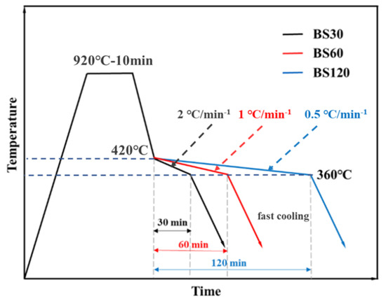
Figure 1.
The applied heat treatment processes applied in this study.
The samples for the SEM (Zeiss Gimini300, Oberkochen, Germany) observation were prepared by mechanical grinding and polishing before being etched in a 4% nital solution (Tiangang Chemical, Shenyang, China). The EBSD measurements were conducted on the undeformed and deformed samples, which were prepared by electropolishing (Buehler Electromet 4, Shenyang, China) at room temperature in a 12.5% perchloric acid alcohol solution (Tiangang Chemical, Shenyang, China) at an operating voltage of 25 V after mechanical grinding. The EBSD scans were performed on an OXFORD system, attached to a Zeiss Gimini300 (Oberkochen, Germany), at an accelerated voltage of 20 kV, a step size of 0.07 μm, and a specimen tilt of 70°. The EBSD data acquisition and subsequent processing were performed using the CHANNEL5 software (Version sp11b, Oxford Instrument, Oxford, UK). According to the procedure described in [27], the volume fraction of martensite was calculated by analyzing the band slope (BS) figure by EBSD. The volume fraction of blocky retained austenite was also measured by EBSD. The bainitic ferrite plate and the orientation between bainite and austenite are shown in inverse pole figure (IPF) maps (IPF is plotted in the normal direction (ND)). Concurrently, the orientation relationship between bainitic ferrite and parent austenite was measured by pole figures of EBSD [28]. The thickness of the bainitic ferrite plate, t, was measured according to the procedure described in the previous study [29]. The thickness t was determined by equation t = 2 Lα/π, in which the mean linear intercept (Lα) was measured by the linear intercepts on the SEM micrographs. XRD samples 10 × 8 × 1.6 mm3 in size were electropolished using the same schedule as the EBSD samples and analyzed by a SmartLab9KW (Rigaku, Tokyo, Japan) quantitative XRD using Cu Kα radiation. Diffraction of 2θ, from 30° to 110°, with a step of 0.01° was used. Two regions were measured for each sample. The volume fraction and the average carbon content of retained austenite at room temperature were calculated according to the XRD results. Diffraction-integrated intensities of (200)α, (211)α, (200)γ, (220)γ, and (311)γ were used, and the volume fraction of retained austenite was estimated by the following Formula (1) [30]:
where Vγ, Iα, and Iγ are the volume fraction of retained austenite and the average integral intensities of the ferrite and austenite peaks, respectively. The carbon content of retained austenite can be determined by the following Equation (2) [31]:
where αγ, xC, xMn, and xAl are the austenitic lattice constant and the mass fractions of carbon, manganese, and aluminum in wt.%, respectively.
Vγ = 1.4 Iγ/(1.4 Iγ + Iα)
αγ = 3.556 + 0.0453xC + 0.00095xMn + 0.0056xAl
Tensile specimens with a gauge length of 25 mm were machined from the heat treatment sheet parallel to the rolling direction. Tensile tests were performed according to the standard ASTM E8-04 on the AI-7000 LA20 tensile equipment (Shenyang, China) at a speed of 2 mm·min−1. Three tensile samples were tested for each condition.
3. Results
3.1. Effect of the Cooling Rate on the Microstructure Evolution
The SEM micrographs revealed that the microstructures of the three samples are similar, consisting of allotriomorphic ferrite, bainitic ferrite, film-like retained austenite, and blocky retained austenite (M/A) (Figure 2). A full austenite microstructure could be obtained after isothermal holding at 920 °C for 10 min (Figure 1), according to the dilatometric curve. During the subsequent cooling process to 420 °C, a small amount of allotriomorphic ferrite was obtained by austenite transformation due to the inadequate cooling rate of the cold-rolled sheets. Then, bainitic transformation proceeded during the slow cooling process from 420 °C to 360 °C. As the Ms temperature was measured to be 380 °C, the initial temperature of the slow cooling should be at the temperature region of bainitic transformation. This is also clearly revealed by the dilatation curve, as a significant expansion occurred during the slow cooling process (Figure 3a). The bainitic ferrite between the austenite plates was obtained, and the carbon was partitioned into the surrounding austenite plates from the formed bainitic ferrite. During the subsequent cooling process to ambient temperature, residual austenite partially transformed into martensite (Figure 3b).

Figure 2.
SEM micrographs of the three samples with different cooling rates. (a) BS30; (b) BS60; (c) BS120. Note that AF, M/A, BF, and FRA are allotriomorphic ferrite, blocky retained austenite, bainitic ferrite, and film-like retained austenite, respectively.
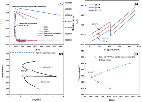
Figure 3.
(a) The curves of the relative change of length and the dilation rate as a function of time during the slow cooling process; (b) the relative change of length as a function of temperature during the process of cooling to ambient temperature; (c) TTT diagrams calculated by the MUCG83 thermodynamic model; (d) the time and temperature curve for 99.9% of the bainite transformation measured with a dilatometer.
Even though the three samples have similar microstructure constitutions, the fraction and morphology of the phases are diverse and are caused by the different cooling rates (Figure 1a and Figure 4a,d,g). It is well known that bainitic transformation occurs at a temperature below T0, when the free energy of bainitic ferrite becomes less than that of austenite at the same composition [11,32]. The time–temperature–transformation diagram (TTT) was studied with the MUCG83™ thermodynamic model, and 99.9% of the bainite transformation data was measured with a dilatometer. The T0 temperature of the studied steels was calculated to be 505 °C, and the nose temperature of the TTT curves was measured to be 430 °C (Figure 3c,d). Thus, a significant bainitic transformation occurred during the initial stage of the slow cooling stage (Figure 3a). The greatest bainitic transformation was observed in BS120 because of the longer period of time that the steel was held at a temperature near the nose temperature. This is verified by the relative length change during the bainitic transformation process. Therefore, less austenite was retained in sample BS120 than in the other two samples when the slow cooling ended. The sub-units of bainitic ferrite were formed at the austenite grain boundaries, and then new sub-units were nucleated at the previous tips in order to develop a sheaf structure [33]. The parallel bainitic ferrite plates are in a similar crystallographic orientation (Figure 4c,f,i), and the relative orientation between bainitic ferrite and parent austenite was close to a K-S relationship. Accompanying this procedure, the carbon partitioned from bainitic ferrite to the surrounding austenite [32]. With the cooling rate decreasing, there was more time for carbon diffusion, thus creating greater stability for the austenite. The thickness of the bainitic ferrite plate is determined by the driving force and the austenite stability [2,10]. The driving forces of bainitic transformation in the three samples were the same because of the equal temperature region, and the austenite in sample BS120 had the greatest stability during the slow cooling. Therefore, sample BS120 obtained the thinnest bainitic ferrite plate with a thickness of 0.26 ± 0.20 μm, while those of samples BS30 and BS60 were 0.48 ± 0.26 μm and 0.28 ± 0.18 μm, respectively (Figure 2). Consequently, the bainitic ferrite with the greatest amount of stable austenite and with the thinnest plate was obtained in sample BS120.
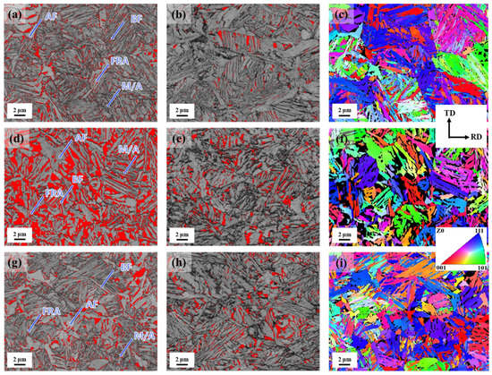
Figure 4.
EBSD micrographs of the three samples. The image quality (IQ) with red austenite phase maps before the deformation (a,d,g) and after the deformation (b,e,h), and the IPF maps (c,f,i) of sample BS30 (a–c), BS60 (d–f), and BS120 (g–i) showing bainitic ferrite (the black region is the FCC phase, Z0 direction is related to the ND).
Following the slow cooling process, a martensitic transformation occurred in three samples (Figure 3b). The film-like retained austenite between the bainitic ferrite plates was more enriched with carbon, thereby inducing greater chemical stability. Additionally, the fine size of the film-like retained austenite was beneficial for its mechanical stability. Both results showed that blocky austenite was more prone to transform into bainite, revealing its M/A microstructure at ambient temperature (Figure 2). The martensitic transformation starting (Ms’) temperatures are 201 °C, 187 °C, and 175 °C for samples BS30, BS60, and BS120, respectively (Figure 3b). The Ms’ temperature reduces with the slowly decreasing cooling rate, resulting from the enhanced austenite stability, as discussed above. The carbon content of retained austenite was measured by XRD to be 1.36 wt.%, 1.46 wt.%, and 1.68 wt.% for samples BS30, BS60, and BS120, respectively, which are nearly equal to the carbon contents of austenite after slowly cooling, due to the diffusionless martensitic transformation (Figure 5, Table 2). It also verified the enhanced austenite stability by a lower slow cooling rate.
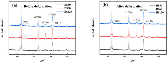
Figure 5.
XRD patterns of the three samples before (a) and after deformation (b).

Table 2.
Volume fraction and carbon content of retained austenite measured by XRD and EBSD, and the volume fraction of martensite of the undeformed samples measured by EBSD.
The EBSD micrographs present two morphologies of retained austenite, blocky retained austenite partially transformed into martensite and film-like retained austenite between the bainitic ferrite plates (Figure 4a,d,g). The fractions of retained austenite were measured by EBSD to be 9.4 vol.%, 21.0 vol.%, and 10.5 vol.% for samples BS30, BS60, and BS120, respectively, which are lower than the XRD results of 11.5 ± 0.78 vol.%, 27.8 ± 0.36 vol.%, and 12.9 ± 1.31 vol.% for samples BS30, BS60, and BS120, respectively (Table 2). This is due to the limited resolution of the EBSD measurement, which may be explained by the possibly undetected film-like retained austenite on account of its smaller size. In addition, a smaller amount of austenite was retained in samples BS30 and BS120 than in sample BS60. The smallest amount of austenite was retained in BS120 after the slow cooling process, and more austenite was transformed into martensite in sample BS30 (Figure 5, Table 2). The martensite fraction was calculated to be 15.9 vol.%, 10.5 vol.%, and 12.1 vol.% according to the EBSD results (Table 2)
3.2. The Relationship between the Microstructure and Mechanical Properties
The mechanical properties of the bainitic steels were measured by tensile tests, and the results are presented in Table 3. It shows the various mechanical properties of the three samples, despite the similar microstructure constitutions resulting from the different phase fractions. Sample BS30 exhibits the highest yield strength of 851 ± 3 MPa, whereas the yield strength of samples BS60 and BS120 are 754 ± 3 and 756 ± 4 MPa, respectively. The yield strength of the materials with the complex phase microstructure is determined by the mixture of each phase. The higher yield strength in sample BS30 is attributed to a higher fraction of hard martensite, which has strength as great as 1500 MPa (Figure 3b, Table 2) [34]. Otherwise, the BS60 sample contained the highest volume fraction of retained austenite. In this case, more stress relaxations may have occurred [26], resulting in the same increase in yield strength as in the BS120 sample. Although the other two samples have lower yield strengths, their tensile strength and elongation are greater than that of sample BS30, which is related to their work-hardening behavior.

Table 3.
Tensile properties of the three samples.
The true stress–strain curve and work-hardening-rate curve of the three samples are shown in Figure 6a. There was an arresting decrease in the work-hardening rate in the initial stage, which corresponded to the elasto-plastic transition. The work-hardening rates of the three samples all showed a monotonous decrease with the increasing strain. However, samples BS60 and BS120 have higher work-hardening rates when the strain is greater than 0.018. More austenite with a 27.8 ± 0.36 vol.% was retained in sample BS60, which transformed into the martensite during the deformation process. It could be observed that 74.5% of austenite was consumed by deformation, which is greater than 53.1% and 36.2% for samples BS30 and BS120 (Figure 5 and Figure 6b, Table 2). The volume fractions of blocky retained austenite of the BS30, BS60, and BS120 samples measured in the EBSD images, were 6.16%, 11.18%, and 7.36%, respectively. Therefore, the significant TRIP effect of austenite in sample BS60 contributed to the greater work-hardening rate, thus, the great tensile strength. Except for the TRIP effect, the dislocation slipping is also a critical factor for the work-hardening behavior. For sample BS120, it has the finest bainitic ferrite plate, which offers a small average free path for the dislocation glide. It is beneficial for the dislocation accumulation and is thus dedicated to the greater work-hardening capability. Consequently, the greater tensile strengths of 1087 ± 3 MPa for sample BS60 and 1087 ± 9 MPa for sample BS120 were achieved.
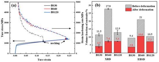
Figure 6.
True stress–strain curves and work-hardening rate curves for samples BS30, BS60, and BS120 (a), the volume fraction of austenite before and after deformation, measured by XRD and EBSD (b).
Additionally, samples BS60 and BS120 exhibited better tensile ductility (Table 3). The elongations of these two samples were 27.6 ± 0.3% and 27.8 ± 0.6%, respectively, which were greater than that of 12.9 ± 2.2% in sample BS30. The brittle fracture of hard martensite in the carbide-free bainitic steels generally provided nuclei for void growth [35]. Sample BS30 had the highest volume of martensite (Table 2). The larger amount of martensite in sample BS30 induced poor ductility, despite the contribution of the TRIP effect. Eventually, the product of strength and elongation (PSE) of samples BS60 and BS120 were comparable with the third-generation automotive steels (Figure 7) [33,34,36,37,38,39,40,41,42,43,44]. With regard to the considerations applicable to industrial production, the heat treatment of BS60 was optimal.
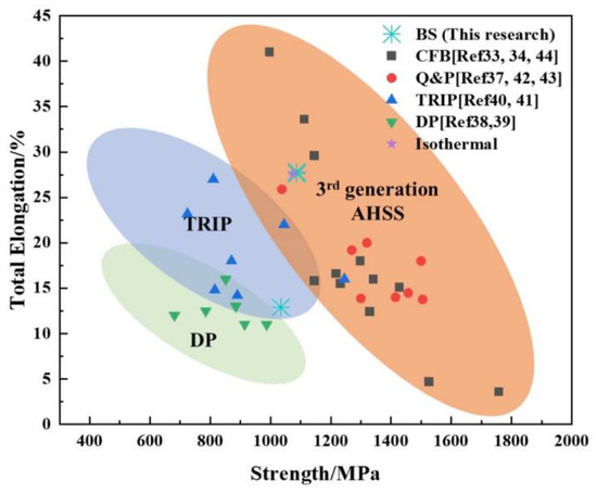
Figure 7.
Performances of the designed CFB steels, compared to TRIP, DP, and 3rd generation AHSS in [33,34,36,37,38,39,40,41,42,43,44] and the isothermal sample (holding at 400 °C for an hour).
4. Conclusions
In the present study, 980 MPa grade low-alloy carbide-free bainitic steels were developed by adopting a dynamic continuous cooling process for bainitic transformation. The effect of the cooling rate on the microstructure and the mechanical properties of the samples was investigated. The main conclusions are summarized as follows.
- (1)
- The microstructure of the studied carbide-free bainitic steels consists of allotriomorphic ferrite, bainitic ferrite, plate-retained austenite, and blocky retained austenite (M/A). With the cooling rate decreasing, the thickness of the bainitic ferrite plate was reduced, which was caused by the carbon diffusion, thus strengthening the austenite. The greatest amount of austenite of 27.8 ± 0.36 vol.% was retained in sample BS60, whereas sample BS30 had the greatest martensite fraction of 15.9 vol.%.
- (2)
- Sample BS30 has poor ductility due to the existence of a large fraction of martensite. With the significant TRIP effect in sample BS60 and the thinnest bainitic ferrite plate in sample BS120, a greater work-hardening capability was achieved in the two samples. Consequently, they exhibit a good strength–ductility match with the PSE, up to 30GPa·%.
Author Contributions
Conceptualization, P.C., D.Y. and H.Y.; methodology, D.Y. and P. Chen; experiment, P.W. and T.W.; formal analysis, P.W.; investigation, P.W., T.W. and P.C.; writing—original draft preparation, P.W.; writing—review and editing, P.W. and P.C.; All authors have read and agreed to the published version of the manuscript.
Funding
This research was funded by Fundamental Research Funds for the Central University (No. N2202007), National Natural Science Foundation (Nos. 52101128, 51804072), National Key R&D Program (No. 2018YFE0306102), Postdoctoral Science Foundation (No. 2022M710021) and Postdoctoral Research Fund of Northeastern University of China (No. 20220202).
Data Availability Statement
The data presented in this study are available on request from the corresponding author.
Acknowledgments
Special thanks are also due to the instrumental or data analysis from Analytical and Testing Center, Northeastern University, China.
Conflicts of Interest
The authors declare no conflict of interest.
References
- Bhadeshia, H.K.D.H.; Edmonds, D.V. Bainite in silicon steels: New composition-property approach Part1. Metal Sci. 1983, 17, 411–419. [Google Scholar] [CrossRef]
- Caballero, F.G.; Bhadeshia, H.K.D.H. Very strong bainite. Curr. Opin. Solid State Mater. Sci. 2004, 8, 251–257. [Google Scholar]
- Garcia-Mateo, C.; Caballero, F.G.; Bhadeshia, H.K.D.H. Mechanical Properties of Low-Temperature Bainite. Mater. Sci. Forum 2005, 500–501, 495–502. [Google Scholar]
- Hase, K.; Garcia-Mateo, C.; Bhadeshia, H.K.D.H. Bimodal size-distribution of bainite plates. Mater. Sci. Eng. A 2006, 438–440, 145–148. [Google Scholar]
- Bhadeshia, H.K.D.H. Nanostructured bainite. Proc. R. Soc. A 2010, 466, 3–18. [Google Scholar]
- Timokhina, I.B.; Beladi, H.; Xiong, X.Y.; Adachi, Y.; Hodgson, P.D. Nanoscale microstructural characterization of a nanobainitic steel. Acta Mater. 2011, 14, 5511–5522. [Google Scholar]
- Hu, F.; Hodgson, P.D.; Wu, K.M. Acceleration of the super bainite transformation through a coarse austenite grain size. Mater. Lett. 2014, 122, 240–243. [Google Scholar]
- Garcia-Mateo, C.; Caballero, F.G. Ultra high strength Bainitic Steels. ISIJ Int. 2003, 43, 1736–1740. [Google Scholar]
- Garcia-Mateo, C.; Caballero, F.G.; Bhadeshia, H.K.D.H. Acceleration of Low-temperature Bainite. ISIJ Int. 2003, 43, 1821–1825. [Google Scholar]
- Yang, H.S.; Bhadeshia, H.K.D.H. Designing low carbon, low temperature bainite. Mater. Sci. Technol. 2008, 24, 335–342. [Google Scholar]
- Caballero, F.G.; Santofimia, M.J.; Capdevila, C.; Garcia-Mateo, C.; Andres, C.G. Design of Advanced Bainitic Steels by Optimisation of TTT Diagrams and T0 Curves. ISIJ Int. 2006, 46, 1479–1488. [Google Scholar]
- Caballero, F.G.; Allain, S.; Cornide, J.; Puerta Velasquez, J.D.; Garcia-Mateo, C.; Miller, M.K. Design of cold rolled and continuous annealed carbide-free bainitic steels for automotive application. Mater. Des. 2013, 49, 667–680. [Google Scholar]
- Caballero, F.G.; Bhadeshia, H.K.D.H.; Mawella, K.J.A.; Jones, D.G.; Brown, P. Design of novel high strength bainitic steels: Part 1. Mater. Sci. Technol. 2001, 17, 512–516. [Google Scholar]
- Caballero, F.G.; Bhadeshia, H.K.D.H.; Mawella, K.J.A.; Jones, D.G.; Brown, P. Design of novel high strength bainitic steels: Part 2. Mater. Sci. Technol. 2001, 17, 517–522. [Google Scholar]
- Chen, S.; Wang, C.; Shan, L.; Zhao, X.; Xu, W. Effect of isothermal time and alloy elements on bainitic transformation below Ms in medium Mn Steels. IOP Conf. Ser. Mater. Sci. Eng. 2019, 592, 012018. [Google Scholar]
- Yang, Z.N.; Chu, C.H.; Jiang, F.; Qin, Y.M.; Long, X.Y.; Wang, S.L.; Chen, D.; Zhang, F.C. Accelerating nano-bainite transformation based on a new constructed microstructural predicting model. Mater. Sci. Eng. A 2019, 748, 16–20. [Google Scholar]
- Chen, X.; Wang, F.M.; Li, C.R.; Zhang, J. Dynamic continuous cooling transformation, microstructure and mechanical properties of medium-carbon carbide-free bainitic steel. High Temp. Mat. Process. 2020, 39, 304–316. [Google Scholar]
- Ohtsuka, H. Effects of a High Magnetic Field on Bainitic and Martensitic Transformations in Steels. Mater. Trans. 2007, 48, 2851–2854. [Google Scholar] [CrossRef]
- Sista, V.; Nash, P.; Sahay, S.S. Accelerated bainitic transformation during cyclic austempering. J. Mater. Sci. 2007, 42, 9112–9115. [Google Scholar]
- Toji, Y.; Matsuda, H.; Raabe, D. Effect of Si on the acceleration of bainite transformation by pre-existing martensite. Acta Mater. 2016, 116, 250–262. [Google Scholar]
- Santofimia, M.J.; van Bohemen, S.M.C.; Sietsma, J. Combining bainite and martensite in steel microstructures for light weight applications. J. S. Afr. Inst. Min. Metall. 2013, 113, 143–148. [Google Scholar]
- Zhuang, W.C.; Jiang, Y.M.; Zhou, W.T.; Liang, Z.Y.; Northwood, D.O.; Liu, C. Influence of Multi-Step Austempering Temperature on Tensile Performance of Unalloyed Ductile Iron. Key Eng. Mater. 2019, 803, 3–7. [Google Scholar]
- Avishan, B.; Tavakolian, M.; Yazdani, S. Two-step austempering of high performance steel with nanoscale microstructure. Mater. Sci. Eng. A 2017, 693, 178–185. [Google Scholar]
- Mousalou, H.; Yazdani, S.; Avishan, B.; Ahmadi, N.P.; Chabok, A.; Pei, Y.T. Microstructural and mechanical properties of low-carbon ultra-fine bainitic steel produced by multi-step austempering process. Mater. Sci. Eng. A 2018, 734, 329–337. [Google Scholar]
- Gao, G.H.; Guo, H.R.; Gui, X.L.; Tan, Z.L.; Bai, B.Z. Inverted multi-step bainitic austempering process routes: Enhanced strength and ductility. Mater. Sci. Eng. A 2018, 736, 298–305. [Google Scholar]
- Ostash, O.P.; Kulyk, V.V.; Poznyakov, V.D.; Gaivorons’kyi, O.A.; Vira, V.V. Influence of the modes of heat treatment on the strength and cyclic crack-growth resistance of 65G steel. Mater. Sci. 2019, 54, 776–782. [Google Scholar]
- Lia, S.C.; Guo, C.Y.; Hao, L.L.; Kang, Y.L.; An, Y.G. In-situ EBSD study of deformation behaviour of 600 MPa grade dual phase steel during uniaxial tensile tests. Mater. Sci. Eng. A 2019, 795, 624–632. [Google Scholar]
- Wang, T.L.; Qian, L.H.; Yu, W.L.; Li, K.F.; Zhang, F.C.; Meng, J.Y. Effect of ferrite-austenite morphology and orientation relationship on bainite transformation in low-alloy TRIP steels. Mater. Charact. 2022, 184, 111656. [Google Scholar]
- Garcia-Mateo, C.; Jimenez, J.A.; Lopez-Ezquerra, B.; Rementeria, R.; Morales-Rivas, L.; Kuntz, M.; Caballero, F.G. Analyzing the scale of the bainitic ferrite plates by XRD, SEM and TEM. Mater Charact. 2016, 122, 83–89. [Google Scholar]
- Sugimoto, K.I.; Usui, N.; Kobayashi, M.; Hashimoto, S.I. Effects of volume fraction and stability of retained austenite on ductility of TRIP-aided dual-phase steels. ISIJ Int. 1992, 32, 1311–1318. [Google Scholar]
- Cheng, L.; Bottger, A.; de Keijser, T.H.; Mittemeijer, E.J. Lattice parameters of iron-carbon and iron-nitrogen martensites and austenites. Scr. Metall. Mater. 1990, 24, 509–514. [Google Scholar]
- Bhadeshia, H.K.D.H.; Edmonds, D.V. The mechanism of bainite formation in steels. Acta Mater. 1980, 28, 1265–1273. [Google Scholar]
- Zhou, M.; Xu, G.; Tian, J.; Hu, H.; Yuan, Q. Bainitic Transformation and Properties of Low Carbon Carbide-Free Bainitic Steels with Cr Addition. Metals 2017, 7, 263. [Google Scholar]
- Franceschi, M.; Miotti Bettanini, A.; Pezzato, L.; Dabalà, M.; Jacques, P.J. Effect of Multi-Step Austempering Treatment on the Microstructure and Mechanical Properties of a High Silicon Carbide-Free Bainitic Steel with Bimodal Bainite Distribution. Metals 2021, 11, 2055. [Google Scholar] [CrossRef]
- Jacques, P.J.; Furnémont, Q.; Pardoen, T.; Delannay, F. On the role of martensitic transformation on damage and cracking resistance in TRIP-assisted multiphase steels. Acta Mater. 2001, 49, 139–152. [Google Scholar]
- Fonstein, N. Advanced High Strength Sheet Steel; Springer International Publishing: Cham, Switzerland, 2015; pp. 12–13. [Google Scholar]
- Paravicini Bagliani, E.; Santofimia, M.J.; Zhao, L.; Sietsma, J.; Anelli, E. Microstructure, tensile and toughness properties after quenching and partitioning treatments of a medium-carbon steel. Mater. Sci. Eng. A 2013, 599, 486–495. [Google Scholar]
- Badkoobeh, F.; Mostaan, H.; Rafiei, M.; Bakhsheshi-Rad, H.R.; Berto, F. Microstructural Characteristics and Strengthening Mechanisms of Ferritic–Martensitic Dual-Phase Steels: A Review. Metal 2022, 12, 101. [Google Scholar]
- Liu, L.T.; Fu, B.; Guo, Y.H.; Wei, L.Q. Simultaneous Improvement of Strength and Ductility of Dual-Phase Steel Processed by Multi-Step Cyclic Rolling and Intercritical Annealing. Materials 2022, 15, 6424. [Google Scholar]
- Zurnadzhy, V.; Efremenko, V.; Petryshynets, I.; Dabalà, M.; Franceschi, M.; Wu, K.M.; Ková, F.; Chabak, Y.; Viktor Puchy, V.; Brykov, M. Alternative Approach for the Intercritical Annealing of (Cr, Mo, V)-Alloyed TRIP-Assisted Steel before Austempering. Metals 2022, 12, 1814. [Google Scholar]
- Guzmán, A.; Monsalve, A. Effect of Bainitic Isothermal Treatment on the Microstructure and Mechanical Properties of a CMnSiAl TRIP Steel. Metals 2022, 12, 655. [Google Scholar]
- Xiao, H.; Zhao, G.; Xu, D.M.; Cheng, Y.Y.; Bao, S.Q. Effect of Microstructure Morphology of Q&P Steel on Carbon and Manganese Partitioning and Stability of Retained Austenite. Metals 2022, 12, 1613. [Google Scholar]
- Santofimia, M.J.; Nguyen-Minhb, T.; Zhao, L.; Petrov, R.; Sabirov, I.; Sietsma, J. New low carbon Q&P steels containing film-like intercritical ferrite. Mater. Sci. Eng. A 2010, 527, 6429–6439. [Google Scholar]
- Zhao, F.Y.; Chen, P.; Xu, B.Y.; Yu, Q.; Wang, G.D.; Yi, H.L. A carbide-free bainitic steel with high-ductility by dynamic transformation during coiling process. Mater. Sci. Technol. 2020, 36, 1704–1711. [Google Scholar]
Disclaimer/Publisher’s Note: The statements, opinions and data contained in all publications are solely those of the individual author(s) and contributor(s) and not of MDPI and/or the editor(s). MDPI and/or the editor(s) disclaim responsibility for any injury to people or property resulting from any ideas, methods, instructions or products referred to in the content. |
© 2023 by the authors. Licensee MDPI, Basel, Switzerland. This article is an open access article distributed under the terms and conditions of the Creative Commons Attribution (CC BY) license (https://creativecommons.org/licenses/by/4.0/).