Abstract
In this paper, a low-loss 90°-bending design in femtosecond laser-induced double-line waveguides is theoretically proposed and experimentally demonstrated. The bending is realized based on the total internal reflection of a corner mirror (made by precise diamond blade dicing) located at the intersection of a pair of waveguides perpendicular to each other. The waveguide bending performance was birefringence free, with the insertion loss of each bending below 0.8 dB. This method provides great flexibility and has great potential for the design of integrated photonics based on femtosecond laser-inscribed crystalline materials.
1. Introduction
Femtosecond (fs) laser inscription is an important method to achieve refractive index (RI) modulation in transparent materials and has been widely used to prepare optical waveguides in crystalline materials as well as in glasses and ceramics [1,2,3]. Compared to ion-implanted waveguides, the fs technique does not require the use of a photolithography mask and enables the processing of complex three-dimensional structures. In recent years, femtosecond laser inscription technology has been widely used in the preparation of functional devices such as waveguide Mach-Zehnder interferometers, electro-optical modulators, and waveguide nonlinear frequency converters, showing great potential in the fields of waveguide lasers, communication, and sensing applications [4,5,6].
Waveguide bending is the basic design for realizing complex waveguide devices, such as directional couplers, Mach-Zehnder interferometers, and micro-ring resonators [7,8,9]. Therefore, the preparation of bending structures with a small bending radius is important for the functionalization and miniaturization of optical systems. However, fabricating bending waveguides by utilizing femtosecond laser inscription remains challenging today. When using femtosecond lasers to write waveguides in transparent materials, the local RI of the material is changed only by a small amount, usually at the level of 10-4 to 10-3 [10,11]. Due to the low RI contrast, the waveguide is poorly confined for light, so the waveguide loss increases dramatically as the curvature of the bent waveguide increases. For example, W. M. Patzold reported a low-loss bend waveguide in polymers by a femtosecond laser with a radius of curvature as large as 20 mm [12]. In recent years, the idea of achieving sharp waveguide bending by introducing corner mirrors was also proposed, in which the bending of the beam was realized by the total internal reflection at the mirror interface. For example, a corner mirror-based silicon-on-insulator waveguide bend was reported by Y. Wang in which different ordered modes can propagate separately without cross-talking [13]. In 2017, J. Lv et al. reported the first femtosecond laser writing of 90° waveguides in fused silica substrates by introducing corner mirrors [14]. Therein, however, one bulk edge of the silica slice was used as the mirror, which greatly limits the design flexibility of these waveguide devices.
On the other hand, with the development of precise diamond blade dicing, the preparation of trenches on the material surface is possible, providing new ideas for waveguide and optical micro-cavity preparation [15,16,17,18]. D. Kip et al. reported the fabrication of ridge waveguides in LiNbO3 crystals using diamond dicing with a low propagation loss of 1.2 dB/cm [19]. In 2019, the same group proposed a fiber sensor based on Fabry-Perot (FP) micro-resonators that can be applied for both temperature and RI sensing [20]. The FP cavity made by diamond dicing has a surface roughness of as low as 10 nm (RMS), which can match conventional bulk optical polishing in terms of surface smoothness [21].
The Nd:YAG crystal is one of the most important gain materials for near-infrared emissions. It also exhibits a wide transmission band and excellent thermomechanical properties, making it an ideal candidate for integrated optical applications. Efforts have been made for the construction of bending waveguides and related functional devices in YAG crystals. For example, fs-inscribed curved Yb:YAG waveguide lasers were reported in 2013 with a bending loss measured to be above 2.0 dB for a bending radius of 20 mm [22]. A 1 × 3 beam splitter in pure YAG crystal fabricated by the nonlinear focusing of a fs laser inscription was reported in 2021 with an insertion loss of the bending/splitter section of ~4.7 dB [23].
In this paper, by combining diamond blade dicing with femtosecond laser inscription technology, a 90° bending of stress-induced double-line waveguides in an Nd:YAG crystal is achieved. The bending waveguide has good optical performance, with an insertion loss of less than 1 dB for each bending. The bending can be easily achieved at any location of the crystal chip, though with a relatively long trench of several millimeters. This method shows great potential to facilitate the miniaturization of optical circuits.
2. Fabrication Method
The sample used in this experiment is an Nd:YAG crystal with dimensions of 10 mm × 10 mm × 1.5 mm and an Nd3+ doping concentration of 1 at.%. The schematic diagram of the fabrication process of the bending structure is shown in Figure 1a,b. The diamond saw we used was a Disco Z05-SD1000-D1A-105, with a 50-mm outer diameter and an average diamond grid diameter of 1 μm. The diamond concentration was ~26%. The kerf width was measured to be 62.8 μm. A trench was cut at a 45° angle relative to one 10 mm edge with a trench depth of 200 µm. The rotating speed during dicing was set to 30,000 rounds/min and the scanning speed was 1 mm/s in the direction shown with the black arrow in Figure 1a. We then used a femtosecond laser to inscribe the double-line waveguides. The laser used in this experiment was a ytterbium-doped solid-state laser (Newport Corp (Irvine, CA 92606, USA)., Spirit One 1040-8-SHG) with a central wavelength of 520 nm and pulse duration of ~400 fs. The repetition rate of the laser was set to 200 kHz with a pulse energy of 370 nJ. A quarter-wave plate was used to convert the beam to circular polarization to reduce birefringence in the inscribed region. Finally, the laser beam was focused through an objective lens (NA = 0.5) to 50 µm below one of the 10 mm × 10 mm surfaces of the Nd:YAG crystal, as shown in Figure 1b.

Figure 1.
Schematic diagram of (a) precise diamond blade dicing and (b) femtosecond laser fabrication.
The sample was placed on a three-dimensional displacement stage with a scanning speed set to 50 µm/s for the waveguide inscription. The waveguide geometry was designed so that the intersection point of the central axis of the two waveguides is on the trench sidewall. The L-shaped waveguide bending is based on the total internal reflection that happens at the interface of the waveguide and trench wall. Since each waveguide contained double tracks, the tracks were partially overlaid in the bend region, as shown in Figure 2a. The microscope image of the trench cross-section is shown in Figure 2b. As can be seen, the sidewalls of the trench are not perfectly vertical, however, the tilting angle is less than 1.2° over the depth range of 0 to 100 µm. We will show in the following section that this small tilting angle has negligible influence on the bending performance. Figure 2c shows a slice cut from a bulk Nd:YAG crystal, with the upper and bottom sides cut by the diamond saw with the same dicing parameter as that for the trench fabrication. As can be seen, the diced surfaces are quite smooth, with great transparency. The average RMS roughness of the diced surface was determined to be ~2.3 nm by measuring three different regions on the surface with a surface profilometer (Zygo NewView 9000, Connecticut, USA).

Figure 2.
(a) Microscope image of the waveguide bending region; (b) The side view of the trench; (c) Photograph of an Nd:YAG slice with both sides cut by the diamond saw. The thickness of the slice is 2 mm with a tilting angle on one side.
Two groups of waveguides of different widths and depths were inscribed, as shown in Table 1. The double line distances were kept constant at 20 µm for group 1, while the waveguide depths were 50 µm, 75 µm, and 100 µm. For group 2, the waveguide depths were fixed at 50 µm but with different double line distances of 15 µm, 20 µm, and 25 µm. The laser writing parameters were kept the same for both groups.

Table 1.
Inscription parameters of waveguide samples, where W is the width between tracks and D is the depth of the WG from the top surface.
3. Results and Discussion
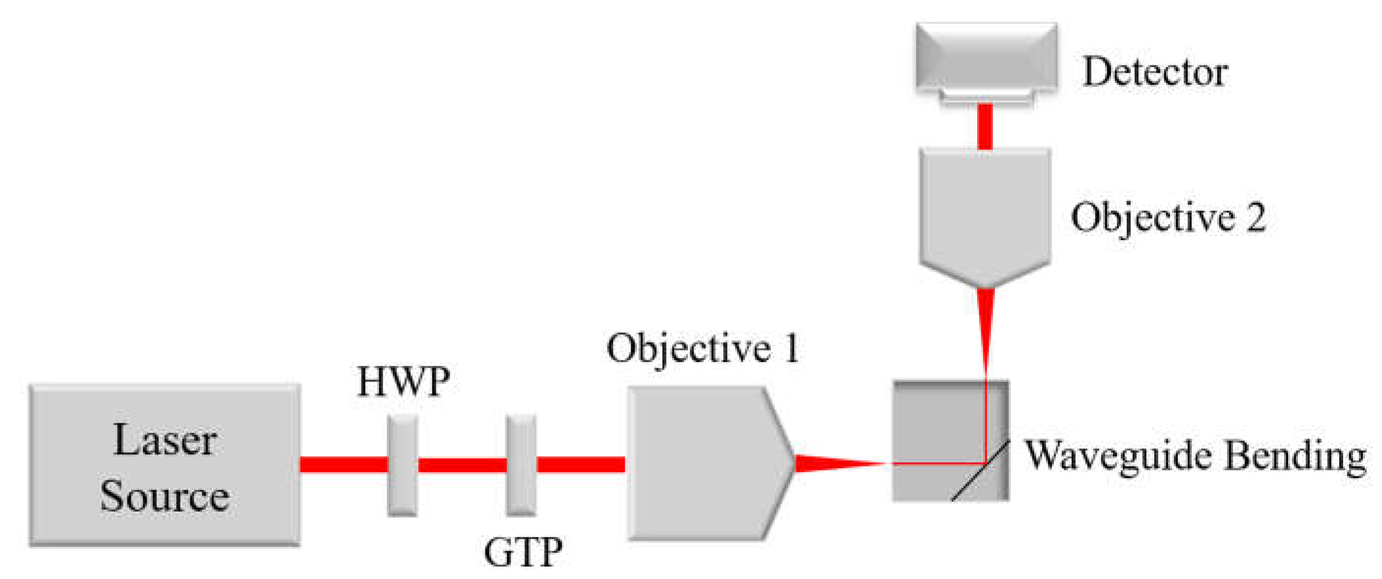
The optical performance of the two groups of waveguides was tested by applying an end–face coupling system as shown in Figure 3. An objective lens with an NA of 0.65 was used to couple the 632.8 nm laser beam from a visible He-Ne source into the input waveguide, and another objective lens (NA = 0.4) lying in the perpendicular direction was used to collect the near field profile from the bent waveguide as output. During the test, a pair of half wave plates (HWP) and a Glan-Taylor polarizer (GTP) were introduced to control the polarization state of the beam.
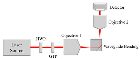
Figure 3.
The end-face coupling setup.
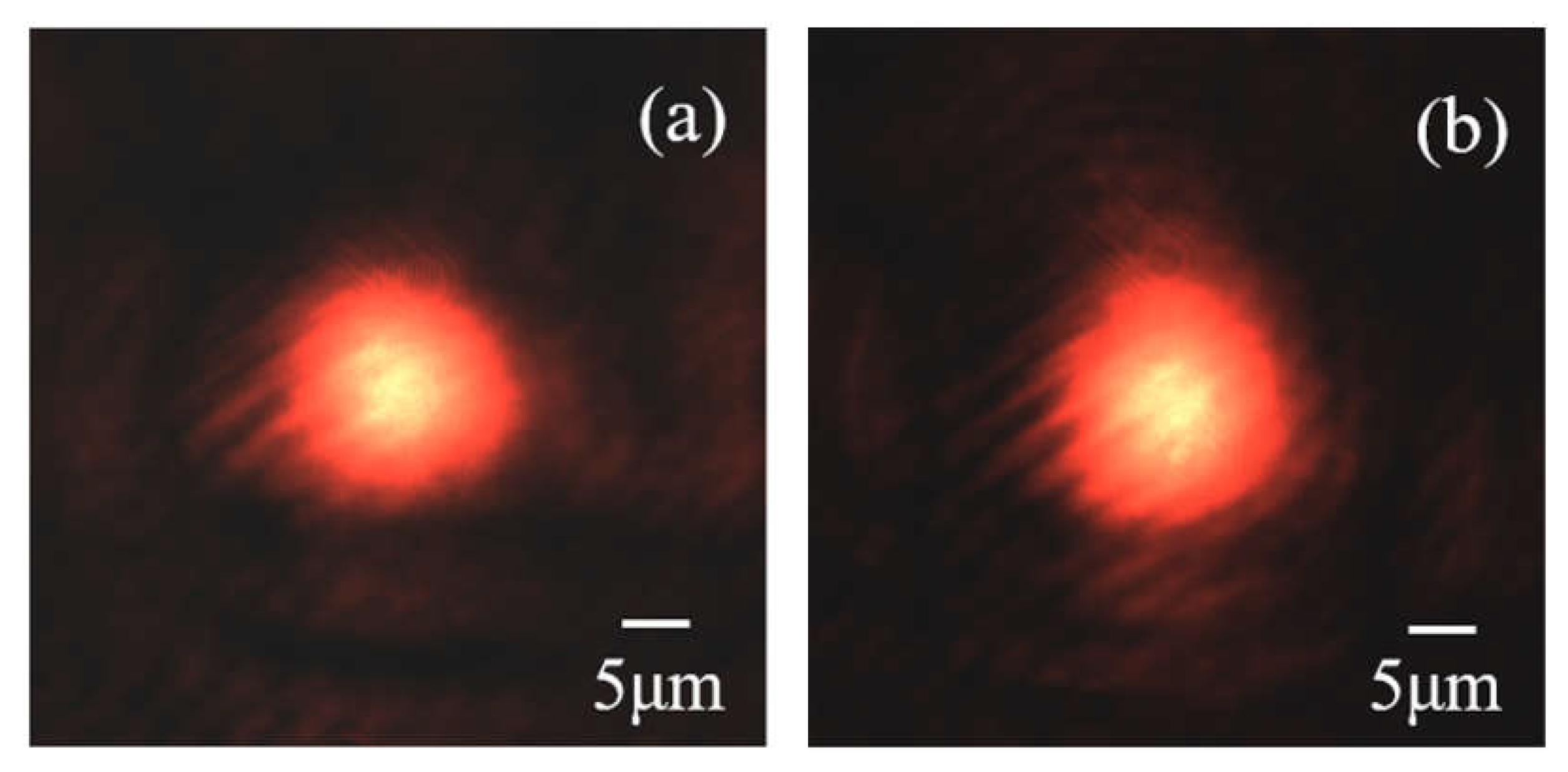
The output near-field profile of the waveguide with a width of 20 μm and a depth of 50 μm under TM polarization is shown in Figure 4a. For comparison, the near-field of a straight waveguide inscribed with the same parameters is also presented in Figure 4b. It is obvious that the mode energy of the input waveguides has been bent by 90° and both input and output waveguides only support the fundamental mode propagation. It should be noted that the near-field distribution under TE polarization is similar to that of TM polarization.
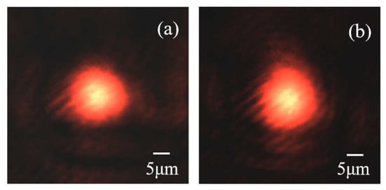
Figure 4.
(a) The intensity distribution obtained from the output waveguide under 632.8 nm and (b) The near-field of a straight waveguide for comparison.
In order to further study the optical performance of the bending waveguides, the finite difference time domain (FDTD) method was applied by using the commercial software Fullwave module, Rsoft (Host ID: 16850650). The change of RI caused by type II fs inscription can be divided into a decrease in RI in the track and a stress-induced local RI increment in the center area between the double lines, both set with Gaussian distribution, as shown in Figure 5b. The microscopic image of the waveguide cross-section is also shown in Figure 5a for comparison. The details of the reconstruction of the cross-sectional RI profile are similar to those in ref [24]. To determine the magnitude of the RI increment, the numerical aperture was measured, and the RI increase was calculated by the following Formula (1):
in which is the maximum incidence angle permitted for mode excitation and is the index of the substrate [25,26]. During the simulation, the grid sizes for all xyz orientations were set to 70 nm, for which a good convergence of the results was confirmed. The bending efficiency was determined by calculating the overlap integral in-between the output beam and the input mode profile, with the mode profile decided by applying the finite element method (FEM) calculation.

Figure 5.
(a) The micrograph of the inscribed waveguide cross–section. (b) The RI profile of the waveguide cross–section used in FDTD simulation; and (c) The reconstructed RI distribution of the waveguide crossing, with black indicating the air.
Based on the measurements, the RI increase between the double lines was determined to be = 5 × 10⁻⁴. The magnitude of the RI reduction in the fs tracks was set to 3 × 10⁻³, according to a previous report [25,27]. It should be noted that the exact value of index reduction had little influence on the following calculation as it only had a slight influence on the mode size. The waveguide crossing area was treated with simply overlaid index distribution, as shown in Figure 5c. The crossing of waveguides is not inevitable, for example, the inscription of both waveguides can be stopped 20 μm before the trench wall. The purpose of crossing is to better estimate the misalignment of the input/output waveguides under the microscope and for easy construction of the CAD modal on the micro-machining platform. It will be seen below that the index fluctuation of the crossing region has negligible influence on the waveguide bending performance.
The calculated field profile (TM polarization) is shown in Figure 6a, with the arrow indicating the direction of propagation. Compared with the input light field, the output field profile is almost constant. The bending efficiency, which was defined as the ratio between output and input mode power, was determined to be 99.80%, indicating that the bending waveguide has good optical performance. It is obvious that the index fluctuation caused by the overlap of the pair of double-line structures has a negligible influence on the bending efficiency. The tiny ripples at the bend area are due to the interference between the input and output beam as the electric fields both lay in the z–direction.

Figure 6.
(a) Calculated electric field distribution under TM polarization; (b) Schematic diagram of output waveguide mismatch ; and (c) The transmission losses of the waveguide bending with different deviations.
As the precise locating of the waveguide crossing point onto the trench edge is difficult, a study on fabrication tolerance is necessary. Here, is defined as the mismatch of the output waveguide in the horizontal direction as shown in Figure 6b. The bending loss variation with is presented in Figure 6c. It is obvious that with the increase in , bending losses increased. It is also noteworthy that the bending efficiency of the waveguide was still larger than 75% when = ±3 µm. The results show that the bending waveguide has good fabrication tolerance, benefiting from the relatively large modal size of the fs-inscribed waveguide.
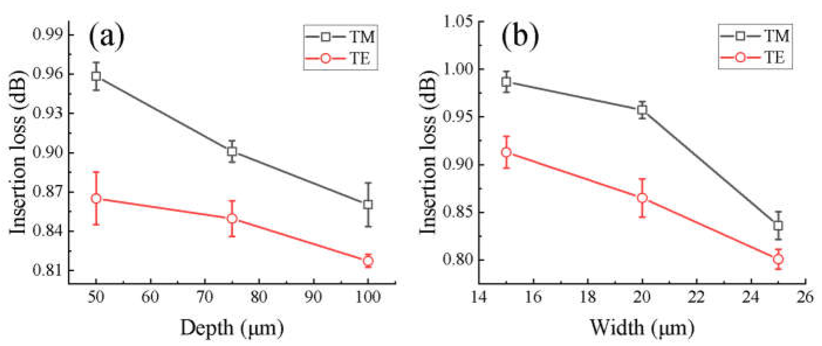
The insertion loss of each waveguide bending was experimentally determined by applying the same end-face coupling setup as shown in Figure 3. To eliminate the impact of coupling or propagation loss for the determination of bending efficiency, different sets of straight waveguides with the same length as the bending waveguides were inscribed in a 15.0 mm length Nd:YAG sample. The loss measurement was repeated 10 rounds for each waveguide bend. During each measurement, the displacement between the objective and the waveguide was adjusted until the output power reached its maximum to insure a similar in-coupling efficiency for each measurement. The averaged results are presented in Figure 7a,b, with a 632.8 nm He-Ne laser as the source. It can be seen that for all the waveguide bends with different widths and depths, the bending efficiency was above 83% (~0.8 dB loss), showing acceptable bending performance. The bending losses of the waveguide were at a similar level as the one previously reported which used the polished edges of bulk crystal as the corner mirror, indicating that diamond dicing can be used as an alternative method for the fabrication of corner mirrors. The propagation loss of the straight waveguide inscribed was also estimated by excluding the in- and out-coupling losses, as well as with the Fresnel reflection loss on the input surface from the total insertion loss, in which the in-coupling loss was determined by calculating the overlap integral in-between the input focused beam spot and the waveguide mode profile. The resulting propagation losses were 4.37 and 4.20 dB/cm for TE and TM polarizations, respectively. The propagation losses can be reduced by further optimizing the laser writing parameters or by introducing post-processed thermal annealing. Different from the previously reported femtosecond laser-induced double-line waveguides in crystalline materials which only support TM polarized mode propagation, in this work, both TE and TM modes of propagation with similar propagation losses were achieved [28,29]. The polarization insensitivity of the waveguide may be due to the circularly polarized fs beam used for laser inscription, which causes isotropy of the laser-modified region [30]. Further experimental demonstrations to study this possibility will be made in the future.
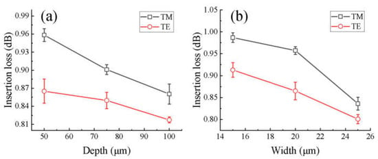
Figure 7.
The transmission losses of waveguide bending with different (a) waveguide depths and (b) waveguide widths. Red and black indicate the results of TE and TM polarizations, respectively. Error bars are also given.
It can be seen from Figure 7a that the transmission loss decreases slightly with increasing inscription depth. The actual tilting angle of the side wall increases with depth, and the maximum tilting angle is ~1.2° at a 100 µm depth. According to the refractive index increase in the waveguide (5 × 10⁻⁴), this tilting angle is still within the N.A. range (~1.62°) of the output waveguide so the influence of the waveguide depth can be ignored. The tilting angle is caused by the arc-like outer shape of the diamond blade, which can be avoided by applying an additional grinding process onto the blade and reshaping it before the trench dicing.
In addition, as shown in Figure 7b, the transmission loss also decreases slightly with increasing waveguide width. The reason for this is that in the case of the same mismatch, the waveguide with a larger width has a larger mode field size, so the fabrication tolerance will be better. In addition to the influence of the tilting angle of the trench, the mechanism of the bending loss may include the unperfect sidewall smoothness, the misalignment of the waveguide pair compared to the trench edge, and the etching effect when the fs beam is focused onto the sidewall, which may cause additional surface roughness. The bending loss may be reduced by further optimizing the dicing and fs writing parameters. We have also tested the polarization-dependency property of the corner mirror, by measuring the power of the TM (TE) polarized bending beam with the TE (TM) input energy. For both cases, the ratio between the output and input power is below 0.1%, showing negligible birefringence of the corner mirror.
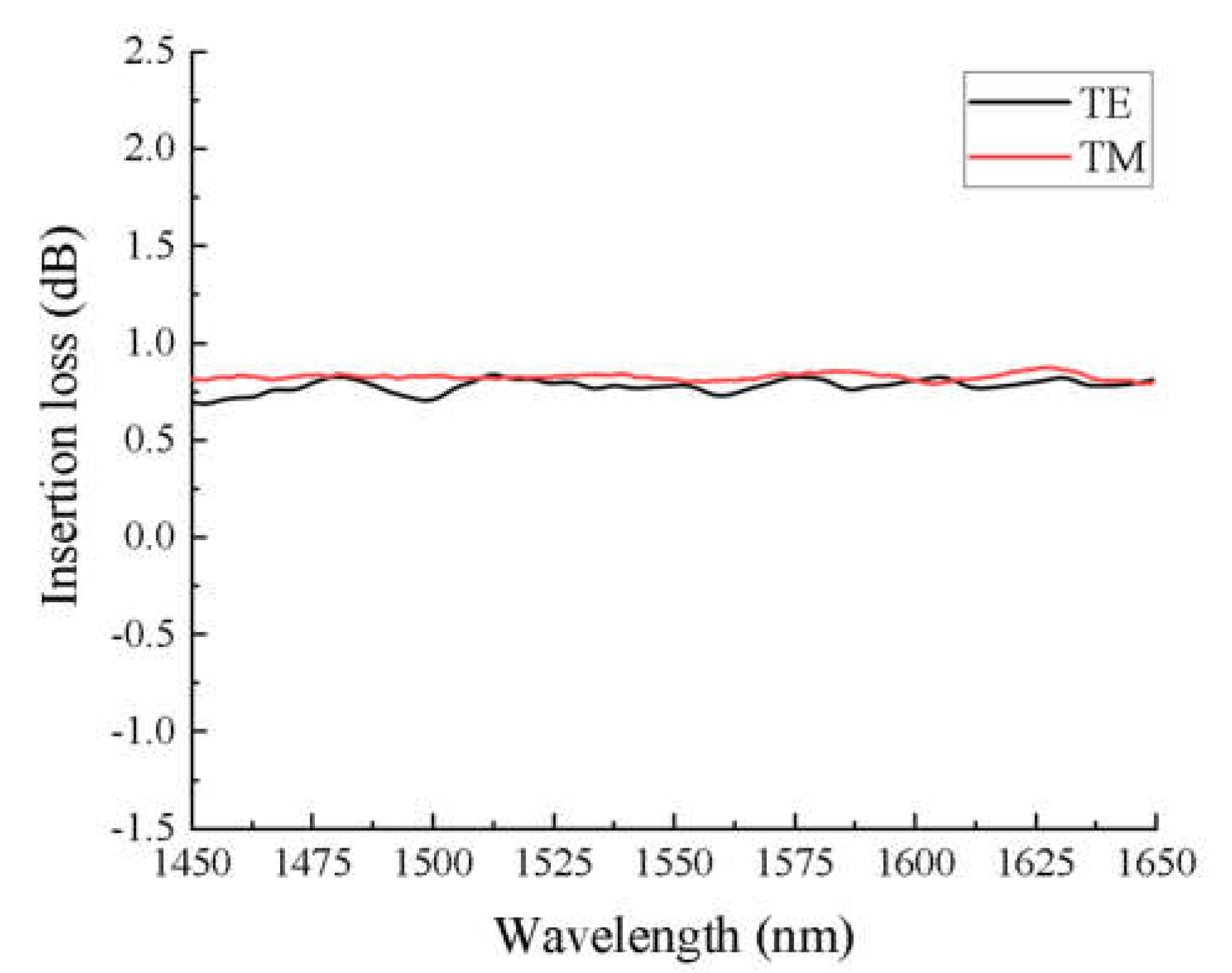
The performance of the waveguide in the 1450–1650 nm infrared band was also tested with a super luminescence diode (SLD) as the light source. The result is shown in Figure 8, with the transmission spectrum normalized to a straight waveguide under the same polarization state. The transmission loss is maintained at a relatively stable level throughout the wavelength range, with the average loss value in this wavelength range being 0.75 dB for TE and 0.79 dB for TM polarization; the transmission losses of different polarizations are relatively close to each other. In addition, the waveguide loss at long wavelengths is slightly lower than that at 632.8 nm. This is because, for lengthier wavelengths, the overlapping integral between input and output modes under similar deviation levels is larger. Another reason could be the insensitivity of the longer wavelength light to the roughness of the trench sidewalls
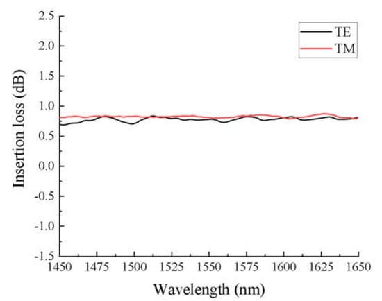
Figure 8.
The transmission spectrum of the bending waveguide in the 1450–1650 nm band.
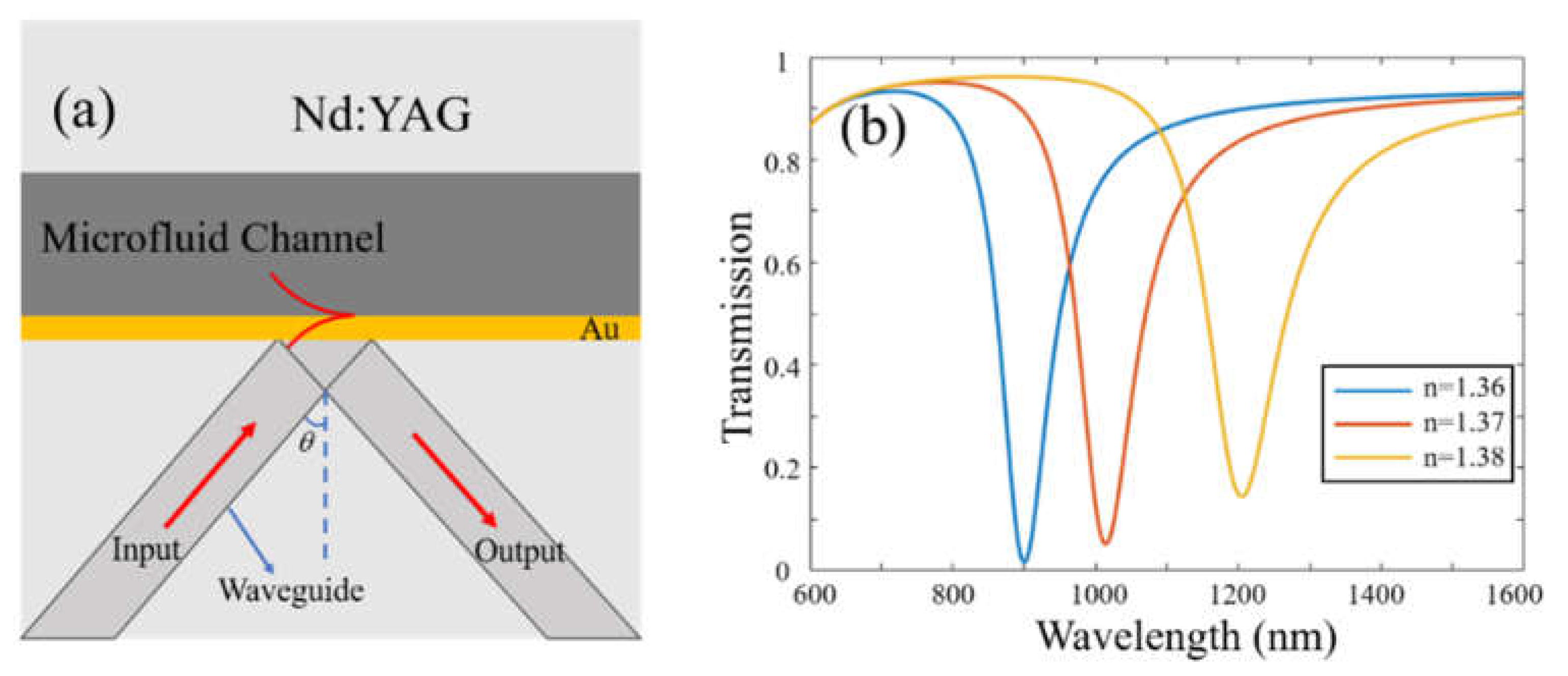
One of the intriguing potential applications of the proposed waveguide bending is refractive index sensing based on surface plasmon resonance (SPR). The working principle is presented in Figure 9a. One trench side wall was deposited with 50 nm thick gold film, with the trench itself acting as a microfluid channel to support the surface wave among the interface between the gold film and the liquid. As the incident angle can be adjusted, combined with the proper choice of high refractive index crystal substrates, the phase matching condition between the input beam and the surface plasmons is easy to achieve, which could enlarge the index detection range and lead to a much higher sensitivity compared with traditional waveguide SPR sensor based on the evanescent field interaction. The results of the theoretical calculation are shown in Figure 9b, in which the transmission spectra obtained based on three different liquid indexes are given. Here, the incident angle was fixed to 50°. The calculation was performed by applying the transfer matrix method, and the Drude dispersion curve was applied to the gold film. As can be seen, for the index ranging from 1.36 to 1.38, the average index sensitivity was as high as 15,200 nm/RIU which is 1 order of magnitude larger than the existing evanescent coupled waveguide SPR sensor (<1500 nm/RIU) [31]. The biochemical sensing function could be realized by modifying probe molecules on the surface of the gold film via a layer-by-layer assembly technique. Different species of probes as antibodies and oligonucleotides could be utilized for the detection of protein, RNA, DNA, et al. The addition of functional nanomaterials such as metal nanoparticles and graphene has also been shown to lead to an even higher sensitivity [32,33]. Experimental demonstrations will be carried out in future works.
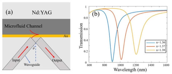
Figure 9.
(a) The working principle of the SPR sensor; (b) The transmission spectrum of the output waveguide with three different liquid indexes of 1.36, 1.37, and 1.38.
4. Conclusions
To summarize, the 90° bending of stress-induced waveguides in Nd:YAG crystals were achieved by a combination of femtosecond laser inscription and precise diamond blade dicing technology. The bent waveguides had a good optical performance, with bending efficiencies of more than 83% under both TE and TM polarizations. The FDTD simulation was used to further study the optical performance of the bent waveguides, and it was found that the waveguide has excellent fabrication tolerance, with losses as low as 1.2 dB even at a horizontal mismatch of 3 μm for the waveguide crossing relative to the mirror edge. The same strategy can be implemented for the depressed cladding waveguides, as different ordered modes can propagate independently without cross-talk when bent by a corner mirror. One of the main drawbacks of this method is the relatively large trench size (more than 4 mm long with a dicing depth of 50 μm), as the outer diameter of the blade used is 52 mm. However, the trench mirror is still useful, for example, for increasing the cavity length of waveguide lasers and for the construction of novel waveguide micro-fluid sensors. This method provides great flexibility and potential in the design of integrating optical devices.
Author Contributions
Conceptualization, Y.Y.; methodology, L.Z. and T.L.; software, Y.Y.; investigation, H.Z.; writing original draft preparation, H.Z.; writing review and editing, Y.R. and Y.J.; supervision, Y.Y., M.W., N.C. and C.B.; funding acquisition, Y.Y., L.Z., N.C., C.B., Y.R. and T.L. All authors have read and agreed to the published version of the manuscript.
Funding
This research was funded by the National Natural Science Foundation of China, grant number 11874243, 11805108; by the Natural Science Foundation of Shandong Province, grant number ZR2020QF86, ZR2022MF253; and by Liaocheng University, grant number 318051411, 31805180101, 318052199.
Institutional Review Board Statement
Not applicable.
Informed Consent Statement
Not applicable.
Data Availability Statement
Data available on request.
Acknowledgments
The authors thank DISCO HI–TEC CHINA Co., Ltd. for providing the dicing services.
Conflicts of Interest
The authors declare no conflict of interest.
References
- Lv, J.; Cheng, Y.; Lu, Q.; de Aldana, J.R.V.; Hao, X.; Chen, F. Femtosecond laser written optical waveguides in z-cut MgO:LiNbO3 crystal: Fabrication and optical damage investigation. Opt. Mater. 2016, 57, 169–173. [Google Scholar] [CrossRef]
- Apostolopoulos, V.; Laversenne, L.; Colomb, T.; Depeursinge, C.; Salathé, R.; Pollinau, M.; Osellame, R.; Cerullo, G.; Laporta, P. Femtosecond-irradiation-induced refractive-index changes and channel waveguiding in bulk Ti3+: Sapphire. Appl. Phys. Lett. 2004, 85, 1122–1124. [Google Scholar] [CrossRef]
- Jia, Y.; Wang, S.; Chen, F. Femtosecond laser direct writing of flexibly configured waveguide geometries in optical crystals: Fabrication and application. Opto-Electron. Adv. 2020, 3, 190042. [Google Scholar] [CrossRef]
- Sun, X.; Dong, X.; Hu, Y.; Li, H.; Chu, D.; Zhou, J.; Wang, C.; Duan, J.A. A robust high refractive index sensitivity fiber Mach–Zehnder interferometer fabricated by femtosecond laser machining and chemical etching. Sens. Actuat. A-Phys. 2015, 230, 111–116. [Google Scholar] [CrossRef]
- Ringleb, S.; Rademaker, K.; Nolte, S.; Tünnermann, A. Monolithically integrated optical frequency converter and amplitude modulator in LiNbO3 fabricated by femtosecond laser pulses. Appl. Phys. B-Lasers O 2010, 102, 59–63. [Google Scholar] [CrossRef]
- Liao, Y.; Xu, J.; Cheng, Y.; Zhou, Z.H.; He, F.; Sun, H.Y.; Song, J.; Wang, X.S.; Xu, Z.Z.; Sugioka, K.; et al. Electro-optic integration of embedded electrodes and waveguides in LiNbO3 using a femtosecond laser. Opt. Lett. 2008, 33, 2281–2283. [Google Scholar] [CrossRef] [PubMed]
- Ling, T.; Liu, L.; Song, Q.; Xu, L.; Wang, W. Intense directional lasing from a deformed square-shaped organic-inorganic hybrid glass microring cavity. Opt. Lett. 2003, 28, 1784–1786. [Google Scholar] [CrossRef] [PubMed]
- Skryabin, N.; Kalinkin, A.; Dyakonov, I.; Kulik, S. Femtosecond laser written depressed-cladding waveguide 2 × 2, 1 × 2 and 3 × 3 directional couplers in Tm3+:YAG crystal. Micromachines 2019, 11, 1. [Google Scholar] [CrossRef] [PubMed]
- Zhao, L.; Jiang, L.; Wang, S.; Xiao, H.; Lu, Y.; Tsai, H.L. A high-quality Mach-Zehnder interferometer fiber sensor by femtosecond laser one-step processing. Sensors 2011, 11, 54–61. [Google Scholar] [CrossRef] [PubMed]
- Feng, T.; Sahoo, P.; Arteaga-Sierra, F.; Dorrer, C.; Qiao, J. Pulse-propagation modeling and experiment for femtosecond-laser writing of waveguide in Nd:YAG. Crystals 2019, 9, 434. [Google Scholar] [CrossRef]
- Ródenas, A.; Torchia, G.A.; Lifante, G.; Cantelar, E.; Lamela, J.; Jaque, F.; Roso, L.; Jaque, D. Refractive index change mechanisms in femtosecond laser written ceramic Nd:YAG waveguides: Micro-spectroscopy experiments and beam propagation calculations. Appl. Phys. B-Lasers O 2009, 95, 85–96. [Google Scholar] [CrossRef]
- Pätzold, W.M.; Demircan, A.; Morgner, U. Low-loss curved waveguides in polymers written with a femtosecond laser. Opt. Express 2017, 25, 263–270. [Google Scholar] [CrossRef] [PubMed]
- Wang, Y.; Dai, D. Multimode silicon photonic waveguide corner-bend. Opt. Express 2020, 28, 9062–9071. [Google Scholar] [CrossRef]
- Lv, J.; Bai, J.; Zhou, K.M.; Mei, X.S.; Wang, K.D.; Li, M.; Cheng, G.H. Transmission performance of 90 degrees-bend optical waveguides fabricated in fused silica by femtosecond laser inscription. Opt. Lett. 2017, 42, 3470–3473. [Google Scholar] [CrossRef] [PubMed]
- Bruske, D.; Suntsov, S.; Ruter, C.E.; Kip, D. Efficient ridge waveguide amplifiers and lasers in Er-doped lithium niobate by optical grade dicing and three-side Er and Ti in-diffusion. Opt. Express 2017, 25, 29374–29379. [Google Scholar] [CrossRef]
- Wang, Y.; Shen, X.L.; Zhu, Q.F.; Liu, C.X. Optical planar and ridge waveguides in terbium gallium garnet crystals produced by ion implantation and precise diamond blade dicing. Opt. Mater. Express 2018, 8, 3288–3294. [Google Scholar] [CrossRef]
- Sun, J.; Gan, Y.C.; Xu, C. Efficient green-light generation by proton-exchanged periodically poled MgO:LiNbO3 ridge waveguide. Opt. Lett. 2011, 36, 549–551. [Google Scholar] [CrossRef]
- Courjal, N.; Guichardaz, B.; Ulliac, G.; Rauch, J.Y.; Sadani, B.; Lu, H.; Bernal, M.P. High aspect ratio lithium niobate ridge waveguides fabricated by optical grade dicing. J. Phys. D Appl. Phys. 2011, 44, 305101. [Google Scholar] [CrossRef]
- Volk, M.F.; Suntsov, S.; Rüter, C.E.; Kip, D. Low loss ridge waveguides in lithium niobate thin films by optical grade diamond blade dicing. Opt. Express 2016, 24, 1386–1391. [Google Scholar] [CrossRef]
- Suntsov, S.; Rüter, C.E.; Kip, D. Dual parameter fiber-integrated sensor for refractive index and temperature measurement based on Fabry–Perot micro-resonators. Appl. Opt. 2019, 58, 2076–2080. [Google Scholar] [CrossRef]
- Suntsov, S.; Rüter, C.E.; Schipkowski, T.; Kip, D. Fiber-integrated refractive index sensor based on a diced Fabry–Perot micro-resonator. Appl. Opt. 2017, 56, 9139–9143. [Google Scholar] [CrossRef] [PubMed]
- Calmano, T.; Paschk, A.G.; Müller, S.; Kränkel, C.; Huber, G. Curved Yb:YAG waveguide lasers, fabricated by femtosecond laser inscription. Opt. Express 2013, 21, 25501–25508. [Google Scholar] [CrossRef] [PubMed]
- Wu, P.F.; Yang, S.C.; Ren, Y.Y.; Liu, H.L. Beam splitters fabricated by nonlinear focusing of femtosecond laser writing in pure YAG crystal. Front. Phys. 2021, 9, 719757. [Google Scholar] [CrossRef]
- Zhang, C.; Dong, N.; Yang, J.; Chen, F.; de Aldana, J.R.V.; Lu, Q. Channel waveguide lasers in Nd:GGG crystals fabricated by femtosecond laser inscription. Opt. Express 2011, 19, 12503–12508. [Google Scholar] [CrossRef] [PubMed]
- Li, S.L.; Ye, Y.K.; Wang, M.W. Femtosecond laser written channel optical waveguide in Nd:YAG crystal. Opt. Laser Technol. 2014, 58, 89–93. [Google Scholar] [CrossRef]
- Li, S.L.; Han, P.G.; Shi, S.; Yao, Y.C.; Hu, B.; Wang, M.W.; Zhu, X.N. Low-loss channel optical waveguide fabrication in Nd3+-doped silicate glasses by femtosecond laser direct writing. Opt. Express 2011, 19, 23958–23964. [Google Scholar] [CrossRef]
- Siebenmorgen, J.; Petermann, K.; Huber, G.; Rademaker, K.; Nolte, S.; Tünnermann, A. Femtosecond laser written stress-induced Nd:Y3Al5O12 (Nd:YAG) channel waveguide laser. Appl. Phys. B 2009, 97, 251. [Google Scholar] [CrossRef]
- Zhang, Y.; Wu, J.; Wang, L.; Chen, F. Femtosecond laser direct writing of Nd:YAG waveguide with Type I modification: Positive refractive index change in track. Opt. Mater. 2021, 113, 110844. [Google Scholar] [CrossRef]
- Sun, X.; Sun, S.; Romero, C.; de Aldana, J.R.V.; Liu, F.; Jia, Y.; Chen, F. Femtosecond laser direct writing of depressed cladding waveguides in Nd:YAG with “ear-like” structures: Fabrication and laser generation. Opt. Express 2021, 29, 4296–4307. [Google Scholar] [CrossRef]
- Beresna, M.; Gecevičius, M.; Lancry, M.; Poumellec, B.; Kazansky, P.G. Broadband anisotropy of femtosecond laser induced nanogratings in fused silica. Appl. Phys. Lett. 2013, 103, 131903. [Google Scholar] [CrossRef]
- Ji, L.; Sun, X.; He, G.; Liu, Y.; Wang, X.; Yi, Y.; Chen, C.; Wang, F.; Zhang, D. Surface plasmon resonance refractive index sensor based on ultraviolet bleached polymer waveguide. Sens. Actuat. B-Chem. 2017, 244, 373–379. [Google Scholar] [CrossRef]
- Chen, L.; Liu, B.; Liu, J.; Yuan, J.H.; Chan, H.P.; Wu, T.; Wang, M.Y.; Wan, S.P.; He, X.D.; Wu, Q. U-shape panda polarization-maintaining microfiber sensor coated with graphene oxide for relative humidity measurement. J. Lighwave Technol. 2021, 39, 6308–6314. [Google Scholar] [CrossRef]
- Wang, J.; Munir, A.; Li, Z. Aptamer-Au NPs conjugates-enhanced SPR sensing for the ultrasensitive sandwich immunoassay. Biosens. Bioelectron. 2009, 25, 124–129. [Google Scholar] [CrossRef] [PubMed]
Disclaimer/Publisher’s Note: The statements, opinions and data contained in all publications are solely those of the individual author(s) and contributor(s) and not of MDPI and/or the editor(s). MDPI and/or the editor(s) disclaim responsibility for any injury to people or property resulting from any ideas, methods, instructions or products referred to in the content. |
© 2023 by the authors. Licensee MDPI, Basel, Switzerland. This article is an open access article distributed under the terms and conditions of the Creative Commons Attribution (CC BY) license (https://creativecommons.org/licenses/by/4.0/).


