Article

Design of Tunable Liquid Crystal Lenses with a Parabolic Phase Profile

School of Optoelectronic Science and Engineering, University of Electronic Science and Technology of China, Chengdu 611730, China
*
Author to whom correspondence should be addressed.
Crystals 2023, 13(1), 8; https://doi.org/10.3390/cryst13010008
Submission received: 1 December 2022 / Revised: 16 December 2022 / Accepted: 17 December 2022 / Published: 21 December 2022
(This article belongs to the Special Issue Advances in Liquid Crystal Optical Devices)

Abstract

:
An electrode pattern design generating a parabolic voltage distribution, in combination with usage of the linear response range of the liquid crystal (LC) material, has been recently proposed to obtain nearly ideal phase profiles for LC lenses. This technique features low driving voltages, simple structure, compact design, and the absence of high-resistivity (HR) layers. In this work, the universal design principle is discussed in detail, which is applicable not only to LC lens design, but also to other LC devices with any phase profile. Several electrode patterns are presented to form a parabolic voltage distribution. An equivalent electric circuit of the LC lens based on the design principle is developed, and the simulation results are given. In the experiments, an LC lens using the feasible parameters is prepared, and its high-quality performance is demonstrated.

1. Introduction

Liquid crystal (LC) is the state of aggregation that possesses the properties of both a crystalline solid and an isotropic liquid [1], which has been extensively researched [2,3,4,5]. The molecular orientation of LC can be controlled with applied electric/magnetic/optical fields leading to the tunable electrical, electro-optical and optical properties [5], allowing for LC to be used in many devices, such as LC displays and LC lenses. The LC lens was first proposed by Sato in 1979 [6] and has been attracting much attention in recent decades [7,8,9,10,11,12,13,14,15,16,17,18]. The focal length of the LC lens is electrically tunable compared with conventional solid lenses. The LC lenses using hole-patterned electrodes have been studied extensively [19,20,21,22,23,24,25], but the substrate between the patterned electrode and the LC layer causes high driving voltages. High-resistivity (HR) layers make the use of the substrate unnecessary, thus making low voltages possible [26,27,28,29,30]. The resistance of the HR layer usually changes over time, which results in the properties of the LC lens becoming unstable. Some other structures, including the use of transmission lines [31,32,33,34,35,36,37], surf relief electrodes [38,39] and lens-shaped dielectric material [40,41,42], have been reported. It is difficult to obtain LC lenses with a parabolic phase profile using these techniques. Multielectrode design makes nearly ideal lens properties possible [43,44,45]; however, too many voltage sources are required to drive the lens [46].
Recently, we proposed [47,48,49,50] forming parabolic voltage distributions using resistive lines and driving the LC lens with voltages within the linear response range of the LC material. An LC lens with a nearly parabolic phase profile is realized and the parabolic phase profile is maintained during focus tuning. In this work, we report several resistive line patterns and discuss the universal design principle in detail. The voltage distribution is simulated, and an LC lens with an aperture of 2 mm is demonstrated. The experimental and simulation results are in agreement.

2. Principle

As shown in Figure 1, suppose a uniform resistive line is applied with voltages V1 and V2 at both ends. The voltage values at N + 1 points on the line are taken and are rearranged at equal intervals to generate the desired voltage distributions determined by the length of the resistive line between these points. For example, if these points are equally spaced, the voltage distribution after rearrangement is linear. In particular, when the length of the resistive line between these points increases linearly, according to Ohm’s law, the voltage value at each point is
V ( n ) = V 1 + i = 1 n ( i 1 ) l i = 1 N + 1 ( i 1 ) l ( V 2 V 1 ) = V 1 + n 2 N ( N + 1 ) ( V 2 V 1 )       ( n = 1 , 2 , 3 , , N + 1 )
where l is the length of the resistive line between the first two points. From Equation (1), we find that the voltage distribution is a parabolic function of point index n. After rearranging these points equidistantly along the x-axis, the voltage distribution is the parabolic function of x.
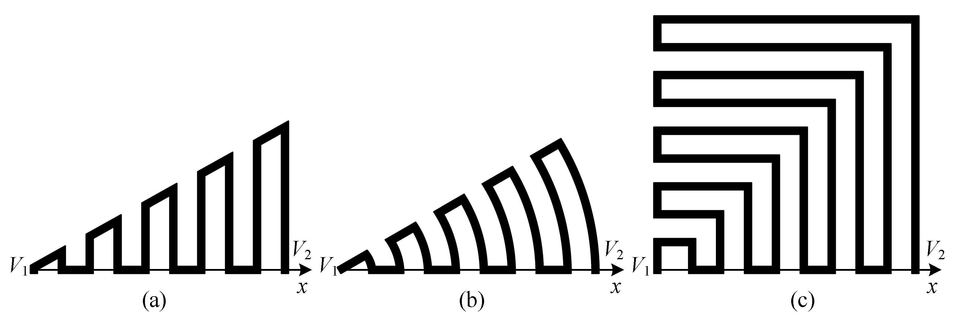
In fact, a parabolic voltage distribution can be obtained without considering the shape of the resistive line as long as the length of the resistive line between these points increases linearly from zero. Thus, we can design the shape of the resistive line to make the electrode more compact and avoid the rearrangement process. Several examples are shown in Figure 2; they form a parabolic voltage distribution along the x-axis.
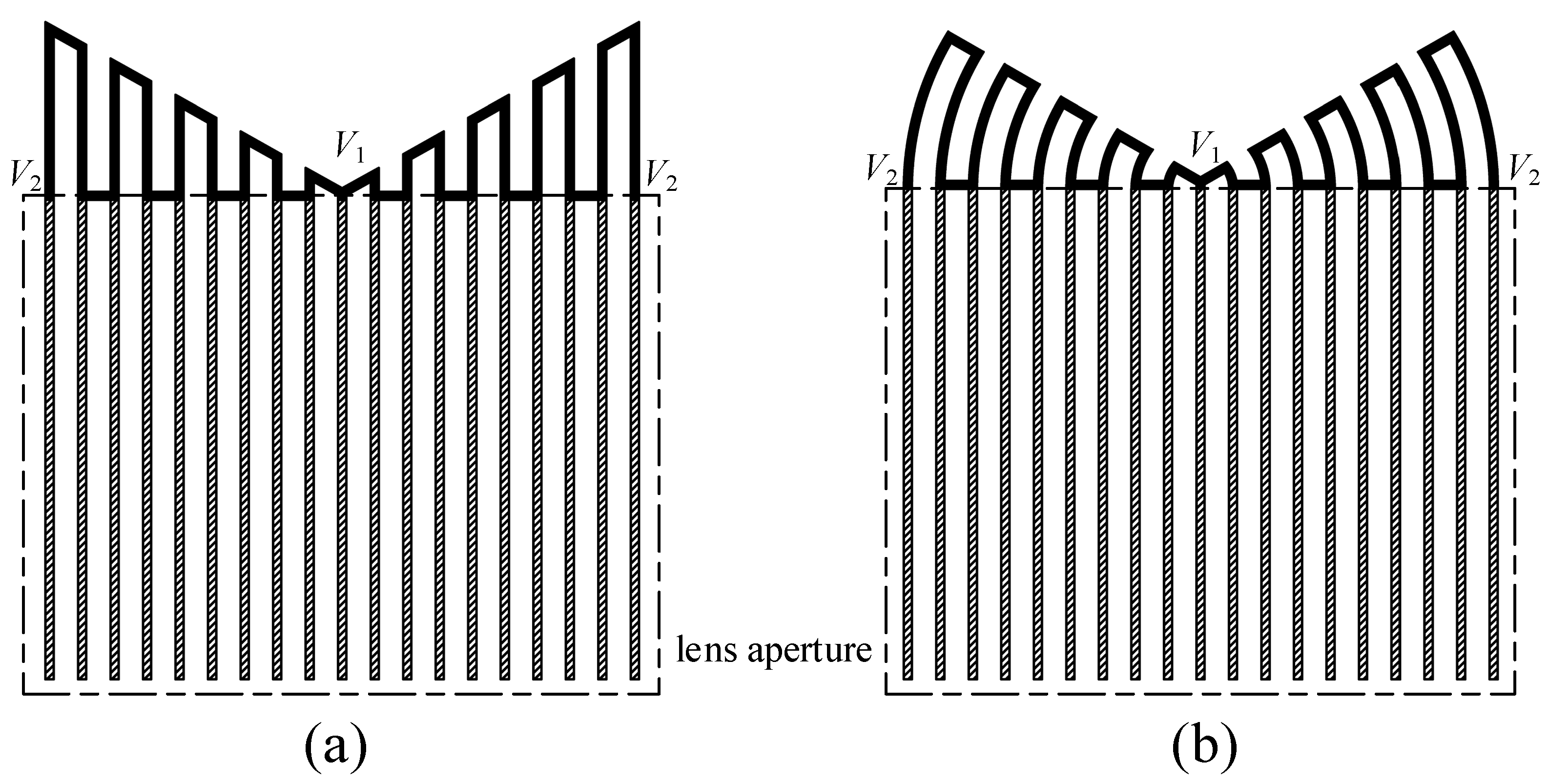
The electrode structures shown in Figure 2 are called a “generating unit”. The parabolic voltage distribution of a generating unit should be distributed over the lens aperture by a “distributing unit”. For a cylindrical LC lens, two identical generating units should be arranged symmetrically to form a symmetrical parabolic voltage distribution, which is then distributed over the lens aperture by a series of parallel ITO electrodes. Taking the first two structures in Figure 2 as examples, the complete electrodes are shown in Figure 3. The solid-filled area represents the resistive line of the generating unit, and the slash-filled area represents the conductive line of the distributing unit.
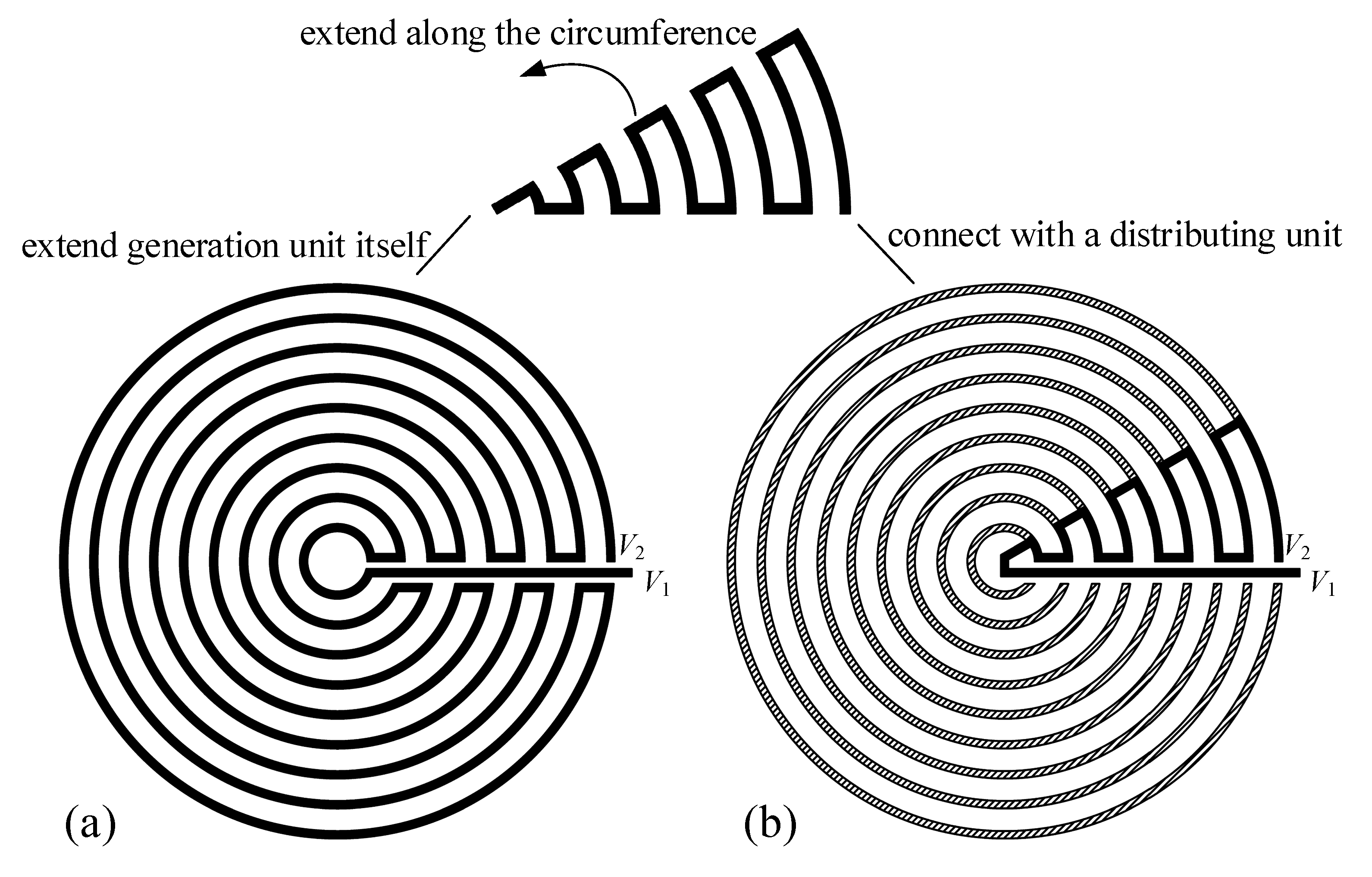
The fan-shaped generating unit shown in Figure 2b can also be used for circular LC lenses, as shown in Figure 4. The first way is to extend the resistive line of the generating unit along the circumferential direction [50], as shown in Figure 4a. The second way is to add an additional distributing unit, as shown in Figure 4b. In both structures, the center is applied with a voltage through an ITO or metal lines. Although there is a voltage drop on the conductive line, it is trivial compared with that on the generating unit. Therefore, the center voltage can be considered to be approximately equal to the externally applied voltage V1.
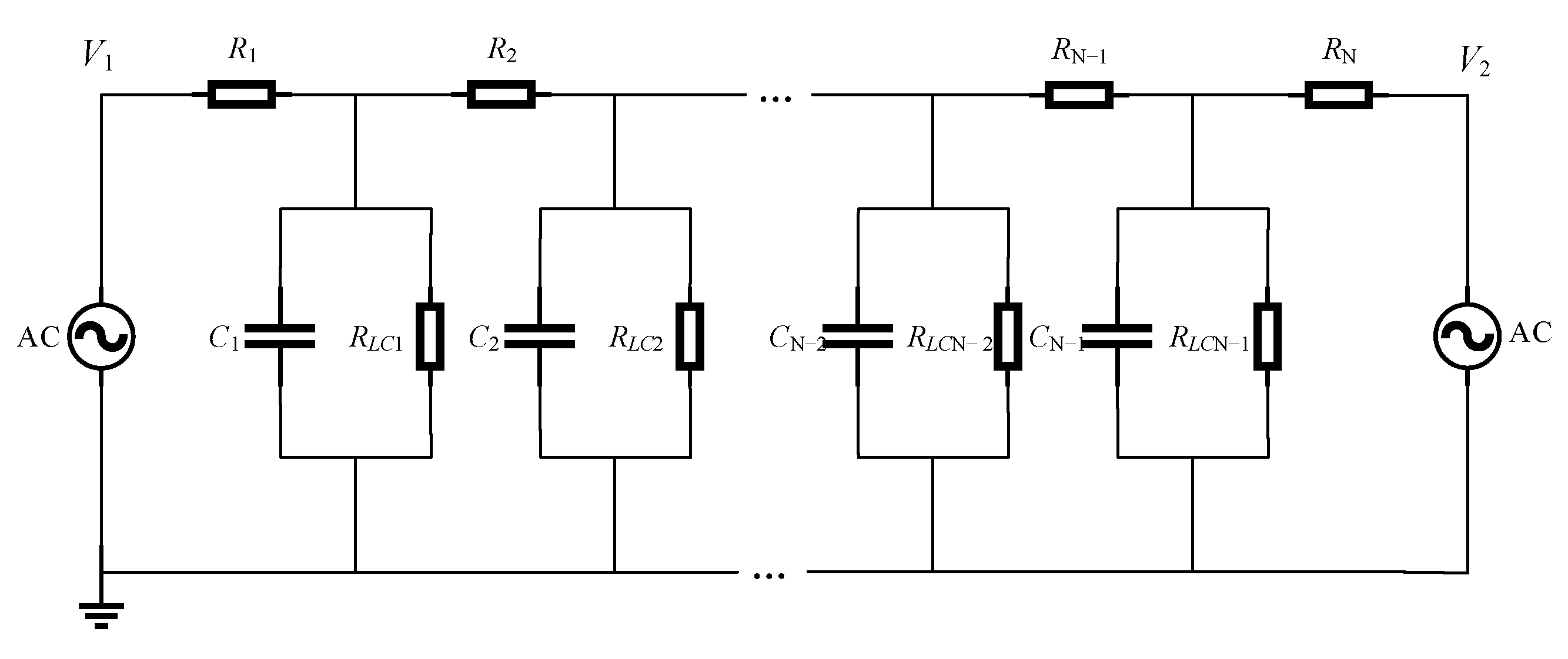
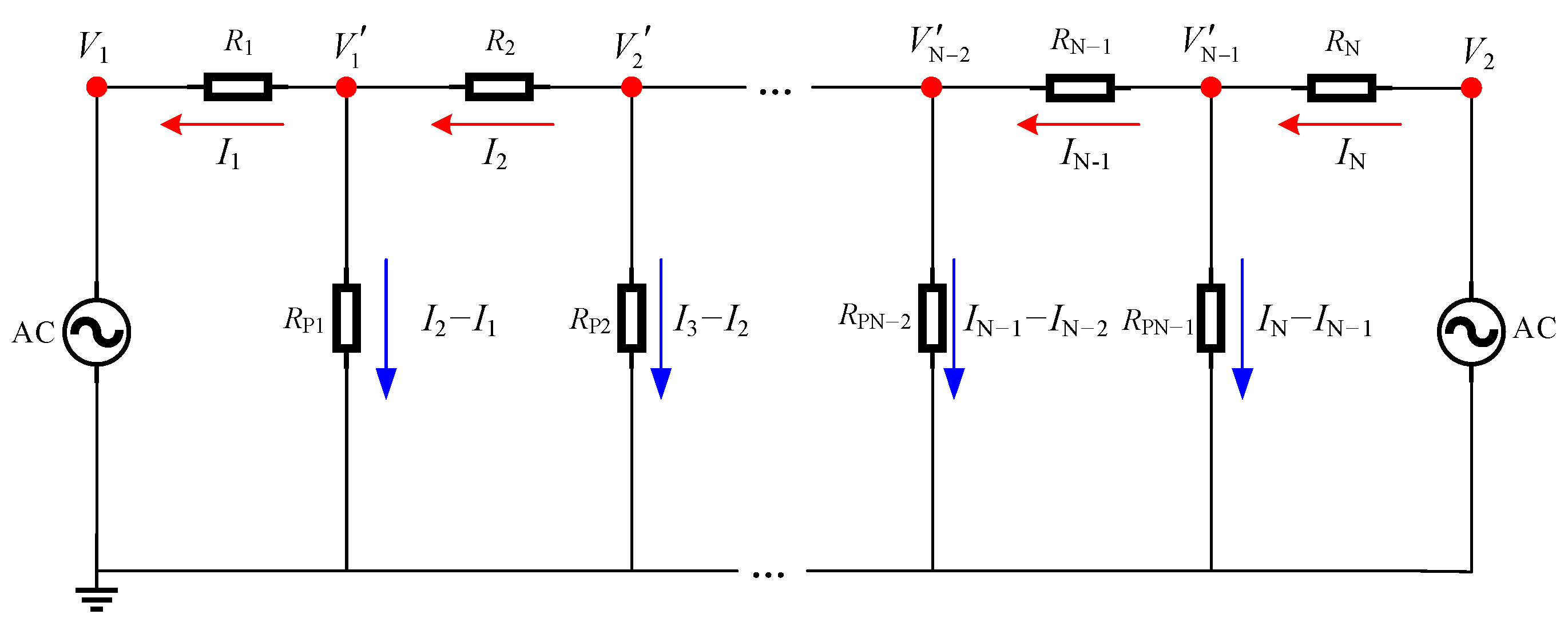
The above-mentioned structures can produce a parabolic voltage distribution, but when they are used in LC lenses, the voltage distribution is affected by the capacitance effect. To analyze the voltage distribution on the electrode pattern, the LC lens is simplified into an equivalent circuit. The electrode pattern in Figure 4a is taken as an example for the analysis. Each concentric ITO line is a resistor, and they are connected in series. Concentric ITO lines form capacitors with the electrode on another substrate, and they are in parallel with the resistance of the LC material. The circuit of an LC lens is shown in Figure 5.
The resistance of the concentric ITO line is
R n = 2 π n ( w + d ) σ e w t       ( n = 1 , 2 , 3 , , N )
where σ e , w , d and t represent the conductivity, width, inter-line gap, and thickness of the ITO electrode, respectively. N = r / ( d + w ) is the number of the concentric ITO line, where r is the radius of the lens aperture. The capacitance is
C n = 2 π n ε 0 ε L C ( w + d ) w T       ( n = 1 , 2 , 3 , , N 1 )
where ε 0 and ε L C represent the vacuum permittivity and the relative permittivity of the LC material, respectively. T is the thickness of the LC layer. The capacitive reactance is expressed as X C n = 1 / ( 2 π f C n ) , and f is the frequency of the voltage signal. The resistance of the LC material between each concentric ITO line and electrode on another substrate is
R L C n = T 2 π n σ L C ( w + d ) w       ( n = 1 , 2 , 3 , , N 1 )
The resistance of the capacitive reactance in parallel with the resistance of the LC material can be expressed as R P n = X C n R L C n / ( X C n + R L C n ) . Then, the circuit in Figure 5 can be further simplified into Figure 6.
We assume current magnitude I n ( n = 1 , 2 , 3 , , N ) and current direction. According to Kirchhoff’s Voltage Law, the following equations can be obtained
{ I 1 R 1 + ( I 2 I 1 ) R P 1 V 1 = 0 I N R N ( I N I N 1 ) R P N 1 + V 2 = 0 I n R n + ( I n + 1 I n ) R P n ( I n I n 1 ) R P n 1 = 0   ( n = 2 , 3 , 4 , , N 1 )
Solving the equations numerically yields all currents, and the node voltages are expressed as
V n = ( I n 1 I n ) R P n       ( n = 1 , 2 , 3 , , N 1 )
According to the above analyses, the voltage distribution under any parameters can be simulated, which provides effective guidance for experiments.

3. Experiments and Results

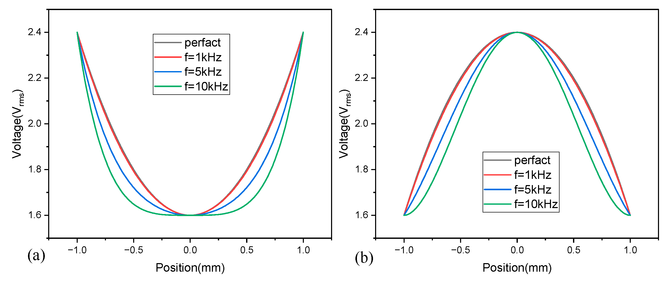
The electrode pattern in Figure 4a is used to fabricate an LC lens, with an aperture size of 2 mm and an LC layer of 30 μm. The parameters of the ITO electrode are w = d = 5   μ m , t = 20   nm , and σ e 10 6   S / m . The positive nematic LC material used in experiments is HSG28800-100 from HCCH Co. Ltd., for which the conductivity is σ L C 10 10 S / m , and the optical refractive indices at a temperature of 25 °C and a wavelength of 589 nm are ne= 1.698, no = 1.499 and Δn = 0.199. The dielectric constants at a frequency of 1kHz are ε = 3.1, ε// = 8.0 and Δε = 4.9. The linear response range of this LC material is measured using the method reported in [47], which is 1.6~2.4 Vrms. Then, the driving voltages are controlled in this range to generate a parabolic phase profile. According to Equations (2)–(6), the voltage distributions in the radial direction of the ITO electrode pattern are calculated when V1 = 1.6 Vrms, V2 = 2.4 Vrms and V1 = 2.4 Vrms, V2 = 1.6 Vrms, respectively. The results are shown in Figure 7. The radial voltage distributions of positive and negative lenses basically follow the parabolic profile when the frequency is 1 kHz, while they gradually deviate from the parabolic profile as the frequency increases. Therefore, voltage signals with a frequency of 1 kHz are used to drive the LC lens in experiments.
The electrode pattern shown in Figure 4a is developed on a glass substrate using a single photolithography step. Then, two substrates (one with an electrode pattern and another with a plane ITO electrode) are cleaned with acetone. The polyimide layer is spun and rubbed on substrates to align the nematic director parallel to the substrate surfaces. Then, two substrates are separated by 30 μm spacers and optically aligned facing each other’s interior surface in opposing directions. Finally, the LC material is injected into the gap between the two substrates and the LC lens is sealed using the UV curing adhesive.
The fabricated LC lens is inserted into an interferometer to capture the interference fringes, the results of which are shown in Figure 8. The dimensions of each image are 801 × 801 pixel. In Figure 8, the schematic illustration of LC directors corresponding to each lens state is also shown. When V1 < V2, the tilt angle of the LC director in the border is larger than that in the center, and positive lenses are formed, as shown in Figure 8a–d. The tilt angle in the border is smaller than that in the center for the negative lens states, as shown in Figure 8e–h. As |V1V2| increases, the number of interference fringes increases. This means the optical power of the lens is electrically tunable and positive–negative switchable. Furthermore, these interference patterns demonstrate the high-quality performance of the LC lens.
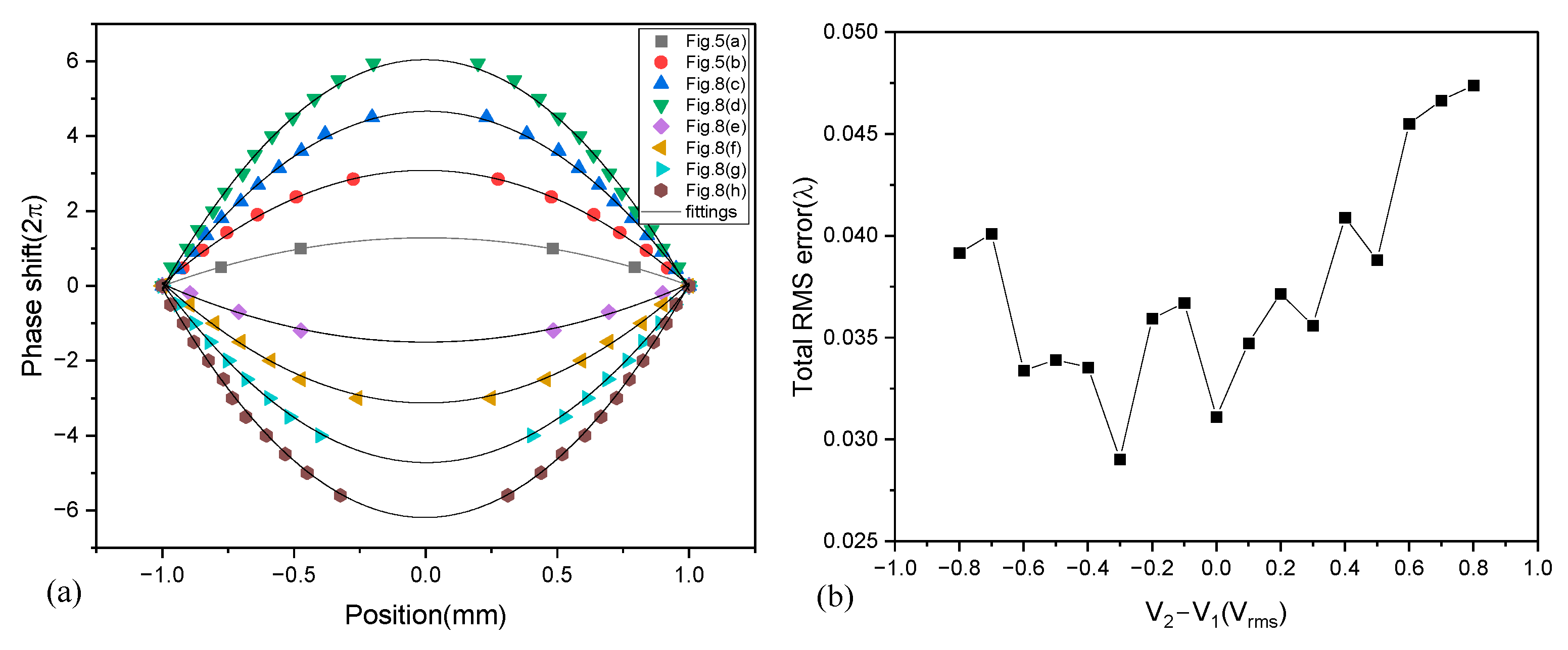
In the interference patterns, the neighboring bright and dark interference fringes have an optical phase difference of π. Therefore, we extract the phase profiles on the horizontal axis of the lens, the results of which are shown in Figure 9a. The symbols are measurements and the curves are parabolic fittings. The phase profiles follow almost parabolic profiles in the whole focus range. The total root-mean-square (RMS) errors of the wavefront are then extracted and are shown in Figure 9b. It can be seen that both positive and negative lenses have a very small RMS error. The positive lens has an RMS maximum around 0.047 λ, while it is 0.040 λ for the negative lens.
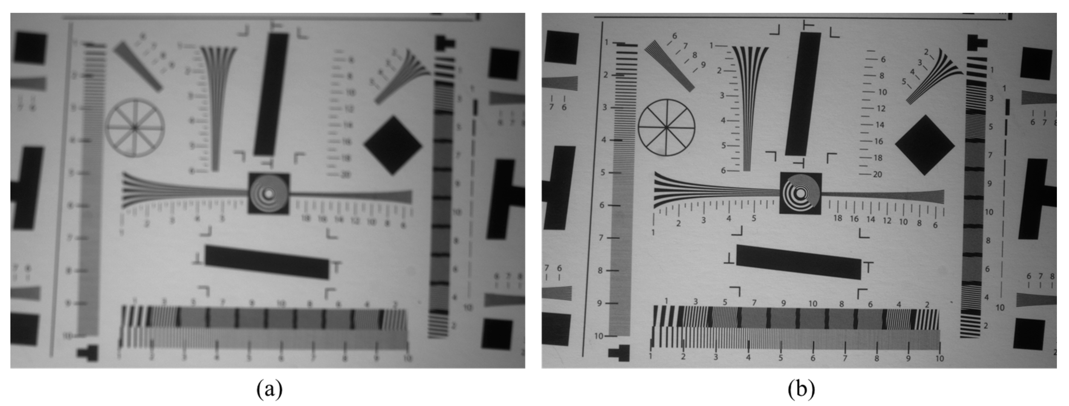
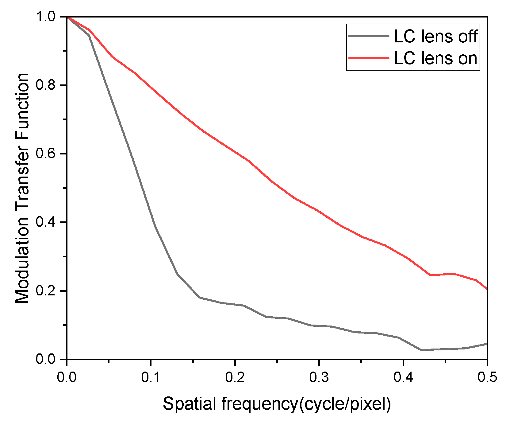
To test the imaging performance of the LC lens, it is inserted into an imaging system with an ISO 12233 chart placed at approximately 19 cm from the CMOS camera. The LC lens is turned off, and the record image (out of focus) is shown in Figure 10a. Then, the LC lens is turned on (V1 = 1.6 Vrms, V2 = 1.9 Vrms), and the image is brought into focus by the positive lens, as shown in Figure 10b. The dimensions of Figure 10a,b are both 2346 × 1623 pixel. The modulation transfer functions (MTFs) are shown in Figure 11. The value of MTF50 is approximately 0.25 when the LC lens is turned on, which confirms the high-quality performance of the LC lens.

4. Conclusions

The principle of the proposed design method is discussed in detail, and several electrode patterns capable of producing a parabolic voltage profile are proposed. The equivalent electric circuit of the LC lens designed using the proposed method is developed. An LC lens with an aperture of 2 mm and LC layer of 30 μm is fabricated. The experimental results show a high-quality performance and small wavefront RMS errors. The proposed design method is applicable not only to LC lens design, but also to other LC devices with any phase profile.

Author Contributions

Conceptualization, W.F. and M.Y.; Methodology, W.F. and M.Y.; Software, W.F.; Investigation, W.F., Z.L. and M.Y.; Formal analysis, W.F., Z.L. and M.Y.; Resources, W.F.; Data Curation, W.F., Z.L. and H.L.; Writing—review and editing, W.F. and M.Y.; Supervision, M.Y.; Project administration, M.Y., W.F. and Z.L.; Funding acquisition, M.Y., W.F. and Z.L.; All authors have read and agreed to the published version of the manuscript.

Funding

Sichuan Province Science and Technology Support Program (2021YJ0102).

Institutional Review Board Statement

Not applicable.

Informed Consent Statement

Not applicable.

Data Availability Statement

Not applicable.

Conflicts of Interest

The authors declare no conflict of interest.

References

  1. Kumar, A.; Singh, D.P.; Singh, G. Recent progress and future perspectives on carbon-nanomaterial-dispersed liquid crystal composites. J. Phys. D Appl. Phys. 2021, 55, 083002. [Google Scholar] [CrossRef]
  2. Khoo, I.C. Nonlinear optics of liquid crystalline materials. Phys. Rep. 2009, 471, 221–267. [Google Scholar] [CrossRef]
  3. Choudhary, A.; Singh, G.; Biradar, A.M. Advances in gold nanoparticle–liquid crystal composites. Nanoscale 2014, 6, 7743–7756. [Google Scholar] [CrossRef] [PubMed]
  4. Singh, G.; Fisch, M.; Kumar, S. Emissivity and electrooptical properties of semiconducting quantum dots/rods and liquid crystal composites: A review. Rep. Prog. Phys. 2016, 79, 056502. [Google Scholar] [CrossRef] [PubMed]
  5. Singh, G. Recent advances on cadmium free quantum dots-liquid crystal nanocomposites. Appl. Mater. Today 2020, 21, 100840. [Google Scholar] [CrossRef]
  6. Sato, S. Liquid-Crystal Lens-Cells with Variable Focal Length. Jpn. J. Appl. Phys. 1979, 18, 1679–1684. [Google Scholar] [CrossRef]
  7. Ye, M.; Sato, S. Liquid crystal lens with focus movable along and off axis. Opt. Commun. 2003, 225, 277–280. [Google Scholar] [CrossRef]
  8. Pishnyak, O.; Sato, S.; Lavrentovich, O.D. Electrically tunable lens based on a dual-frequency nematic liquid crystal. Appl. Opt. 2006, 45, 4576–4582. [Google Scholar] [CrossRef]
  9. Lin, Y.-H.; Chen, H.-S.; Lin, H.-C.; Tsou, Y.-S.; Hsu, H.-K.; Li, W.-Y. Polarizer-free and fast response microlens arrays using polymer-stabilized blue phase liquid crystals. Appl. Phys. Lett. 2010, 96, 113505. [Google Scholar] [CrossRef] [Green Version]
  10. Lin, H.-C.; Lin, Y.-H. An Electrically Tunable Focusing Pico-Projector Adopting a Liquid Crystal Lens. Jpn. J. Appl. Phys. 2010, 49, 102502. [Google Scholar] [CrossRef] [Green Version]
  11. Ren, H.; Xu, S.; Wu, S.-T. Polymer-stabilized liquid crystal microlens array with large dynamic range and fast response time. Opt. Lett. 2013, 38, 3144–3147. [Google Scholar] [CrossRef] [PubMed] [Green Version]
  12. Kawamura, M.; Nakamura, K.; Sato, S. Liquid-crystal micro-lens array with two-divided and tetragonally hole-patterned electrodes. Opt. Express 2013, 21, 26520–26526. [Google Scholar] [CrossRef] [PubMed]
  13. Algorri, J.F.; Urruchi, V.; García-Cámara, B.; Sánchez-Pena, J.M. Liquid Crystal Lensacons, Logarithmic and Linear Axicons. Materials 2014, 7, 2593–2604. [Google Scholar] [CrossRef] [PubMed] [Green Version]
  14. Algorri, J.F.; del Pozo, V.U.; Sanchez-Pena, J.M.; Oton, J.M. An Autostereoscopic Device for Mobile Applications Based on a Liquid Crystal Microlens Array and an OLED Display. J. Disp. Technol. 2014, 10, 713–720. [Google Scholar] [CrossRef] [Green Version]
  15. Chang, Y.-C.; Jen, T.-H.; Ting, C.-H.; Huang, Y.-P. High-resistance liquid-crystal lens array for rotaTable 2D/3D autostereoscopic display. Opt. Express 2014, 22, 2714–2724. [Google Scholar] [CrossRef] [PubMed] [Green Version]
  16. Shibuya, G.; Yoshida, H.; Ozaki, M. High-speed driving of liquid crystal lens with weakly conductive thin films and voltage booster. Appl. Opt. 2015, 54, 8145–8151. [Google Scholar] [CrossRef]
  17. Algorri, J.F.; Urruchi, V.; Bennis, N.; Sanchez-Pena, J.M.; Oton, J.M. Cylindrical Liquid Crystal Microlens Array With Rotary Optical Power and Tunable Focal Length. IEEE Electron Device Lett. 2015, 36, 582–584. [Google Scholar] [CrossRef]
  18. Zhang, Y.; Weng, X.; Liu, P.; Wu, C.; Sun, L.; Yan, Q.; Zhou, X.; Guo, T. Electrically high-resistance liquid crystal micro-lens arrays with high performances for integral imaging 3D display. Opt. Commun. 2020, 462, 125299. [Google Scholar] [CrossRef]
  19. Ye, M.; Sato, S. Optical Properties of Liquid Crystal Lens of Any Size. Jpn. J. Appl. Phys. 2002, 41, L571–L573. [Google Scholar] [CrossRef]
  20. Ye, M.; Wang, B.; Sato, S. Driving of Liquid Crystal Lens without Disclination Occurring by Applying In-Plane Electric Field. Jpn. J. Appl. Phys. 2003, 42, 5086–5089. [Google Scholar] [CrossRef]
  21. Wang, B.; Ye, M.; Sato, S. Liquid crystal lens with focal length variable from negative to positive values. IEEE Photonics Technol. Lett. 2005, 18, 79–81. [Google Scholar] [CrossRef]
  22. Ye, M.; Wang, B.; Kawamura, M.; Sato, S. Fast switching between negative and positive power of liquid crystal lens. Electron. Lett. 2007, 43, 474–476. [Google Scholar] [CrossRef]
  23. Lin, H.-C.; Lin, Y.-H. A fast response and large electrically tunable-focusing imaging system based on switching of two modes of a liquid crystal lens. Appl. Phys. Lett. 2010, 97, 063505. [Google Scholar] [CrossRef] [Green Version]
  24. Lin, H.-C.; Chen, M.-S.; Lin, Y.-H. A Review of Electrically Tunable Focusing Liquid Crystal Lenses. Trans. Electr. Electron. Mater. 2011, 12, 234–240. [Google Scholar] [CrossRef] [Green Version]
  25. Lin, Y.-H.; Wang, Y.-J.; Reshetnyak, V. Liquid crystal lenses with tunable focal length. Liq. Cryst. Rev. 2017, 5, 111–143. [Google Scholar] [CrossRef]
  26. Naumov, A.F.; Loktev, M.Y.; Guralnik, I.R.; Vdovin, G. Liquid-crystal adaptive lenses with modal control. Opt. Lett. 1998, 23, 992–994. [Google Scholar] [CrossRef] [Green Version]
  27. Naumov, A.F.; Love, G.D.; Loktev, M.Y.; Vladimirov, F.L. Control optimization of spherical modal liquid crystal lenses. Opt. Express 1999, 4, 344–352. [Google Scholar] [CrossRef]
  28. Ye, M.; Wang, B.; Sato, S. Realization of liquid crystal lens of large aperture and low driving voltages using thin layer of weakly conductive material. Opt. Express 2008, 16, 4302–4308. [Google Scholar] [CrossRef]
  29. Kotova, S.P.; Patlan, V.V.; Samagin, S.A. Tunable liquid-crystal focusing device. 1. Theory. Quantum Electron. 2011, 41, 58–64. [Google Scholar] [CrossRef]
  30. Kotova, S.P.; Patlan, V.V.; Samagin, S.A. Tunable liquid-crystal focusing device. 2. Experiment. Quantum Electron. 2011, 41, 65–70. [Google Scholar] [CrossRef]
  31. Algorri, J.F.; Morawiak, P.; Zografopoulos, D.C.; Bennis, N.; Spadlo, A.; Rodriguez-Cobo, L.; Jaroszewicz, L.R.; Sanchez-Pena, J.M.; Lopez-Higuera, J.M. Multifunctional light beam control device by stimuli-responsive liquid crystal micro-grating structures. Sci. Rep. 2020, 10, 13806. [Google Scholar] [CrossRef] [PubMed]
  32. Algorri, J.F.; Morawiak, P.; Bennis, N.; Zografopoulos, D.C.; Urruchi, V.; Rodriguez-Cobo, L.; Jaroszewicz, L.R.; Sanchez-Pena, J.M.; Lopez-Higuera, J.M. Positive-negative tunable liquid crystal lenses based on a microstructured transmission line. Sci. Rep. 2020, 10, 10153. [Google Scholar] [CrossRef] [PubMed]
  33. Algorri, J.F.; Morawiak, P.; Zografopoulos, D.C.; Bennis, N.; Spadlo, A.; Rodriguez-Cobo, L.; Jaroszewicz, L.R.; Sanchez-Pena, J.M.; Lopez-Higuera, J.M. Cylindrical and Powell Liquid Crystal Lenses With Positive-Negative Optical Power. IEEE Photonics Technol. Lett. 2020, 32, 1057–1060. [Google Scholar] [CrossRef]
  34. Bennis, N.; Jankowski, T.; Morawiak, P.; Spadlo, A.; Zografopoulos, D.C.; Sánchez-Pena, J.M.; López-Higuera, J.M.; Algorri, J.F. Aspherical liquid crystal lenses based on a variable transmission electrode. Opt. Express 2022, 30, 12237–12247. [Google Scholar] [CrossRef] [PubMed]
  35. Algorri, J.; Zografopoulos, D.; Rodríguez-Cobo, L.; Sánchez-Pena, J.; López-Higuera, J. Engineering Aspheric Liquid Crystal Lenses by Using the Transmission Electrode Technique. Crystals 2020, 10, 835. [Google Scholar] [CrossRef]
  36. Pusenkova, A.; Sova, O.; Galstian, T. Electrically variable liquid crystal lens with spiral electrode. Opt. Commun. 2021, 508, 127783. [Google Scholar] [CrossRef]
  37. Stevens, J.; Galstian, T. Electrically tunable liquid crystal lens with a serpentine electrode design. Opt. Lett. 2022, 47, 910–912. [Google Scholar] [CrossRef]
  38. Wang, B.; Ye, M.; Honma, M.; Nose, T.; Sato, S. Liquid Crystal Lens with Spherical Electrode. Jpn. J. Appl. Phys. 2002, 41, L1232–L1233. [Google Scholar] [CrossRef]
  39. Lin, C.-H.; Chen, C.-H.; Chiang, R.-H.; Jiang, I.-M.; Kuo, C.-T.; Huang, C.-Y. Dual-Frequency Liquid-Crystal Lenses Based on a Surface-Relief Dielectric Structure on an Electrode. IEEE Photonics Technol. Lett. 2011, 23, 1875–1877. [Google Scholar] [CrossRef]
  40. Wang, B.; Ye, M.; Sato, S. Lens of electrically controllable focal length made by a glass lens and liquid-crystal layers. Appl. Opt. 2004, 43, 3420–3425. [Google Scholar] [CrossRef]
  41. Ren, H.; Fan, Y.-H.; Gauza, S.; Wu, S.-T. Tunable-focus flat liquid crystal spherical lens. Appl. Phys. Lett. 2004, 84, 4789–4791. [Google Scholar] [CrossRef]
  42. Ren, H.; Wu, S.-T. Adaptive liquid crystal lens with large focal length tunability. Opt. Express 2006, 14, 11292–11298. [Google Scholar] [CrossRef] [PubMed]
  43. Huang, Y.-P.; Chen, C.-W.; Shen, T.-C. High resolution autostereoscopic 3D display with scanning multi-electrode driving liquid crystal (MeD-LC) Lens. In 2009 SID International Symposium Digest of Technical Papers, Vol XL, Books I–III; Society for Information Display: San Jose, CA, USA, 2009; pp. 336–339. [Google Scholar]
  44. Beeckman, J.; Yang, T.-H.; Nys, I.; George, J.P.; Lin, T.-H.; Neyts, K. Multi-electrode tunable liquid crystal lenses with one lithography step. Opt. Lett. 2018, 43, 271–274. [Google Scholar] [CrossRef] [PubMed] [Green Version]
  45. Shen, T.; Zheng, J.; Shen, C.; Wang, X.; Liu, Y. One-dimensional straight-stripe-electrode tunable self-focusing cylindrical liquid crystal lens to realize the achromatic function in time domain. Optik 2022, 260, 168962. [Google Scholar] [CrossRef]
  46. Li, L.; Bryant, D.; Bos, P.J. Liquid crystal lens with concentric electrodes and inter-electrode resistors. Liq. Cryst. Rev. 2014, 2, 130–154. [Google Scholar] [CrossRef]
  47. Feng, W.; Liu, Z.; Ye, M. Positive-negative tunable cylindrical liquid crystal lenses. Optik 2022, 266, 169613. [Google Scholar] [CrossRef]
  48. Feng, W.; Ye, M. Positive-Negative Tunable Liquid Crystal Lens of Rectangular Aperture. IEEE Photonics Technol. Lett. 2022, 34, 795–798. [Google Scholar] [CrossRef]
  49. Feng, W.; Liu, Z.; Ye, M. Liquid crystal lens array with positive and negative focal lengths. Opt. Express 2022, 30, 28941. [Google Scholar] [CrossRef]
  50. Feng, W.; Liu, Z.Q.; Xu, L.; Li, H.; Ye, M. A design method of high-performance liquid crystal lens. Acta Opt. Sin. 2023, 43, 0223001. [Google Scholar]
Figure 1. The schematic diagram of a resistive line.
Crystals 13 00008 g001
Figure 2. Several electrode patterns to form a parabolic voltage distribution. (a) triangle, (b) fan-shaped, and (c) rectangle.
Crystals 13 00008 g002
Figure 3. The electrode patterns of cylindrical LC lenses based on different generating units. (a) triangle type and (b) fan-shaped type.
Crystals 13 00008 g003
Figure 4. Two kinds of electrode patterns of a circular LC lens extended from the fan-shaped generating unit: (a) extend the resistance line of the generating unit itself, or (b) connect with a distributing unit.
Crystals 13 00008 g004
Figure 5. The equivalent circuit of an LC lens based on the electrode pattern in Figure 4a.
Crystals 13 00008 g005
Figure 6. The further simplified circuit from Figure 5.
Crystals 13 00008 g006
Figure 7. The radial voltage distributions under different frequencies. (a) Positive LC lens V1 = 1.6 VrmsV2 = 2.4 Vrms. (b) Negative LC lens V1 = 2.4 VrmsV2 = 1.6 Vrms.
Crystals 13 00008 g007
Figure 8. Interference fringes and the corresponding schematic illustration of LC directors: (ad) positive-lens states, (eh) negative-lens states. (a) V1 = 1.6, V2 = 1.8, (b) V1 = 1.6, V2 = 2.0, (c) V1 = 1.6, V2 = 2.2, (d) V1 = 1.6, V2 = 2.4, (e) V1 = 1.8, V2 = 1.6, (f) V1 = 2.0, V2 = 1.6 (g) V1 = 2.2, V2 = 1.6 and (h) V1 = 2.4, V2 = 1.6 (Vrms value, f = 1 kHz, λ = 457 nm).
Crystals 13 00008 g008
Figure 9. (a) Phase profile extracted from interference fringes in Figure 8, (b) total RMS error.
Crystals 13 00008 g009
Figure 10. Recorded images when the LC lens is (a) turned off and (b) turned on.
Crystals 13 00008 g010
Figure 11. The modulation transfer functions corresponding to the lens-off and lens-on states.
Crystals 13 00008 g011
Disclaimer/Publisher’s Note: The statements, opinions and data contained in all publications are solely those of the individual author(s) and contributor(s) and not of MDPI and/or the editor(s). MDPI and/or the editor(s) disclaim responsibility for any injury to people or property resulting from any ideas, methods, instructions or products referred to in the content.