Article

Magneto-Optical Spin Hall Effect Regulation at Terahertz Frequencies Based on Graphene–Gold Heterojunction

1
Information Materials and Device Applications Key Laboratory of Sichuan Provincial Universities, Chengdu University of Information Technology, Chengdu 610225, China
2
Chengdu Advanced Metal Materials Industry Technology Research Institute Limited Company, Chengdu 610300, China
*
Author to whom correspondence should be addressed.
Crystals 2023, 13(1), 78; https://doi.org/10.3390/cryst13010078
Submission received: 23 November 2022 / Revised: 26 December 2022 / Accepted: 29 December 2022 / Published: 1 January 2023

Abstract

:
In this paper, we theoretically consider the magneto-optical spin Hall effect of light (MOSHEL) in a graphene–gold heterojunction structure at terahertz frequencies, and determine the maximum value of the transverse shift of the spin Hall effect of light (SHEL) in the designed structure by varying the terahertz frequency, the thickness of the metal layer, the Fermi energy level of the graphene, and the magnetic induction density. When the terahertz frequency was 1.2 THz, the metal layer thickness 50 nm, the Fermi level 0.2 eV, and the magnetic induction density B was 10 T, the SHEL shifts of left-handed circularly polarized (LHCP) and right-handed circularly polarized (RHCP) components was greatest at the critical angle (58°), with as value of 498 μm, 1000 times larger than the visible light. At this point, graphene exhibited a significant magneto-optical effect, dramatically enhancing the splitting extrema of LHCP and RHCP. This structure will provide possibilities for enhancement of the transverse shift and efficient regulation of the optical spin Hall effect within the terahertz range.

1. Introduction

When linearly polarized light reflects in the vertical direction of the incident plane, there is a slight movement; that is, the left-handed and right-handed components of the reflected light at the interface of the waveguide layer undergo a small lateral split perpendicular to the incident surface, dividing into left-handed and right-handed circular polarization; this phenomenon is called the spin Hall effect of light (SHEL) [1,2]. The SHEL shift is usually tiny, representing only a fraction of the wavelength, and is very difficult to measure directly by experiment [3]. The SHEL shift can be experimentally observed with the introduction of weak measurement techniques, while many structures, especially artificially designed nanomaterials and metamaterial waveguides, can increase the transverse splitting of circularly polarized beams [4,5,6,7,8,9].
The terahertz (THz) range is widely defined as the portion of the electromagnetic spectrum from 0.1 to 10 THz, corresponding to vacuum wavelengths of 3000 to 30 μm. This portion of the electromagnetic spectrum lies between the photonic and electronic ranges [10,11]. Graphene is a new two-dimensional material with a single sp2 hybridized atomic layer; it has very high electron mobility and can be studied to observe the integer quantum Hall effect even at room temperature [12]. In the terahertz band, the incidence of the light beam on the graphene layer causes a significant magneto-optical Kerr effect (MOKE), referring to the phenomenon of rotation of the line-polarized light after reflection onto the surface of the magnetized medium [13,14]. The magneto-optical effect an effective method for dynamic control of spin splitting and has been comprehensively studied at a theoretical level [15,16]. SHEL enhanced by the MO effect or controlled by an external magnetic field is known as MOSHEL. The metallic layer generates surface plasmon polaritons (SPP) that are quasiparticles of electromagnetic waves in a collective oscillatory coupling of free electron gases at the interface between materials with positive and negative dielectric constants (usually dielectric and metal). These can propagate only when the resonance conditions involving the incident light are met, allowing the diffraction limit to be broken and localizing the light to the subwavelength dimension, thus achieving an increase in field strength [17,18]. The anomalous Hall effect has been extensively studied and has been observed in ferromagnetic materials [19]. Two extrinsic anomalous Hall effect phenomena have been described: the so-called quantum side jump and skew scattering [20,21]. In this paper, we propose a waveguide structure based on a graphene–gold heterojunction with a larger gradient of refractive index variation between waveguide layers and stronger spin-orbit interactions, which can be expected to enhance effectively the SHEL shift.
In this paper, we present for the first time a prism-coupled graphene–gold heterojunction-based waveguide structure to study the photonic spin Hall effect of reflected light in the terahertz band. At a terahertz frequency of 1.2 THz, the SHEL shift of the beam reached 498 μm, according to analysis of the incident angle and with changes to the graphene parameters and the thickness of the metal layer, providing new application potential for novel terahertz devices. In the following sections, we theoretically analyze the proposed prism-coupled graphene–gold heterojunction multilayer structure and calculate the SHEL shift expressions within this structure. In the subsequent section, we analyze the SHEL distribution under different physical parameters based on the simulation results. Finally, we present the conclusion of this paper.

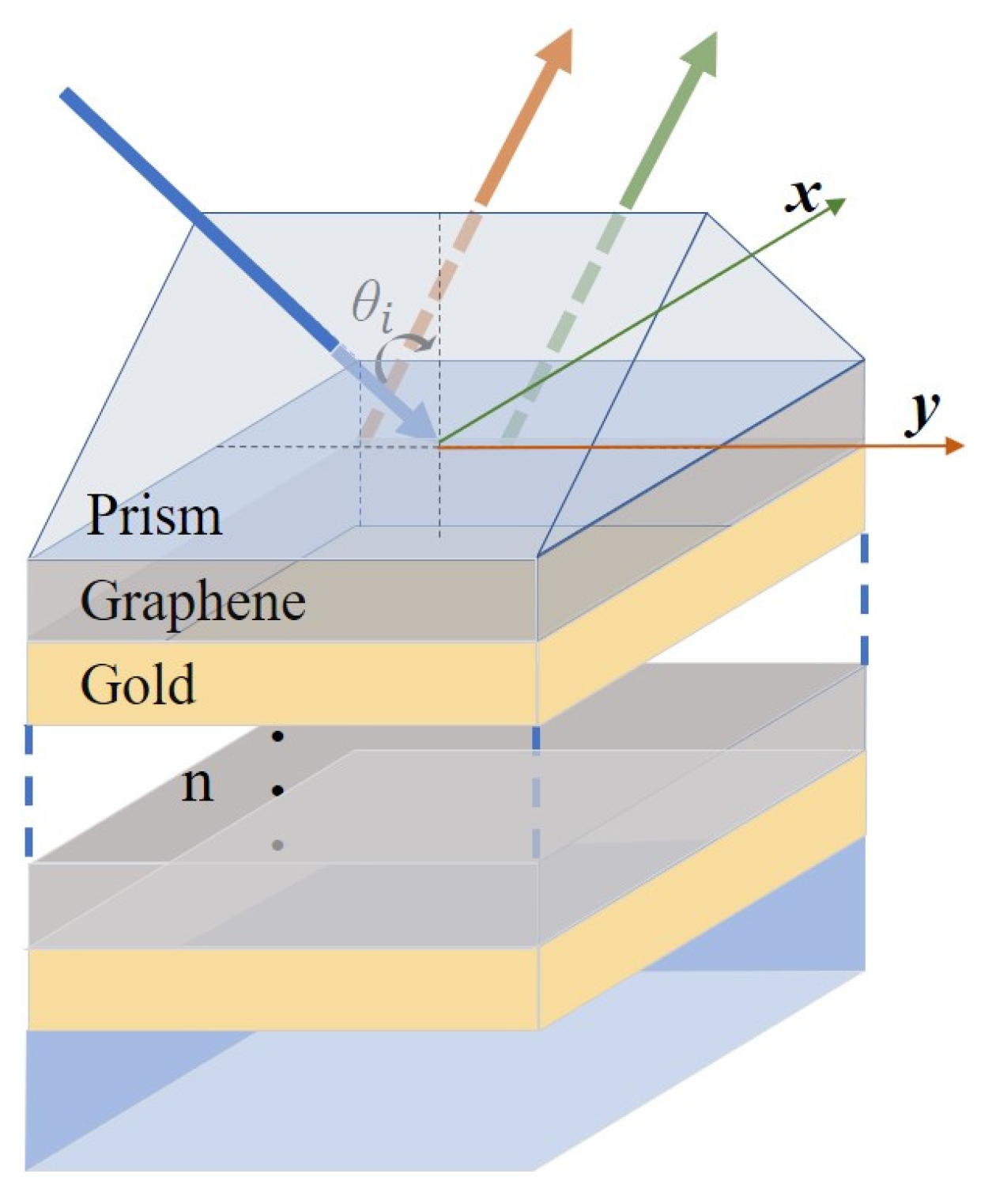
2. Materials and Methods

A linearly polarized Gaussian beam was coupled using a prism incident at θ angle from the graphene–gold layer structure and reflected at the dielectric interface, resulting in the spin Hall effect of light, and the splitting of the beam into LHCP and RHCP components, producing a SHEL shift in the y axis. Suppose the incident plane is the xoz plane, with an angular spectrum [6]:
E ˜ i ± ( k i x , k i y ) = ( e i x + i σ e i y ) w 0 2 π exp [ w 0 2 ( k i x 2 + k i y 2 ) 4 ]
where E ˜ i ± ( k i x , k i y ) represents the angular spectrum propagating in the z-axis direction, k i x and k i y are the x-axis component and y-axis component of the incident wave vector, with “+” and “−” corresponding to the left and right circularly polarized beam, respectively. The schematic diagram of the structure is shown in Figure 1.
The dielectric tensor matrix of graphene at terahertz frequencies can be obtained from the following [22]:
ε = [ ε x x ε x y 0 i ε y x ε y y 0 0 0 1 ]
where the effective dielectric constant diagonal and non-diagonal elements of graphene are defined by the following equations [23]:
ε x x = i σ x x ω ε 0 t g
and
ε x y = i σ x y ω ε 0 t g
where ω is the angular frequency of the incident beam, ε 0 is the vacuum dielectric constant, and t g is the thickness of single-layer graphene ( t g = 0.5 nm). The photoconductivity tensors of diagonal and non-diagonal elements of graphene are defined by the following equations:
σ x x = σ y y = e 2 E f π 2 i ( ω + i / τ ) ( i / τ + ω ) 2 ω c 2
and
σ x y = σ y x = e 2 E f π 2 ω c ( i / τ + ω ) 2 ω c 2
where E f is the effective Fermi level, = h / ( 2 π ) is the approximate Planck constant, τ is the relaxation time ( τ = 0.2 × 10 9 s ), e is the elementary charge ( e = 1.6 × 10 19 C ), ω c is the cyclotron frequency ( ω c = e v f 2 B / | E f | ), v f is Fermi velocity ( v f = 9.5 × 10 5 m/s). After determining the basic parameters, we calculated the reflection coefficients of the incident and reflected light in the multilayer dielectric film structure following the nonlinear magneto-optical transfer matrix method and then calculated the optical spin Hall effect displacement of the whole structure [24,25,26].
According to the nonlinear magneto-optical transfer matrix method, the dynamic matrix of elements is:
D ( 2 ) = [ D 11 D 12 D 13 D 14 D 21 D 22 D 23 D 24 D 31 D 32 D 33 D 34 D 41 D 42 D 43 D 44 ]
Depending on the magnetization vector or the direction of the applied magnetic field, as shown in Figure 2, the Kerr effect is divided into the longitudinal Kerr effect (LMOKE, θ M = π / 2 , ϕ M = 0 or π), transverse Kerr effect (TMOKE, θ M = π / 2 , ϕ M = 0 or π), and polar Kerr effect (PMOKE, θ M = 0 or π), corresponding to different values of each element in the dynamic matrix, where θ M and φ M are the zenith angle and azimuthal angle in the spherical coordinate, respectively. In TMOKE, D 11 = D 12 = 11 , D 21 = D 22 = N z 1 , D 33 = D 34 = ε z z N y 2 , D 43 = ( N y ε z y + N z 3 ε z z ) , D 44 = ( N y ε z y + N z 4 ε z z ) , others are zero. In PMOKE, D 1 j = D 11 = ε x y ( ε z z N y 2 ) , D 21 = D 22 = N z + D 11 , D 23 = D 24 = N z D 11 , D 31 = D 32 = ( ε z z N y 2 ) ( ε x x N y 2 N z + 2 ) , D 33 = D 34 = ( ε z z N y 2 ) ( ε x x N y 2 N z 2 ) , D 41 = D 42 = N z + ε z z ( ε x x N y 2 N z + 2 ) , D 43 = D 44 = N z ε z z ( ε x x N y 2 N z 2 ) in which N y = n sin θ .
In isotropic layers:
D ( 1 , 3 , 4 ) = [ 1 1 0 0 N z 0 ( n ) N z 0 ( n ) 0 0 0 0 N z 0 ( n ) ( ε 0 ( n ) ) 1 / 2 N z 0 ( n ) ( ε 0 ( n ) ) 1 / 2 0 0 ( ε 0 ( n ) ) 1 / 2 ( ε 0 ( n ) ) 1 / 2 ]
The propagation matrix of isotropic layers and magnetic layer is:
P ( n ) = [ exp ( i ω c N z 1 ( n ) d ( n ) ) 0 0 0 0 exp ( i ω c N z 2 ( n ) d ( n ) ) 0 0 0 0 exp ( i ω c N z 3 ( n ) d ( n ) ) 0 0 0 0 exp ( i ω c N z 4 ( n ) d ( n ) ) ]
in which d ( n ) is the thickness of nth layer. In the isotropic layers, N z j ( n ) = N z 0 ( n ) (j = 1, 2, 3, 4), N z 0 ( n ) = N ( n ) 2 N y 2 , and N ( n ) = μ ( n ) ε 0 ( n ) . In the MO layer, N z i (i = 1, 2, 3, 4) can be obtained by:
N z 1 , 3 ( n ) = N z 0 ( n ) ( 1 ε 1 ( n ) 2 / 4 ε 0 ( n ) N z 0 ( n ) 2 ) ± ε 1 ( n ) / 2 ε 0 ( n ) 1 / 2 N z 0 ( n ) / ( N z 0 ( n ) cos θ M ( n ) + N y sin θ M ( n ) sin ϕ M ( n ) ) + ε 1 ( n ) 2 / 8 ε 0 ( n ) N z 0 ( n ) 3 ( N z 0 ( n ) 2 cos 2 θ M ( n ) N y 2 sin θ M ( n ) 2 sin ϕ M ( n ) 2 )
N z 2 , 4 ( n ) = N z 0 ( n ) ( 1 ε 1 ( n ) 2 / 4 ε 0 ( n ) N z 0 ( n ) 2 ) ε 1 ( n ) / 2 ε 0 ( n ) 1 / 2 N z 0 ( n ) / ( N z 0 ( n ) cos θ M ( n ) N y sin θ M ( n ) sin ϕ M ( n ) ) ε 1 ( n ) 2 / 8 ε 0 ( n ) N z 0 ( n ) 3 ( N z 0 ( n ) 2 cos 2 θ M ( n ) N y 2 sin θ M ( n ) 2 sin ϕ M ( n ) 2 )
in which ε 0 ( n ) N y 2 = N z 0 ( n ) 2 , N y = n sin θ .
We performed a non-periodic structure simulation to calculate the total transmission matrix to obtain the reflection coefficient, combining the D matrix and P matrix of each layer. The total transmission matrix Q is:
Q = D ( 1 ) 1 D ( 2 ) P ( 2 ) D ( 2 ) 1 D ( 3 ) P ( 3 ) D ( 3 ) 1 D ( 4 )
in which matrix D ( n ) ( n = 1 , 2 , 3 ) and P ( n ) ( n = 2 , 3 ) are the dynamic matrix and transmission matrix of each layer, respectively.
The matrix Q contains all the information about the distribution of the incident and reflected light fields and allows calculation of the reflection coefficients of the multilayer structure:
r ss = Q 21 Q 33 Q 23 Q 31 Q 11 Q 33 Q 13 Q 31
r ps = Q 41 Q 33 Q 43 Q 31 Q 11 Q 33 Q 13 Q 31
r sp = Q 11 Q 23 Q 13 Q 21 Q 11 Q 33 Q 13 Q 31
r pp = Q 11 Q 43 Q 13 Q 41 Q 11 Q 33 Q 13 Q 31
in which for the reflection coefficient r i j (i, j = s or p), i indicates that the incident beam is s-polarized or p-polarized, and j indicates that the reflected beam is s-polarized or p-polarized.
By transforming the coordinates and applying each of the above parameters, the angular spectrum expressions of the reflected and incident light can be correlated as:
[ E ˜ r H E ˜ r V ] = [ r p p k r y k 0 ( r p s r s p ) cot θ i r p s k r y k 0 ( r p p r s s ) cot θ i r s p k r y k 0 ( r p p r s s ) r s s cot θ i r s s k r y k 0 ( r p s r s p ) cot θ i ] × [ E ˜ i H E ˜ i V ]
where H and V in the angular spectrum component of the reflected or incident beam represent horizontally polarized light (H-polarization) and vertically polarized light (V-polarization), respectively, k 0 denotes the wavenumber in the vacuum, k r y denotes the y-axis component of the wave vector of all reflected beams after transformation to the current coordinate system, θ i is the incident angle, r p and r s are the reflection coefficients of the multilayer structure, and their subscripts represent different polarization states (p for H and s for V), which can be obtained by the classical MO transfer matrix method. Combining the interconnection of linearly and circularly polarized light (linearly polarized light can be decomposed into a superposition of left- and right-handed circularly polarized components):
E ˜ r H = 1 2 ( E ˜ r + + E ˜ r )
E ˜ r V = 1 2 i ( E ˜ r + E ˜ r )
where E ˜ r + and E ˜ r denotes the left- and the right-handed circularly polarized light components of the angular spectrum, respectively. The expression of the electric field distribution of the reflected beam can be obtained by inverting the Fourier transform of the angular spectrum of the reflected beam:
E r ( x r , y r , z r ) = E ˜ r ( k r x , k r y ) exp [ i ( k r x x r + k r y y r + k r z z r ) ] d k r x d k r y
By integrating over the centroid, the transverse shift of the reflected light can be defined as:
δ ± = E r ± E r ± y d x d y E r ± E r ± d x d y
in which “+” and “−” correspond the LHCP and RHCP components, respectively.

3. Results and Discussion

In the following, we describe the simulation and comparison of the optical field transmission characteristics of the above structures in the visible and terahertz wavelengths under an applied magnetic field. The effect of an applied magnetic field on the photonic spin Hall effect of the designed structure was investigated in the presence of an applied transverse magnetic field and a polar magnetic field, respectively. The results show that the transverse and polar magnetic fields both affected the magnitude of the shift in the SHEL of the reflected beam. A single layer of graphene with a thickness of t g = 0.5 nm was utilized for the testing, with Au selected as the metal layer to analyze the effect of Au layer thickness on the beam shift, in order to obtain the optimal waveguide structure.

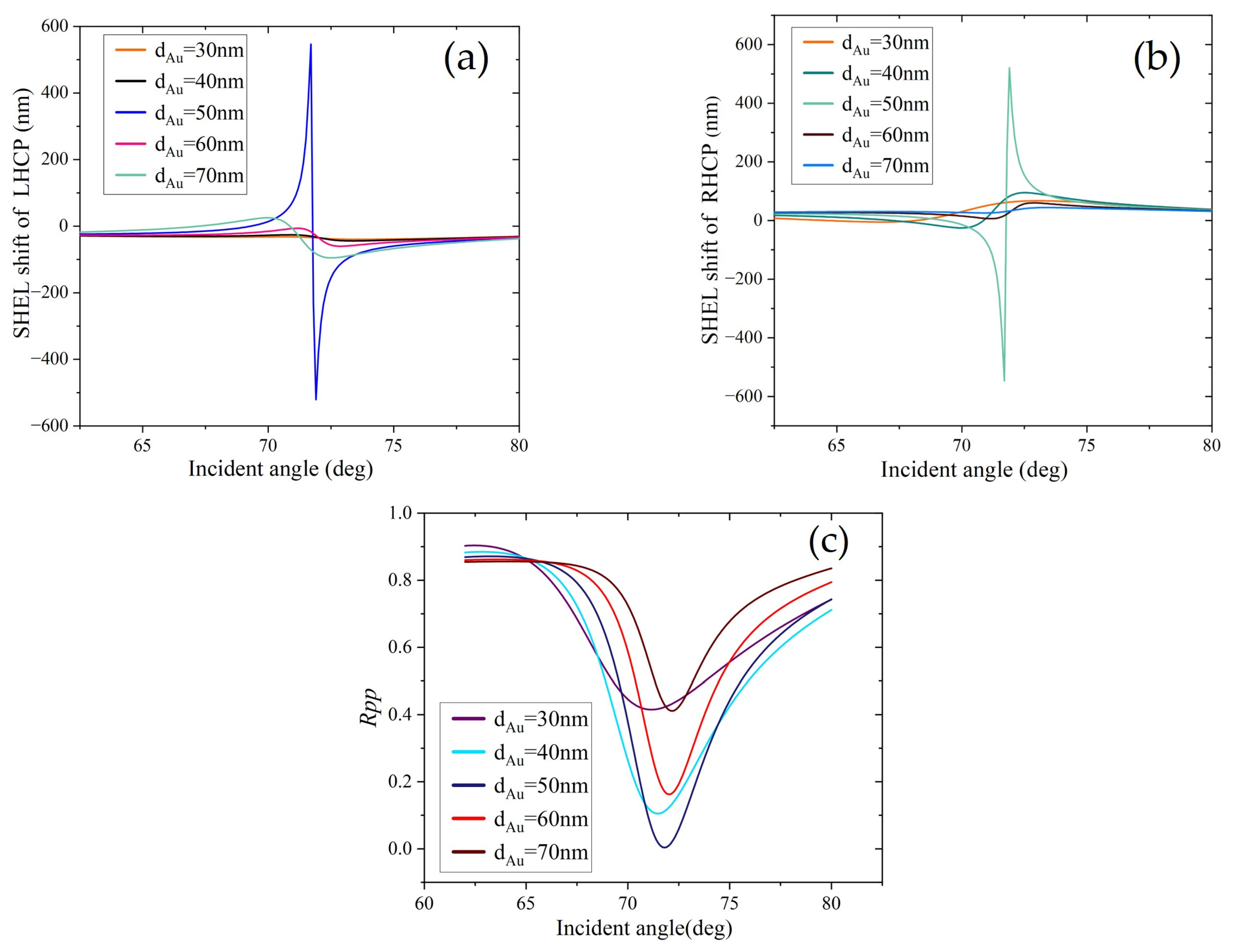
3.1. MOSHEL of Graphene–Gold Heterojunction Structure in Visible Light

The incident beam wavelength in PMOKE was 632.8 nm. Here we selected B = 10 T, E f = 0.2 eV, τ = 0.2 ps. As indicated in Figure 3a, when the thickness of the gold layer increased from 30 nm to 70 nm, the transverse shift of the left circularly polarized light increased and then decreased, reaching its maximum when the thickness was 50 nm. As the simulation curve of RHCP in Figure 3b is symmetrically distributed with the LHCP, the changing trend is similar to that shown in Figure 3a. Figure 3 therefore shows that when the thickness of the gold layer was 50 nm, the SHEL distribution of circularly polarized light was at its maximum value is 330 nm. The theoretical distribution of the reflection coefficient of the incident light is shown in Figure 3d, revealing that the reflection coefficient was at its minimum at an incidence angle of 72°, at which the reflection coefficient R approached 0 corresponding with the maximum value of the SHEL shift, consistent with the three preceding figures.
The direction of the applied magnetic field was changed to transverse (TMOKE), and the same structural parameters selected as were used for PMOKE. The curves of the SHEL shift with the incident angle for LHCP and RHCP are shown in Figure 4a,b. Similar to PMOKE, with the increase of the gold layer’s thickness, the SHEL shift showed an increasing and then decreasing trend. When the thickness of the gold layer was 50 nm, the SHEL shift was at its largest, reaching 546 nm, which was 1.65 times the maximum value under PMOKE. We selected the TMOKE mode for all subsequent simulations. The theoretical coefficient values of the incident light reflection and incident angle for different thicknesses of gold layer are shown in Figure 4c. The lowest values of reflection coefficient from 30 nm to 70 nm, respectively, were 0.41, 0.11, 0.002, 0.16, and 0.42. At Au layer thickness of 50 nm, the curve of the theoretical value of the reflection coefficient had its lowest minimum value (near 72°), and the R tended towards 0, corresponding to the SHEL peak.

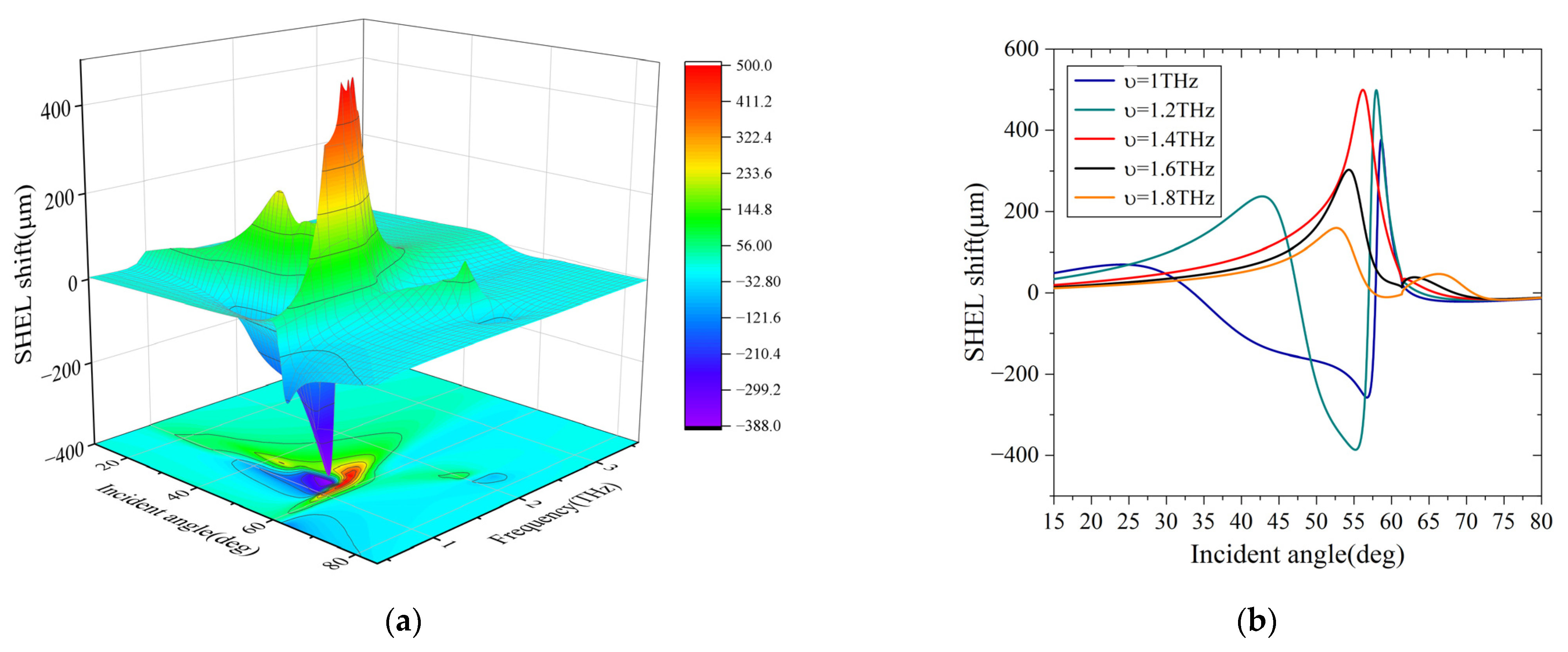
3.2. MOSHEL of Graphene–Gold Heterojunction Structure at Terahertz Wavelengths

This study investigated the optical spin Hall effect in a prism-coupled graphene–metal metamaterial waveguide structure (with a SiO2 substrate) at terahertz wavelengths. Here we selected E f = 0.2 eV, τ = 0.2 ps, B = 10 T. Because of its high magnetic field response, graphene exhibits a large magneto-optical effect in the terahertz band. Calculations showed that the splitting value of SHEL jumped from the nanometer to the micron scale, and as shown in the color intensity plot of SHEL with incident angle and terahertz frequency in Figure 5a, the peak was close to 500 μm, a 1000-fold increase compared to that at visible wavelengths. According to its intensity projection map in the xoy plane, the peak region for SHEL was in the incident angle range of 55–60°, the frequency of the incident terahertz waves in the range 0.8–1.8 THz, and its transverse shift was prominent. When the incidence angle was about 58°, they all exhibited large amplitude distribution. As shown in Figure 5b, the variation curve of the SHEL shift with the incident angle was irregular at different terahertz frequencies, and with the increase of frequency f, the splitting value of SHEL showed an increase and then a decrease, and the maximum splitting value of SHEL reached 498 μm at a frequency of 1.2 THz.
We investigated the effect of an applied magnetic field on the magneto-optical effect of graphene under terahertz waves by varying the applied magnetic induction strength. In Figure 6, the magnitude of the magnetic induction intensity exerts different effects on the shift of SHEL for different Fermi energy levels of graphene. With the increase of E f , the extreme value of SHEL increased and then decreased. The SHEL shift was close to 500 µm when E f = 0.2 eV. Furthermore, when E f was a constant value, as in Figure 6a, the SHEL shift decreased gradually as the magnetic induction density B increased when E f = 0.1 eV. When E f increased, as shown in Figure 6b–d, the SHEL presented an irregular distribution with magnetic induction density. Meanwhile, with the increase of B, the asymmetry distribution of SHEL was more obvious and the gap between positive and negative extreme values increased. This phenomenon is largely because the non-diagonal element varies when B increases, resulting in variation of the Faraday rotation angle and the SHEL peak value. Meanwhile, the spin shift of SHEL is related to the ratio of the Fennel reflection coefficient, and the ratio changes under different magnetic induction intensity so the angular spectrum distribution changes accordingly.

3.3. MOSHEL of Graphene–Gold n-Layer Periodic Structure at Terahertz Wavelengths

From the above discussion, we were able to define the specific parameters dAu = 50 nm, B = 10 T, E f = 0.2 eV, v = 1.2 THz, τ = 0.2 ps, to explore the effect of periodic graphene–gold structure on the transverse split of the optical spin Hall effect within this system. Graphene alternates periodically with gold layers to form a metamaterial, essentially an artificial structure with dimensions much larger than conventional atoms and much smaller than the wavelength of incident light, thus giving it the desired optical properties to generate new capacity to manipulate light waves. A schematic diagram of the periodic structure is shown in Figure 7. In combination with the D and P matrices of each layer in the periodic structure, the Q matrix connecting the electric field amplitudes of the incident and reflected light is:
Q = D ( 1 ) 1 [ D ( 2 ) P ( 2 ) D ( 2 ) 1 D ( 3 ) P ( 3 ) D ( 3 ) 1 ] n D ( 4 )
in which n denotes the periodic numbers of graphene and Au layers.
We simulated structures with different numbers of layers, and the simulations of the SHEL shifts of the LHCP and RHCP components with the incident angles are shown in Figure 8. The maximum values of the SHEL shifts were 498 μm, 218 μm, 276 μm, and 80.5 μm at the period numbers 1, 3, 7 and 11, respectively, showing an oscillating trend from decreasing to increasing and finally decreasing again.
The simulation curve of the SHEL shift with the incident angle at different terahertz frequencies for the period n = 7 is shown in Figure 9a, for which the maximum value of the SHEL shift was near the incident angle of 61°, corresponding to a terahertz frequency v = 1.2 THz. This is consistent with the results discussed above. From the variation curve of the SHEL shift and the number of periods shown in Figure 9b, it can be seen that as the number of periods n increases, the overall SHEL value decreased, with a smaller change at n = 7. It can be concluded that, under this structure, when the period number n is less than or equal to 10, the value of the SHEL shift oscillates with the increase of the period number. In contrast, when n exceeds 10, the value of the SHEL shift gradually decreases. This is because although the anisotropy of the multilayer periodic metamaterial structure significantly increases the transverse splitting of the left- and right-handed circularly polarized light, the multi-stroke absorption of light between the layers increases with the increase of the skinning depth, leading to a step-by-step decrease of the SHEL effect, and thus also the splitting value of its beam, but remaining in the order of μm.

4. Conclusions

For the first time, the transverse splitting of the optical spin Hall effect in a prism-coupled graphene–gold structure has been studied and calculated at terahertz frequencies by introducing a nonlinear magneto-optical transfer matrix method. The magnetic field size was found to affect the size of the optical spin Hall effect splitting of the reflected beam, whether an applied transverse magnetic field or polar magnetic field was used. Based on derivation of the theory and discussion of the simulation results, we analyzed the effects of the thickness of the gold layer, the Fermi energy level of the graphene, the terahertz wave frequency, and the period number of the graphene–gold layer structure on the SHEL displacement distributions of the LHCP and RHCP components. The results showed that when the thickness of the gold layer was 50 nm, the Fermi energy level 0.2 eV, and the terahertz frequency 1.2 THz, the maximum spin splitting value of SHEL was 498 μm, 1000 times higher than that in the visible wavelength band. Although the anisotropy of the multilayer periodic metamaterial structure significantly increased the transverse splitting of the left- and right-handed circularly polarized light, the multiple absorptions of light between the layers increased with the increase of skinning depth, leading to a step-by-step decrease in the SHEL effect. Thus, the splitting value of the beam also decreased, but remained in the order of μm. Due to the magneto-optical properties of graphene, it is possible to modulate the SHEL shift by changing the magnitude and direction of the applied magnetic field. This structure will provide the possibility of enhancing the transverse shift and effectively regulating the optical spin Hall effect in the terahertz band.

Author Contributions

Conceptualization, L.L.; methodology, L.L.; software, J.G. and L.L.; validation, J.G., X.L., and Y.W.; investigation, J.G.; resources, S.P. and B.L.; writing—original draft preparation, J.G.; writing—review and editing, L.L., J.G., and Y.W.; supervision, L.L., S.P., and B.L.; project administration, L.L.; funding acquisition, L.L. All authors have read and agreed to the published version of the manuscript.

Funding

This research was funded by the National Natural Science Foundation of China (Grant Nos. 11904038); the Key Research and Development Project of Sichuan Province: Research on Development and Application Technology of VO2 Nano powder/Slurry with Intelligent Temperature Control (Subproject Nos. 2022Z091).

Institutional Review Board Statement

Not applicable.

Informed Consent Statement

Not applicable.

Data Availability Statement

Not applicable.

Conflicts of Interest

The authors declare that they have no known competing financial interests or personal relationships that could have appeared to influence the work reported in this paper.

References

  1. Onoda, M.; Murakami, S.; Nagaosa, N. Hall effect of light. Phys. Rev. Lett. 2004, 93, 083901. [Google Scholar] [CrossRef] [PubMed] [Green Version]
  2. Bliokh, K.Y.; Bliokh, Y.P. Conservation of angular momentum, transverse shift, and spin Hall effect in reflection and refraction of an electromagnetic wave packet. Phys. Rev. Lett. 2006, 96, 073903. [Google Scholar] [CrossRef] [PubMed] [Green Version]
  3. Bliokh, K.Y.; Niv, A.; Kleiner, V.; Hasman, E. Geometrodynamics of spinning light. Nat. Photonics 2008, 2, 748–753. [Google Scholar] [CrossRef] [Green Version]
  4. Hosten, O.; Kwiat, P. Observation of the spin Hall effect of light via weak measurements. Science 2008, 319, 787–790. [Google Scholar] [CrossRef] [PubMed] [Green Version]
  5. Qin, Y.; Li, Y.; He, H.Y.; Gong, Q.H. Measurement of spin Hall effect of reflected light. Opt. Lett. 2009, 34, 2551–2553. [Google Scholar] [CrossRef] [PubMed]
  6. Luo, H.L.; Zhou, X.X.; Shu, W.X.; Wen, S.C.; Fan, D.Y. Enhanced and switchable spin Hall effect of light near the Brewster angle on reflection. Phys. Rev. A 2011, 84, 043806. [Google Scholar] [CrossRef] [Green Version]
  7. Qiu, X.D.; Zhang, Z.Y.; Xie, L.G.; Qiu, J.D.; Gao, F.H.; Du, J.L. Incident-polarization-sensitive and large in-plane-photonic-spin-splitting at the Brewster angle. Opt. Lett. 2015, 40, 1018–1021. [Google Scholar] [CrossRef]
  8. Tang, T.T.; Li, J.; Zhang, Y.F.; Li, C.Y.; Luo, L. Spin Hall effect of transmitted light in a three-layer waveguide with lossy epsilon-near-zero metamaterial. Opt. Express 2016, 24, 28113–28121. [Google Scholar] [CrossRef]
  9. Tang, T.T.; Li, J.; Luo, L.; Sun, P.; Zhang, Y.F. Loss enhanced spin Hall effect of transmitted light through anisotropic epsilon-and mu-near-zero metamaterial slab. Opt. Express 2017, 25, 2347–2354. [Google Scholar] [CrossRef]
  10. Coutaz, J.L.; Garet, F.; Wallace, V. Principles of Terahertz Time-Domain Spectroscopy, 1st ed.; CRC Press: New York, NY, USA, 2018. [Google Scholar]
  11. Dexheimer, S.L. Terahertz Spectroscopy: Principles and Application, 1st ed.; CRC Press: Boca Raton, FL, America, 2017. [Google Scholar]
  12. Berger, C.; Song, Z.; Li, X.B.; Wu, X.S.; Brown, N.; Naud, C.; Mayou, D.; Li, T.B.; Hass, J.; Marchenkov, A.N.; et al. Electronic confinement and coherence in patterned epitaxial graphene. Science 2006, 312, 1191–1196. [Google Scholar] [CrossRef]
  13. Luo, L.; Feng, G.Y.; Zhou, S.H.; Tang, T.T. Photonic spin Hall effect of reflected light in a prism-graphene waveguide. Superlattices Microstruct. 2018, 122, 530–537. [Google Scholar] [CrossRef]
  14. Wang, L.; Wu, B.; Chen, J.; Liu, H.; Hu, P.; Liu, Y. Monolayer hexagonal boron nitride films with large domain size and clean interface for enhancing the mobility of graphene-based field-effect transistors. Adv. Mater. 2014, 26, 1559–1564. [Google Scholar] [CrossRef] [PubMed]
  15. Li, J.; Tang, T.T.; Luo, L.; Li, N.X.; Zhang, P.Y. Spin Hall effect of reflected light in dielectric magneto-optical thin film with a double-negative metamaterial substrate. Opt. Express 2017, 25, 19117–19128. [Google Scholar] [CrossRef] [PubMed]
  16. Li, J.; Tang, T.T.; Luo, L.; Yao, J.Q. Enhancement and modulation of photonic spin Hall effect by defect modes in photonic crystals with graphene. Carbon 2018, 134, 293–300. [Google Scholar] [CrossRef] [Green Version]
  17. Kaihara, T.; Ando, T.; Shimizu, H.; Zayets, V.; Saito, H.; Ando, K.; Yuasa, S. Enhancement of magneto-optical Kerr effect by surface plasmons in trilayer structure consisting of double-layer dielectrics and ferromagnetic metal. Opt. Express 2015, 23, 11537–11555. [Google Scholar] [CrossRef]
  18. Wang, Q.; Jiang, X.; Wang, X.; Dai, X.; Xiang, Y. Enhancing photonic spin Hall effect in the surface plasmon resonance structure covered by the graphene–MoS2 heterostructure. IEEE Photonics J. 2017, 9, 1–10. [Google Scholar] [CrossRef]
  19. Nagaosa, N.; Sinova, J.; Onoda, S.; MacDonald, A.H.; Ong, N.P. Anomalous Hall effect. Rev. Mod. Phys. 2010, 82, 1539. [Google Scholar] [CrossRef] [Green Version]
  20. Berger, L. Side-jump mechanism for the Hall effect of ferromagnets. Phys. Rev. B 1970, 2, 4559. [Google Scholar] [CrossRef]
  21. Smit, J. The spontaneous hall effect in ferromagnetics II. Physica 1958, 24, 39–51. [Google Scholar] [CrossRef]
  22. Tymchenko, M.; Nikitin, A.Y.; Martin-Moreno, L. Faraday rotation due to excitation of magnetoplasmons in graphene microribbons. ACS Nano 2013, 7, 9780–9787. [Google Scholar] [CrossRef]
  23. Gusynin, V.P.; Sharapov, S.G.; Carbotte, J.P. Magneto-optical conductivity in graphene. J. Phys. Condens. Matter 2006, 19, 026222. [Google Scholar] [CrossRef] [Green Version]
  24. Višňovský, Š. Magneto-optical ellipsometry. Czechoslov. J. Phys. B 1986, 36, 625–650. [Google Scholar] [CrossRef]
  25. Višňovský, Š.; Lopušník, R.; Bauer, M.; Bok, J.; Fassbender, J.; Hillebrands, B. Magnetooptic ellipsometry in multilayers at arbitrary magnetization. Opt. Express 2001, 9, 121–135. [Google Scholar] [CrossRef] [PubMed]
  26. Schubert, M. Infrared Ellipsometry on Semiconductor Layer Structures: Phonons, Plasmons, and Polaritons; Springer Science & Business Media: Berlin/Heidelberg, Germany, 2005. [Google Scholar]
Figure 1. Schematic of prism-coupled monolayer graphene–gold structure and representation of SHEL shift.
Crystals 13 00078 g001
Figure 2. Schematic diagram of the magneto-optical Kerr effect in three different directions.
Crystals 13 00078 g002
Figure 3. (a) Variation of SHEL shift of LHCP component with the incident angle at different thicknesses of gold layer; (b) variation of SHEL shift of RHCP component with the incident angle at different thicknesses of gold layer; (c) variation of SHEL shift versus incident angle when the thickness of gold layer was 50 nm; (d) Variation of reflection coefficient R versus incident angle when the thickness of gold layer was 50 nm.
Crystals 13 00078 g003
Figure 4. (a) Variation of SHEL shift of LHCP component with the incident angle, at different thickness of gold layer; (b) variation of SHEL shift of RHCP component with the incident angle, at different thickness of gold layer; (c) variation of reflection coefficient R with the incident angle, at different thickness of gold layer.
Crystals 13 00078 g004
Figure 5. (a) Three-dimensional distribution of the beam centroid displacement of SHEL with the incident angle at different frequencies; (b) variation of SHEL shift with the incident angle at different frequencies.
Crystals 13 00078 g005
Figure 6. At different Fermi levels ( E f ), variation of the beam centroid displacement of SHEL at different magnetic induction densities with the incident angle (a) E f = 0.1 eV; (b) E f = 0.2 eV; (c) E f = 0.3 eV; (d) E f = 0.4 eV.
Crystals 13 00078 g006aCrystals 13 00078 g006b
Figure 7. Schematic diagram of n-layer periodic structure.
Crystals 13 00078 g007
Figure 8. Variation of SHEL shift with incident light at different periods (n). (a) n = 1 (b) n = 3 (c) n = 7 (d) n = 11.
Crystals 13 00078 g008
Figure 9. (a) Three-dimensional distribution of the beam centroid displacement of SHEL at different frequencies with the incident angle, when the number of periods was seven; (b) SHEL shift versus number of periods.
Crystals 13 00078 g009
Disclaimer/Publisher’s Note: The statements, opinions and data contained in all publications are solely those of the individual author(s) and contributor(s) and not of MDPI and/or the editor(s). MDPI and/or the editor(s) disclaim responsibility for any injury to people or property resulting from any ideas, methods, instructions or products referred to in the content.

