Article

Characterization and Gamma-ray Shielding Performance of Calcinated and Ball-Milled Calcinated Bentonite Clay Nanoparticles

by
Fawzy H. Sallem
1,
M. I. Sayyed
2,*,
Dalal Abdullah Aloraini
3,
Aljawhara H. Almuqrin
3 and
K. A. Mahmoud
1,4
1
Nuclear Materials Authority, El-Maadi, Cairo P.O. Box 530, Egypt
2
Department of Physics, Faculty of Science, Isra University, Amman 11622, Jordan
3
Department of Physics, College of Science, Princess Nourah bint Abdulrahman University, P.O. Box 84428, Riyadh 11671, Saudi Arabia
4
Department of Nuclear Power Plants and Renewable Energy, Ural Energy Institute, Ural Federal University, 19 Mira St., 620002 Yekaterinburg, Russia
*
Author to whom correspondence should be addressed.
Crystals 2022, 12(8), 1178; https://doi.org/10.3390/cryst12081178
Submission received: 12 July 2022 / Revised: 18 August 2022 / Accepted: 19 August 2022 / Published: 22 August 2022
(This article belongs to the Section Mineralogical Crystallography and Biomineralization)

Abstract

:
The current investigation deals with the fabrication of two various composite-based bentonite clay minerals. The characterization and radiation shielding parameters for the two fabricated composites (calcinated and ball-milled calcinated bentonite) were studied. X-ray diffraction was utilized to illustrate the crystalline phase of the fabricated composites. Furthermore, Williamson and Hall’s method was used to determine the grain size of both the calcinated and ball-milled calcinated composites. The particle size, according to the calculation was 39.84 nm, and the strain was 0.216 for the calcinated bentonite, while the particle size of the ball-milled bentonite was 26.96 nm, and the strain was 0.219. In comparison, the transmission electron microscope (TEM) showed that the grain size of the calcinated bentonite was 566.59 nm, and it was 296.21 nm for the ball-milled calcinated bentonite. The density of the fabricated composites varied between 1.60 and 186 g/cm3 for the calcinated bentonite and between 1.83 and 2.075 g/cm3 for the ball-milled calcinated bentonite. Moreover, the radiation shielding capacity of the composites was analyzed. The results show that the gamma-ray attenuation capacity of ball-milled calcinated bentonite is high compared to ordinary calcinated bentonite. These results confirm the effect of particle grain size on optimizing the gamma-ray shielding capacity of the fabricated materials.

1. Introduction

Gamma-rays, as well as other high-energy radiation such as X-rays, can easily penetrate the human body. In the case of X-rays, this ability can be extremely useful in radiology, but exposure to certain doses of radiation may result in permanent cell damage and acute radiation poisoning and has previously been demonstrated to lead to serious health issues such as cancer. To mitigate these harmful effects, researchers have developed radiation shields, which are materials placed between humans and the radiation source that are used to absorb as many of the outgoing high-energy photons as possible, lowering the levels of exposure to an acceptable amount [1].
To measure how well a material acts as a radiation shield, various attenuation coefficients are calculated, usually at several energies and sometimes different thicknesses, to assess the viability of the material being tested for radiation shielding applications. The shielding capability of material can depend on factors such as its composition and density, which is why researchers have used the mass attenuation coefficient of materials as the main indicator for its absorption ability, which is a parameter that factors in the density of a material. However, since different materials may be best suited for different applications, other parameters are also determined to view the material’s potential comprehensively.
Over the past several decades, materials such as composites, glasses, polymers, metals, concretes, alloys, and more have been extensively tested for their radiation shielding capabilities. Concrete, for instance, is often chosen because of its great shielding ability, low cost, range of composition, and ease of manufacturing. However, its tendency to crack and lose water over time has over the past several years created a concern for researchers who have sought to improve on these properties. In addition to concrete, ceramic and ceramic composite materials have recently gained popularity due to their mechanical strength, resistance to corrosion, low density, and high thermal durability. This interest has led to the investigation of bentonite as a candidate for shielding applications [2,3,4].
Bentonite is a type of clay mostly composed of the mineral montmorillonite. Bentonite can contain other minerals such as feldspar, quartz, illite, smectite, kaolinite, chlorite, and calcite. Bentonite is widely used because of its small crystal size, sheet-like structure, great surface area, and strong affinity for water. There exist two types of bentonite commonly used in industry: natural bentonite and sodium and calcium bentonite with each having some benefits over the other. This clay is used as an ingredient in metal casting, pet-waste absorbents, iron ore palletization, bleaching and clarifying in paper making, and much more. Bentonite is a good candidate for radiation shielding due to its desirable thermal features like good thermo-chemical stability and high corrosion resistance. In addition to bentonite being abundant around the world, these properties make it a great candidate for radiation shielding purposes [5,6,7,8].
Previous research has evaluated the shielding capability of natural bentonite and has found desirable results after some clay processing [5,6,7,8]. Furthermore, researchers have enhanced bentonite materials using cement, finding that the inclusion of concrete led to improvements in the shielding capability of the materials. Meanwhile, Sallam et al. focused on the effect of coating bentonite clay nanoparticles with a polyvinyl alcohol polymer and evaluating its attenuation capabilities against gamma-rays [9].
The present work’s novelty lies in fabricating the two various composites based on calcinated bentonite. The first composite was fabricated from calcinated bentonite at varying pressure rates between 50.98 and 152.95 Kg/cm2. The grain size of calcinated bentonite was reduced using the ball-milling method for the second composite. Subsequently, the second composite was fabricated under the same pressure as the first composite. The characterization and the shielding parameters for both composites were examined carefully.

2. Materials and Methods

2.1. Sample Fabrication

Bentonite is a clay rock deposit composed of crystalline clay-like minerals formed by the alteration of glassy igneous materials, either volcanic ash or tuff. The collection of the bentonite clay samples was carried out in the El-Mutalla Mountain area in southwestern Sinai, Egypt. For three hours, the collected bentonite samples were grounded (Fritsch Pulverisette, model 02.102) after being crushed with a hammer. Next, the samples were calcinated at a temperature of 700 °C for two hours to get rid of the water content from the inner bentonite crystals as well as to complete dehydration and dihydroxylation of the grained bentonite. The crushed and burned samples were taken and pressed into cylindrically shaped pellets with a diameter of 2 cm and different thicknesses. The samples were fabricated under pressure rates of 50.98, 101.97, and 152.95 kg/cm2. The second series of fabricated materials was produced by decreasing the calcinated bentonite grain sizes using the ball-milled method using a high-energy Retsch planetary ball mill PM 400 for four hours. The ball-milled powder was also pressed into cylindrically shaped pellets with a diameter of 2 cm and under various pressure rates varied between 50.98, 101.97, and 152.95 kg/cm2. All samples (calcinated and ball-milled) were coated with polyvinyl alcohol polymer (PVA).

2.2. Characterization

2.2.1. Chemical Composition

The fabricated materials’ thermal treatment (calcination processes) affects the natural bentonite structure, mineral oxide percentage, physicochemical properties, and water content. Regarding the thermal treatment, the dehydration of the bentonite was completed under a temperature range of between 500 and 700 °C. Besides, the OH group was dehydroxylated [10]. Due to the calcination process, the bentonite clay’s moisture and organic substance (loss of ignition, LOI) decreased from 30.34% to 8.67%. Furthermore, the percentage of silicon oxide decreased from 30% to 29.6%, while aluminum oxide and calcium oxide increased from 13.5% and 15.2% to 13.7% and 34.2%. In addition, the reactivity of aluminosilicate can be observed after calcination between 700 °C and 900 °C, while crystallization begins above 900 °C [11,12]. Calcinated bentonite contains miscellaneous mineral oxides, as shown in Table 1. The chemical composition of calcinated bentonite was evaluated using UV-Vis-NIR Spectroscopy (Shimazu UV-2401 dual beam) (Shimazu, Germany).

2.2.2. X-ray Diffraction Analysis

The XRD pattern was performed using the Malvern Panalytical Empyrean Diffractometer (K-Alpha = 1.54060, K-Alpha = 1.54443, and K-Beta = 1.39225) (Netherlands). The generator was set into 30 mA and 40 kv. The reflection peaks were between 2θ = 5° and 80°. The corresponding spacing (d, Å) and relative intensities were obtained. The XRD pattern for both samples is shown in Figure 1.

2.2.3. Particle Size Measurements

The size and strain of the bentonite samples can be determined using Williamson and Hall’s method based on XRD peak analysis. Crystallite size and lattice strain shift the 2θ peak position and increase peak width and intensity. Although the strain varies as tan θ also varies, the crystallite size varies as 1/cos θ varies from peak width. Williamson–Hall (W–H) analysis is an integral breadth method in which size and strain-induced increase peak width as a function of 2θ [13,14]. Using XRD patterns and the XPowder program [15], the particle size of the samples was obtained as illustrated in Figure 2.
Total broadening is equal to broadening due to the crystallites size and broadening due to strain as follows:
β t = β D + β
where βt is the total broadening of the peak, βD is the broadening due to the crystallites size, and β is the broadening due to strain.
From Debye-Scherer’s formula, the average crystallite size is calculated by the relation:
D = K   λ β D   Cos   θ
In the above equation, βD is the full width at half-maxima (FWHM) in radians. Similarly, the XRD broadening due to strain is given by:
β = 4   tan θ
where β is the broadening due to strain, is the strain and θ is the peak position in radians.
Putting Equations (2) and (3) in (1):
β T   Cos θ = K   λ D + 4     Sin θ
The Williamson–Hall equation defines as in Equation (4). Equation (4) represents the equation of a straight line, in which is the gradient (slope) of the line and Kd/D is the y-intercept value from which we can calculate the crystallite size D [16].

2.2.4. The Fabricated Samples Measurements

Material density is important for radiation shielding capacity examinations. The mentioned method is considered the best for measuring the density of small objects. Furthermore, in the mentioned method, the immersion liquid was xylene, where the weight of the bentonite samples in the air and in the immersion liquid was determined. Subsequently, the density of the bentonite sample was determined using the equation:
ρ sample = ρ liquid   ×   m air m air     m liquid

2.3. Radiation Shielding Evaluation

The Monte Carlo simulation code MCNP-5 was utilized to estimate the track length (ATL) of gamma photons inside the ball-milled and calcinated samples [17]. The estimated track length was used to evaluate the LAC for calcinated and ball-milled bentonite at 0.662, 1.173, and 1.332 MeV. The input file and geometry required to perform such a simulation has been discussed in detail in many previous papers [18,19,20].

3. Results and Discussion

3.1. X-ray Diffraction

The XRD patterns show that the calcinated bentonite sample has two crystalline phases which are calcite (calcium carbonate (CaCo3), JCPDS card No. 01-072-1937) and quartz (Silicon oxide (SiO2), JCPDS card No. 01-075-4408), while the ball-milled bentonite sample has three phases which are calcite (calcium carbonate (CaCo3), JCPDS card No. 01-083-4621), quartz (Silicon oxide (SiO2), JCPDS card No. 01-089-8937), and Hematite (Iron oxide (Fe2O3), JCPDS card No. 00-013-0534). Characteristic XRD peaks identify minerals in the calcinated and ball-milled bentonite clay. In the calcinated bentonite curve, the characteristic peaks for the calcite mineral found at 2Ɵ for L170-L182 are 29.36°, 36°, 39.4°, 43.19°, 47.48°, 48.5°, and 56.59°, while the characteristic peaks for quartz found at 2Ɵ are 26.59°, 29.36°, 33.02°, 39.4°, 47.48°, and 56.59°. Similarly, for the ball-milled bentonite, the characteristic peaks for the calcite mineral found at 2Ɵ are 22.91°, 29.28°, 31.15°, 35.89°, 39.33°, 43.09°, 47.4°, 48.4°, and 57.33°, while the characteristic peaks for quartz found at 2Ɵ are 26.5°, 35.89°, 39.33 °, and 57.33°; in addition to the characteristic peaks for the hematite mineral found at 2Ɵ are 35.89°, 39.33°, and 57.33°.
Both current samples have the same intense peak positions, especially at 2Ɵ and are 26.5°, 29.3°, 36°, 39.4°, and 47.4°, while the small rest peaks have a little shift due to deformation resulting from the ball milling. In addition, there is an agreement between the diffraction peaks and previous study results reported in the literature [21,22,23].
There are two dominant phases in both samples: calcite (CaCO3) which has a rhombohedral crystal structure, and quartz (SiO2) which has a hexagonal crystal structure.
Rhombohedral calcite crystal structure has unit cell lattice constants a = b ≠ c where a = b = 4.989 Å and c = 17.062 Å (for L 182), while the angel between lattice constants α = β ≠ γ where α = β = 90° and γ = 120° (for L 186 and L 187).
Similarly, the hexagonal quartz crystal structure has unit cell lattice constant a = b ≠ c where a = b = 4.9134 Å and c = 5.4052 Å, in addition to the angel between lattice constant α = β ≠ γ (α = β = 90 and γ = 120).

3.2. Particle Size Determination

According to the earlier illustrated Equations (1)–(4), the particle size was calculated using the XPowder program. The particle size of the calcinated bentonite is 39.84 nm, and the strain is 0.216, while the particle size of the ball-milled bentonite is 26.96 nm and a strain of 0.219. The notable decrease in particle size and increase in strain for the ball-milled bentonite is attributed to high energy Retsch planetary ball mill PM 400 mortar which reasons for size reduction.
The TEM was utilized in the present work to describe the morphology of the samples. The TEM allows precise measurements of the samples’ geometric characteristics. It is a reliable nanoparticle size distribution analysis. Figure 3 shows the morphology of the bentonite samples. It shows that both types of samples exhibit uniform spherical particle size. Furthermore, the particle size of the calcinated bentonite is 566.59 nm.
In comparison, the ball-milled bentonite is 296.21 nm, which highlights the effectiveness of the ball-milling process in decreasing particle size. In comparison with particle size obtained by W–H size analysis, the difference in particle size values explains that there is a large particle size distribution in the bentonite samples as it is a natural material formed from volcanic ash and increased by the calcination process (as temperature increases, particle size increases), and the degree of crystallinity is 75.5% obtained by the origin program. In addition, that difference in particle size values may be due to the strain induced in the sample structure.

3.3. Density Measurement

The variation in the density of the fabricated materials was illustrated versus the pressure rate (kg/cm2), as described in Figure 4. The samples treated with ball milling have increased density values between 1.83 and 2.075 g/cm3. Simultaneously, the density of the calcinated samples varied between 1.6 and 1.86 g/cm3 when raising the pressure rate between 50.986 and 152.957 kg/cm2. The results showed that at the same pressure rate, the enhancement in the density with the ball-milling method is better than that recorded for the calcinated samples. This may be related to the grain size of the bentonite clay mineral in both methods, where the bentonite grain size produced from the ball-milling method is smaller than the bentonite used in the calcination method. Thus, increasing the pressure rate causes a significant decrease in the distance between bentonite particles with the ball-milling method (due to the nanoscale of the bentonite particles), which produces more compact and dense tablets than those produced in the calcinated bentonite.

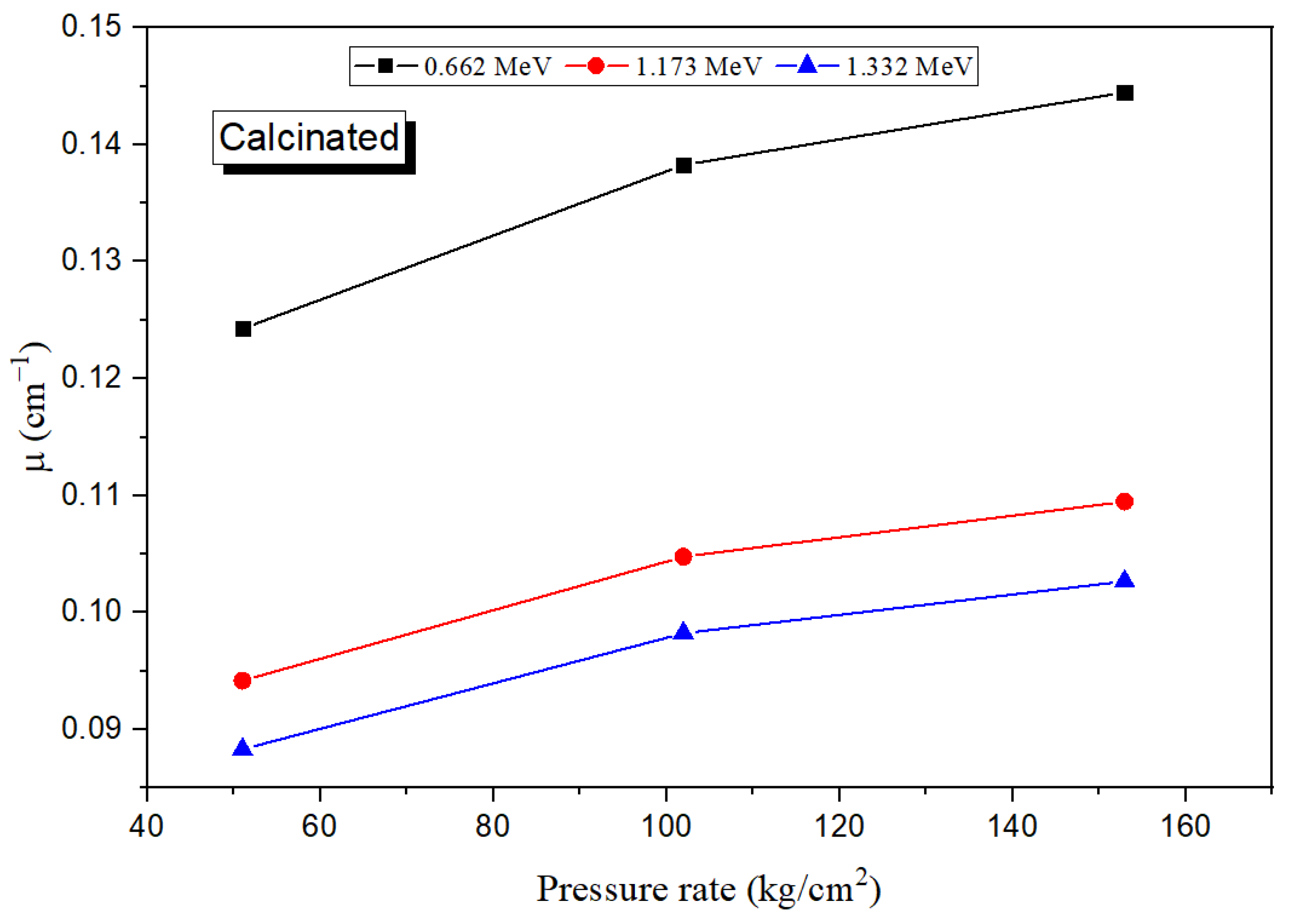
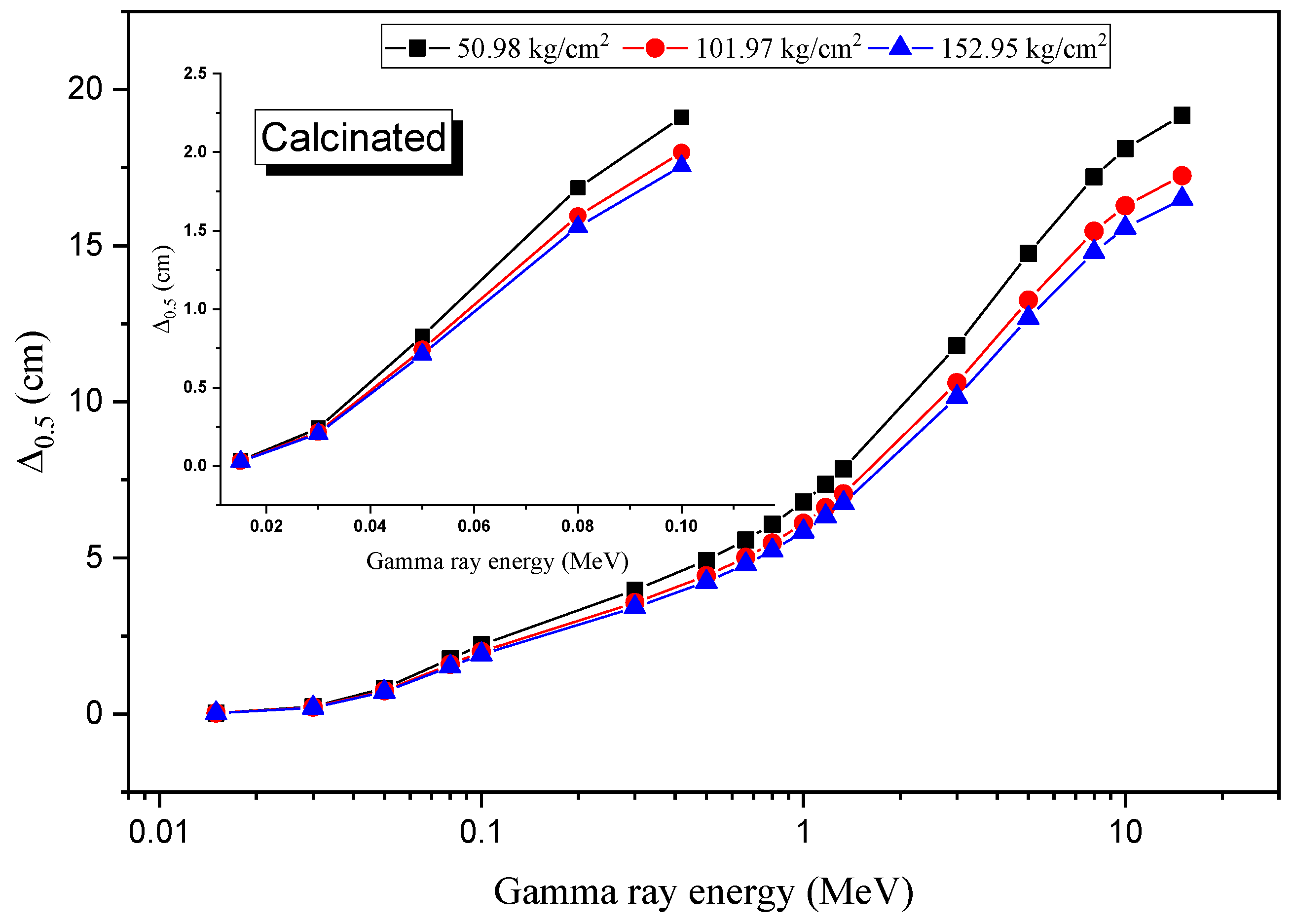
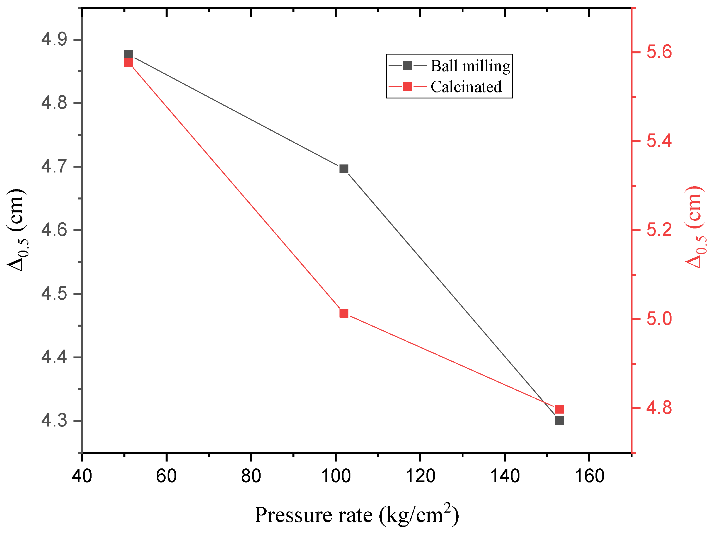
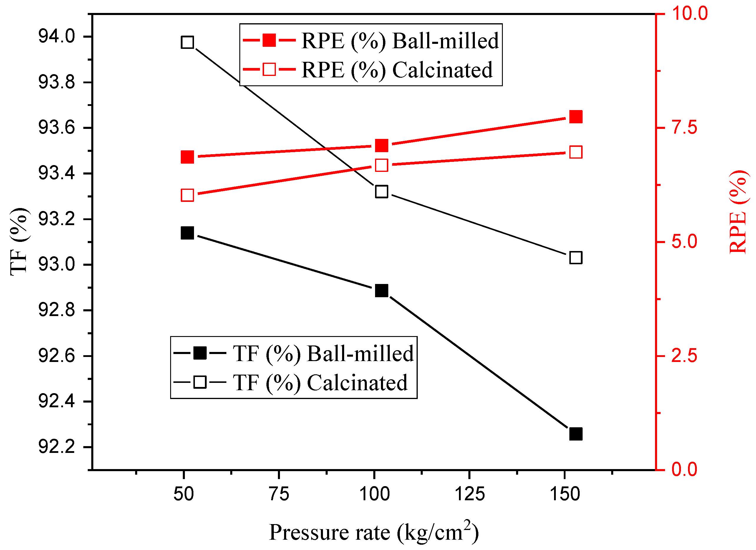
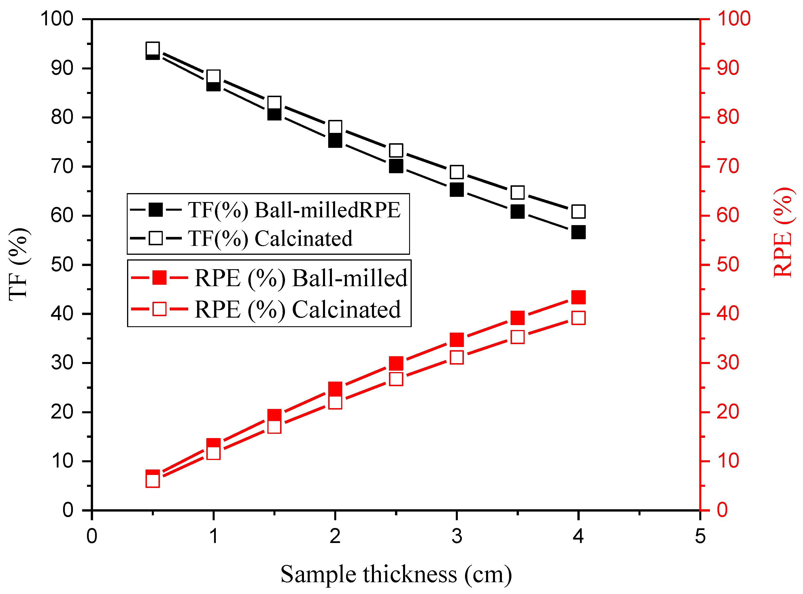
3.4. Radiation Shielding Evaluation

The Monte Carlo simulation (MC) for the µ of the fabricated ball-milled and calcinated bentonite samples showed that the µ for the fabricated samples mainly depended on the photon energy as well as the pressure rate at which the sample was fabricated. The µ values variation for the ball-milled bentonite versus the gamma-ray energy is illustrated in Figure 5 at various pressure rates (50.986, 101.971, and 152.957 kg/cm2). The simulated data showed that the µ decreased with raising the energy. Between 0.015 and 0.1 MeV, the µ decreased rapidly in the range between 22.956 and 0.357 cm−1 (samples under a pressure rate of 50.98 kg/cm2), 23.834 and 0.370 cm−1 (samples under a pressure rate of 101.97 kg/cm2), and 26.029 and 0.405 cm−1 (samples under a pressure rate of 152.95 kg/cm2). The high increase in the µ value is related to the proportionality of the interaction cross-section with E−3.5 in the mentioned energy interval. As the energy range in the Compton scattering region rises, the reduction of the µ is proportional to E−1 [24,25]. In this energy interval, the ball-milled µ values decrease in the range between 0.199 and 0.101 cm−1 (samples under a pressure rate of 50.98 kg/cm2), 0.207 and 0.105 cm−1 (samples under a pressure rate of 101.97 kg/cm2), and 0.226 and 0.114 cm−1 (samples under a pressure rate of 152.95 kg/cm2). In the last interaction area, where the Pp is the main interaction, the µ suffers a small variation with increasing the energy.
On the other hand, the calcinated bentonite’s µ values variation versus the applied energy is graphed in Figure 6. The variation in the µ values versus the energy is the same as presented in the ball-milled linear attenuation section. For the Pe region, the fabricated samples have µ values varied between 20.071 and 0.311 cm−1 (samples under a pressure rate of 50.98 kg/cm2), 22.330 and 0.347 cm−1 (samples under a pressure rate of 101.97 kg/cm2), and 23.332 and 0.362 cm−1 (samples under a pressure rate of 152.95 kg/cm2). Simultaneously, the µ values in the Cs region varied between 0.174 and 0.0883 cm−1 (samples under a pressure rate of 50.98 kg/cm2), 0.194 and 0.0982 cm−1 (samples under a pressure rate of 101.97 kg/cm2), and 0.203 and 0.1026 cm−1 (samples under a pressure rate of 152.95 kg/cm2). In addition, the variation in the Pp region is very tiny, as illustrated in the previous section.
The pressure rate is the second factor affecting the µ values in the present work. The µ’s variation for the ball-milled bentonite is illustrated in Figure 7. It is clear that increasing the pressure rate causes a notable improvement in the µ of the ball-milled bentonite samples. The µ increases from 0.142 to 0.161 cm−1 by increasing the pressure rate from 50.98 kg/cm2 to 152.95 kg/cm2 (these results are reported for E = 0.662 MeV). This increase recorded in the µ values is related to the grain size and the distance between the particles in the pressed ball-milled samples. Pressing the bentonite into nanoscale grain size decreases the distance between the sample bentonite particles. Thus, the incident gamma photons suffer a high resistance to pass through the fabricated pressed material. Thus, the incident photons performed many collisions along their path length inside the pressed fabricated material. The enhancement shown in the µ values for the ball-milled fabricated materials is superior to the µ values presented in Figure 8 for the calcinated bentonite samples using the same pressure rates. At 0.662 MeV, the µ values for the calcinated bentonite samples increased from 0.124 to 0.144 cm−1 by raising the pressure rate from 50.98 kg/cm2 to 152.95 kg/cm2. This also may be related to the calcinated bentonite’s particle grain size, which is in the micro-scale (calcinated bentonite is natural bentonite exposed to a temperature of around 800 °C to get rid of water and organic matter inside the natural bentonite). Thus, the distance between the particles inside the calcinated bentonite decreased under the pressing effect but was still higher than that in the ball-milled samples. Thus, the fabricated pressed calcinated bentonite density is still lower than that recorded for the ball-milled samples. Moreover, the energy deposited inside the calcinated bentonite is low compared to the ball-milled bentonite. As a result, the µ values for the calcinated bentonite are lower than those reported previously for the ball-milled bentonite at the same pressure rate.
The half-value thickness (Δ0.5) is the thickness of the material able to prevent half of the incident photons from penetrating the fabricated material (Figure 9). It is clear that the Δ0.5 has an increasing trend with increasing energy. These increases in the Δ0.5 are related to the radiation interaction model, as illustrated in the LAC section. For example, in the Pe interaction region, the Δ0.5 is highly increased from 0.030 to 1.942 cm with an average of 0.891 cm (samples under a pressure rate of 50.98 kg/cm2), from 0.0290 to 1.87 cm with an average of 0.0858 cm (samples under a pressure rate of 101.97 kg/cm2), and from 0.0266 to 1.713 cm with an average of 0.785 cm (samples under a pressure rate of 152.95 kg/cm2). These rapid increases in the Δ0.5 values are due to the variation in the interaction cross-section for the gamma photons with E−3.5. In the Cs interaction region, the Δ0.5 values increase from 3.474 to 6.862 cm with an average of 5.316 cm (samples under a pressure rate of 50.98 kg/cm2), from 3.346 to 6.609 cm with an average of 5.120 cm (samples under a pressure rate of 101.97 kg/cm2), and from 3.064 to 6.052 cm (samples under a pressure rate of 152.95 kg/cm2). Consequently, the increase in the Δ0.5 became slightly semi-independent of the energy.
Figure 10 shows that the change in the Δ0.5 for the calcinated bentonite is the same as in the ball-milled samples. Furthermore, Figure 10 shows that Δ0.5 for the calcinated bentonite is thicker than that recorded for the ball-milled bentonite. In the Pe Interaction region, for example, the Δ0.5 increases from 0.0345 to 2.221 cm with an average of 1.019 cm (samples under a pressure rate of 50.98 kg/cm2), from 0.310 to 1.997 cm with an average of 0.916 cm (samples under a pressure rate of 101.97 kg/cm2), and from 0.0297 to 1.997 cm with an average of 0.876 cm (samples under a pressure rate of 152.95 kg/cm2).
The variation in Δ0.5 versus the pressure rate for both samples is graphed in Figure 11. It is clear that the thinner Δ0.5 achieved for the ball-milled calcinated bentonite where the Δ0.5 values were at 0.662 MeV decreased from 4.876 to 4.697 cm when raising the pressure rate from 50.98 to 101.97 kg/cm2. The Δ0.5 values decreased from 5.577 to 4.797 cm when the pressure rate increased from 50.98 to 101.97 kg/cm2 for the calcinated bentonite. These results show that ball milling for the calcinated bentonite improved the Δ0.5 of the fabricated samples from 5.577 to 4.876 cm, at a pressure rate of 50.98 kg/cm2 and at 0.662 MeV, for example. The results demonstrated that the Δ0.5 was enhanced by a factor of 12.568% when the grain size of the calcinated bentonite decreased using the ball-milling process and the samples were compressed at a pressure rate of 50.98 kg/cm2.
The gamma-ray transmission factor (TF) and the fabricated samples’ radiation shielding efficiency (RPE) were reported for the fabricated ball-milled and calcinated bentonite. The TF factor determines the number of transmitted photons through the fabricated materials. Both TF and RPE are affected by three factors: incident gamma photon energy, pressure rate, and sample thickness. Regarding the first factor, the values of TF increase with raising the energy. Regarding the pressure rate, the TF and RPE were calculated and plotted versus the pressure rate, as presented in Figure 12. The TF values decrease with increasing the pressure rate while the RPE increases with increasing the pressure rate. At 0.662 MeV, the TF values slightly decreased from 93.139 to 92.257%. Using the same energy, the RPE increased from 6.860 to 7.742% when the pressure rate was raised from 50.98 to 152.95 kg/cm2 for the ball-milled calcinated bentonite. In addition, for the calcinated bentonite sample, the TF values decreased from 93.97 to 93.03%, while the RPE increased from 6.02 to 6.96% when the pressure rate was raised from 50.98 to 152.95 kg/cm2. The variation in TF and RPE versus the pressure rate clarifies that increasing the pressure rate causes a decrease in the inner distance between the bentonite particles, which generates more resistance for the passing photons. Thus, the amount of energy lost in the fabricated material increases with increasing the pressure rate. Therefore, the photons transmitted through the material decreased (i.e., TF decreased) which is associated with an increase in the fabricated materials’ RPE.
The third factor is the fabricated material thickness, where the TF values decrease when the fabricated material thickness increases, as clarified in Figure 13. As the fabricated sample thickness increases, the path length of gamma photons inside the fabricated material will increase. Therefore, the photons inside the thicker material will perform a higher number of collisions than in the thinner material [25,26]. Thus, the amount of energy lost inside a thicker material is high compared to a thinner material. This means that the RPE for the thicker material is superior to that of the thinner material. In contrast, the TF of thinner materials is higher than that of thicker materials. At 0.662 MeV and a pressure rate of 50.98 kg/cm2, the TF values decreased from 93.139 to 56.633%. At the same time, the RPE rose from 6.860 to 43.366% when the fabricated material’s thickness was increased from 0.5 to 4 cm for the ball-milled calcinated bentonite. On the other hand, at the same energy and pressure rate, the calcinated bentonite’s TF values decreased from 93.975 to 60.828%, while the RPE rose from 6.025 to 39.171% when the material thickness was increased from 0.5 to 4 cm.

4. Conclusions

In the present work two composites were fabricated based on calcinated and ball-milled calcinated bentonite. The density of the fabricated composites increased by 16.25% for the calcinated bentonite and increased by 13.38% for the ball-milled calcinated bentonite when the pressure rate increased from 50.98 to 152.92 Kg/cm2. XRD was used to study the crystalline phase of the fabricated composites. Furthermore, the Monte Carlo simulation code MCNP was utilized to evaluate the µ values of the fabricated composites. The photon shielding capacity of the composites was analyzed. The results concluded that the ball-milled calcinated bentonite has a linear attenuation coefficient value of between 0.14214 and 0.16117 cm−1. Simultaneously, the µ values of the calcinated bentonite varied between 0.1243 and 0.14447 cm−1 when the pressure rate varied between 50.98 and 152.95 Kg/cm2 at 0.662 MeV.

Author Contributions

Conceptualization, F.H.S. and A.H.A.; methodology, F.H.S. and K.A.M.; software, K.A.M. and M.I.S.; validation, M.I.S. and D.A.A.; formal analysis, K.A.M.; investigation, D.A.A.; resources, F.H.S.; data curation, A.H.A.; writing—original draft preparation, F.H.S. and K.A.M.; writing—review and editing, M.I.S.; visualization, K.A.M.; supervision, A.H.A.; project administration, D.A.A.; funding acquisition, D.A.A. All authors have read and agreed to the published version of the manuscript.

Funding

The authors express their gratitude to Princess Nourah bint Abdulrahman University Researchers Supporting Project number (PNURSP2022R57), Princess Nourah bint Abdulrahman University, Riyadh, Saudi Arabia.

Institutional Review Board Statement

The study did not require ethical approval.

Informed Consent Statement

Not applicable.

Data Availability Statement

Data available on request due to restrictions eg privacy or ethical.

Acknowledgments

The authors express their gratitude to Princess Nourah bint Abdulrahman University Researchers Supporting Project number (PNURSP2022R57), Princess Nourah bint Abdulrahman University, Riyadh, Saudi Arabia.

Conflicts of Interest

The authors declare no conflict of interest.

References

  1. Beir, V. Health Effects of Exposure to Low Levels of Ionizing Radiation; National Academies Press (US): Washington, DC, USA, 1990. [Google Scholar]
  2. Agar, O. Study on Gamma Ray Shielding Performance of Concretes Doped with Natural Sepiolite Mineral. Radiochim. Acta 2018, 106, 1009–1016. [Google Scholar] [CrossRef]
  3. González-Ortega, M.A.; Segura, I.; Cavalaro, S.H.P.; Toralles-Carbonari, B.; Aguado, A.; Andrello, A.C. Radiological Protection and Mechanical Properties of Concretes with EAF Steel Slags. Constr. Build. Mater. 2014, 51, 432–438. [Google Scholar] [CrossRef]
  4. Agar, O.; Tekin, H.O.; Sayyed, M.I.; Korkmaz, M.E.; Culfa, O.; Ertugay, C. Experimental Investigation of Photon Attenuation Behaviors for Concretes Including Natural Perlite Mineral. Results Phys. 2019, 12, 237–243. [Google Scholar] [CrossRef]
  5. Allam, E.A.; El-Sharkawy, R.M.; El-Taher, A.; Shaaban, E.R.; Massoud, E.E.S.; Mahmoud, M.E. Enhancement and Optimization of Gamma Radiation Shielding by Doped Nano HgO into Nanoscale Bentonite. Nucl. Eng. Technol. 2022, 54, 2253–2261. [Google Scholar] [CrossRef]
  6. Asal, S.; Erenturk, S.A.; Haciyakupoglu, S. Bentonite Based Ceramic Materials from a Perspective of Gamma-Ray Shielding: Preparation, Characterization and Performance Evaluation. Nucl. Eng. Technol. 2021, 53, 1634–1641. [Google Scholar] [CrossRef]
  7. El-Khatib, A.M.; Elsafi, M.; Almutiri, M.N.; Mahmoud, R.M.M.; Alzahrani, J.S.; Sayyed, M.I.; Abbas, M.I. Enhancement of Bentonite Materials with Cement for Gamma-Ray Shielding Capability. Materials 2021, 14, 4697. [Google Scholar] [CrossRef]
  8. Hasan, W.K.; Mahdi, J.T.; Hameed, A.S. Measurement Technique of Linear and Mass Attenuation Coefficients of Polyester—Bentonite Composite as Gamma Radiation Shielding Materials. AIP Conf. Proc. 2019, 2144, 030018. [Google Scholar] [CrossRef]
  9. Hager, I.Z.; Rammah, Y.S.; Othman, H.A.; Ibrahim, E.M.; Hassan, S.F.; Sallam, F.H. Nano-Structured Natural Bentonite Clay Coated by Polyvinyl Alcohol Polymer for Gamma Rays Attenuation. J. Theor. Appl. Phys. 2019, 13, 141–153. [Google Scholar] [CrossRef] [Green Version]
  10. Orolínová, Z.; Mockovčiaková, A.; Dolinská, S.; Briančin, J. Uticaj termičke obrade na bentonitska svojstva. Arch. Tech. Sci. 2012, 4, 49–56. [Google Scholar] [CrossRef]
  11. Darweesh, M.; Nagieb, Z.A. Hydration of Calcined Bentonite Portland Blended Cement Pastes. Indian J. Chem. Technol. 2007, 14, 301–307. Available online: http://nopr.niscpr.res.in/handle/123456789/1124 (accessed on 1 July 2022).
  12. Mote, V.; Purushotham, Y.; Dole, B. Williamson-Hall Analysis in Estimation of Lattice Strain in Nanometer-Sized ZnO Particles. J. Theor. Appl. Phys. 2012, 6, 6. [Google Scholar] [CrossRef] [Green Version]
  13. Prabhu, Y.T.; Rao, K.V.; Kumar, V.S.S.; Kumari, B.S. X-Ray Analysis by Williamson-Hall and Size-Strain Plot Methods of ZnO Nanoparticles with Fuel Variation. World J. Nano Sci. Eng. 2014, 4, 21–28. [Google Scholar] [CrossRef]
  14. Sallam, F.H.; Ibrahim, E.M.; Hassan, S.F.; Omar, A. Enhanced Bentonite/PVA Matrix for Advanced Shielding Applications. Nucl. Technol. 2022, 1–15. [Google Scholar] [CrossRef]
  15. Suryanarayana, C.; Norton, M.G. X-ray Diffraction; Springer: Boston, MA, USA, 1998; ISBN 978-1-4899-0150-7. [Google Scholar]
  16. X-5 Monte Carlo Team. MCNP—A General Monte Carlo N-Particle Transport Code, Version 5. La-Ur-03-1987 2003, 1–100. Available online: https://mcnp.lanl.gov/pdf_files/la-ur-03-1987.pdf (accessed on 1 July 2022).
  17. Mahmoud, K.A.; Sayyed, M.I.; Alhuthali, A.M.S.; Hanfi, M.Y. The Effect of CuO Additive on the Mechanical and Radiation Shielding Features of Li2B4O7–Pb2O3 Glass System. Boletín De La Soc. Española De Cerámica Y Vidr. 2022, 61, 275–283. [Google Scholar] [CrossRef]
  18. Kilic, G.; Ilik, E.; Mahmoud, K.A.; El-Agawany, F.I.; Alomairy, S.; Rammah, Y.S. The Role of B2O3 on the Structural, Thermal, and Radiation Protection Efficacy of Vanadium Phosphate Glasses. Appl. Phys. A Mater. Sci. Processing 2021, 127, 265. [Google Scholar] [CrossRef]
  19. Abu El-Soad, A.M.; Sayyed, M.I.; Mahmoud, K.A.; Şakar, E.; Kovaleva, E.G. Simulation Studies for Gamma Ray Shielding Properties of Halloysite Nanotubes Using MCNP-5 Code. Appl. Radiat. Isot. 2019, 154, 108882. [Google Scholar] [CrossRef]
  20. Boussaa, S.A.; Kheloufi, A.; Zaourar, N.B.; Kerkar, F. Valorization of Algerian Sand for Photovoltaic Application. Acta Phys. Pol. A 2016, 130, 133–137. [Google Scholar] [CrossRef]
  21. Barhoum, A.; Van Assche, G.; Makhlouf, A.S.H.; Terryn, H.; Baert, K.; Delplancke, M.-P.; El-Sheikh, S.M.; Rahier, H. A Green, Simple Chemical Route for the Synthesis of Pure Nanocalcite Crystals. Cryst. Growth Des. 2015, 15, 573–580. [Google Scholar] [CrossRef]
  22. Tang, Q.; Chen, X.Y.; Hu, W.B.; Zhou, G.Y. Microwave-Assisted Hydrothermal Synthesis of Hexagonal Columnar-Shaped Calcium Carbonate. Adv. Mater. Res. 2011, 239, 1643–1648. [Google Scholar] [CrossRef]
  23. Alsaif, N.A.M.; Alotiby, M.; Hanfi, M.Y.; Mahmoud, K.A.; Al-Yousef, H.A.; Alotaibi, B.M.; Sayyed, M.I.; Al-Hadeethi, Y. Comprehensive Study of Radiation Shielding and Mechanical Features of Bi2O3-TeO2-B2O3-GeO2 Glasses. J. Aust. Ceram. Soc. 2021, 57, 1267–1274. [Google Scholar] [CrossRef]
  24. Kumar, A.; Jain, A.; Sayyed, M.I.; Laariedh, F.; Mahmoud, K.A.; Nebhen, J.; Khandaker, M.U.; Faruque, M.R.I. Tailoring Bismuth Borate Glasses by Incorporating PbO/GeO2 for Protection against Nuclear Radiation. Sci. Rep. 2021, 11, 7784. [Google Scholar] [CrossRef] [PubMed]
  25. Sazirul, I.; Mahmoud, K.A.; Sayyed, M.I.; Alim, B.; Rahman, M.d.M.; Mollah, A.S. Study on the radiation attenuation properties of locally available bees-wax as a tissue equivalent bolus material in radiotherapy. Radiat. Phys. Chem. 2020, 172, 108559. [Google Scholar]
  26. Mahmoud, K.A.; Abu El-Soad, A.M.; Kovaleva, E.G.; Sayyed, M.I.; Tashlykov, O.L. Modeling a three-layer container based on halloysite nano-clay for radioactive waste disposal. Prog. Nucl. Energy 2022, 152, 104379. [Google Scholar] [CrossRef]
Figure 1. XRD patterns for the calcinated and ball-milled bentonite clay. Clay minerals denoted are calcite (C), quartz (Q), and hematite (H).
Crystals 12 01178 g001
Figure 2. The particle size of (a) calcinated bentonite and (b) ball-milled bentonite by Williamson–Hall size analysis.
Crystals 12 01178 g002
Figure 3. TEM of (a) the calcinated bentonite sample (b) and the ball-milled calcinated bentonite.
Crystals 12 01178 g003
Figure 4. Effect of the pressure rate on the density of both calcinated and ball-milled bentonite.
Crystals 12 01178 g004
Figure 5. The linear attenuation coefficient for ball-milled bentonite at various gamma-ray energies.
Crystals 12 01178 g005
Figure 6. The LAC for calcinated bentonite at various gamma-ray energies.
Crystals 12 01178 g006
Figure 7. Variation in the LAC of the ball-milled bentonite as a function of the pressure rate (kg/cm2).
Crystals 12 01178 g007
Figure 8. Variation in the linear attenuation coefficient of the calcinated bentonite as a function of the pressure rate (kg/cm2).
Crystals 12 01178 g008
Figure 9. Variation in the half-value thickness versus the energy for the ball-milled bentonite.
Crystals 12 01178 g009
Figure 10. Variation in the Δ0.5 versus the gamma-ray energy for the calcinated bentonite.
Crystals 12 01178 g010
Figure 11. Variation in the Δ0.5 versus the pressure rate for both calcinated and ball-milled bentonite.
Crystals 12 01178 g011
Figure 12. Variation in the TF and the RPE versus the pressure rate at 0.662 MeV.
Crystals 12 01178 g012
Figure 13. Variation in the TF and RPE versus the sample thickness at a pressure rate of 50.98 kg/cm2.
Crystals 12 01178 g013
Table 1. Percentages of mineral oxides presented in calcinated bentonite.
Oxides (%)SiO2Al2O3CaOFe2O3MgONa2OK2OP2O5TiO2L.O.ITotal
Calcinated29.6013.7034.204.203.801.900.8100.540.458.6797.87
Publisher’s Note: MDPI stays neutral with regard to jurisdictional claims in published maps and institutional affiliations.

