Review

An Overview on the Process Development and the Formation of Non-Dendritic Microstructure in Semi-Solid Processing of Metallic Materials

1
Brunel Centre for Advanced Solidification Technology (BCAST), Brunel University London, Uxbridge, Middlesex UB8 3PH, UK
2
College of Materials Science and Engineering, Chongqing University, Chongqing 400044, China
*
Author to whom correspondence should be addressed.
Crystals 2022, 12(8), 1044; https://doi.org/10.3390/cryst12081044
Submission received: 23 May 2022 / Revised: 13 June 2022 / Accepted: 17 June 2022 / Published: 27 July 2022
(This article belongs to the Special Issue Semi-solid Processing: Fundamentals and Applications)

Abstract

:
Semi-solid metal (SSM) processing has been an attractive method for manufacturing near-net-shape components with high integrity due to its distinct advantages over conventional forming technologies. SSM processing employs a mixture of solid phase and liquid metal slurries and/or non-dendritic feedstocks as starting materials for shaping. Since the original development from 1970s, a number of SSM processes have been developed for shaping components using the unique rheological and/or thixotropic properties of metal alloys in the semi-solid state, in which the globular solid particles of primary phase are dispersed into a liquid matrix. In this paper, the progress of the development of shaping technologies and the formation of non-dendritic microstructure in association with the scientific understanding of microstructural evolution of non-dendritic phase are reviewed, in which the emphasis includes the new development in rheomoulding, rheo-mixing, rheo/thixo-extrusion and semi-solid twin roll casting, on the top of traditional rheocasting, thixoforming and thixomoulding. The advanced microstructural control technologies and processing methods for different alloys are also compared. The mechanisms to form non-dendritic microstructures are summarised from the traditional understanding of mechanical shear/bending and dendrite multiplication to the spheroidal growth of primary phase under intensively forced convection. In particular, the formation of spheroidal multiple phases in eutectic alloys is summarised and discussed. The concluding remarks focus on the current challenges and developing trends of semi-solid processing.

1. Introduction

Semi-solid metal (SSM) processing was developed following the discovery of the pseudoplastic properties of metallic alloys at different temperatures between the liquidus and solidus [1,2]. After nearly fifty years’ development, SSM processing has been successfully established as a unique technique for manufacturing the high integrity products with improved mechanical properties [3,4]. Different from the conventional metal forming technologies that use either solid state materials (forging) or liquid metals (casting) as starting materials, SSM processing uses a mixture of solid and liquid metal slurries, in which non-dendritic solid particles are dispersed in a liquid matrix. Figure 1 shows the morphological difference between the typical dendritic microstructure formed under conventional solidification and the non-dendritic solid particles formed under intensively forced convection.
In general, casting is more competitive than forging in terms of cost, while forging is capable of offering the best mechanical performances because of the high integrity. Semi-solid process can reduce the gap between casting and forging in terms of defect control and mechanical performance. The components manufactured by the semi-solid process can achieve a low level of defects (shrinkage or gas porosities, segregations, and surface defects) in comparison with castings [5]. Therefore, the components are heat-treatable, weldable and capable of offering improved mechanical properties. Productivity can be improved through SSM processing because of the shorter production cycle time than that in forging. Meanwhile, because the semi-solid slurries release less latent heat within the die cavity during solidification, the thermal shocks on the die are reduced and the die life is improved [6]. In addition, die wear may be lower than that in high pressure die casting due to the low injection speed. The casting surfaces can be free from blisters, and the heat treatment can be applied to the castings for further improvement of mechanical properties [7].
SSM processing can be technically divided into two basic routes: rheo-route and thixo-route [3,4]. The SSM processing and the associated theories and mechanisms have been extensively developed and a number of processes have been used in industry in the past several decades. The main techniques include rheocasting [8], thixocasting, thixoforging, rheomoulding [9], thixomoulding [10], rheo-extrusion [11], thixo-extrusion [12], semi-solid joining [13], semi-solid twin roll casting [14], and rheo-mixing etc. Several comprehensive reviews have been published in 1991 [1], 1994 [2], 2002 [3], 2005 [4], 2018 [15,16], 2019 [17], 2020 [18], and 2021 [19]. This overview will mainly focus on the process development for component manufacturing, techniques for generating the non-dendritic microstructure and the associated mechanisms in the microstructural evolution of non-dendritic primary phase. It is necessary to note that the alloy development, pseudo-plasticity and thixotropy of semi-solid slurry and non-dendritic feedstock, microstructural evolution during shaping, the die filling and deformation mechanisms of semi-solid slurry and non-dendritic feedstock, the mechanical properties of finished components and the mechanism of defect formation are all the critical aspects for the success of SSM processing. Although these are not reviewed in the present paper, it needs to be essentially understood as a whole for SSM processing.

2. Process Development for Component Manufacturing

2.1. Rheocasting

Rheocasting starts from liquid alloys to prepare semi-solid slurry containing fine globular primary phase through solidification, which is immediately transferred into a die-casting machine for shaping the final products. In rheocasting, a conventional high pressure die casting (HPDC) machine is usually used for shaping, in which the injection speed is reduced in comparison with that used in conventional HPDC process [3,7,8]. The feeding slurry can be produced by a variety of processes, which will be introduced in the following part of this paper. With necessary process modification, rheocasting can produce complex-shaped components with improved integrity. The significant advantage of rheocasting is that the slurry with globular structure can be made on-demand and onsite [1,3]. The raw material can be any standard alloys that are usable for other methods like squeeze, gravity or HPDC process. The chemical composition can also be modified and tailored to meet the quality and property specifications of the components. Moreover, the rheocasting does not need to import specially made material with non-dendritic microstructure. Scraps and runners can be directly re-melted and recycled onsite during rheocasting, which can significantly lower the production cost.
One of the most industrially successful developments is the new rheocasting (NRC) [20,21]. The principle of NRC process is shown in Figure 2. In the NRC process, the conventional vertical indirect squeeze casting technology is combined with an innovative method for preparing the globular precursor material with thixotropic properties. A melt with low level of superheat is taken from the holding furnace as starting materials [22]. The melt is poured into a specially designed steel vessel and kept there for a predefined time to cool the melt down in a controlled manner, in which a cooling air may be used to offer required cooling rates. Then the materials inside the vessel is conditioned by induction heating to equalize the temperature throughout the vessel to form fine and non-dendritic primary phase in the slurry, followed by charging the materials into the inclined sleeve of a vertical squeeze casting machine for component shaping. Die filling is required to be slow with a controlled manner. The semi-solid material is filled into die cavity from the bottom upwards, allowing a laminar flow and the air is pushed out of the die cavity without entrapment into the shaped casting. Final solidification occurs in the die under a high pressure [23]. During NRC process, it is understood that the primary phase in the melt starts to solidify and it is uniformly distributed within the vessel by the continuous pouring the melt into the vessel. The solid primary phase is continuously growing in the vessel until the materials are conditioned to the required temperature [22]. The development of dendritic structures is prevented by multiple cycles of cooling and heating of the suspension in the vessel until the uniform globular structure is achieved [24]. The NRC process has been industrially available in several countries for a variety of castings.

2.2. Thixoforming

Thixoforming is a process to make near-net-shape components from a partially melted non-dendritic alloy feedstock within a metal die. Two independent stages are involved in the thixoforming process [1]. The first stage is uniform heating and partial re-melting of the specially made non-dendritic billet/feedstock to a semi-solid state and the second stage is forming the components. After solidification, the shaped components are removed from the die for subsequent processing [25]. When the components are shaped in a closed die, it is named as thixocasting, while the shaping is performed in an open die, it is termed as thixoforging [1]. Figure 3 shows the schematic layout of different forming processes. The main advantages of thixoforming are that the forming facility is not associated with liquid metal handling, and the process can be automated by the approaches similar to forging and stamping [26]. The separation of the two main steps in the process has offered capability of developing the individual process route industrially. However, as it is difficult to obtain fully homogenized billets because the billets are usually inhomogeneity with respect to both structure and composition, the components made from thixoforming are hardly homogeneous in composition and mechanical properties [27]. Meanwhile, there is up to 10% of metal loss during the reheating. Gates and risers are not recycled within the forming facilities and need to send back to the ingot producers. As a result, the manufacturing cost is increased. Currently, up to 50% of the cost for thixotropic feedstock is a heavy burden for component manufacturers.
Reheating to the semi-solid state is a critical phase in thixoforming process. It is essential to provide semi-solid feedstock with an accurate control of solid fraction with fine and spheroidal particles in the liquid matrix. The accurate and uniform heating at processing temperatures throughout the heating cycles are important during the reheating process, and it is understood that the heating temperature determines the solid fraction of the feedstock [4]. The inappropriate heating causes the instable feedstock for handling and inadequate volume fraction in the feedstock. The non-uniform distribution of temperature leads to the fluctuation of solid fraction and rheological characteristics in different positions, which in turn cause the difference in formability and the solid/liquid separation during die filling. More importantly, the non-uniform microstructure leads to non-uniform mechanical properties in the finished components. Therefore, the heating time needs to be optimized. The prolonged heating will cause coarsening of the primary phase, but the insufficient heating time will lead to incomplete spheroidization of the solid particles, which also results in inadequate rheological properties and difficulties during die filling. Currently, reheating is mainly achieved by induction heating [4], which has the advantages of precise and fast heating and capable of satisfying the requirement in SSM processing. However, the relatively low energy efficiency of induction heating is a drawback [28].
Parameter optimization during shaping is also critical to ensure a high quality of finished components. The optimizations generally include process optimization and modelling for the forming process, which takes place with casting process as thixocasting or with forging process as thixoforging [4]. Nowadays, thixocasting through horizontal cold chamber die-casting is the dominant process because thixocasting process can be real-time controlled. As laminar die filling is essential for the forming process, the shot profiles for specific alloys must be optimized in association with their physical conditions. Moreover, the design of gating system and die cavity, and the correct choice of die temperature are very important for the forming process. Because of the reduced filling speed and reduced solidification shrinkage, the design of gate size and geometric tolerance should be slightly different to that used in conventional HPDC process.

2.3. Rheomoulding

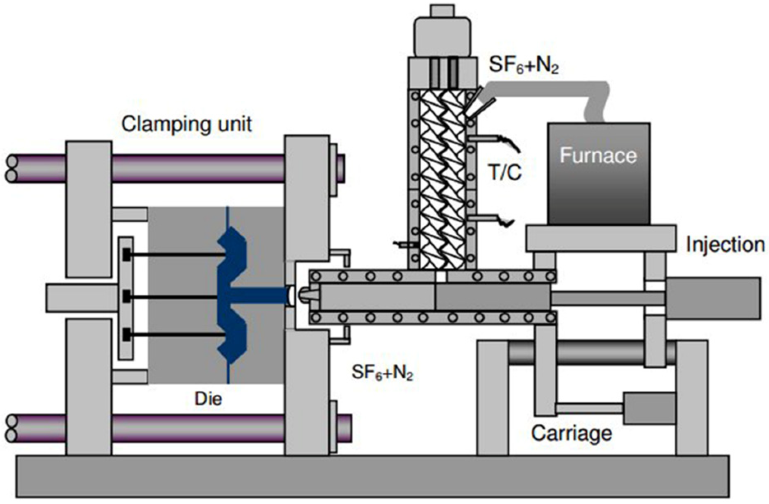
Rheomoulding is a one-step process that uses liquid alloy as starting materials and applies shear through screws to create semi-solid slurries, which are immediately injected into a die cavity, as shown in Figure 4 [9,29]. There are two different types of mechanisms that can be employed in rheomoulding process: a single screw or a twin screw. The rheomoulding with a single screw was developed using a vertically positioned single screw to shear Sn–Pb and Zn–Al–Cu alloys [30], in which the viscous drag-induced materials transport along the profile in the single-screw extruder delivers the materials from one end to another end while the alloy is cooled down to semi-solid processing temperature with various shear rates. The semi-solid slurry with globular primary phase is transferred into a chamber connected to the screw profile and equipped with a non-return value. The quick forward of the single screw pushes the semi-solid slurry into a die cavity. The twin-screw rheomoulding was developed by Ji et al. [29] for magnesium alloys, in which a very high shear rate is generated by a pair of self-wiping and co-rotating screws. They consider the transport behaviour in the closely intermeshing twin-screw extruder as a positive displacement type of transport, being independent of the viscosity of the molten materials approximately. It was analysed that the principal forces acting on the materials include compression, rupture, shear and elasticity owing to the constraint of the two screws and the barrel on the prepared materials. The rotation motion of fluid moves around the periphery of the screws with ‘Figure 8’ motions, and push fluid from one pitch to the next one along the axial direction of the screws, forming a ‘Figure 8’ helix consequently. In this process, the liquid metal is fed into the barrel, the liquid metal change into semi-solid slurry due to the cooling and shearing. After that the slurry is injected into a die cavity to form the final shapes. This type of process is appropriate for the massive production of components without the process of making special feedstock material.

2.4. Thixomoulding

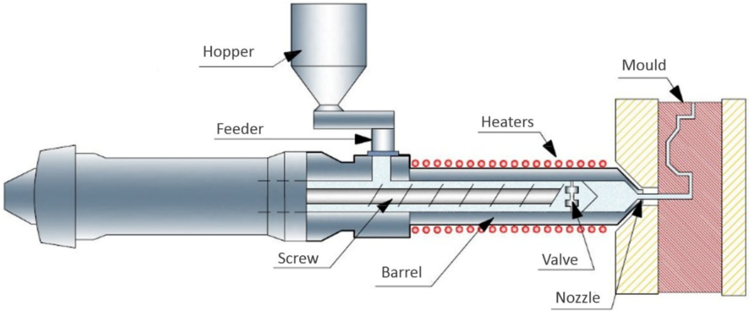
Thixomoulding is a technique especially for the production of high quality and near net-shape magnesium parts [31,32]. The thixomoulding process is schematically illustrated in Figure 5 [33]. Magnesium alloys in particulate or granule format are fed into a pre-heated barrel, in which a reciprocating screw is installed and rotated during operation. Barrel is normally heated to about 600 °C to partially melt the magnesium granules. The screw rotation generates shear within the magnesium and homogenizes the semi-solid mixture with uniform temperature. The continuous feeding of magnesium granules pushes the thixotropic alloy flow forward along the barrel into a heated die through a nozzle that is connected with the sprue and runners in the die. The metal is normally protected by argon to prevent oxygen pickup and burning of magnesium. Thixomoulding process is similar to injection moulding system, but the higher processing temperature and materials protection are essential for thixomoulding process [34]. The main difference between rheomoulding and thixomoulding is that the raw material used in thixomoulding is feedstock in the form of chips of magnesium alloy, but the starting material in rheomoulding is liquid metal. The main advantages of thixomoulding are that the forming operations can be done in a one-step process which takes place in a clean and safe environment, because the handling of liquid metal is completely eliminated and the process can be used for the continuous production of large quantities of components [35]. Thixomoulding has been used in industry from the products like the cover for cell phones to the structural products for automotive industry [36].

2.5. Thixojoining

As a semi-solid process, thixojoining combines forming and bonding into an one-step method using the enable ability of joining at semi-solid state [37]. In thixojoining, at least two metals are joined using the thixotropic metal as the filler [38,39,40]. In spite of some technological differences among the available thixojoining processes, they can be categorized into four types: (1) adding new functional features, (2) joining metals by using semi-solid metal slurries, (3) semi-solid metal stir joining, and (4) semi-solid metal diffusion joining. Because the inclusions of additional inserts are allowably existed in semi-solid matrix without showing a significant detrimental effect, thixojoining can provide an improvement in the functionality and complexity of components. Owing to the changes of flowability during forming the semi-solid materials, the addition of functional features to shaped components is easier comparing to that formed under solid state. Commonly, three ways can be possibly applied in order to obtain the additional functionality: (1) some special contours such as screw threads to be forged, [41]; (2) components with extra functions to be added by joining in semi-solid state. For example, steel pins can be placed into aluminium semi-solid slurry [42]; and (3) adding functions through the combination of forming and joining [37]. The achievement of hybrid structures using thixo-joining is one of the most attractive methods using SSM processing. It is understood that the processing temperature, pressure applied on the bonding pieces and the duration of joining are critical factors to affect the quality of joining on top of the materials type to be joined through SSM processing. The microstructure after bonding is in globular morphology, which is the same as that observed in other semi-solid microstructures [43,44]. In order to successfully operate the thixojoining, the solid primary phase in the microstructure of premade starting material needs to be near-globular or non-dendritic grains surrounded by a liquid matrix and a wide solidus−to−liquidus transition area.
Currently, this process is industrially successful, generating a variety of hybrid structural products with high quality in different industrial sectors. Table 1 summaries the typical materials joined by SSM joining technique. Compared with conventional joining methods, the advantages of thixojoining include the capability of producing functional components with multiple materials, manufacturing of hybrid structure with minimized defects, joining different components with significant thickness variation. In addition, the semi-solid joining can be effective in a metal with low melting point and a metal with high melting point [45,46]. With this technology, it is possible to shorten the joining process. Since the thixojoining process is not based on conventional methods such as adhesive, nails and screws joining, it is able to produce homogeneous properties with a high-quality surface. In addition, it is possible to produce desirable bonding in association with other methods.

2.6. Rheo-Extrusion and Thixo-Extrusion

Extrusion under semi-solid state usually includes thixo-extrusion and rheo-extrusion. In thixo-extrusion process, a solid billet is firstly heated up to a temperature between the solidus and the liquidus temperatures of the alloy, then the obtained semi-solid feedstock is introduced into a cylinder piston mechanism for extrusion. The extrusion behaviour of semi-solid Zn-20Al alloy has been investigated by Zhang et al. [63], and they found that the appropriate operation temperature for semi-solid extrusion of Zn-20A1 alloy is from 400 to 420 °C. A lowered temperature leads to the crack formation, while an increased temperature results in the liquid segregation during extrusion and subsequently non-uniform mechanical properties in semi-solid products. The extrusion force required for semi-solid alloys is much less than that required for hot or cold extrusion in the solid state. The semi-solid extrusion of SiCp/2014Al composite was studied by Zu and Luo [64] and confirmed that only 1/3 to 1/5 of the forces are required during semi-solid extrusion comparing to the forces required for solid extrusion. Semi-solid extrusion can successfully make SiCp/2014Al composites with substantially improved mechanical properties. The yield strength is increased by 66-131 MPa, the ultimate tensile strength is increased by 43–87 MPa and the modulus is increased by 18–36 MPa while the elongation is maintained at 3.8–8.4%. The study carried out by Uetani, et al. [65] for the semi-solid extrusion of Al-10Mg alloy uses a simple mechanical stirring treatment to form non-dendritic microstructure in the billet. They obtained an improvement in ductility and less surface cracking for the extruded products. The semi-solid extrusion of AZ61A wrought magnesium alloy by Sugiyama, et al. [66] confirmed that high quality products can be made by semi-solid extrusion, in which the extrusion parameters have to be carefully controlled to avoid the defects formation in the extruded products. During semi-solid extrusion of AZ31 magnesium alloy, plastic deformation and recrystallization and occurred simultaneously, leading to fine grain size, weakened texture and improved mechanical properties [67]. Neag, et al. [68] studied 7075 Al-alloy and found the presence of a solid fraction limit at a level of 0.77 during semi-solid extrusion. The surface quality of the extruded components will be probably decreased because of the out of the limit for processing. Thixo-extrusion has also used to process steels such as 100Cr65 [69], HS6-5-2 [70], 9Cr18 [71] and X210CrW12 (AISI D6) [72,73].
For rheo-extrusion, the fabrication of semi-solid slurry and extruding profiles usually occur simultaneously. For example, Guan, et al. [74] has successfully extruded AZ31 alloy wire using continuous semi-solid extrusion process to reduce the non-unaffordability in microstructures. The appropriate parameters for the semi-solid extrusion include 730–750 °C of the processing temperature, 0.4 L/s of the roll cooling is and <10 mm of the roll-shoe gap width. The tensile strength and the elongation of the extruded 10 mm bar can reach 270 MPa and 16%, respectively, under the condition of artificial ageing at 220 °C for 24 h. Rattanochaikul, et al. [75,76] combined the manufacturing of semi-solid slurry with extrusion to fabricate A356 Al profiles and found that the surface defects in extruded parts can be significantly reduced. A twin screw extruder was used to develop the rheo-extrusion by Fan, et al. [77] and Roberts, et al. [78], by which the primary phase in the extruded alloys show a relatively uniform distribution in the matrix, and the products extruded under optimized conditions have no apparent segregation. Furthermore, Ji, et al. [11] developed the twin-screw rheo-extrusion for eutectic alloys, in which two different spheroidal primary phases can be formed in the microstructure.
The semi-solid extrusion process has some obvious advantages in comparison to the conventional hot-extrusion process, which include low extrusion force and friction force between the extrusion material and the extrusion die, high fluidity of thixotropic material. In semi-solid extrusion, the key is to obtain semi-solid slurry that is free of dendrites, non-agglomerated fine and spheroidal particles in order to improve the thixotropic flow behaviour. It is also essential that the volume fraction of solid phase in the semi-solid billet is sufficiently high that can improve the extrudability because of the reduced solidification when the material passing through the extrusion dies.
In addition, the semi-solid metal extrusion can combine with deposition process to develop a novel additive manufacturing method, in which wire feedstock was employed as a metallic filament [79]. The wire feedstock at the deposition head was prepared as semi-solid state to achieve rheological properties, so this technology can improve the mechanical properties and cost savings comparing metallic additive manufacturing [80]. Using this technological principle, Mg-38Zn metallic filaments produced via extrusion obtained a globular microstructure in the semi-solid state, and the excellent thixotropic of this semi-solid alloy permits the production of sound parts [81].

2.7. Semi-Solid Twin Roll Casting

Twin roll casting (TRC) have been extensively used in aluminium industry to produce aluminium sheet from 0.5 mm to ≈10 mm thick directly from the melt [82,83]. In twin roll casting process, the molten metal is fed into the gap between water-cooled rolls, where the melt solidifies and is subsequently rolled. Because of the metallurgical advantages and operational economics, TRC process has become widely popular in aluminium and magnesium industries. Currently, TRC process offers distinct advantages in lowering the energy consumption, relatively small space requirement, and offering possibilities of diversification. From the metallurgical point of view, TRC strip offers refined microstructure with fine primary phase, reduced eutectic spacing and fine intermetallic particles, and more importantly, the increased solid solubility from high cooling rates [84], which is beneficial for the mechanical properties of final products. However, the aluminium industry is still looking for the capability to improve TRC process because of the quality issue for commercial alloys, in particular the alloys with increased solute contents. The centreline segregation is a big concern for the performance of products made from TRC strips [85].
The development of semi-solid twin roll casting can eliminate the disadvantages associated with the conventional TRC process. Haga, et al. [14,86] cast AA6111 strips using an unequal diameter twin-roll caster where upper roll is four times smaller diameter than the lower roll and found the typical semi-solid microstructure in the cast strip. In the melt drag TRC process, the copper rolls are specially designed and the alloy melt is dragged to form a semi-solid layer before entering the roll gap [87,88]. The alloys including AA3004, AA1050, AA5182, AA5083, AA6063, AA6022, AA7075, and A356 have been tried for semi-solid TRC process [89,90]. Cast strips can be made with a thickness thinner than 3 mm and at different casting speeds of 60–180 m/min. The microstructure in the strip middle is still achievable for globular morphology. Recent research showed that semi-solid middle structure in TRC can promoted different grain movements in the rolling process [89]. However, although the successes in lab scale equipment, the concerns for macrosegregation and microstructural inhomogeneity have not been reported [91,92].
The semi-solid rolling process has also been used for processing steels [93], in which the fabricating slurry is combined with the continuously rolling process. Different steels including 60Si2Mn [94,95], 1Cr18Ni9Ti [94,96,97] and T12 [98] have been tried for semi-solid twin roll casting process.

2.8. Rheo-Mixing

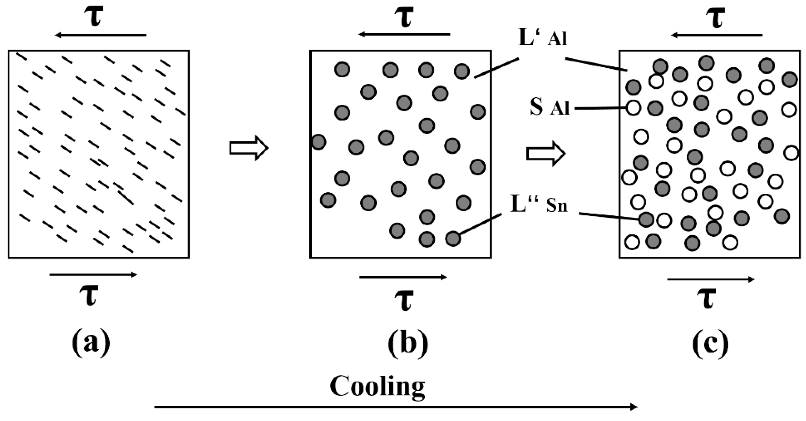
Rheo-mixing process is a process for immiscible alloys, aiming to use semi-solid principle to create a uniform microstructure from immiscible systems [99,100]. As shown in Figure 6, the semi-solid slurry with fine and spheroidal morphology is used to increase the system viscosity to postpone the agglomeration of finely dispersed immiscible phase before solidification, which results in the formation of immiscible phase in the finished products. The rheo-mixing starts from the initial stabilization in the melt by applying an intensive shear to break and disperse the liquid in a homogeneous state at the predefined temperature above the monotectic reaction temperature. The fine liquid dispersion is continuously stabilized by further shearing at the temperature below monotectic reaction temperature in order to create a semi-solid slurry. The viscosity of the semi-solid slurry is sufficiently high that the Stokes’ and Marangoni motions are no longer capable of producing coarse separation in the subsequent solidification. The principle of rheo-mixing has been demonstrated on Ga-Pb, Zn-Pb and Al-45Sn-10Cu immiscible systems [95,101].

3. Manufacturing Method for Non-Dendritic Slurry and Feedstock

3.1. Mechanical Stirring

Mechanical stirring during solidification was the earliest method for making semi-solid slurry because of involving simple equipment [1,7]. In this process, the liquid alloy is continuously stirred for a predefined time during cooling to a temperature below the liquidus. Mechanical stirring process has been further developed and used to produce the SSM slurry by different developers to directly make semi-solid slurry for near-net shaping. The devices of mechanical stirring can as simple as a stirrer [1], or can be a complicated self-mashing twin-screw mechanism [3].
The vigorous agitation of melt during solidification can be started in the superheated state or in the partially solidified state. The forced convection is responsible for the deformation, shearing or melting of dendritic arms, resulting in equiaxed grains in the liquid matrix. Generally, the use of high solidification rates and high cooling rates together with high shearing rates can produce fine and spheroidal solid particles in liquid matrix [102]. It has been confirmed that the intensive shearing in company with high shear rate and high turbulence intensity is beneficial for the formation of fine primary particles and better distribution of primary phase [103,104]. These grains may be re-melted or undertaken isothermal coarsening due to the consistent temperature in the surrounding liquid. The microstructures are further developed after transferring into die cavity, during which more particles and eutectic will be formed from the remnant liquid [105]. However, this technique usually causes serious problems including the erosion of stirrer, the alloy-stirrer reactivity, gas entrainment, melt contamination by debris and oxides, low productivity, and difficulties of controlling the process at industrial scales [1,106].

3.2. Magnetohydrodynamic Stirring

Magnetohydrodynamic (MHD) stirring process was developed by International Telephone and Telegraph (ITT) in the Stamford, CT, USA, aiming to produce non-dendritic microstructure in the alloys by rotating electromagnetic fields, in which the local shearing is created to break up the dendritic arms during casting [107,108]. As the local shearing is under the melt bottom, gas entrapment and inclusion contamination in the slurry is minimized. The fine grain size can be generated at a level of 30 μm for aluminium alloy. The grain refinement for magnesium alloys is more effective [109]. The MHD stirring process has become the most widely used feedstock production method for thixoforming [102]. A strong fluid flow generated by electromagnetic field can change the grain growth mechanism in the semi-solid mushy zone. The variations of shear rates at different radii are responsible for the formation of equiaxed grains in the liquid matrix. The primary grains will be re-melted to form globular primary phase in the surrounding liquid when it is maintained at the semi-solid processing temperature [110].
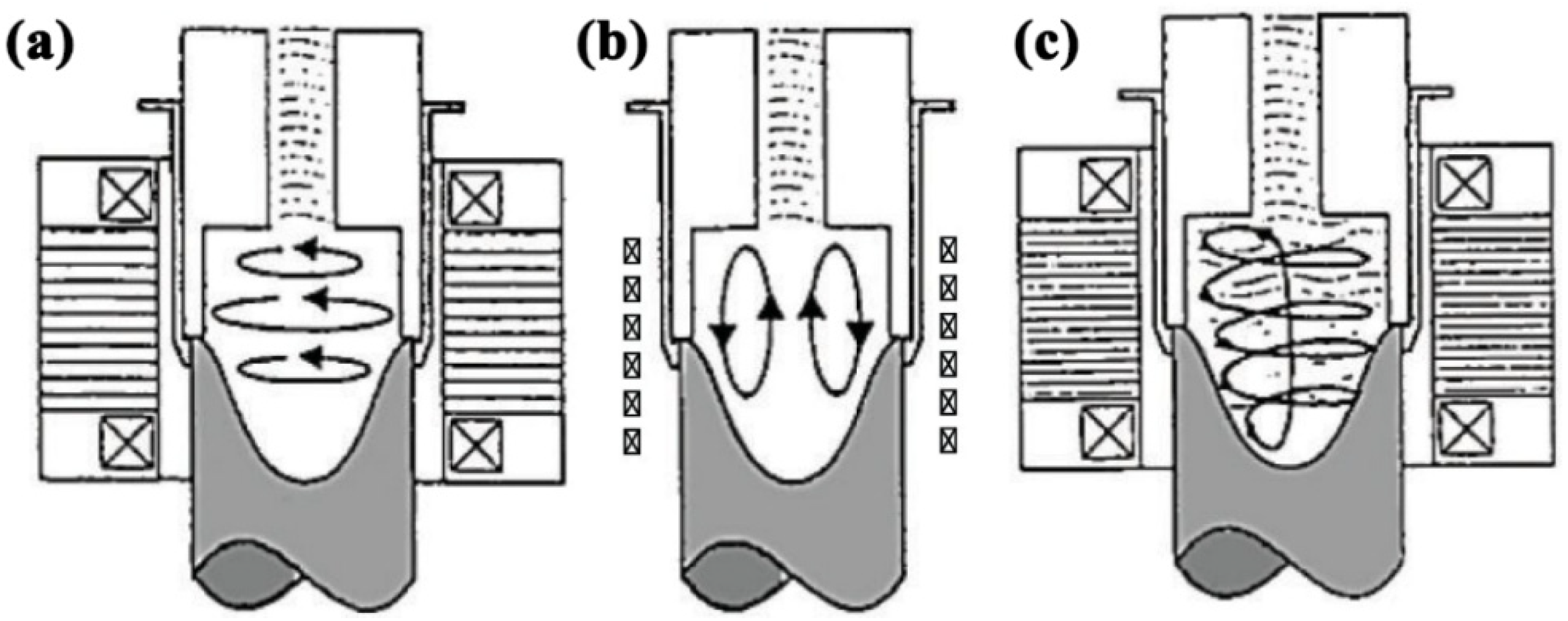
Three modes are capable of creating rotational flow in electromagnetic stirring, which are horizontal agitation, vertical agitation, and helical agitation. Figure 7 shows the schematic of these modes [2,3]. In the vertical mode [111], it is believed that the dendrites in the solidification front undergo a vigorous convection transfer, by which the dendrites are translated from the solidification front to the hotter zone, and the dendritic arms are re-melted at their roots to form globular microstructure. This process is controlled by thermal processing. In the horizontal mode, the motion of the solid dendrites is maintained in isothermal circles. The shear rates are different at different radius, which control the globularization of primary phase [112]. In the helical mode, a combination of the shear at horizontal mode and the convection in the vertical modes is applied to the melt to form non-dendritic morphology of primary phase. In MHD process, solid particles are prone to form rosettes and are not completely round and are not uniformly distributed in the casting billet, which leads to the prolonged reheating times in the subsequent process. As a result, the production cost will be increased. Nevertheless, MHD stirring has been the most effective and most commonly applied method for several decades [113].

3.3. Slope Cooling Plate (SCP)

The slope cooling plate (SCP) technique is the simple non-agitation process [79,114,115], in which the slightly superheated melt is poured down a cooling slope to produce feedstock with a near-globular solid fraction in a liquid matrix. The SCP process was further developed by using a cooling tube [116] and combining with vibration [117]. The process can be continuous through direct combination with a shaping process such as rolling, or can be batch types to collect in a container, which can be used directly for shaping [118]. The key points include the melt with a low superheat at a uniform temperature before entering the cooling slope and the consistency of cooling capability in the slope. The mechanism of forming globular microstructure is based on crystal separation theory. The crystals nucleate and grow on the slope wall and are immediately washed away from the wall by fluid motion [119]. The fluid movement is accelerated by gravity, which removes the crystals on the slope wall and mixes with the superheated melt during flowing. The dendritic arms of primary phase would be re-melted or sheared off to form fine globular microstructures. The process is schematically shown in Figure 8. This process is not desirable for some applications because of gas interruption, contamination by the chemical reactions and oxidation, difficulty in process control, and the consistency of production. The cooling slope can be modified using a vibration [120], which could refine the size of the primary grains; eliminate the segregation in the eutectic phase, and the regional segregation in the squeeze castings.

3.4. Continuous Rheoconversion Process (CRP)

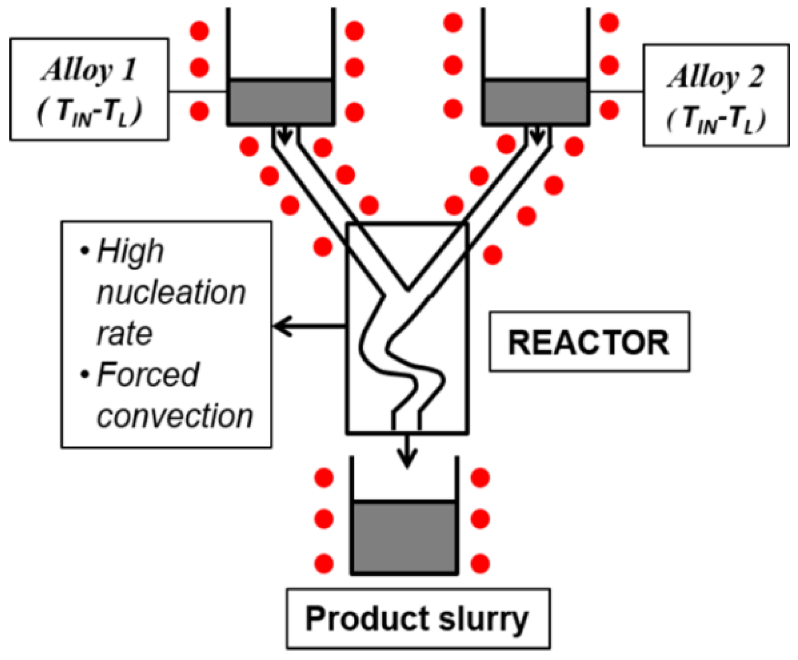
The continuous rheoconversion process (CRP) is developed on the basis of passive liquid mixing techniques through effective control of nucleation and growth of the primary phase in a specially designed reactor, as schematically shown in Figure 9 [122,123]. The mixing of two melts with different compositions (whether grain refined or not) near their respective liquidus temperatures and passive stirring of liquid metal in channels (instead of active stirring via mechanical or electromagnetic means), and the preheated reactor can extract heat, and provide copious nucleation and forced convection during solidification. This leads to the formation of non-dendritic and globular microstructure. During manufacturing, the CRP reactor can be mounted above the shot sleeve. The solid fraction in the slurry can be adjusted through changing the melt temperature and the cooling capability of the reactor. The industrial trials with CRP process has confirmed the capability to cope with various commercial aluminium alloys. The main advantages include the simple process, a wide process window, and the capability of processing a variety of metals and alloys [124].

3.5. Semi-Solid Rheocasting (SSR)

Semi-solid rheocasting (SSR) is a process developed at MIT in 2000 [125], in which a hybrid approach of stirring and near-liquid casting is used. The slurry preparation in this method can be divided into three steps, as shown in Figure 10. The first step is to hold the melt near its liquidus temperature in order to make sure the process is started from a homogenous temperature. The second step is to insert a cooled graphite rod into the melt and immediately stir the melt to rapidly cool down to a temperature slightly below its liquidus for triggering the initial solidification process. The third step is to remove the stirrer from the melt, and cool the melt down to a desirable solid fraction to form SSM slurry, followed by transferring the slurry into the casting machine for shaping the component [126]. It is anticipated that fine dendritic grains are copiously nucleated on the stirrer’s surface when the cold graphite stirrer is inserted into the melt with low superheat. Through stirring the melt below the liquidus temperature, these particles are quickly removed from the stirrer, and are dispersed throughout the melt as fine grains. The primary grains are subsequently re-melted due to the superheat in the surrounding liquid. Therefore, fine particles are developed in the subsequent solidification process, resulting in the formation of non-dendritic and globular primary phase in the microstructure.

3.6. Gas-Induced Semi-Solid Process (GISS)

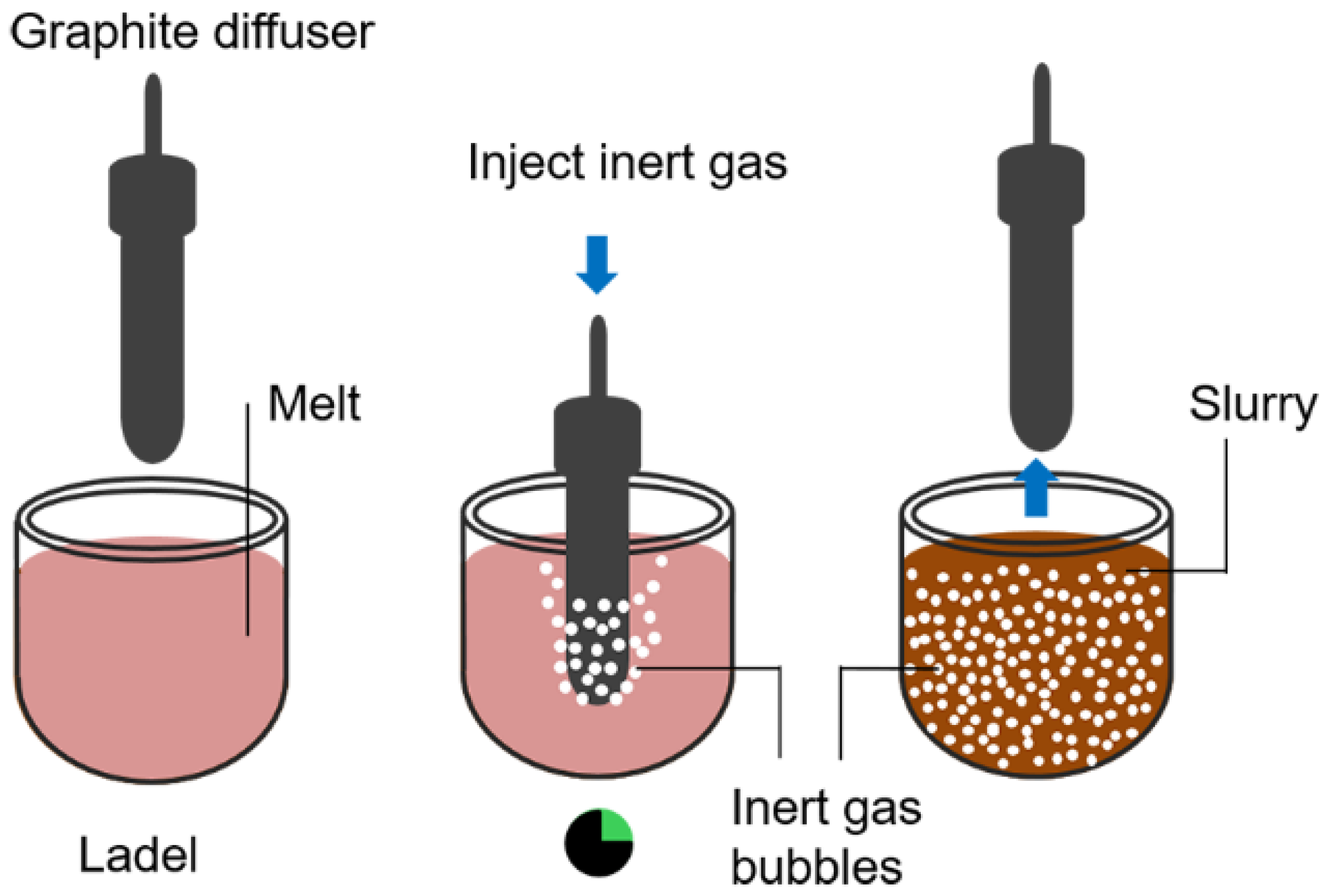
Gas-induced semi-solid process (GISS) is another effective method to provide agitation flowing of gas bubbles in the melt at the initial stages of solidification [127]. It is developed on the exploiting the solidification theory by heat extraction and vigorous local extraction generated from fine gas bubbles. In this process, the gas bubbles are used to stir the melt while it is cooled down to the semi-solid range. The refined gas bubbles can be introduced into the melt through different configurations [128,129]. The preparation of the slurry includes three continuous steps, as schematically shown in Figure 11. The first step is the application of the melt with a low superheat and at a uniform temperature near liquidus temperature. Inert gas bubbles are then generated by immersing a porous graphite diffuser into the melt. Finally, the diffuser is withdrawn after the melt reaches a target temperature with required solid fraction in the slurry, leading to the formation of fine globular microstructure. The mechanism of microstructural evolution can be attributed to the cold graphite diffuser that is immersed in the superheat melt to form numerous nuclei to grow fine dendritic grains on the surface of the diffuser. The gas flow as bubbles enables the solid grains to be mixed within the melt. The solid phase can be partially re-melted due to the surrounding superheated liquid. This process will be balanced in the melt for a predefined time to obtain fine and non-dendritic globular microstructures [130]. The GISS technique is suitable for processing different types of alloys including zinc alloys, aluminium alloys, and magnesium alloys [8,18,125,131].

3.7. Swirled Enthalpy Equilibration Device Process (SEED)

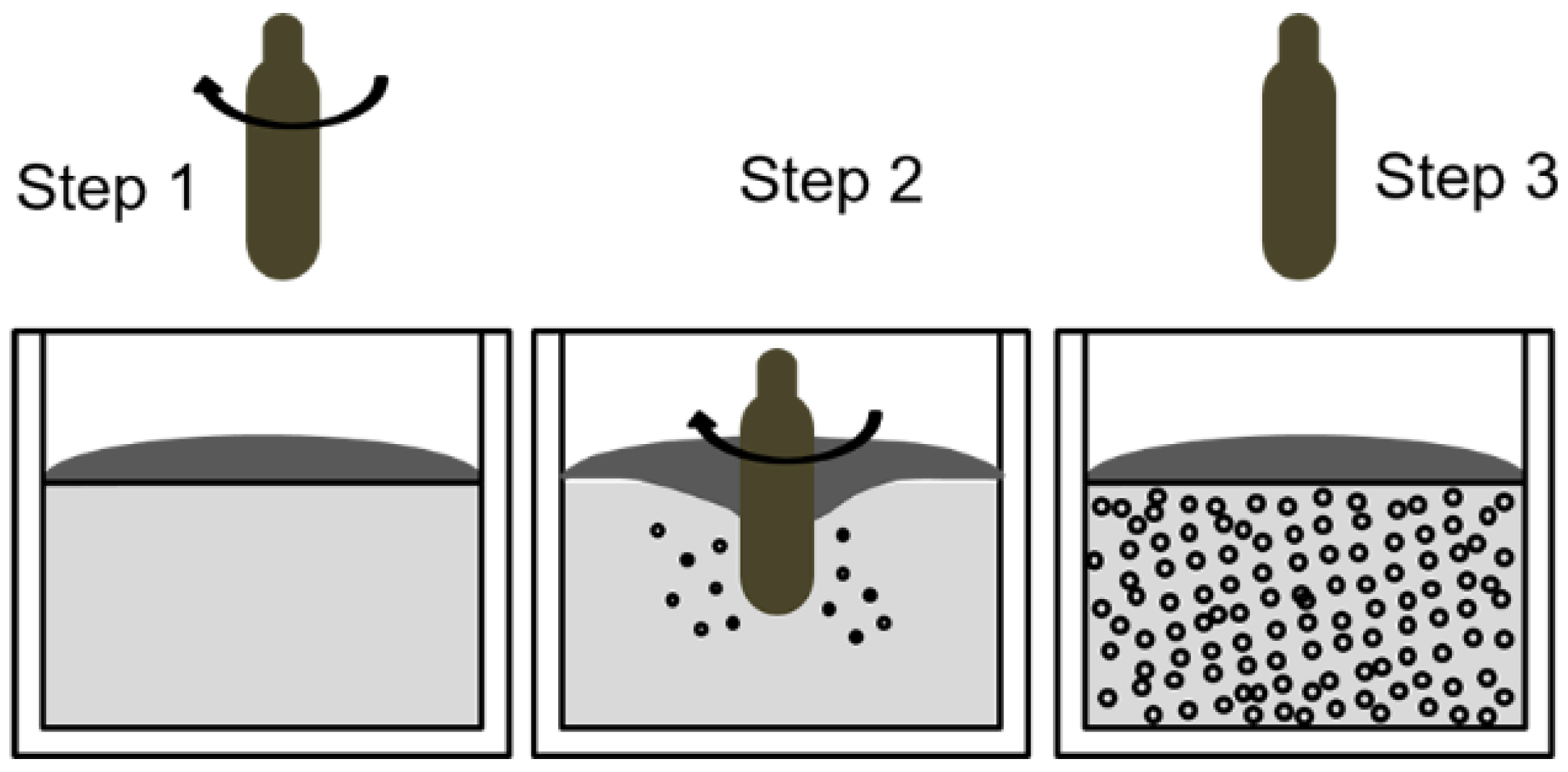
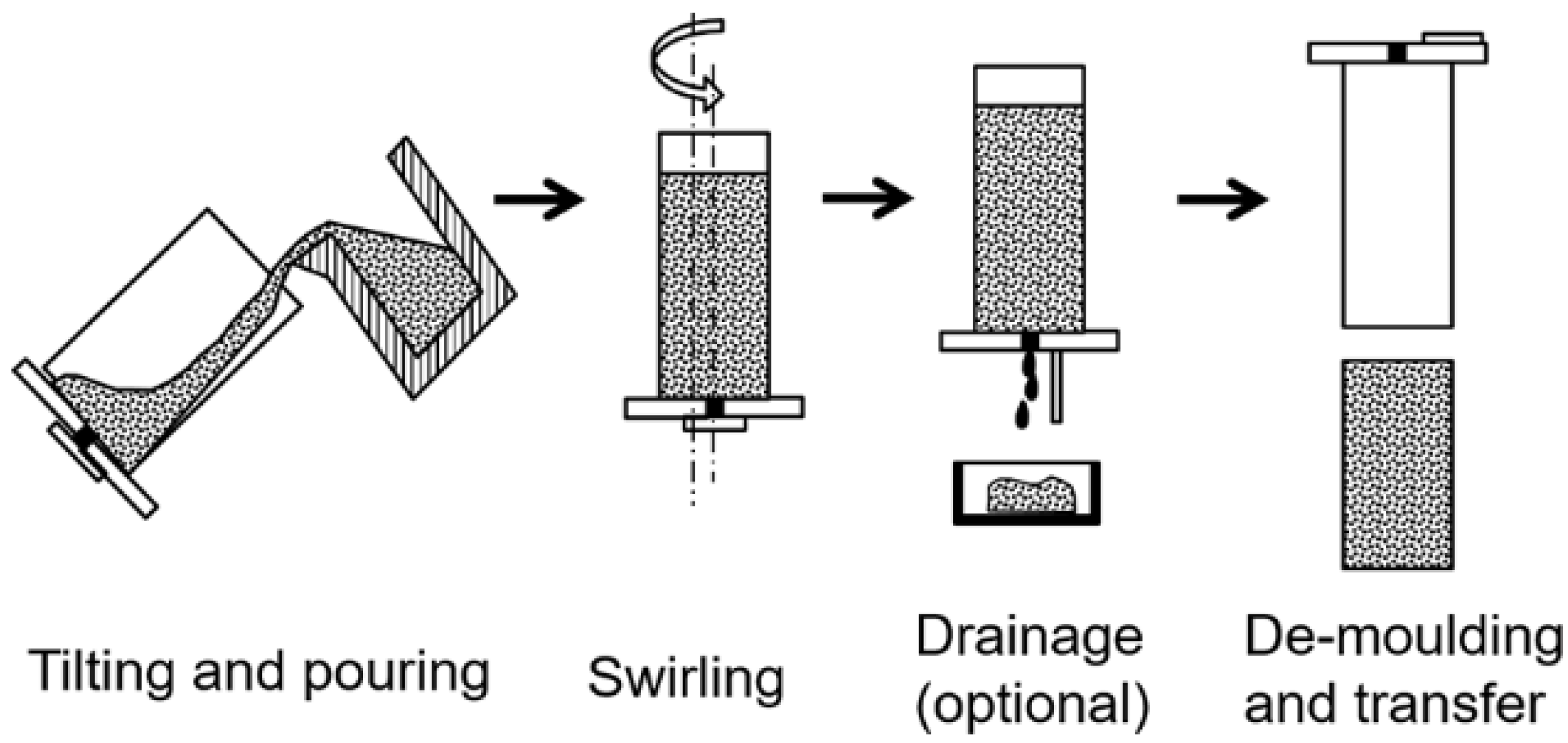
The Swirled Enthalpy Equilibration Device (SEED) process is a technique for feedstock and billet preparation for SSM processing [133]. It is developed on the basis of the eccentric stirring of liquid metal in a metallic container while it is cooled to a semi-solid processing temperature. The employment of eccentric stirring is to regulate the temperature distribution within the semi-solid slurry. The slurry preparation can be described in a continuous three steps, as shown in Figure 12. The first step is to pour a melt with low superheat and a uniform temperature distribution into a container vessel. The thermal mass of the container is designed to be sufficient to solidify the melt to a specific solid fraction within a predefined period. In the second step, the container and the melt are rotated to offer convection. The swirling action assists in the generation of solid phase. In the optional third step, the excess liquid is then drained under pressure to produce semi-solid slurry. In this process, the suppression of growing the dendritic arms in the microstructure is performed without utilizing special heating equipment or specific insulation [134]. Therefore, this method may be cheap and ideal for making small size billets [8,127,135,136].

3.8. Chemical Grain Refinement

Chemical grain refinement is a non-agitation process for producing semi-solid slurry, which can be an additional step in the semi-solid processing, or can be a batch type manufacturing of slurry for shaping. It is essentially applied to the specific alloys, such as by adding a Ti-B master alloy to Al alloy melt in order to promote equiaxed growth for the primary phase [137], or by adding a Zr-containing master alloy into Al-free Mg alloy melt to promote spheroidal growth of primary phase at semi-solid processing temperatures [138]. Obviously, it is not applicable for the alloys that cannot be grain refined by foreign particles. The heterogeneous nucleation suppresses the dendritic growth and promotes the formation of equiaxed and fine grains of primary phase in microstructures. The particle sizes could be around 100 μm for primary aluminium phase and around 50 μm for primary magnesium phase. This can be a good option for the inexpensive production of semi-solid slurry for semi-solid processing. However, it is not easy to be used alone and the processing windows are very tight. This method is suitable only for the certain alloy systems that can be grain refined by nucleation agents.

3.9. Liquidus and/or Sub-Liquidus Casting

Liquidus casting and/or sub-liquidus casting was developed as a low-cost alternative non-agitation method, in which a melt without superheat is poured directly into the die or mould [139]. Two conditions are necessary when casting ingots for thixoforming: one is that the melt is near the liquidus and at a uniform temperature distribution, and the other is that the melt is rapidly solidified under high cooling rates in the mould to affect the morphology of primary grains [140,141]. For thixotropic feedstock production of A356 alloy, low superheat casting into an appropriate mould is capable of making non-dendritic microstructure after reheating the feedstock into a semi-solid state with subsequent shaping.

3.10. Ultrasonic Vibrations (UV)

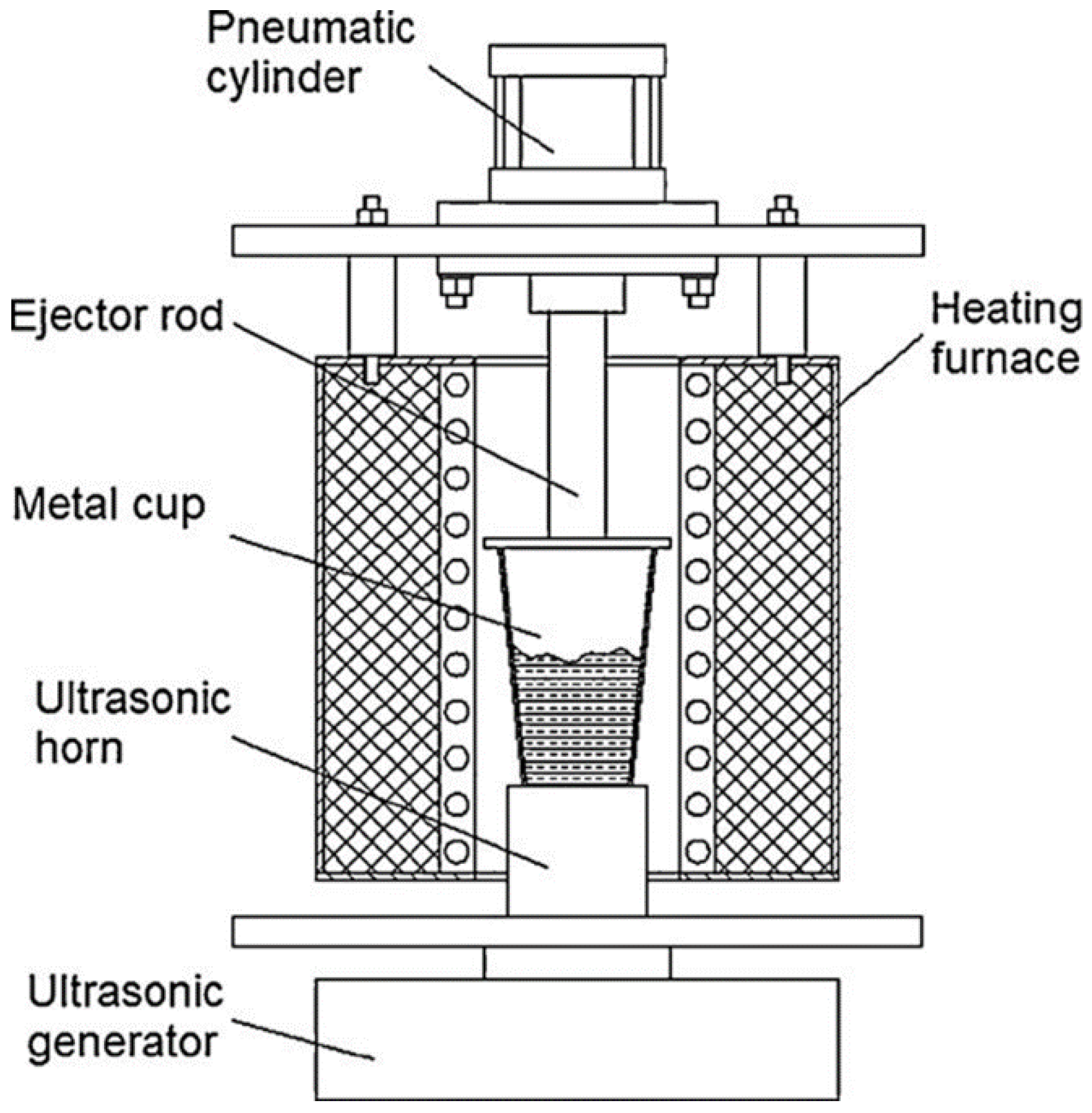
Ultrasonic vibration (UV) can be employed in semi-solid process to prepare semi-solid slurry. The principles of UV method can be illustrated in Figure 13 [142]. The high-power ultrasonic vibrations can increase the number of solidification nuclei during solidification. Cavitation and acoustic streaming are two basic physical phenomena to cause dendrite fragmentation induced by ultrasonic vibrations [143]. Cavitation is associated with the pressure fluctuation to form, grow, pulsate and collapse the tiny bubbles in melt processed by ultrasonic Steady-state acoustic streaming in the melt initiates propagate the high-intensity ultrasonic waves formed inside the melt. Both cavitation and acoustic streaming lead to vigorous mixing and thus homogenizing the melt [137]. Wu, et al. [144] found that numerous nuclei and globular particles can be formed in the Al-Si alloy melt when applying ultrasonic vibration in semi-solid slurry [145]. Jian, et al. [146,147] evaluated the effects of ultrasonic vibration on the solidification behaviour of aluminium alloy A356 melt. The ultrasonic vibrations are able to reduce the mean grain size, decrease the variation of phase distribution and lessen the segregation and improve the homogeneity for composition and microstructure. Qi, et al. [148] pointed out that ultrasonic vibration can not only refine primary α-Al and eutectic phases, but also improve the morphology and distribution of β-Al5FeSi phase for Al-Si-Fe-Mg-Cu-Zn alloy during the preparation of semi-solid slurry.

3.11. Shearing-Cooling Roll (SCR)

The Shearing-Cooling Roll (SCR) process is a liquid-state process for producing the semi-solid feedstock. The principle is shown in Figure 14 [149]. This process applies shearing to the melt at a uniform temperature near liquidus. Shear is created by rotating the roll against the stationary cooling shoe cavity, in which the melt is steadily cooled by the static shoe and the rotating roll. The shear forces generate semi-solid slurries with globular microstructure [150]. It is understood that there are nucleation and growth processes for dendritic primary phases, when the melt is cooled at the contact surface of the roll-shoe mechanism. The shear can crush and disperse the solidified grains into the melt to form equiaxed or spheroidal grains during solidification at high solid fraction. In the SCR process, the high solidification rates and high shearing rates can produce the formation of fine and spheroidal particles in the microstructure [149].

3.12. Stress-Induced and Melt-Activated Process (SIMA) and Recrystallization and Partial Melting (RAP)

The Stress-Induced and Melt-Activated (SIMA) and the recrystallization and partial melting (RAP) are solid state processes for making feedstock for semi-solid processing [151]. Briefly, these techniques rely on reheating the plastically deformed alloy into the semi-solid state. The plastic deformation can occur at a temperature above its recrystallization temperature for the hot working in SIMA process, followed by cold working at room temperature to store the energy for the subsequently partial re-melting. When the alloy is heated to a semi-solid state with uniform temperature, the non-dendritic and spherical solid particles can be formed within the liquid matrix. The SIMA process was modified to that the initial deformation occurs below the recrystallization temperature during cold working, which was named as RAP method [152,153]. Figure 15 shows the difference between SIMA and RAP. Clearly, the SIMA is hot working above the recrystallization temperature and the RAP is warm working. Therefore, SIMA usually requires an intermediate additional cold work step and RAP is limited to use in the smaller billet size because it is difficult to introduce uniform deformation across the cross section for large billets, which is essential for successful thixoforming with a uniform spheroidal microstructure. In both processes, the partial re-melting of pre-deformed material is essential for forming the non-dendritic microstructures. The size of the globular solid particles has a direct association with the heating rate and the plastic deformation. The solid particles can be as small as 30 μm. For effective application, the critical processing parameters include the amount of plastic deformation, reheating temperature, and the duration of heating. The advantages of these routes are that many alloys are supplied in the extruded or rolled state and the spheroids tend to be more rounded for providing the better flow and formability [154].

3.13. Spray Casting

Spray casting is a process using a gas jet to deposit liquid metal droplets and semi-solid particles onto a shaped substrate. Despite no agitation in the process, but high cooling rate is expected during processing, which leads to form grain size usually less than 20 μm [155,156]. Generally, this technique is considered as an expensive method. However, it is suitable for the thixoforming of high melting point alloys such as super alloys and steel [157,158].

3.14. Direct Thermal Method (DTM)

Direct Thermal Method (DTM) is a non-agitation process to make semi-solid slurry [127,159] deom an alloy with low superheat. Usually the melt is poured into a cylindrical metallic mould and cooled by mould that has very low thermal mass but high thermal conductivity to reach a steady semi-solid state. Owing to the heat matching between the alloy and the mould, the alloy can be pseudo-isothermal hold during solidification. Generally, the mould is made by copper tubes with metal base, which can produce very low rate of heat loss to the environment. Initially, the alloy is subjected to a rapid cooling, leading to a high rate of nucleation. After a short time of holding, spheroidal or globular primary phase can be achieved in the microstructure [160]. This method is a low cost and good for small billet but with a limitation on the size of the billet.

3.15. Direct Partial Re-Melting (DPRM)

The Direct Partial Re-melting method (DPRM) is a solid state process to produce a non-dendritic microstructure especially for high-melting-point metals [161,162]. The feedstock from the as-received state without any special treatment can be directly reheated to the semi-solid state through partial re-melting process [163]. This process provides a wide range potential for high temperature alloy to form thixoformable microstructures [58,164].

3.16. Rapid Slurry Forming (RSF)

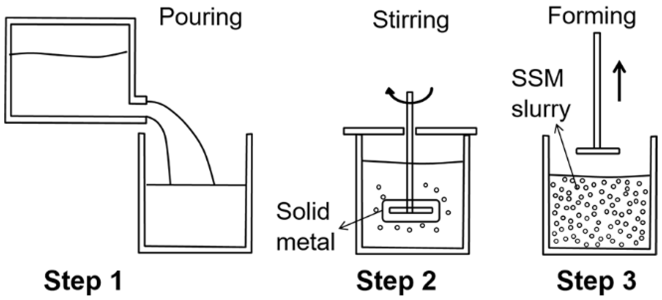
Rapid Slurry Forming (RSF) method is a technique relying on the introduction of a specified amount of solid alloy into the melt to form semi-solid slurry. The inserted metal serves as an internal chill and a stirrer during solidification [165,166], as shown in Figure 16. The nuclei can crystallize at the surfaces of the cold solid alloy during mixing process. The solid grains are immediately dispersed into the melt by the centrifugal force. The melt is cooled to semi-solid state when the insert is melted. The advantage is that the solid fraction of primary phase at 20 to 30% can be quickly obtained with a fine globular structure for retaining the high fluidity of suspension [8,167,168].

4. Evolution of Non-Dendritic Microstructural in Semi-Solid Processing

Processability of semi-solid alloys are affected by the size and morphology of primary particles as well as liquid fraction [169,170,171], so a sufficiently expanded solidus-liquidus interval and optimal liquid/solid ratio of the metal slurry are required traditionally. The microstructural evolution in conventional solidification forms dendritic microstructure, which has been understood to include crystallization, solute redistribution, ripening, inter-dendritic fluid flow, and solid movement. In SSM processing, the spheroidal primary phase is formed during solidification, which is unique in comparison with the dendritic primary phase formed in conventional solidification. According to the processes summarized in above section, the microstructural evolution can be basically divided into two routes: liquid route and solid route. For the liquid route, the non-dendritic primary phase can be formed by dendrite fragmentation [1,4], in which four possibilities including the arms breaking off at their roots due to shear forces, the arms melting at their roots, dendritic arms bending, or spheroidal growth. Additionally, isothermal coarsening is always a concern for the microstructural evolution. For the solid route, the feedstock with equiaxed microstructure is essential because of the fact that the deformed material is recrystallized when it is heated above solidus temperature and the liquid tends to form and penetrate the grain boundaries.

4.1. Microstructural Evolution under Shear (Forced Convection)

The early works have confirmed that the primary solid phase in the semi-solid state has rosette morphology when Sn-Pb alloys were studied using rotational rheometers [101]. With prolonging the time of stirring, the rosette particles change to spheroidal morphology containing entrapped liquid by a ripening process. The increase of shear rates accelerates the morphological transition and reduces the amount of entrapped liquid inside the solid particles. There are several mechanisms proposed for the formation of globular primary phase.
The mechanism of mechanical shear was proposed by Vogel, et al. [172] for the dendrite arm fragmentation to account for grain multiplication. The schematic diagram for this mechanism is illustrated in Figure 17 [173]. It is suggested that the shear force from melt stirring can cause dendrite arms bend plastically, which subsequently introduce large misorientations into the dendrite arms to form ‘geometrically necessary dislocations’. At elevated temperatures, these dislocations are rearranged to form high angle grain boundaries (HAGBs) through recrystallization. The grain boundary is greater than twice of the solid-liquid interfacial energy, so the HAGBs can be wetted by liquid metal easily and result in the detachment of dendrite arms. Ji, et al. [174] investigated the effect of shearing on the dendrite fragmentation of a Sn-15 wt% Pb alloy. It is suggested that the liquid melt initially penetrates into the bent dendrite arms, large angle grooves can be subsequently formed along grain boundaries, leading to the formation of dendrite fragmentation. Although numerous observations have been reported for the dendrite arm bending to support this mechanism, a high proportion of low angle grain boundaries (LAGBs) in the rheocast samples has also been found [175]. Therefore, more evidence is needed to confirm whether this theory is suitable for LAGBs.
The work done by Mullis, et al. has confirmed the possibility of forming rosette by growth induced dendritic bending in a shear flow [176,177]. To understand the free boundary model of dendritic solidification, the effects of fluid flow on dendritic growth was studied for the orthogonal flow to the principal growth direction. the result shows that the dendrite bends into the flow due to thermal/solutal advection, and growth rate has the more pronounced effect than the flow velocity on the rate of bending.
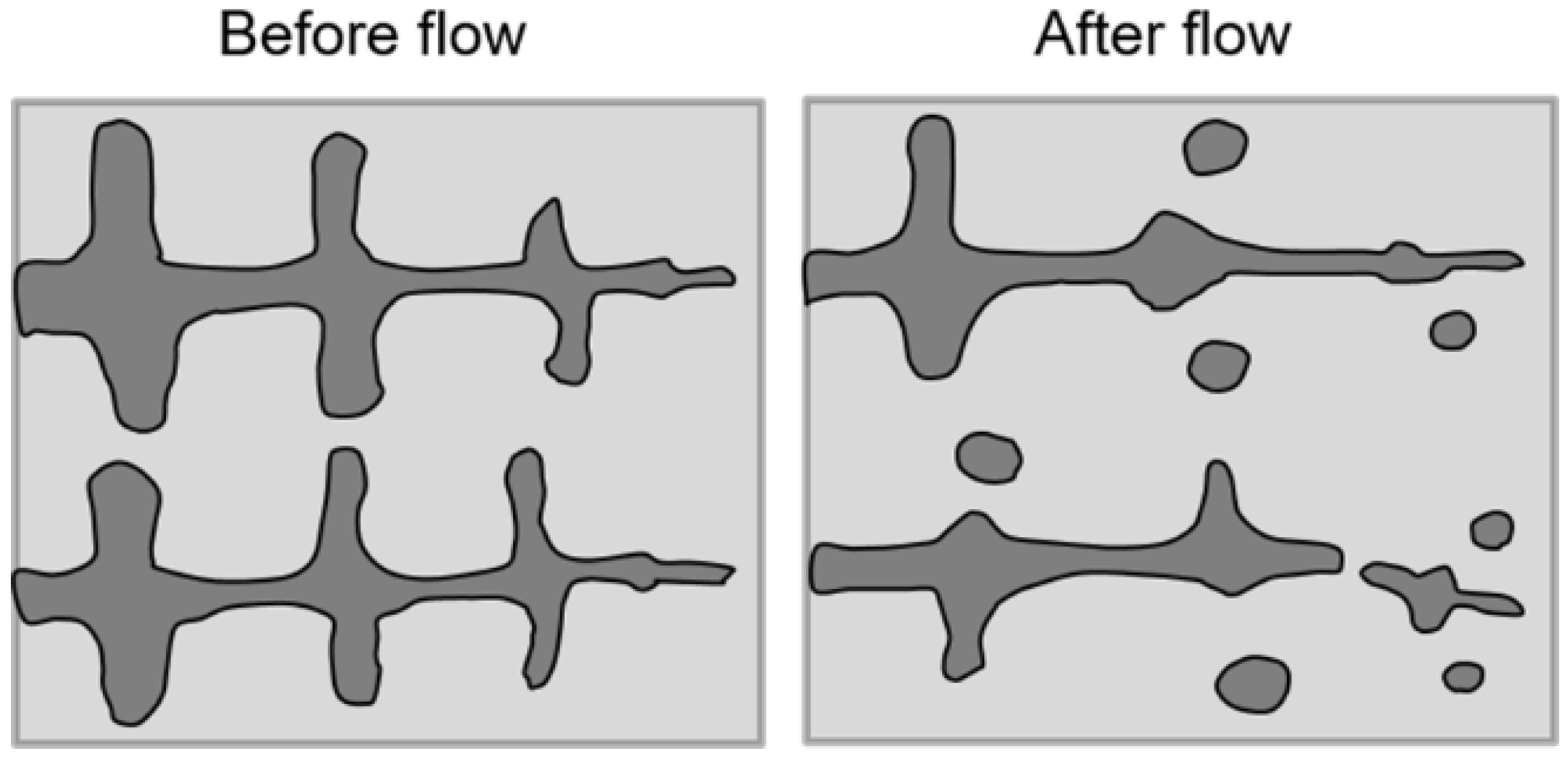
Another mechanism proposes that solute enrichment and thermosolutal convection near the dendrite root detach secondary or tertiary arms, creating high density of solid grains [178], as shown in Figure 18. Flemings, et al. [179] suggested that significant temperature disturbances in a molten metal can be provided by vigorous stirring and localized rapid cooling, and it is helpful for the re-melting and separation of dendrite arms from a “mother” dendrite. Hellawell, et al. [180] proposed that the secondary dendrite arms can be detached at their roots through re-melting because of the solute enrichment and thermosolutal convection. Vigorous stirring can cause intensively forced convection and destroy the stable diffusion fields for continued dendritic evolution, then smooth and rounded shapes are eventually obtained in solidification. Figure 18 illustrates schematically the grain multiplication through this mechanism. Jackson, et al. [181] proved that the high solute concentration in the boundary adjacent to the primary phase will decrease the local melting temperature owing constitutional supercooling. Wang, et al. [108] increased solute Gd of Mg-RE alloy to over 9 wt%, resulting in fine and spherical primary Mg phase by dendrite arm root re-melting in preparing semi-solid Mg-RE alloys slurries. Ruvalcaba, et al. [182] observed local solute-enrichment during solidification of an Al-20 wt% Cu alloy using synchrotron X-radiation microscopy, and found that local fragmentation of dendrite arms is initiated by transient growth conditions. The solute is transported into the mush zone due to gravity-induced liquid flow, which occurs naturally during solidification.
The spheroidal growth was proposed by Ji, et al. [183,184] after understanding the role of intensive shear and the effect of turbulence flow on the solidification to form primary phase. The intensive shearing and the turbulence flow can cause the following changes: (1) the formation of uniform temperature and composition fields in melt, (2) the improvement of the heterogeneous nucleation and growth throughout melt, (3) the decreasing thickness of thermal and solute diffusion boundary layer at solid/liquid interface, (4) the reduced constitutional undercooling significantly, and (5) the increasing stability of the solid/liquid interface at a thinner level [185]. Therefore, the nucleation and growth of primary solid particles in the melt can be very different from the traditional approaches, which enhance the thermal transportation, the mass transportation and thin the ever-renewed solid/liquid interface. Because the fluctuations of temperature and composition fields are reduced significantly, most of atomic clusters can survive in the uniform temperature field once they become nuclei, leading to an significantly increased number density of nuclei in melt. At the same time, the intensive shear can produce a more uniform distribution of atomic clusters owing to a better dispersion throughout melt, which instantaneously promote the nucleation and growth throughout the whole melt, increasing the effective nucleation rate and uniform growth of primary particles [102]. Li, et al. [186] studied the morphological evolution of succinonitrile −5 at% water with stirring during solidification by in situ observation. They pointed out that the formation and the growth of globular crystals originate from the direct nucleation and the stirred melt when the alloy is cooled with simultaneous stirring from a temperature above the liquidus or between the liquidus and solidus.
As summarized by Ji, et al. [183], the intensity of shear is capable of altering the fluid flow characteristics in the melt. At low shear rate, the flow is essentially laminar, which may be sufficient to rotate the dendrites and cause bending of dendrite arms. As a result, the rosettes can be formed. However, under this condition, although the thickness of diffusion boundary layer around growing dendrites has been changed, the detachment of dendrite arms may not happen until the shear rate reach a certain level. The eventual morphology of primary phase will be maintained as rosette. At high shear rates, the turbulent flow is generated. The liquid can penetrate into the inter-dendritic region change the solidification patterns as solutes transfer away from the secondary dendrite arms. In this case, the detachment of dendrite arms can occur. When the shear rates are sufficiently high, the ever renewed interface between solid and liquid will promote the formation of spheroidal particles. The morphological transition from initial dendrite to final spheroidal structures via rosette with increasing the shear rate and the intensity of turbulence is shown in Figure 19.
The growth from the nuclei to the final solid particles can be actually divided into two sequential stages. The first stage is the growth of the nuclei during continuous shearing and cooling to a temperature corresponding to the desired solid fraction. As mentioned above, the driving force at this stage for growth comes from the temperature drop, and the growth rate is usually high due to the favourable thermodynamic and kinetic conditions. The second stage is the growth during isothermal shearing at a fixed semi-solid temperature. The driving force is supplied by the tendency for reducing the solid/liquid interfacial area governed by Gibbs—Thompson effect. Sannes, et al. [187] investigated the microstructural evolution of semi-solid ZE33 magnesium alloy at different solid fractions, and they found that the coarsening kinetics obeys the Lifshitz—Slyozov—Wagner (LSW) theory [188,189]. They also found that the coarsening rate increases with decreasing solid fractions, and pointed out that coalescence ripening plays major role to the microstructural coarsening at high solid fraction in the semi-solid state, while Ostwald ripening is the dominant mechanism for microstructural coarsening at low solid fraction. Ji, et al. [190] studied the isothermal coarsening under low shear rate for the semi-solid slurry of AZ91D alloy with initially fine and spherical particles that is produced by high shear rate. As shown in Figure 20, there is a domain coarsening process under low shear rate, in which these fine and spherical solid particles in the semi-solid slurry become coarse obviously with decreasing particle density, while the solid fraction, particle shape and agglomeration level of solid particles remain constant. Besides, both the coarsening rate constant and the exponent agree well with the calculated value based on the classical LSW theory.

4.2. Microstructural Evolution by Grain Refinement

Qian [129] investigated the growth of primary phase in the refined magnesium alloys and found that the primary grains can grow up from a properly refined alloy melt to form spheroidal morphology without agitation. A wide range of solid fraction up to more than 50% can be obtained through effective control of nucleation and growth by grain refinement. The spherical primary particles are formed by the combination of both dissolved and undissolved zirconium, which increase the nucleation rates under a small undercooling. When all conditions required for the Mullins—Sekerka stability analysis are satisfied, the Mullins—Sekerka stability criterion for spherical growth can be used to interpret the formation of globular microstructure. Adding erbium to modify A356 Al alloy, spherical primary α(Al) grains can be obtained in semi-solid state produced by serpentine channel technique, and more Er additions lead to uniform distribution and finer size of spherical primary α(Al) grains [191].
In addition, the sharp chilling effect of serpentine channel process on melt can promote heterogeneous nucleation, and fine-grained semi-solid alloy can also be obtained by prompting the initial solidification nucleation [192]. Qi, et al. [193] adopted distributary-confluence channel (DCC) technology to fabricate semi-solid slurry of aluminium and magnesium alloys, in which the melt went through multiple chilling channels and accumulated together finally. At last, fine primary grains obtained due to the high nucleation rate by melt chilling and intensity melt convection. Using the DCC technology, refine and spheroidize primary α(Al) grains can also be obtained in a semi-solid 6061 Al alloy [194], and it was proved that the nucleation rate of primary grains is effectively increased via increasing the bend number and decreasing the bend diameter.

4.3. Microstructural Evolution during Partial Re-Melting

The microstructural evolution through partial re-melting to semi-solid temperatures can be divided into four steps [1,2,3,4] known as “(1) recovery, recrystallization and structural separation; (2) coarsening of solid grains; (3) spheroidization of solid grains; and (4) coarsening of spherical grains.” according to reference [195].
In the first step stage, the microstructural change mainly involves in recovery, recrystallization, and structural separation owing to the heating operation [196]. Considering the fact that sub-grain boundaries form by the climbing or cross slipping resulting from joined vacancies and rearranged dislocations, grains with high dislocation density are easily replaced by new sub-grains with less dislocation density. Because the holding temperature of alloy billets is higher than the eutectic temperature, partial re-melting also occurs when a portion of solid phases is melted [197,198]. With the increase of heating time, the liquid is formed and becomes greater gradually to create isolated solid grains. These grains grow and coarsen continuously under isothermal heating. It is commonly known that the growth and coarsening of the solid grains in semi-solid state are controlled by coalescence and Ostwald ripening. During the growing and coarsening of the microstructure, atoms of the solid material diffuse from regions with high curvature to regions with low curvature points, providing the driving force for spheroidization of solid grains [199]. As long as the grains are not spherical at semi-solid processing temperatures, the spheroidization process occurs to maintain the minimum surface energy, during which the grain numbers per unit volume remain un-change.
Following this stage, smaller grains are melted in favour of the larger grains, and the numbers per unit volume are reduced. The grain coarsening follows Ostwald ripening mechanism according to the LSW theory [151]. Loue and Suery [200] studied the microstructural evolution of A357 alloy during isothermal holding after partial re-melting, and found that the number density of initially formed globular particles decreases with increasing the isothermal holding time, but that initially formed dendritic structures remains fairly constant. Also, the coarsening kinetics of solid particles is accelerated under longer solidification time and smaller initial grain size. Blais, et al. [201] investigated the effects of initial particle morphology in semi-solid alloy on the coarsening behaviour. During isothermal holding in the semi-solid state, the solid particles always evolve towards a spherical morphology regardless of the initial morphology. Moreover, according to the Doherty theorem [202], the coarsening rate accelerates when the solid fraction (fs) is higher than 0.6. However, the research carried out by Manson—Whitton, et al. [152] showed opposite results in the case of spray formed Al-4%Cu with higher solid fractions (fs ≥ 0.7). Therefore, the solid-solid contacts affect the morphology of the primary solid phase during coarsening. For the solid fractions greater than the transition value at 0.7, the coarsening rate constant (k) decreases as solid fraction increases. In general, Ostwald ripening is the dominant mechanism for solid particle growth at high liquid volume fractions i.e., high heating temperatures and long holding times in semi-solid state. This mechanism is less effective in particle growth but has a significant effect on the spheroidization of solid grains. In contrast, the coalescence growth mechanism occurs for semi-solid alloys at a small amount of liquid fractions, which is more effective in grain growth but has only a minor effect on the spheroidization process [203,204]. The solid grains are readily in contact with one another at a relatively high solid fraction (early stages of heating operation), and dominant growth mechanism in the coarsening of the solid grains obeys the coalescence mechanism. Further increase of the holding time decreases the solid fraction in semi-solid alloy, and Ostwald ripening mechanism becomes more effective in the process of grains coarsening. Therefore, it is expected that spheroidization and further growth of solid grains are governed by the two competing mechanisms during re-melting process.
High entropy alloys (HEAs) containing different solution phases have high melting temperatures with solidification intervals, making them potential candidates for semi-solid processing [205,206,207]. For example, Rogal [208] recently studied thixoforming of CoCrCuFeNi HEAs. The globular microstructure can be obtained by the recrystallization and partial re-melting method using a temperature at 1150 °C and 1340 °C. The microstructure of the thixo-cast alloy consists of two face-cantered cubic solid solutions: one in the form of globular grains, containing near equiatomic concentrations of Co, Cr, Fe and Ni, and the other, enriched in Cu, homogeneously distributed around grains. For the CrCuFeMnNi HEAs, increasing the Cu content can cause an increase of low melting FCC1 phase and a decrease of FCC2 phase, and Cr-rich BCC phase can be formed during solidification. Dual face-centred cubic (FCC) CoCrCu1.2FeNi was also chosen to fabricate semi-solid feedstock by SIMA [209], in which Cu-rich FCC1 phase was liquid in semi-solid state, and both FCC1 and FCC2 phases recrystallized during heating. Finally, FCC2 phase coalesced, grew up and spheroidized with a low coarsening coefficients in semi-solid range.

4.4. Microstructural Evolution in an Inclined Cooling Surface

Microstructural evolution involved in the inclined cooling surface is a complex combination of heat-fluid flow-mass transfer in the liquid and/or solid state, which may include a combination of shear and re-melting associated with the slope cooling process. As shown in Figure 21, the heat transfers between the contacting melt and the inclined surface, and the shear stress acted on the melt as result of gravity force are critical parameters to change the microstructure [210]. When the melt with initial low superheat is poured on the cooling slope, it forms an ‘elliptical impact zone’ where material is spread and cooled [211,212]. The impact zone on the cooling slope is anticipated to be the principal source of nuclei [23,213]. Solidification begins on the cooled surface when the melt temperature drops below the liquidus temperature. During the movement of the melt along the slope, the gravity force generates shear stress and varies shear rates in the melt, leading to the detachment of solid primary phase from the cooled surface, which are subsequently mixed with the melt away from the cooled surface, and the solid phase is immediately reheated to a temperature above the liquidus temperature. As the solute segregation at the solidification front takes place during grain growth in an alloy, the solute variation in the melt can cause nucleating crystal to detach from the inclined cooling surface. Comparing with the solute content at cooled surface, there is higher solute content in the region of roots of the crystal owing to the segregated solute atoms to disperse in the liquid, which leads to interfacial undercooling and lower growing rate in the local region. Consequently, a necking is developed by the decelerated growing rate, then the necked crystal can be detached from the cooling surface [214]. As the pouring continues, the formed crystals are continuously detached from the cooling surface and join the melt downward. It was also pointed out that the temperature variation results in the detachment of dendrite arms. Studies have been performed to examine the effect of length and angle of slope plate on the morphological evolution of the grains [114,215]. However, it can be argued that the nucleation of the primary phase may also take place throughout the melt owing to shearing and cooling the melt below solidification temperature. Taghavi, et al. [216] reported the microstructural formation of three layers when the melt flow over the inclined surface. The bottom layer connected to the surface of the inclined surface is a solid layer containing the primary solid phase. The middle layer is a semi-solid layer containing the growing primary solid phase and the melt. The top layer contains the molten alloy in which the heat transfer rate is higher than that in the middle layer. The heat and solute would be transported simultaneously in this process, which result in the non-dendritic morphology transition of primary phase.

5. Microstructural Evolution of Binary Eutectic Alloy under Forced Convection

Although the semi-solid principle has been reasonably understood for the alloys solidified in a temperature range [169,170], it has found the eutectic alloys and pure metals that solidify with a solid-liquid fraction ratio during thermal arrest at a fixed temperature, which can also be processed to form semi-solid slurry [169,217,218,219,220,221], as shown in Figure 22. This confirms that semi-solid slurry can be formed by controlling the temperature, and/or by controlling the time of solidification process. The nucleation and growth of eutectic alloys under forced convection are different from that in off-eutectic alloys.
In a binary eutectic alloy, two distinct types of nuclei are existed in the melt, and each of them corresponds to one chemical composition. For the conventional eutectic solidification [222], the nucleation events commence at a temperature below the eutectic temperature with the heterogeneous nucleation of one of the eutectic phases on nucleants present in the liquid, and is completed by the heterogeneous nucleation of the second eutectic phase on the first. Under forced convection, the temperature and composition fluctuations are significantly reduced and become uniform and ever-renewable in each part of the bulk melt. Generally, a uniform temperature field is benefit for the survival of crystal nuclei after it is created from the atomic clusters, leading to an increased density of crystal nuclei. For the binary eutectic alloy, the potential nuclei of each phase can be dispersed throughout the bulk melt independently and uniformly when the forced convection is applied below the liquidus temperature. Under the condition with similar density of atomic clusters in the melt, the ever-renewed and uniform temperature and composition fields can reduce or even diminish the suppression effect from one phase to another phase. Therefore, the nucleation undercooling is minimized greatly, and the atomic clusters grow and become nuclei at a temperature close to the equilibrium temperature.
For the eutectic solidification under conventional conditions, two eutectic phases can grow synergistically behind an essentially planar solidification front as it is controlled by boundary diffusion. Traditionally, the solidification of one phase result in excessive concentration of another phase by short diffusion distance laterally. Similarly, the solute atoms rejected ahead of one phase diffuse to the tips of the adjacent lamellae. This diffusion-controlled growth of eutectic solidification leads to a lamellar morphology in the eventually solidified microstructure of eutectic alloys. While forced convection can cause the volume diffusion of solute atoms in the matrix, and the microstructural morphologies of eutectic alloys have become dependent on the convection intensity. A relatively weak shear can only enhance the solute transportation at the solid/liquid interface a little of, but there is little perturbation in this process for the eutectic alloy solidification. Therefore, a weak shear may not entirely destroy the lamellar eutectic growth. It has been proposed that the promotion of solute transportation just varies the interlamellar spacing or the lamellar growth direction in eutectic solidification [223]. It is suggested that the limited solute transportation at the solid/liquid interface may possibly constrain further growth of solid phase, which leads to the coupled format as a short and irregular rod microstructure. When the intensity of shear increases to a moderate level, the solute transportation at the solid/liquid interface increases, and diffusion layer around solid phase reduces, resulting in the formation of coupled particles. Two kinds of eutectic phases are alternatively arranged in the coupled eutectic cell. In this case, one phase may form imperfect spheroidal particles firstly, and subsequently another phase nucleates and grows on the surface of a phase due to the local solute accumulation. The number of coupled particles depends on the imperfect points on the surface of the existing solid particles, which is further determined by the intensity of forced convection. Once the intensity of forced convection increases to a sufficiently high level, both the temperature field and the composition field are extremely uniform throughout the eutectic melt. the solute at the solid/liquid interface is uniformly distributed, and the diffusion layer around the solid phase are significantly reduced and even diminished. As a result, the crystal nuclei of two phases are also distributed throughout the bulk melt uniformly. The particles of prior phase grow and form perfect spheroids with equal growth velocity, and nucleation can occur on the whole surface with equal probability in the uniform composition field. On the other hand, another phase grows independently from the crystal nuclei in the saturated melt as perfect spherical particles. The effect of forced convection on the eutectic alloy can be schematically shown in Figure 23. The same principle should apply to the eutectic alloys containing more than two components. The importance of this finding is that the knowledge of SSM processing as a function of temperature for the alloy with one primary phase is extended to the simultaneous formation of multiple phases in a consistent temperature. Therefore, the parameters to control the formation of solid phases can be obtained by temperature and time. In other words, SSM processing is not only temperature dependent, but also time-dependent. It is also demonstrated by Al-Si eutectic alloy to form semi-solid slurry for rheocasting because the thermal arrest during solidification, induces the decoupled crystal growth between silicon and aluminium under convection [220,224].

6. Summary

After several decades’ development, semi-solid metal processing has been used in industry for different alloys. It is still attracting more interesting in processing new materials, including high entropy alloys, eutectic and purify alloys. Therefore, SSM processing of new materials is one area to be explored in future, in particular for the high value-added materials. Meanwhile, the development of novel alloys should be matched with the technological characteristics of slurry preparation and shaping of semi-solid alloys, aiming to achieve excellent processing or performance properties. Only combining the alloys with the SSM processing can exert its function in microstructural control.
A major advantage of the semi-solid processing comes from the fact that it can achieve a low level of defects in components. During fabrication and forming of semi-solid alloys, gas entrapment and inclusion contamination in the slurry should be minimized. Although present fabrication processes of semi-solid slurry have been optimized greatly, gas entrapment and inclusion contamination can’t be avoided entirely due to intensive disturbance during preparing semi-solid slurries. Comparatively, new rheocasting (NRC) process can yield non-dendritic primary grains without any disturbance in semi-solid state, and it can allow a laminar flow during filling and solidification under a high pressure. Therefore, NRC or other novel processes may be effective technological methods for improving SSM processing and achieve the maximum potential for SSM alloys.
As the cost of manufacturing non-dendritic feedstock for thixoforming is an issue for massive manufacturing, thixoforming may be not very competitive for low cost material such as aluminium alloys and magnesium alloys. However, it is still attractive for making high integrity components that are not capable of making by other processing methods or that are high value-added components. For massive production of aluminium and magnesium alloys, rheocasting is a cost-saving process and competitive for the balance of manufacturing cost and quality. Therefore, the process on slurry-making from the liquid alloy is one of the critical areas. However, the low volume fraction of primary phase in semi-solid slurry may not be desirable option because it may be difficult to achieve obvious improvement of mechanical properties in the components in comparison with that made by high pressure die casting. Therefore, more efforts are required to provide a microstructure comprising high volume fraction of fine and spheroidal particles distributed uniformly in the matrix for subsequent component shaping.

Author Contributions

Conceptualization, S.J.; Draft, Methodology, Investigation and Editing, K.W., X.D. and S.J. All authors have read and agreed to the published version of the manuscript.

Funding

This research was funded by Innovate UK (project No.12182100).

Institutional Review Board Statement

Not applicable.

Informed Consent Statement

Not applicable.

Data Availability Statement

All data are referred to original publications.

Acknowledgments

The contribution of Mingxu Xia from School of Materials Science and Engineering, Shanghai Jiao Tong University for the manuscript is gratefully acknowledged.

Conflicts of Interest

The authors declare that they have no known competing financial interests or personal relationships that could have appeared to influence the work reported in this paper.

References

  1. Flemings, M.C. Behavior of metal alloys in the semisolid state. Metall. Trans. A 1991, 22, 957–981. [Google Scholar] [CrossRef]
  2. Kirkwood, D.H. Semisolid metal processing. Int. Mater. Rev. 1994, 39, 173–189. [Google Scholar] [CrossRef]
  3. Fan, Z. Semisolid metal processing. Int. Mater. Rev. 2002, 47, 49–85. [Google Scholar] [CrossRef]
  4. Atkinson, H.V. Modelling the semisolid processing of metallic alloys. Prog. Mater. Sci. 2005, 50, 341–412. [Google Scholar] [CrossRef] [Green Version]
  5. Winklhofer, J. Semi-Solid Casting of Aluminium from an Industrial Point of View. Solid State Phenom. 2019, 285, 24–30. [Google Scholar] [CrossRef]
  6. Kim, D.H.; Kim, B.M.; Kang, C.G. Die life considering the deviation of the preheating billet temperature in hot forging process. Finite Elem. Anal. Des. 2005, 41, 1255–1269. [Google Scholar] [CrossRef]
  7. Flemings, M.C.; Riek, R.G.; Young, K.P. Rheocasting. Mater. Sci. Eng. 1976, 25, 103–117. [Google Scholar] [CrossRef]
  8. Jarfors, A.E.W. A Comparison Between Semisolid Casting Methods for Aluminium Alloys. Metals 2020, 10, 1368. [Google Scholar] [CrossRef]
  9. Ji, S.; Fan, Z.; Liu, G.; Fang, X.; Song, S. Twin-screw rheomoulding of AZ91D Mg-Alloy. In Proceedings of the 7th International Conference on Semi-Solid Processing of Alloys and Composites, Tsukuba, Japan, 25–27 September 2002. [Google Scholar]
  10. Czerwinski, F.; Zielinska-Lipiec, A.; Pinet, P.J.; Overbeeke, J. Correlating the microstructure and tensile properties of a thixomolded AZ91D magnesium alloy. Acta Mater. 2001, 49, 1225–1235. [Google Scholar] [CrossRef]
  11. Ji, S.; Fan, Z. Extruded microstructure of Zn–5 wt-%Al eutectic alloy processed by twin screw extrusion. Mater. Sci. Technol. 2012, 28, 1287–1294. [Google Scholar] [CrossRef]
  12. Forn, A.; Vaneetveld, G.; Pierret, J.C.; Menargues, S.; Baile, M.T.; Campillo, M.; Rassili, A. Thixoextrusion of A357 aluminium alloy. Trans. Nonferrous Met. Soc. China 2010, 20, s1005–s1009. [Google Scholar] [CrossRef]
  13. Mohammed, M.N.; Omar, M.Z.; Sajuri, Z.; Salleh, M.S.; Alhawari, K.S. Trend and Development of Semisolid Metal Joining Processing. Adv. Mater. Sci. Eng. 2015, 2015, 846138. [Google Scholar] [CrossRef] [Green Version]
  14. Haga, T. Semi-solid roll casting of aluminum alloy strip by melt drag twin roll caster. J. Mater. Process. Technol. 2001, 111, 64–68. [Google Scholar] [CrossRef]
  15. Binesh, B.; Aghaie-Khafri, M. Microstructure and Properties of Semi-Solid Aluminum Alloys: A Literature Review. Metals 2018, 8, 181. [Google Scholar] [CrossRef] [Green Version]
  16. Modigell, M.; Pola, A.; Tocci, M. Rheological Characterization of Semi-Solid Metals: A Review. Metals 2018, 8, 245. [Google Scholar] [CrossRef] [Green Version]
  17. Kapranos, P. Current State of Semi-Solid Net-Shape Die Casting. Metals 2019, 9, 13. [Google Scholar] [CrossRef] [Green Version]
  18. Chang, Z.; Su, N.; Wu, Y.; Lan, Q.; Peng, L.; Ding, W. Semisolid rheoforming of magnesium alloys: A review. Mater. Des. 2020, 195, 108990. [Google Scholar] [CrossRef]
  19. Li, G.; Lu, H.; Hu, X.; Lin, F.; Li, X.; Zhu, Q. Current Progress in Rheoforming of Wrought Aluminum Alloys: A Review. Metals 2020, 10, 238. [Google Scholar] [CrossRef] [Green Version]
  20. Adachi, M.; Sasaki, H.; Harada, Y.; Sakamoto, T.; Sato, S.; Yoshida, A. Method and Apparatus for Shaping Semisolid Metals. Europe Patent EP0745694B1, 8 December 1996. [Google Scholar]
  21. Adachi, M. Characteristics of UBE rheocasting process. In Proceedings of the Japanese Die Casting Association, JD98-19, Yokohama, Japan, 11–13 November 1998; pp. 123–128. [Google Scholar]
  22. Muumbo, A.; Nomura, H.; Takita, M. Casting of semi-solid cast iron slurry using combination of cooling slope and pressurisation. Int. J. Cast Met. Res. 2004, 17, 39–46. [Google Scholar] [CrossRef]
  23. Kaufmann, H.; Uggowitzer, P.J. Fundamentals of the New Rheocasting Process for Magnesium Alloys. Adv. Eng. Mater. 2001, 3, 963–967. [Google Scholar] [CrossRef]
  24. Legoretta, E.C.; Atkinson, H.V.; Jones, H. Cooling slope casting to obtain thixotropic feedstock II: Observations with A356 alloy. J. Mater. Sci. 2008, 43, 5456–5469. [Google Scholar] [CrossRef] [Green Version]
  25. Kopp, R.; Neudenberger, D.; Winning, G. Different concepts of thixoforging and experiments for rheological data. J. Mater. Process. Technol. 2001, 111, 48–52. [Google Scholar] [CrossRef]
  26. Liu, T.Y.; Atkinson, H.V.; Kapranos, P.; Kirkwood, D.H.; Hogg, S.C. Rapid compression of aluminum alloys and its relationship to thixoformability. Metall. Mater. Trans. A Phys. Metall. Mater. Sci. 2003, 34, 1545–1554. [Google Scholar] [CrossRef]
  27. Balan, T.; Becker, E.; Langlois, L.; Bigot, R. A new route for semi-solid steel forging. CIRP Ann. 2017, 66, 297–300. [Google Scholar] [CrossRef]
  28. Kang, C.G.; Seo, P.K.; Jung, H.K. Numerical analysis by new proposed coil design method in induction heating process for semi-solid forming and its experimental verification with globalization evaluation. Mater. Sci. Eng. A 2003, 341, 121–138. [Google Scholar] [CrossRef]
  29. Fan, Z.; Ji, S. Development of rheomoulding of light alloys. In Proceedings of the 6th International Conference on Semi-Solid Processing of Alloys and Composites, Turin, Italy, 27–29 September 2000. [Google Scholar]
  30. Peng, H.; Hsu, W.M. Development on rheomoulding of magnesium parts. In Proceedings of the 6th International Conference on Semi-Solid Processing of Alloys and Composites, Turin, Italy, 27–29 September 2000. [Google Scholar]
  31. Busk, R.S. Method for Making Thixotropic Materials. U.S. Patent 4694882, 22 September 1987. [Google Scholar]
  32. Bradley, N.L.; Wieland, R.D.; Schafer, W.J.; Niemi, A.N. Method and Apparatus for the Injection Molding of Metal Alloys. International Patent WO 90/09251, 23 August 1990. [Google Scholar]
  33. Pasternak, L.; Carnahan, R.; Decker, R.; Kilbert, R. Semi-solid production processing of magnesium alloys by thixomolding. In Proceedings of the Second International Conference on the Semi-Solid Processing of Alloys and Composites, Cambridge, MA, USA, 10–12 June 1992. [Google Scholar]
  34. Czerwinski, F. Magnesium alloy particulates for Thixomolding applications manufactured by rapid solidification. Mater. Sci. Eng. A 2004, 367, 261–271. [Google Scholar] [CrossRef]
  35. Tsukeda, T.; Takeya, K.; Saito, K.; Kubo, H. Mechanical and metallurgical properties of injection molded AZ91D magnesium alloy. J. Jpn. Inst. Light Met. 1999, 49, 287–290. [Google Scholar] [CrossRef] [Green Version]
  36. Patel, H.A.; Chen, D.L.; Bhole, S.D.; Sadayappan, K. Microstructure and tensile properties of thixomolded magnesium alloys. J. Alloys Compd. 2010, 496, 140–148. [Google Scholar] [CrossRef]
  37. Baadjou, R.; Shimahara, H.; Hirt, G. Automated Semi-Solid Forging of Steel Components by Means of Thixojoining. Solid State Phenom. 2006, 116–117, 383–386. [Google Scholar] [CrossRef]
  38. Obeidi, M.; McCarthy, É.; Brabazon, D. A review of semi-solid aluminium-steel joining processes. AIP Conf. Proc. 2016, 1769, 030005. [Google Scholar]
  39. Mendez, P.; Rice, C.S.; Brown, S. Joining using semisolid metals. Weld. J. 2002, 81, 181S–187S. [Google Scholar]
  40. Mohammed, M.N.; Omar, M.Z.; Salleh, M.S.; Zailani, M.A.; Alhawari, K.S. Joining two metals via partial remelting method. J. Asian Sci. Res. 2012, 2, 724–730. [Google Scholar]
  41. Baur, J. Thixoforging of a CuZn-alloy. In Proceedings of the 5th International Conference on Semi-Solid Processing of Alloys and Composites, Golden, CO, USA, 23–25 June 1998. [Google Scholar]
  42. Kiuchi, M.; Yanagimoto, J.; Sugiyama, S. Application of mushy/semi-solid joining—Part 3. J. Mater. Process. Technol. 2003, 140, 163–166. [Google Scholar] [CrossRef]
  43. Zhang, P.; Du, Y.; Liu, H.; Zeng, d.; Cui, J.; Ba, L. Semi-solid pressing bonding strength between steel and Cu-graphite composite. J. Mater. Sci. Technol. 2005, 21, 265–268. [Google Scholar]
  44. Xu, H.; Yang, H.; Luo, Q.; Zeng, Y.; Zhou, B.; Du, C. Strength and microstructure of semi-solid stirring brazing of SiCp/A356 composites and aluminum alloy in air. Adv. Mater. Lett. 2011, 2, 233–238. [Google Scholar] [CrossRef]
  45. Kiuchi, M.; Yanagimoto, J.; Sugiyama, S. Mushy-state joining, a new process for joining materials together. In Proceedings of the 5th International Conference on Semi-Solid Processing of Alloys and Composites, Golden, CO, USA, 23–25 June 1998. [Google Scholar]
  46. Mohammed, M.N.; Omar, M.Z.; Syarif, J.; Sajuri, Z.; Salleh, M.S.; Alhawari, K.S. Microstructural Evolution during DPRM Process of Semisolid Ledeburitic D2 Tool Steel. Sci. World J. 2013, 2013, 828926. [Google Scholar] [CrossRef]
  47. Siegert, K.; Wolf, A.; Baur, J. Thixoforging of Aluminium and Brass. Prod. Eng. 2000, 1, 21–24. [Google Scholar]
  48. Liu, H.W.; Guo, C.; Cheng, Y.; Liu, X.F.; Shao, G.J. Interfacial strength and structure of stainless steel–semi-solid aluminum alloy clad metal. Mater. Lett. 2006, 60, 180–184. [Google Scholar] [CrossRef]
  49. Quigley, B.F.; Abbaschian, G.J.; Wunderlin, R.; Mehrabian, R. A method for fabrication of aluminum-alumina composites. Metall. Trans. A 1982, 13, 93–100. [Google Scholar] [CrossRef]
  50. Kiuchi, M.; Yanagimoto, J.; Sugiyama, S. Application of mushy/semi-solid joining—part 2. In Proceedings of the 7th International Conference on Semi-Solid Processing of Alloys and Composites, Tsukuba, Japan, 25–27 September 2002. [Google Scholar]
  51. Kopp, R.; Kallweit, J.; Möller, T.; Seidl, I. Forming and joining of commercial steel grades in the semi-solid state. J. Mater. Process. Technol. 2002, 130, 562–568. [Google Scholar] [CrossRef]
  52. Hirt, G.; Baadjou, R.; Knauf, F. Investigations on Semisolid Joined Steel Components and their Bonding Quality. Steel Res. Int. 2010, 81, 589–596. [Google Scholar] [CrossRef]
  53. Shalchi Amirkhiz, B.; Aashuri, H.; Kokabi, A.H.; Abbasi Gharacheh, M.; Mola, J. Joining Metals by Combining Mechanical Stirring and Thermomechanical Treatment to Form a Globular Weld Structure. Solid State Phenom. 2006, 116–117, 397–401. [Google Scholar] [CrossRef]
  54. Narimannezhad, A.; Aashuri, H.; Kokabi, A.H.; Khosravani, A.; Kiani, M.; Foroughi, A. Semisolid Joining of Zinc AG40A Alloy by Partial Remelting and Mechanical Stirring. Solid State Phenom. 2008, 141–143, 225–230. [Google Scholar] [CrossRef]
  55. Alvani, S.M.J.; Aashuri, H.; Kokabi, A.; Beygi, R. Semisolid joining of aluminum A356 alloy by partial remelting and mechanical stirring. Trans. Nonferrous Met. Soc. China 2010, 20, 1792–1798. [Google Scholar] [CrossRef]
  56. Xu, H.B.; Luo, Q.X.; He, J.Y.; Zhou, B.F.; Zeng, Y.L.; Du, C.H. Study of Brazeability of SiCP/A356 Composites and Aluminum Alloy Using Semisolid Metal with High Solid Fraction by Stirring. Adv. Mater. Res. 2011, 239–242, 663–666. [Google Scholar]
  57. Xu, H.; Zhou, B.; Du, C.; Luo, Q.; Chen, H. Microstructure and Properties of Joint Interface of Semisolid Stirring Brazing of Composites. J. Mater. Sci. Technol. 2012, 28, 1163–1168. [Google Scholar] [CrossRef]
  58. Hosseini, V.A.; Aashuri, H.; Kokabi, A.H. Characterization of newly developed semisolid stir welding method for AZ91 magnesium alloy by using Mg–25%Zn interlayer. Mater. Sci. Eng. A 2013, 565, 165–171. [Google Scholar] [CrossRef]
  59. Petkhwan, A.; Muangjunburee, P.; Wannasin, J. Investigation of Microstructure and Mechanical Properties of Semi-Solid State Joining of SSM Aluminum Alloys. Appl. Mech. Mater. 2014, 496–500, 371–375. [Google Scholar] [CrossRef]
  60. Mohammed, M.N.; Omar, M.Z.; Al-Zubaidi, S.; Alhawari, K.S.; Abdelgnei, M.A. Microstructure and Mechanical Properties of Thixowelded AISI D2 Tool Steel. Metals 2018, 8, 316. [Google Scholar] [CrossRef] [Green Version]
  61. Mohammed, M.N.; Omar, M.Z.; Salleh, M.S.; Alhawari, K.S. Study on Thixojoining Process Using Partial Remelting Method. Adv. Mater. Sci. Eng. 2013, 2013, 251472. [Google Scholar] [CrossRef] [Green Version]
  62. Kalaki, A.; Ketabchi, M.; Abbasi, M. Thixo-joining of D2 and M2 tool steels: Analysis of microstructure and mechanical properties. Int. J. Mater. Res. 2014, 105, 764–769. [Google Scholar] [CrossRef]
  63. Zhang, L.N.; Wang, S.Q.; Zhu, M.F.; Wang, N.; Wang, S.D. The extrusion behaviour of Zn-20% Al alloy in the semi-solid state. J. Mater. Process. Technol. 1994, 44, 91–98. [Google Scholar] [CrossRef]
  64. Zu, L.; Luo, S. Study on the powder mixing and semi-solid extrusion forming process of SiCp/2024Al composites. J. Mater. Process. Technol. 2001, 114, 189–193. [Google Scholar] [CrossRef]
  65. Uetani, Y.; Sueda, H.; Takagi, H.; Matsuda, K.; Ikeno, S. Effect of forced-air cooling on semi-solid extrusion of mechanically stirred Al-10%Mg alloy billet. In Proceedings of the 9th International Conference on Aluminium Alloys, Brisbane, Australia, 2–5 August 2004. [Google Scholar]
  66. Sugiyama, S.; Kuo, J.L.; Hsiang, S.H.; Yanagimoto, J. Semisolid Extrusion of Wrought Magnesium Alloy AZ61 and Its Mechanical Properties. In Proceedings of the 35th International MATADOR Conference, Taipei, Taiwan, 27 July 2007. [Google Scholar]
  67. Feng, J.; Zhang, D.; Hu, H.; Zhao, Y.; Chen, X.; Jiang, B.; Pan, F. Improved microstructures of AZ31 magnesium alloy by semi-solid extrusion. Mater. Sci. Eng. A 2021, 800, 140204. [Google Scholar] [CrossRef]
  68. Neag, A.; Favier, V.; Bigot, R.; Frunză, D. Study on Thixo-Extrusion of Semi-Solid Aluminium. Solid State Phenom. 2008, 141–143, 659–664. [Google Scholar] [CrossRef]
  69. Püttgen, W.; Bleck, W.; Seidl, I.; Kopp, R.; Bertrand, C. Investigation of Thixoforged Damper Brackets made of the Steel Grades HS6-5-3 and 100Cr6. Adv. Eng. Mater. 2005, 7, 726–735. [Google Scholar] [CrossRef]
  70. Omar, M.Z.; Palmiere, E.J.; Howe, A.A.; Atkinson, H.V.; Kapranos, P. Thixoforming of a high performance HP9/4/30 steel. Mater. Sci. Eng. A 2005, 395, 53–61. [Google Scholar] [CrossRef] [Green Version]
  71. Wang, Y.; Song, R.; Li, Y. Microstructural evolution and mechanical properties of 9Cr18 steel after thixoforging and heat treatment. Mater. Charact. 2017, 127, 64–72. [Google Scholar] [CrossRef]
  72. Knauf, F.; Baadjou, R.; Hirt, G. Analysis of semi-solid extrusion products made of steel alloy X210CRW12. Int. J. Mater. Form. 2009, 2, 733. [Google Scholar] [CrossRef]
  73. Muenstermann, S.; Uibel, K.; Tonnesen, T.; Telle, R. Semi-solid extrusion of steel grade X210CrW12 under isothermal conditions using ceramic dies. J. Mater. Process. Technol. 2009, 209, 3640–3649. [Google Scholar] [CrossRef]
  74. Guan, R.G.; Zhao, Z.Y.; Sun, X.P.; Huang, H.Q.; Dai, C.G.; Zhang, Q.S. Fabrication of AZ31 alloy wire by continuous semisolid extrusion process. Trans. Nonferrous Met. Soc. China 2010, 20, s729–s733. [Google Scholar] [CrossRef]
  75. Rattanochaikul, T.; Janudom, S.; Memongkol, N.; Wannasin, J. Development of aluminum rheo-extrusion process using semi-solid slurry at low solid fraction. Trans. Nonferrous Met. Soc. China 2010, 20, 1763–1768. [Google Scholar] [CrossRef]
  76. Rattanochaikul, T.; Janudom, S.; Memongkol, N.; Wannasin, J. Development of an aluminum semi-solid extrusion process. J. Met. Mater. Miner. 2010, 20, 17–21. [Google Scholar]
  77. Fan, Z.; Ji, S.; Bevis, M.J. Method and Apparatus for Making Metal Alloy Castings. Patent EP1307308B1, 8 December 2004. [Google Scholar]
  78. Roberts, K.; Fang, X.; Ji, S.; Fan, Z. Rheoextrusion of magnesium alloys. In Proceedings of the 7th International Conference on Semi-Solid Processing of Alloys and Composites, Tsukuba, Japan, 25–27 September 2002. [Google Scholar]
  79. Jabbari, A.; Abrinia, K. A metal additive manufacturing method: Semi-solid metal extrusion and deposition. Int. J. Adv. Manuf. Technol. 2018, 94, 3819–3828. [Google Scholar] [CrossRef]
  80. Alharbi, A.; Khan, A.; Todd, I.; Ramadan, M.; Mumtaz, K. Semisolid heat treatment processing window of Pb-40% Sn alloy for feedstock in the 3D printing thixo-forming process. Mater. Today Proc. 2022, 51, 403–410. [Google Scholar] [CrossRef]
  81. Lima, D.D.; Campo, K.N.; Button, S.T.; Caram, R. 3D thixo-printing: A novel approach for additive manufacturing of biodegradable Mg-Zn alloys. Mater. Des. 2020, 196, 109161. [Google Scholar] [CrossRef]
  82. Yun, M.; Lokyer, S.; Hunt, J.D. Twin roll casting of aluminium alloys. Mater. Sci. Eng. A 2000, 280, 116–123. [Google Scholar] [CrossRef]
  83. Liang, D.; Cowley, C. The twin-roll strip casting of magnesium. JOM 2004, 56, 26–28. [Google Scholar] [CrossRef]
  84. Ferry, M. Direct Strip Casting of Metals and Alloys: Processing, Microstructure and Properties; Woodhead Publishing; Maney Publishing: Cambridge, UK, 2006; pp. 101–150. [Google Scholar]
  85. Hunt, J.D.; Yun, M.; Lockyer, S.; Heywood, M.J. Advances in light metal casting technology: Twin roll casting. In Light Metals; Huglen, R., Ed.; Minerals, Metals & Materials Society: Pittsburgh, PA, USA, 1997; pp. 341–354. [Google Scholar]
  86. Haga, T. Semisolid strip casting using a twin roll caster equipped with a cooling slope. J. Mater. Process. Technol. 2002, 130–131, 558–561. [Google Scholar] [CrossRef]
  87. Kido, F.; Tetsuichi, M. Continuous casting of magnesium alloy sheet using semisolid slurry. Mater. Trans. 2012, 53, 495–499. [Google Scholar] [CrossRef]
  88. Haga, T.; Sakaguchi, H.; Inui, H.; Watari, H.; Kumai, S. Aluminium alloy semisolid strip casting using an unequal diameter twin roll caster. J. Achiev. Mater. Manuf. Eng. 2006, 14, 157–162. [Google Scholar]
  89. Wei, B.; Li, S.; Jiang, T.; Xu, G.; Li, Y.; Wang, Z. Effect of a novel semi-solid middle-layer structure formed during twin-roll casting on the mechanical properties of AA6022 alloy. Mater. Sci. Eng. A 2021, 812, 141083. [Google Scholar] [CrossRef]
  90. Lu, B.; Yu, W.; Li, Y.; Wang, Z.; Xu, G.; Li, J.; Qian, X. Formation of banded intergranular segregation and control via micro-alloying in twin-roll casted Al-Zn-Mg-Cu alloy with high solidification interval. Materialia 2022, 22, 101406. [Google Scholar] [CrossRef]
  91. Watari, H.; Davey, K.; Rasgado, M.T.A.; Haga, T.; Koga, N. Semi-solid Twin-roll Casting Process of Magnesium Alloy Sheets. AIP Conf. Proc. 2004, 712, 1314–1319. [Google Scholar]
  92. Watari, H.; Davey, K.; Rasgado, M.T.; Haga, T.; Izawa, S. Semi-solid manufacturing process of magnesium alloys by twin-roll casting. J. Mater. Process. Technol. 2004, 155–156, 1662–1667. [Google Scholar] [CrossRef]
  93. Maleki, A.; Taherizadeh, A.; Hoseini, N. Twin Roll Casting of Steels: An Overview. ISIJ Int. 2017, 57, 1–14. [Google Scholar] [CrossRef] [Green Version]
  94. Mao, W.M.; Zhao, A.; Yun, D.; Zhang, L.P.; Zhong, X.Y. Preparation study of semi-solid 60Si2Mn spring steel slurry. Acta Metall. Sin. (Engl. Lett.) 2003, 16, 483–488. [Google Scholar]
  95. Song, R.B.; Kang, Y.L.; Zhao, A. Fabrication of Semi-Solid Slurry for Steels and Their Rheo-Rolling Process. Solid State Phenom. 2008, 141–143, 457–461. [Google Scholar] [CrossRef]
  96. Mao, W.; Zhao, A.; Yun, D.; Zhang, L.; Zhong, X. Semi-solid slurry preparation and rolling of 1Cr18Ni9Ti stainless steel. J. Univ. Sci. Technol. Beijing 2003, 10, 35–39. [Google Scholar]
  97. Song, R.; Kang, Y.; Zhao, A. Semi-solid rolling process of steel strips. J. Mater. Process. Technol. 2008, 198, 291–299. [Google Scholar] [CrossRef]
  98. Li, J.; Kang, Y.; Zhao, A.; Sun, Y.; Cheng, M. Microstructural morphology of the semi-solid high carbon steel T12 before and after rheo-rolling. J. Univ. Sci. Technol. Beijing 2005, 12, 139–142. [Google Scholar]
  99. Kotadia, H.R.; Doernberg, E.; Patel, J.B.; Fan, Z.; Schmid-Fetzer, R. Solidification of Al-Sn-Cu Based Immiscible Alloys under Intense Shearing. Metall. Mater. Trans. A 2009, 40, 2202–2211. [Google Scholar] [CrossRef] [Green Version]
  100. Fang, X.; Fan, Z.; Ji, S.; Hu, Y. Processing of immiscible alloys by a twin-screw rheomixing process. In Proceedings of the 7th International Conference on Semi-Solid Processing of Alloys and Composites, Tsukuba, Japan, 25–27 September 2002. [Google Scholar]
  101. Fang, X.; Fan, Z. Microstructure of Zn–Pb immiscible alloys obtained by a rheomixing process. Mater. Sci. Technol. 2005, 21, 366–372. [Google Scholar] [CrossRef]
  102. Ji, S.; Zhen, Z.; Fan, Z. Effects of rheo-die casting process on the microstructure and mechanical properties of AM50 magnesium alloy. Mater. Sci. Technol. 2005, 21, 1019–1024. [Google Scholar] [CrossRef]
  103. Zhen, Z.; Qian, M.; Ji, S.; Fan, Z. The effects of rheo-diecasting on the integrity and mechanical properties of Mg–6Al–1Zn. Scr. Mater. 2006, 54, 207–211. [Google Scholar] [CrossRef]
  104. Fan, Z.; Fang, X.; Ji, S. Microstructure and mechanical properties of rheo-diecast (RDC) aluminium alloys. Mater. Sci. Eng. A 2005, 412, 298–306. [Google Scholar] [CrossRef]
  105. Ji, S.; Das, A.; Fan, Z. Solidification behavior of the remnant liquid in the sheared semisolid slurry of Sn-15 wt.%Pb alloy. Scr. Mater. 2002, 46, 205–210. [Google Scholar] [CrossRef]
  106. Spencer, D.B.; Mehrabian, R.; Flemings, M.C. Rheological behavior of Sn-15 pct Pb in the crystallization range. Metall. Mater. Trans. B 1972, 3, 1925–1932. [Google Scholar] [CrossRef]
  107. Kenney, M.P.; Courtois, J.A.; Evans, R.D.; Farrior, G.M.; Kyonka, C.P.; Koch, A.A.; Young, K.P. Metals Handbook, 2nd ed.; ASM International: Novelty, OH, USA, 1988; pp. 327–338. [Google Scholar]
  108. Niedick, I. Eignungsbewertung und Optimierung von Vormaterial für Thixoforming. Ph.D. Thesis, Aachen University, Aachen, Germany, 2000. [Google Scholar]
  109. Li, M.; Tamura, T.; Omura, N.; Murakami, Y.; Tada, S. Grain refinement of AZCa912 alloys solidified by an optimized electromagnetic stirring technique. J. Mater. Process. Technol. 2016, 235, 114–120. [Google Scholar] [CrossRef]
  110. Zoqui, E.J.; Paes, M.; Es-Sadiqi, E. Macro- and microstructure analysis of SSM A356 produced by electromagnetic stirring. J. Mater. Process. Technol. 2002, 120, 365–373. [Google Scholar] [CrossRef]
  111. Vivès, C. Crystallization of aluminum alloys in the presence of vertical electromagnetic force fields. J. Cryst. Growth 1997, 173, 541–549. [Google Scholar] [CrossRef]
  112. Vivès, C. Crystallization of semi-solid magnesium alloys and composites in the presence of magnetohydrodynamic shear flows. J. Cryst. Growth 1994, 137, 653–662. [Google Scholar] [CrossRef]
  113. Kopper, A. Microstructure evolution during re-heating of 357 aluminium alloy and its effect on the flow properties in a semi-solid metal casting operation. In Proceedings of the 6th International Conference on Semi-Solid Processing of Alloys and Composites, Turin, Italy, 27–29 September 2000. [Google Scholar]
  114. Haga, T.; Suzuki, S. Casting of aluminum alloy ingots for thixoforming using a cooling slope. J. Mater. Process. Technol. 2001, 118, 169–172. [Google Scholar] [CrossRef]
  115. Birol, Y.; Akdi, S. Cooling slope casting to produce EN AW 6082 forging stock for manufacture of suspension components. Trans. Nonferrous Met. Soc. China 2014, 24, 1674–1682. [Google Scholar] [CrossRef]
  116. Yang, H.; Xie, S.; Li, L. Numerical simulation of the preparation of semi-solid metal slurry with damper cooling tube method. Int. J. Miner. Metall. Mater. 2007, 14, 443–448. [Google Scholar] [CrossRef]
  117. Khosravi, H.; Akhlaghi, F. Comparison of microstructure and wear resistance of A356–SiCp composites processed via compocasting and vibrating cooling slope. Trans. Nonferrous Met. Soc. China 2015, 25, 2490–2498. [Google Scholar] [CrossRef]
  118. Haga, T.; Suzuki, S. A downward melt drag single roll caster for casting semisolid slurry. J. Mater. Process. Technol. 2004, 157–158, 695–700. [Google Scholar] [CrossRef]
  119. Budiman, H.; Omar, M.Z.; Jalar, A. Effect of Water Cooling on the Production of Al-Si Thixotropic Feedstock by Cooling Slope Casting. Eur. J. Sci. Res. 2009, 32, 158–166. [Google Scholar]
  120. Guan, R.G.; Zhao, Z.Y.; Li, Y.D.; Chen, T.J.; Xu, S.X.; Qi, P.X. Microstructure and properties of squeeze cast A356 alloy processed with a vibrating slope. J. Mater. Processing Technol. 2016, 229, 514–519. [Google Scholar] [CrossRef]
  121. El Mahallawi, I.; Mahmoud, T.; Gaafer, A.; Mahmoud, F. Effect of Pouring Temperature and Water Cooling on the Thixotropic Semi-solid Microstructure of A319 Aluminium Cast Alloy. Mater. Res. 2015, 18, 170–176. [Google Scholar] [CrossRef] [Green Version]
  122. Pan, Q.Y.; Findon, M.; Apelian, D. The continuous rheoconversion process (CRP): A novel SSM approach. In Proceedings of the 8th International Conference on Semi-Solid Processing of Alloys and Composites, Limassol, Cyprus, 21–23 September 2004. [Google Scholar]
  123. Bernard, W.J. The Continuous Rheoconversion Process: Scale-Up and Optimization. Master’s Thesis, Worcester Polytechnic Institute, Worcester, MA, USA, May 2005. [Google Scholar]
  124. Pan, Q.; Apelian, D.; Hogan, P. The continuous rheoconversion process (CRP™): Optimization & industrial applications. Mater. Sci. Technol. 2006, 24. Available online: https://www.fracturae.com/index.php/MST/article/view/1120 (accessed on 22 May 2022).
  125. Flemings, M.C.; Martinez-Ayers, R.A.; Figueredo, A.M.D.; Yurko, J.A. Metal Alloy Compositions and Process. U.S. Patent US6645323B2, 11 November 2003. [Google Scholar]
  126. Canyook, R.; Wannasin, J.; Wisuthmethangkul, S.; Flemings, M.C. Characterization of the microstructure evolution of a semi-solid metal slurry during the early stages. Acta Mater. 2012, 60, 3501–3510. [Google Scholar] [CrossRef]
  127. Wannasin, J.; Martinez, R.A.; Flemings, M.C. Grain refinement of an aluminum alloy by introducing gas bubbles during solidification. Scr. Mater. 2006, 55, 115–118. [Google Scholar] [CrossRef]
  128. Wannasin, J.; Thanabumrungkul, S. Development of a semi-solid metal processing technique for aluminium casting applications. Songklanakarin J. Sci. Technol. 2008, 30, 215–220. [Google Scholar]
  129. Wannasin, J.; Martinez, R.; Flemings, M. A Novel Technique to Produce Metal Slurries for SemiSolid Metal Processing. Solid State Phenom. 2006, 116–117, 366–369. [Google Scholar] [CrossRef]
  130. Wannasin, J.; Janudom, S.; Rattanochaikul, T.; Canyook, R.; Burapa, R.; Chucheep, T.; Thanabumrungkul, S. Research and development of gas induced semi-solid process for industrial applications. Trans. Nonferrous Met. Soc. China 2010, 20, s1010–s1015. [Google Scholar] [CrossRef]
  131. Abdi, M.; Shabestari, S.G. Semi-Solid Slurry Casting Using Gas Induced Semi-Solid Technique to Enhance the Microstructural Characteristics of Al-4.3Cu Alloy. Solid State Phenom. 2019, 285, 253–258. [Google Scholar] [CrossRef]
  132. Wannasin, J.; Flemings, M.C. Process for Preparing Molten Metals for Casting at a Low to Zero Superheat Temperature. WO 2015/174937 A1, 16 May 2014. [Google Scholar]
  133. Langlais, J.; Lemieux, A.; Bouchard, D.; Sheehy, C. Development of a Versatile Rheocasting Technology; SAE Technical Paper; SAE International: Warrendale, PA, USA, 2006. [Google Scholar] [CrossRef] [Green Version]
  134. Hussey, M.J.; Browne, D.J.; Brabazon, D.; Car, A.J. A direct thermal method of attaining globular morphology in the primary phase of alloys. In Proceedings of the 7th International Conference on Semi-solid Processing of Alloys and Composites, Tsukuba, Japan, 25–27 September 2002. [Google Scholar]
  135. Jarfors, A.E.W. Semisolid Casting of Metallic Parts and Structures. In Encyclopedia of Materials: Metals and Alloys; Caballero, F.G., Ed.; Elsevier: Oxford, UK, 2022; pp. 100–116. [Google Scholar]
  136. Doutre, D.; Hay, G.; Wales, P.; Gabathuler, J.P. Seed: A New Process for Semi-Solid Forming. Can. Metall. Q. 2004, 43, 265–272. [Google Scholar] [CrossRef]
  137. Ferrante, M.; de Freitas, E. Rheology and microstructural development of a Al–4wt%Cu alloy in the semi-solid state. Mater. Sci. Eng. A 1999, 271, 172–180. [Google Scholar] [CrossRef]
  138. Qian, M. Creation of semisolid slurries containing fine and spherical particles by grain refinement based on the Mullins–Sekerka stability criterion. Acta Mater. 2006, 54, 2241–2252. [Google Scholar] [CrossRef]
  139. Le, Q.C.; Cui, J.; Xia, K. Thixotropic Mg Alloys through Liquidus and Sub-Liquidus Casting. Mater. Sci. Forum 2005, 488/489, 303–306. [Google Scholar] [CrossRef]
  140. Liu, D.; Atkinson, H.V.; Kapranos, P.; Jirattiticharoean, W.; Jones, H. Microstructural evolution and tensile mechanical properties of thixoformed high performance aluminium alloys. Mater. Sci. Eng. A 2003, 361, 213–224. [Google Scholar] [CrossRef]
  141. Xia, K.; Tausig, G. Liquidus casting of a wrought aluminum alloy 2618 for thixoforming. Mater. Sci. Eng. A 1998, 246, 1–10. [Google Scholar] [CrossRef]
  142. Lü, S.; Wu, S.; Lin, C.; Hu, Z.; An, P. Preparation and rheocasting of semisolid slurry of 5083 Al alloy with indirect ultrasonic vibration process. Mater. Sci. Eng. A 2011, 528, 8635–8640. [Google Scholar] [CrossRef]
  143. Abramov, O.V. Ultrasound in Liquid and Solid Metals; CRC Press: Boca Raton, FL, USA, 1993; pp. 138–159. [Google Scholar]
  144. Wu, S.; Xie, L.; Zhao, J.; Nakae, H. Formation of non-dendritic microstructure of semi-solid aluminum alloy under vibration. Scr. Mater. 2008, 58, 556–559. [Google Scholar] [CrossRef]
  145. Jian, X.; Xu, H.; Meek, T.T.; Han, Q. Effect of power ultrasound on solidification of aluminum A356 alloy. Mater. Lett. 2005, 59, 190–193. [Google Scholar] [CrossRef]
  146. Zhang, Z.Q.; Le, Q.C.; Cui, J.Z. Microstructures and mechanical properties of AZ80 alloy treated by pulsed ultrasonic vibration. Trans. Nonferrous Met. Soc. China 2008, 18, s113–s116. [Google Scholar] [CrossRef]
  147. Luo, S.J.; Keung, W.C.; Kang, Y.L. Theory and application research development of semi-solid forming in China. Trans. Nonferrous Met. Soc. China 2010, 20, 1805–1814. [Google Scholar] [CrossRef]
  148. Qi, M.; Xu, Y.; Li, J.; Kang, Y.; Wulabieke, Z. Microstructure refinement and corrosion resistance improvement mechanisms of a novel Al-Si-Fe-Mg-Cu-Zn alloy prepared by ultrasonic vibration-assisted rheological die-casting process. Corros. Sci. 2021, 180, 109180. [Google Scholar] [CrossRef]
  149. Wang, S.; Cao, F.; Guan, R.; Wen, J. Formation and Evolution of Non-dendritic Microstructures of Semi-solid Alloys Prepared by Shearing/Cooling Roll Process. J. Mater. Sci. Technol. 2009, 22, 195–199. [Google Scholar]
  150. Kiuchi, M.; Sugiyama, S. A New Process to Manufacture Semi-solid Alloys. ISIJ Int. 1995, 35, 790–797. [Google Scholar] [CrossRef] [Green Version]
  151. Young, K.P.; Kyonka, C.P.; Courtois, J.A. Fine Grained Metal Composition. U.S. Patent US4415374A, 15 November 1983. [Google Scholar]
  152. Kirkwood, D.H.; Kapranos, P. Semi-solid processing of alloys. Met. Mater. 1989, 5, 16–19. [Google Scholar]
  153. Kirkwood, D.H.; Sellars, C.M.; Elias-Boyed, L.G. Thixotropic Materials. International Patent WO 87/06957, 19 November 1987. [Google Scholar]
  154. Binesh, B.; Aghaie-Khafri, M. RUE-based semi-solid processing: Microstructure evolution and effective parameters. Mater. Des. 2016, 95, 268–286. [Google Scholar] [CrossRef]
  155. Grant, P.S. Spray forming. Prog. Mater. Sci. 1995, 39, 497–545. [Google Scholar] [CrossRef]
  156. Ward, P.J.; Atkinson, H.V.; Anderson, P.R.G.; Elias, L.G.; Garcia, B.; Kahlen, L.; Rodriguez-ibabe, J.M. Semi-solid processing of novel MMCs based on hypereutectic aluminium-silicon alloys. Acta Mater. 1996, 44, 1717–1727. [Google Scholar] [CrossRef]
  157. Tzimas, E.; Zavaliangos, A. Evolution of near-equiaxed microstructure in the semisolid state. Mater. Sci. Eng. A 2000, 289, 228–240. [Google Scholar] [CrossRef]
  158. Manson-Whitton, E.D.; Stone, I.C.; Jones, J.R.; Grant, P.S.; Cantor, B. Isothermal grain coarsening of spray formed alloys in the semi-solid state. Acta Mater. 2002, 50, 2517–2535. [Google Scholar] [CrossRef]
  159. Ahmad, A.H.; Naher, S.; Brabazon, D. The Effect of Direct Thermal Method, Temperature and Time on Microstructure of a Cast Aluminum Alloy. Mater. Manuf. Process. 2014, 29, 134–139. [Google Scholar] [CrossRef] [Green Version]
  160. Ahmad, A.; Naher, S.; Brabazon, D. Direct Thermal Method of Aluminium 7075. Adv. Mater. Res. 2014, 939, 400–408. [Google Scholar] [CrossRef]
  161. Omar, M.Z.; Alfan, A.; Syarif, J.; Atkinson, H.V. Microstructural investigations of XW-42 and M2 tool steels in semi-solid zones via direct partial remelting route. J. Mater. Sci. 2011, 46, 7696–7705. [Google Scholar] [CrossRef]
  162. Omar, M.Z.; Atkinson, H.; Palmiere, E.; Howe, A.; Kapranos, P. Microstructural Development of HP9/4/30 Steel During Partial Remelting. Steel Res. Int. 2004, 75, 552–560. [Google Scholar] [CrossRef]
  163. Wang, K.; Liu, C.M.; Zou, M.H.; Han, Z.T. Microstructure evolution of components of ZAlSi8Cu3Fe alloy in processing of thixo-diecasting. Trans. Nonferrous Met. Soc. China 2008, 18, 109–115. [Google Scholar] [CrossRef]
  164. Omar, M.Z.; Atkinson, H.V.; Kapranos, P. Thixotropy in Semisolid Steel Slurries under Rapid Compression. Metall. Mater. Trans. A 2011, 42, 2807–2819. [Google Scholar] [CrossRef]
  165. Wessen, M.; Cao, H. A Method of and a Device for Producing a Liquid-Solid Metal Composition. Europe Patent EP1838885B1, 7 August 2013. [Google Scholar]
  166. Fragner, W.; Peterlechner, C.; Potzinger, R. Scale-up of magnesium new rheocasting from a laboratory level to an industrial process. In Proceedings of the 2005 TMS Annual Meeting, San Francisco, CA, USA, 13–17 February 2005. [Google Scholar]
  167. Granath, O.; Wessén, M.; Cao, H. Porosity reduction possibilities in commercial Aluminium A380 and Magnesium AM60 alloy components using the RheoMetalTM process. Mater. Sci. Technol. 2010, 28, 1–10. [Google Scholar]
  168. Gupta, R.; Sharma, A.; Pandel, U.; Ratke, L. Coarsening kinetics in Al alloy cast through rapid slurry formation (RSF) Process. Acta Metall. Slovaca 2017, 23, 12–21. [Google Scholar] [CrossRef] [Green Version]
  169. Rogal, Ł. Critical assessment: Opportunities in developing semi-solid processing: Aluminium, magnesium, and high-temperature alloys. Mater. Sci. Technol. 2017, 33, 759–764. [Google Scholar] [CrossRef] [Green Version]
  170. Chang, Z.; Wang, X.; Wu, Y.; Peng, L.; Ding, W. Review on criteria for assessing the processability of semisolid alloys. Mater. Lett. 2021, 282, 128835. [Google Scholar] [CrossRef]
  171. Zhang, D.; Dong, H.; Atkinson, H. What is the Process Window for Semi-solid Processing? Metall. Mater. Trans. A 2016, 47, 1–5. [Google Scholar] [CrossRef] [Green Version]
  172. Vogel, A.; Doherty, R.; Cantor, B. Stir-cast microstructure and slow crack growth. In Solidification and Casting of Metals, Proceedings of the an International Conference on Solidification, London, UK, 18–21 July 1979; Metals Society: London, UK, 1979. [Google Scholar]
  173. Doherty, R.D.; Lee, H.I.; Feest, E.A. Microstructure of stir-cast metals. Mater. Sci. Eng. 1984, 65, 181–189. [Google Scholar] [CrossRef]
  174. Ji, S. The fragmentation of primary dendrites during shearing in semisolid processing. J. Mater. Sci. 2003, 38, 1559–1564. [Google Scholar] [CrossRef]
  175. Niroumand, B.; Xia, K. 3D study of the structure of primary crystals in a rheocast Al–Cu alloy. Mater. Sci. Eng. 2000, 283, 70–75. [Google Scholar] [CrossRef]
  176. Mullis, A.M. Growth induced dendritic bending and rosette formation during solidification in a shearing flow. Acta Mater. 1999, 47, 1783–1789. [Google Scholar] [CrossRef]
  177. Dragnevski, K.; Mullis, A.M.; Walker, D.J.; Cochrane, R.F. Mechanical deformation of dendrites by fluid flow during the solidification of undercooled melts. Acta Mater. 2002, 50, 3743–3755. [Google Scholar] [CrossRef]
  178. Flemings, M.C.; Yurko, J.A.; Martinez, R.A. Solidification processes and microstructures. In Proceedings of the 2004 TMS Annual Meeting, Charlotte, NC, USA, 14–18 March 2004. [Google Scholar]
  179. Flemings, M.C.; Yurko, J.A.; Martinez, R.A. Semi-solid forming: Our understanding today and its implications for improved process. In Proceedings of the 8th International Conference on Semi-Solid Processing of Alloys and Composites, Limassol, Cyprus, 21–23 September 2004. [Google Scholar]
  180. Hellawell, A. Grain evaluation in conventional rheocasting. In Proceedings of the Fourth International Conference on Semi-solid Processing of Alloys and Composites, Sheffield, UK, 19–21 June 1996. [Google Scholar]
  181. Jackson, K.; Hunt, J.; Uhlmann, D.; Seward, T. On origin of equiaxed zone in castings. Trans. Metall. Soc. AIME 1966, 236, 149–157. [Google Scholar]
  182. Ruvalcaba, D.; Mathiesen, R.H.; Eskin, D.G.; Arnberg, L.; Katgerman, L. In situ observations of dendritic fragmentation due to local solute-enrichment during directional solidification of an aluminum alloy. Acta Mater. 2007, 55, 4287–4292. [Google Scholar] [CrossRef]
  183. Ji, S.; Fan, Z. Solidification behavior of Sn-15 wt pct Pb alloy under a high shear rate and high intensity of turbulence during semisolid processing. Metall. Mater. Trans. A 2002, 33, 3511–3520. [Google Scholar] [CrossRef]
  184. Ji, S.; Qian, M.; Fan, Z. Semisolid processing characteristics of AM series Mg alloys by rheo-diecasting. Metall. Mater. Trans. A 2006, 37, 779–787. [Google Scholar] [CrossRef] [Green Version]
  185. Das, A.; Ji, S.; Fan, Z. Morphological development of solidification structures under forced fluid flow: A Monte-Carlo simulation. Acta Mater. 2002, 50, 4571–4585. [Google Scholar] [CrossRef]
  186. Li, T.; Lin, X.; Huang, W. Morphological evolution during solidification under stirring. Acta Mater. 2006, 54, 4815–4824. [Google Scholar] [CrossRef]
  187. Sannes, S.; Gjestland, H.; Arnberg, L.; Solberg, J.K. Microstructure coarsening of semi-solid Mg alloys. In Proceedings of the 3rd International Conference on Semisolid Processing of Alloys and Composites, University of Tokyo, Tokyo, Japan, 13–15 June 1994. [Google Scholar]
  188. Lifshitz, I.M.; Slyozov, V.V. The kinetics of precipitation from supersaturated solid solutions. J. Phys. Chem. Solids. 1961, 19, 35–50. [Google Scholar] [CrossRef]
  189. Wagner, C. Theory of precipitate change by redissolution. Z. Elektrochem. 1961, 65, 581–591. [Google Scholar]
  190. Ji, S.; Roberts, K.; Fan, Z. Isothermal coarsening of fine and spherical particles in semisolid slurry of Mg–9Al–1Zn alloy under low shear. Scr. Mater. 2006, 55, 971–974. [Google Scholar] [CrossRef]
  191. Peeratatsuwan, C.; Pandee, P.; Patakham, U.; Limmaneevichitr, C. Microstructure and rheological properties of a semisolid A356 alloy with erbium addition. J. Rare Earths 2021, 40, 1148–1155. [Google Scholar] [CrossRef]
  192. Mao, W.M.; Chen, Z.Z.; Liu, H.W.; Li, Y.G. Preparation and Rheo-Die Casting of Semi-Solid A356 Aluminum Alloy Slurry through a Serpentine Pouring Channel. Solid State Phenom. 2013, 192–193, 404–409. [Google Scholar] [CrossRef]
  193. Qi, M.; Kang, Y.; Li, J.; Wulabieke, Z.; Xu, Y.; Li, Y.; Liu, A.; Chen, J. Microstructures refinement and mechanical properties enhancement of aluminum and magnesium alloys by combining distributary-confluence channel process for semisolid slurry preparation with high pressure die-casting. J. Mater. Process. Technol. 2020, 285, 116800. [Google Scholar] [CrossRef]
  194. Li, N.Y.; Mao, W.M.; Geng, X.X. Preparation of semi-solid 6061 aluminum alloy slurry by serpentine channel pouring. Trans. Nonferrous Met. Soc. China. 2022, 32, 739–749. [Google Scholar] [CrossRef]
  195. Binesh, B.; Aghaie-Khafri, M. Phase Evolution and Mechanical Behavior of the Semi-Solid SIMA Processed 7075 Aluminum Alloy. Metals 2016, 6, 42. [Google Scholar] [CrossRef] [Green Version]
  196. Zhang, Y.; Jiang, J.; Wang, Y.; Xiao, G.; Liu, Y.; Huang, M. Recrystallization process of hot-extruded 6A02 aluminum alloy in solid and semi-solid temperature ranges. J. Alloys Compd. 2022, 893, 162311. [Google Scholar] [CrossRef]
  197. Lin, B.; Fan, T.; Li, H.-y.; Zhao, Y.-l.; Zhang, W.-w.; Liu, K. Microstructure and high temperature tensile properties of Al–Si–Cu–Mn–Fe alloys prepared by semi-solid thixoforming. Trans. Nonferrous Met. Soc. China 2021, 31, 2232–2249. [Google Scholar] [CrossRef]
  198. Zhang, L.; Liu, Y.B.; Cao, Z.Y.; Zhang, Y.F.; Zhang, Q.Q. Effects of isothermal process parameters on the microstructure of semisolid AZ91D alloy produced by SIMA. J. Mater. Process. Technol. 2009, 209, 792–797. [Google Scholar] [CrossRef]
  199. Yan, G.; Zhao, S.; Ma, S.; Shou, H. Microstructural evolution of A356.2 alloy prepared by the SIMA process. Mater. Charact. 2012, 69, 45–51. [Google Scholar] [CrossRef]
  200. Loué, W.R.; Suéry, M. Microstructural evolution during partial remelting of AlSi7Mg alloys. Mater. Sci. Eng. A 1995, 203, 1–13. [Google Scholar] [CrossRef]
  201. Blais, S.; Loue, W.; Pluchon, C. Structure control by electromagnetic stirring and reheating at semi-solid state. In Proceedings of the 4th International Conference on Semi-Solid Processing of Alloys and Composites, Sheffield, UK, 19–21 June 1996. [Google Scholar]
  202. Annavarapu, S.; Doherty, R.D. Inhibited coarsening of solid-liquid microstructures in spray casting at high volume fractions of solid. Acta Metall. Mater. 1995, 43, 3207–3230. [Google Scholar] [CrossRef]
  203. Wang, T.; Yin, Z.M.; Sun, Q. Effect of homogenization treatment on microstructure and hot workability of high strength 7B04 aluminium alloy. Trans. Nonferrous Met. Soc. China 2007, 17, 335–339. [Google Scholar] [CrossRef]
  204. Fan, X.G.; Jiang, D.M.; Meng, Q.C.; Zhang, B.Y.; Wang, T. Evolution of eutectic structures in Al-Zn-Mg-Cu alloys during heat treatment. Trans. Nonferrous Met. Soc. China 2006, 16, 577–581. [Google Scholar] [CrossRef]
  205. Campo, K.N.; de Freitas, C.C.; da Fonseca, E.B.; Caram, R. CrCuFeMnNi high-entropy alloys for semisolid processing: The effect of copper on phase formation, melting behavior, and semisolid microstructure. Mater. Charact. 2021, 178, 111260. [Google Scholar] [CrossRef]
  206. Zhang, L.J.; Fan, J.T.; Liu, D.J.; Zhang, M.D.; Yu, P.F.; Jing, Q.; Ma, M.Z.; Liaw, P.K.; Li, G.; Liu, R.P. The microstructural evolution and hardness of the equiatomic CoCrCuFeNi high-entropy alloy in the semi-solid state. J. Alloys Compd. 2018, 745, 75–83. [Google Scholar] [CrossRef]
  207. Campo, K.N.; de Freitas, C.C.; Fanton, L.; Caram, R. Melting behavior and globular microstructure formation in semi-solid CoCrCuxFeNi high-entropy alloys. J. Mater. Sci. Technol. 2020, 52, 207–217. [Google Scholar] [CrossRef]
  208. Rogal, Ł. Semi-solid processing of the CoCrCuFeNi high entropy alloy. Mater. Des. 2017, 119, 406–416. [Google Scholar] [CrossRef]
  209. Jiang, J.; Huang, M.; Wang, Y.; Liu, Y.; Zhang, Y. Microstructure evolution and formation mechanism of CoCrCu1.2FeNi high entropy alloy during the whole process of semi-solid billet preparation. J. Mater. Sci. Technol. 2022, 120, 172–185. [Google Scholar] [CrossRef]
  210. Haga, T.; Kapranos, P. Simple rheocasting processes. J. Mater. Process. Technol. 2002, 130–131, 594–598. [Google Scholar] [CrossRef]
  211. Birol, Y. Cooling slope casting and thixoforming of hypereutectic A390 alloy. J. Mater. Process. Technol. 2008, 207, 200–203. [Google Scholar] [CrossRef]
  212. Motegi, T.; Tanabe, F. New semi-solid casting of copper alloys using AN inclined cooling plate. In Proceedings of the Eighth International Conference on Semi-Solid Processing of Alloys and Composites, Limassol, Cyprus, 21–23 September 2004. [Google Scholar]
  213. Robert, M.H.; Zoqui, E.J.; Tanabe, F.; Motegi, T. Producing thixotropic semi-solid A356 alloy: Microstructure formation x forming behaviour. J. Achiev. Mater. Manuf. Eng. 2006, 20, 19–26. [Google Scholar]
  214. Nili-Ahmadabadi, M.; Pahlevani, F.; Babaghorbani, P. Effect of slope plate variable and reheating on the semi-solid structure of ductile cast iron. Tsinghua Sci. Technol. 2008, 13, 147–151. [Google Scholar] [CrossRef]
  215. Taghavi, F.; Ghassemi, A. Study on the effects of the length and angle of inclined plate on the thixotropic microstructure of A356 aluminum alloy. Mater. Des. 2009, 30, 1762–1767. [Google Scholar] [CrossRef]
  216. Satya, S.J.; Kumar, V.; Barekar, N.S.; Biswas, K.; Dhindaw, B.K. Microstructural Evolution Under Low Shear Rates During Rheo Processing of LM25 Alloy. J. Mater. Eng. Perform. 2012, 21, 2283–2289. [Google Scholar] [CrossRef] [Green Version]
  217. Curle, U.; Möller, H.; Wilkins, J. Shape rheocasting of high purity aluminium. Scr. Mater. 2011, 64, 479–482. [Google Scholar] [CrossRef]
  218. Ji, S.; Fan, Z. Solidification Behavior and Microstructural Evolution of Near-Eutectic Zn-Al Alloys under Intensive Shear. Metall. Mater. Trans. A 2009, 40, 185–195. [Google Scholar] [CrossRef] [Green Version]
  219. Curle, U.A.; Wilkins, J.D. Semi-Solid Casting of Pure Magnesium. Solid State Phenom. 2019, 285, 464–469. [Google Scholar] [CrossRef]
  220. Curle, U.A.; Möller, H.; Wilkins, J.D. Shape rheocasting of unmodified Al–Si binary eutectic. Mater. Lett. 2011, 65, 1469–1472. [Google Scholar] [CrossRef]
  221. Hu, Z.H.; Wu, G.H.; Zhang, P.; Ding, W.J. Rheo-Processing of Near-Eutectic ADC12 Alloy. Solid State Phenom. 2013, 192–193, 116–122. [Google Scholar] [CrossRef]
  222. Kurz, W.; Fisher, D. Fundamentals of Solidification; Trans Tech Publications Limited: Aedermannsdorf, Switzerland, 1989; pp. 293–305. [Google Scholar]
  223. Elliott, R. Eutectic Solidification Processing: Crystalline and Glassy Alloys; Butterworth-Heinemann: London, UK, 1983; pp. 105–183. [Google Scholar]
  224. Murakami, Y.; Omura, N. Control of Amount of α-Al Phase Particles in near Eutectic Al-Si Alloy by Electromagnetic Stirring. Solid State Phenom. 2022, 327, 250–254. [Google Scholar] [CrossRef]
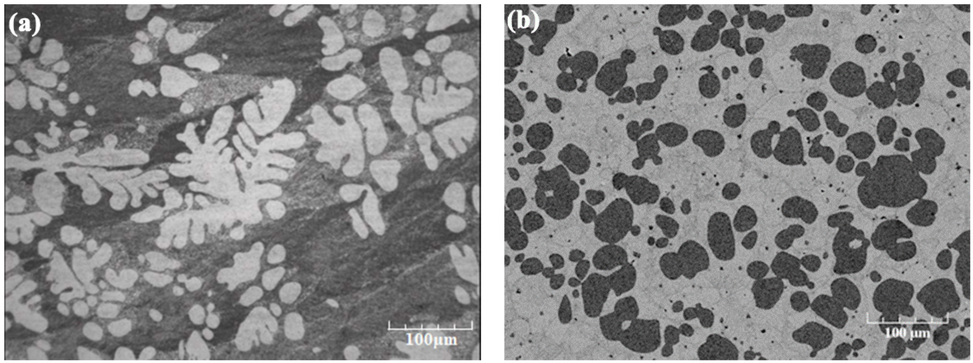
Figure 1. Typical microstructure of (a) dendritic morphology formed under conventional solidification, (b) non-dendritic solid particles formed under intensively forced convection for SSM processing.
Crystals 12 01044 g001
Figure 2. Schematic illustration of the stages of new rheocasting (NRC) process. Reprinted with permission from Ref. [23]. Copyright 2001 John Wiley and Sons.
Crystals 12 01044 g002
Figure 3. Schematic layout of different semi-solid process. Reprinted with permission from Ref. [26]. Copyright 2003 Springer Nature Customer Service Centre GmbH, Springer Nature.
Crystals 12 01044 g003
Figure 4. Schematic of rheomoulding process. Reprinted from [29] with permission of Advanced Manufacturing Research Institute, National Institute of Advanced Industrial Science and Technology (AIST).
Crystals 12 01044 g004
Figure 5. Schematic showing the thixomoulding process according to reference [32,33]. Reprinted under the Creative Commons Attribution License (CC-BY) 4.0.
Crystals 12 01044 g005
Figure 6. Schematic of the rheomixing process to achieve fine and homogeneous microstructure in immiscible alloys, (a) homogeneous liquid (above the Tc); (b) creation of the L′′ droplets in L′; (c) rheomixing: formation of a primary α-Al solid phase (S) in L′ through a monotectic reaction. Reprinted with permission from Ref. [99]. Copyright 2009 Springer Nature Customer Service Centre GmbH, Springer Nature.
Crystals 12 01044 g006
Figure 7. Schematic diagram of different flow modes system (a) horizontal agitation; (b) vertical agitation; (c) helical agitation [108]. Reprinted under the Creative Commons Attribution License (CC-BY) 4.0.
Crystals 12 01044 g007
Figure 8. Schematic of the slope cooling technique for SSM processing [121]. Reprinted under the Creative Commons Attribution License (CC-BY) 4.0.
Crystals 12 01044 g008
Figure 9. Schematic illustration of the continuous rheoconversion process (CRP) [123].
Crystals 12 01044 g009
Figure 10. Illustration of the steps of the Semi-solid rheocasting, in which molten alloy is held above the liquidus (Step 1), then rapidly cooled and agitated for a controlled duration to a temperature below the liquidus (Step 2) before agitation and cooling ceases (Step 3) [125].
Crystals 12 01044 g010
Figure 11. Schematic diagram of the steps of the GISS method [130,132]. Reprinted with permission from Ref. [130]. Copyright 2010 Elsevier.
Crystals 12 01044 g011
Figure 12. Schematic diagram of the SEED process. Reprinted with permission from Ref. [133]. Copyright 2006 SAE International.
Crystals 12 01044 g012
Figure 13. Schematic diagrams of the ultrasonic vibration device. Reprinted with permission from Ref. [142]. Copyright 2011 Elsevier.
Crystals 12 01044 g013
Figure 14. Schematic diagram of SCR process. Reprinted from [149] with permission from Elsevier.
Crystals 12 01044 g014
Figure 15. Comparison of (a) SIMA and (b) RAP [151,153]. T denotes temperature.
Crystals 12 01044 g015
Figure 16. Schematic diagram of RSF process, consisting of pouring liquid metal into an insulated container (Step 1), then submerging a solid metal alloy, usually in the form of a bar of the same composition, into the melt (Step 2), and obtaining semi-solid slurry after the stirring operation (Step 3) [165].
Crystals 12 01044 g016
Figure 17. Schematic of dendrite arm fragmentation mechanism, (a) un-deformed dendrite; (b) after bending; (c) formation of high angle grain boundary by recrystallization; (d) fragmentation through wetting of grain boundary by liquid metal. L stands for liquid phase, and S stands for solid dendritic grain. Reprinted with permission from Ref. [173]. Copyright 1984 Elsevier.
Crystals 12 01044 g017
Figure 18. Schematic diagram of dendrite multiplication [108]. Reprinted under the Creative Commons Attribution License (CC-BY) 4.0.
Crystals 12 01044 g018
Figure 19. Schematic illustration of morphological transition from dendritic to spherical via rosette with increase in shear rate and intensity of turbulence. Reprinted with permission from Ref. [183]. Copyright 2002 Springer Nature Customer Service Centre GmbH, Springer Nature.
Crystals 12 01044 g019
Figure 20. Morphological evolution of spheroidal α-Mg particles in AZ91D alloy during isothermal shearing at low shear rate at 589 °C for different times, (a) 0 min; (b) 70 min; (c) 110 min. Reprinted with permission from Ref. [190]. Copyright 2006 Elsevier.
Crystals 12 01044 g020
Figure 21. The shear stress and velocity distribution and the schematic of the microstructural development during melt flow over the inclined surface. Reprinted with permission from Ref. [210]. Copyright 2012 Springer Nature Customer Service Centre GmbH, Springer Nature.
Crystals 12 01044 g021
Figure 22. Backscattered SEM micrographs showing water-quenched microstructures of Zn-5 wt% Al alloy at initial stage of eutectic solidification, the alloy was continuously sheared at 4082 s−1, cooled at 1 °C/min from 385 °C to 380.6 °C, and times after reaching 380.6 °C for 120 s (white: Zn phase, black: Al phase) [218]. Reprinted under the Creative Commons Attribution License (CC-BY) 4.0.
Crystals 12 01044 g022
Figure 23. Diagram showing the effect of forced convection during eutectic solidification on the morphology of eutectic phases in binary alloys: (a) without forced convection, (b) low intensity of forced convection, (c) moderate intensity of forced convection, and (d) high intensity of forced convection [218]. Reprinted under the Creative Commons Attribution License (CC-BY) 4.0.
Crystals 12 01044 g023
Table 1. Types of materials joined by semi-solid metal joining [13,40].
Substrate ASubstrate BInterlayer CombinationRef.
CuZn40Al2Tool steel [47]
Stainless steelAluminium alloy [48]
Aluminium alloy, stainless steel or cast ironParticles, balls, short fibres of materials including ceramic, aluminium alloys, copper alloys, or stainless steels [40,42,49,50]
Stainless steelM2 tool steel [51]
X210CrW12, 100Cr6, X5CrNil18-109SMn28, CuCo2Be, CuSn12, and GBZ12 [37,52]
Sn-15 wt%PbSn-15 wt%PbSn-5wt%Pb[39]
Pb-15 wt%SnPb-15 wt%Sn [53]
Zinc AG40A die cast alloyZinc AG40A die cast alloy [54]
A356A356 [55]
SiCP/A356 composites2024 aluminium alloyZn-Al[56]
SiCP/A356 compositesSiCP/A356 compositesZn-Al[57]
AZ91 alloyAZ91 alloyMg-25wt%Zn[58]
A356 aluminium alloyA356 aluminium alloy [59]
D2 tool steelD2 tool steel [46,60]
D2 tool steel304 stainless steel [61]
D2 tool steelM2 tool steel [62]
Publisher’s Note: MDPI stays neutral with regard to jurisdictional claims in published maps and institutional affiliations.