Article

Microstructure and Mechanical Properties of Laser Narrow-Gap Multi-Pass Weld 20 mm-Thick Ti-6Al-4V Alloy with Different Filling Layers

State Key Laboratory of Advanced Welding and Joining, Harbin Institute of Technology, 92 West Dazhi Street, Harbin 150001, China
*
Authors to whom correspondence should be addressed.
Crystals 2022, 12(7), 977; https://doi.org/10.3390/cryst12070977
Submission received: 16 June 2022 / Revised: 1 July 2022 / Accepted: 5 July 2022 / Published: 13 July 2022
(This article belongs to the Special Issue Laser Melting of Metals and Metal Matrix Composites)

Abstract

:
In the narrow-gap multi-layer welding of thick Ti-6Al-4V titanium alloy sheets, reducing the number of filling layers can effectively improve the welding efficiency and reduce the possibility of interlayer defects. In order to explore the changes in the microstructure and properties of the weld after reducing the number of filling layers, Ti-6Al-4V titanium alloy sheets with a thickness of 20 mm were successfully welded using the oscillating laser beam mode by laser narrow-gap multi-pass wire filler welding in eight, six, four, and three layers, and all of the formations were good. To reduce the number of filling layers and increase the welding line energy from 0.4 kJ/mm to 1.2 kJ/mm, the melting depth and width of the single layer were changed from 4.3 mm to 10.6 mm, and 5.7 mm to 10.3 mm. The average grain size of the needle-shaped martensite increased from 1.83 μm to 2.38 μm, while the tensile strength of the filled weld area decreased from 1301.8 MPa to 1169.8 MPa, which was higher than that of the base metal of 902.1 MPa. Since there are more columnar crystals in the center of the weld at low heat input, the impact energy was 20.53 J (60.6% of the base metal) at room temperature and 15.76 J (65.9% of the base metal) at −50 °C. Considering the weld formation, microstructure and mechanical property, welding four layers of fillers obtained with moderate line energy (0.8 kJ/mm) was more suitable.

1. Introduction

Ti-6Al-4V titanium alloy has been widely used in marine, deep submersibles, and aerospace equipment fields in its thick-plate form due to its excellent performance, and its connection often needs to be realized by the welding method [1,2]. Considering efficiency and quality, single-penetration welding is an ideal solution for thick-plate materials, but high-power laser welding often has defects such as sag, edge bite, and back hump [3]. Meanwhile, vacuum laser welding and electron beam welding have equipment limitations with regard to the size of the welding materials [4]. In TIG and MIG arc welding, the groove opening on the material is often larger, and more metal needs to be filled. Defects such as low welding efficiency, a wide range of heat-affected zones, and coarse weld microstructure exist [5,6,7]. In addition, the diffusion welding method and the friction welding method can also realize the connection of a thick-plate titanium alloy [8,9,10], but the size of the material is greatly limited.
A laser narrow-gap multi-pass (NGMP) weld with filler wire gives full play to the advantages of high laser energy density and a small heat source action area and can realize the melting of filler wire with small input power in a narrow-groove welded joint [11,12,13]. These features facilitate low distortion, low cost, and high-quality thick-plate titanium alloy welding. The weld usually has two parts in this welding method: the filling layer and the root layer. Due to the characteristics of the narrow gap in the filling layer, the related research mostly adopted the multi-layer single-channel filling method. However, there is no clear conclusion on the selection and design of the number of filling layers in the research related to the filling layer.
Feng et al. [14] used a laser narrow-gap multi-pass welding method to weld 30 mm-thick SA508 steel. The groove depth was 27 mm, and eight layers were filled. The average height of the filled layer was 3.375 mm. The results show that the fine distribution of carbides produced by the NGMP process led to a superior combination of strength and toughness than what was achieved within the parent material, validating the feasibility of the laser process applied to the connection of nuclear pressure vessel steel. Sun et al. [15] used the same method to weld 11 mm Inconel 617 without a defect and carried out five passes of filling in a 9 mm-deep groove with an average filling height of 1.8 mm. The welding efficiency increased while the consumption of filler metal decreased greatly with the laser narrow-gap multi-pass welding method. Wu et al. [16] designed a 22 mm-deep groove on a 35 mm-thick steel CLF-1 and carried out 17 filling steps with an average filling height of 1.3 mm. The repeated heating on the upper weld bead did not significantly change the weld near the transition region but increased grain size.
Cui et al. [17] used TA2 welding wire as filler metal to weld a 10 mm-thick TC4 titanium alloy plate with an ultra-narrow-gap laser. The 8.5 mm-deep groove was filled with five filling layers, with an average layer height of 1.7 mm. Since the strength of the filler material was lower than that of the base metal, the maximum tensile strength of the welded joint reached 893 Mpa, which was close to 84.7% of the base metal, and the fracture position was in the center of the weld. Liu et al. [18] filled a 4 mm groove on a 7.5 mm TC4 plate with four filling layers with an average filling height of 1 mm. The results reveal that repeated remelting and heating effects were the main reasons for the coarsening of acicular martensite in the lower layer.
For practical applications, higher efficiency (lower filling layers) was an important requirement, so the effect of heat input and the number of filling layers on the joint should also be carefully considered, especially on the microstructure characteristics and mechanical properties. Fang et al. [19] filled a 10 mm-thick TC4 board with TC3 wire using different heat inputs. The proportion of columnar grains in the weld decreased with the increase in welding heat input.
For the laser narrow-gap filling welding method, there is no clear conclusion on the selection and design of the number of filling layers in the research related to the filling layer. Especially for the TC4 titanium alloy material, few researches have been done on the effect of the number of filling layers on the microstructure and properties. In this paper, 20 mm-thick Ti-6Al-4V titanium alloy was taken as the research object, and the welding joints with different filling layers and heat input were welded by laser NGMP welding with wave laser in the form of narrow-gap groove. The morphological changes and performance differences of the welded joints were comparatively studied, providing reference and guidance for laser NGMP welding of thick-plate titanium alloy and other materials.

2. Materials and Experimental Methods

2.1. Materials

The base material was Ti-6Al-4V titanium alloy, and the size of each plate was 200 × 100 × 20 mm. Its chemical composition and main properties are listed in Table 1, while its microstructure is shown in Figure 1. The filler wire of 1.2 mm in diameter had the same base metal composition.

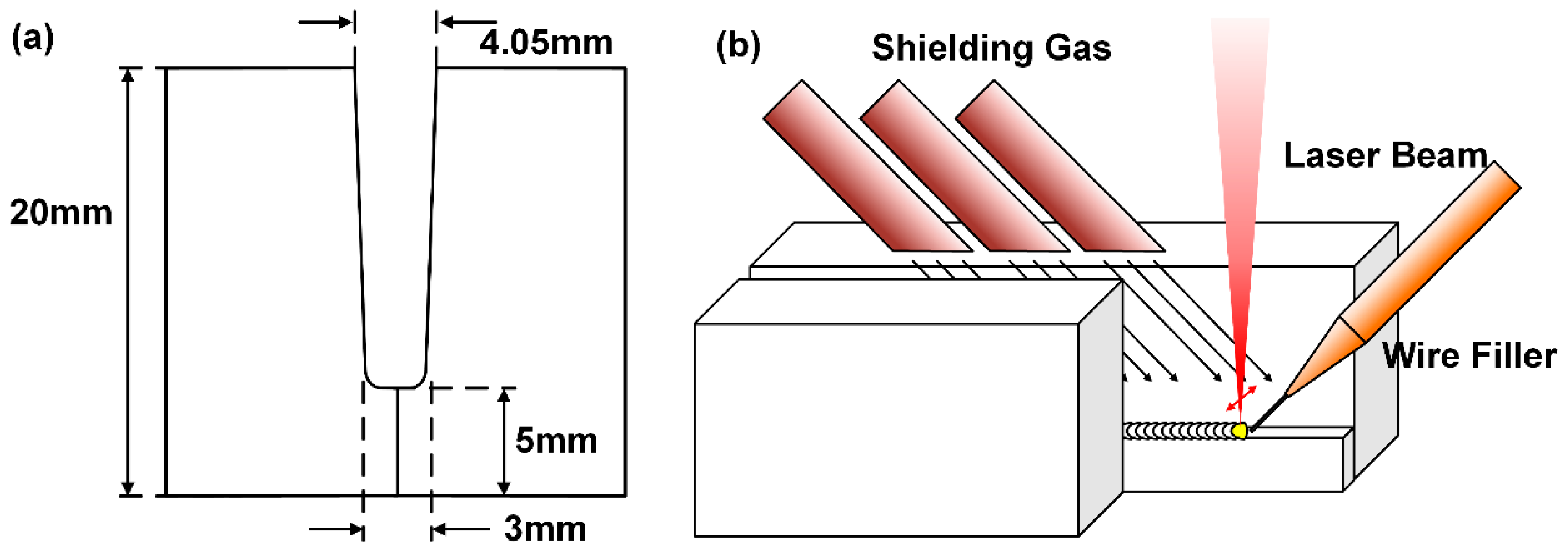
2.2. Experimental Method

The laser welding experiment was carried out using an IPG YLS4000 multi-mode fiber laser with a maximum output power of 4 kW. We adopted a vibrator-type laser head from the HIGHYAG company to realize the vibration of the laser beam track. Its parameters were as follows: focal length f = 250 mm, the fiber core diameter D = 400 μm, and the focal spot diameter D = 0.67 mm.
The size of the groove design and the schematic of laser NGMP welding with the filler wire is depicted in Figure 2. A U-shaped 15 mm-deep welding groove with a 3 mm width and a 4 mm root face was designed for the laser welding.
A gantry-type movement mechanism provided the manipulation of the welding head with welding in the horizontal (G1) position. The weld sample was clamped to the welding platform during the welding process. The filler wire was inclined at 45° to the laser beam, and the wire extension was 10 mm. The argon (99.999%) was used as a shielding gas to prevent oxidation during welding by three 20 mm-diameter copper pipes, which blew argon from the top of the groove inward. The results show that the protection effect was good, and the weld surface was bright silver after welding. The specific parameters are discussed in the Section 3.

2.3. Microstructure Observation

Electro-discharge machining was used to cut the joints into specimens after the welding. The specimens were ground and polished, followed by the metallographic corrosion in Keller reagent (HF:HNO3:H2O = 3:7:90) for the macro- and microscopic examinations via an inverted metallographic microscope. The EBSD samples were cleaned via electropolishing in a solution of 5% perchlorate ethanol and 90% alcohol at approximately 0 °C and 20 V for 60 s. An FEI Quanta 650 F scanning electron microscope (SEM) equipped with the HKL Channel 5 software was used for the EBSD data acquisition and analysis.

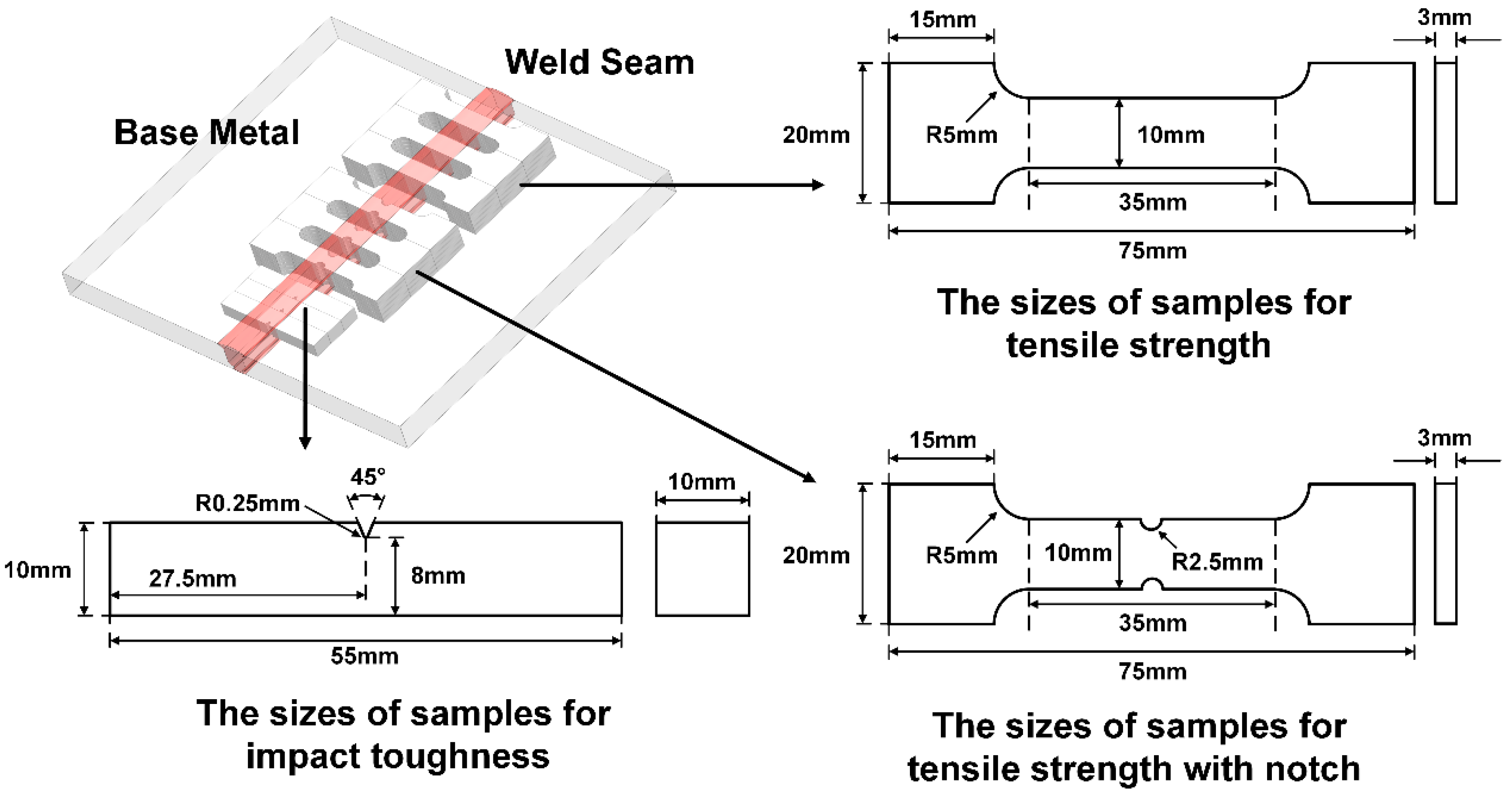
2.4. Test of the Mechanical Properties

The specific sampling location and size of mechanical test parts are shown in Figure 3.
The Vickers microhardness measurements were conducted on a transverse cross-section with a load of 200 g and a dwell time of 15 s. The tensile samples with 3 mm thickness were cut from five locations varying in thickness and prepared in compliance with GB/T 228. Tensile tests were conducted at room temperature with a constant cross-head speed of 1 mm/min. To significantly compare the difference in microstructure and properties of the weld zone, the tensile test piece with a notch in the weld zone was specially designed.
The impact toughness samples were cut from the middle part of the joint with a size of 55 × 10 × 10 mm. The notch was a 45° 2 mm-deep V-notch, and the bottom fillet radius was 0.25 mm.
Failed specimens were examined using a Zeiss AURIGA scanning electron microscope to identify the fracture patterns.

3. Results and Discussion

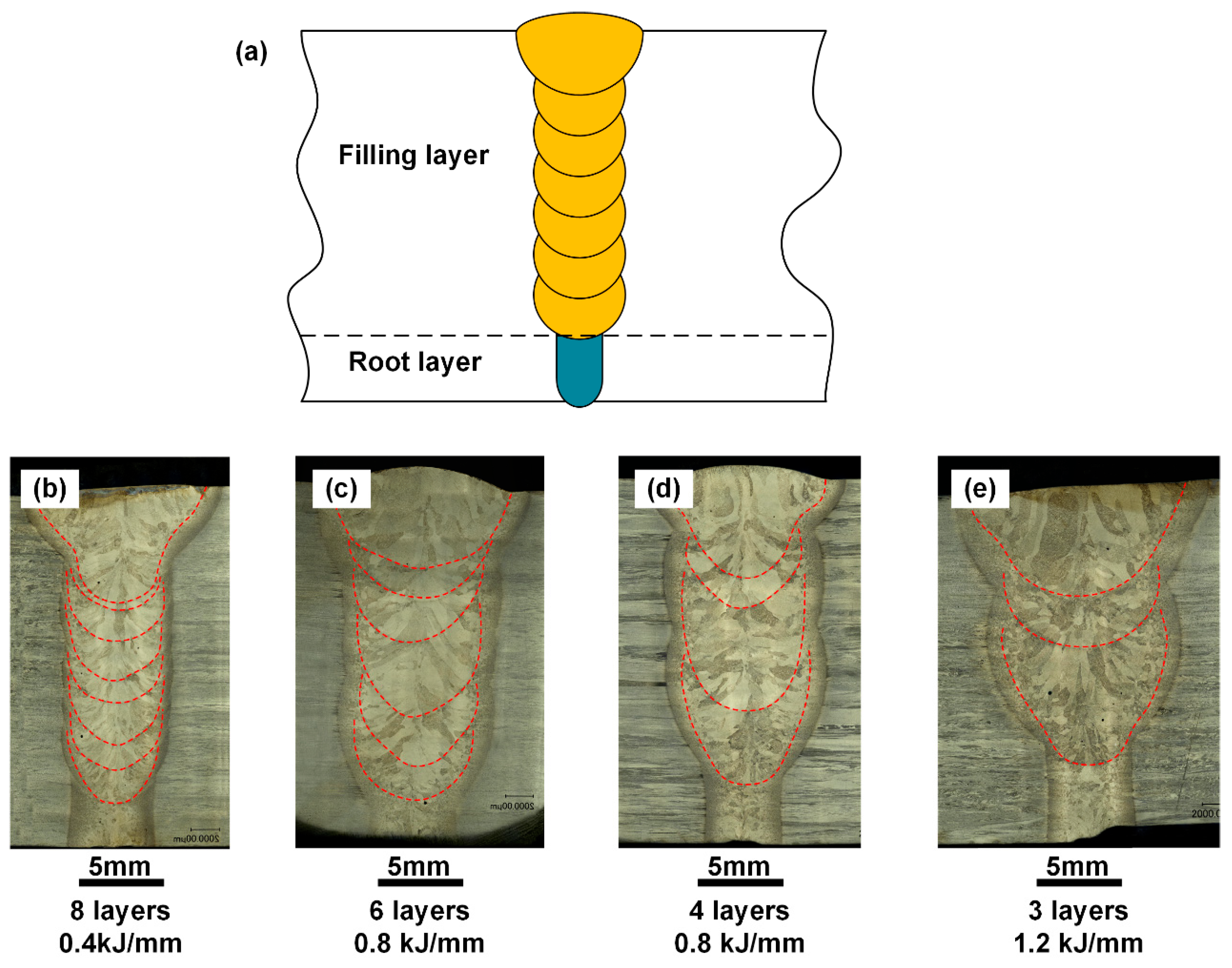
3.1. Paraments and Weld Formation

According to the characteristics of the groove, it could be divided into two areas: the filling layer and the root layer. The root layer generally refers to the blunt-edge area welded by laser self-fusion at the bottom of the original groove design, with a range of about 5 mm. The filling layer refers to the area that fills the designed groove, which generally accounts for the largest proportion of the joint and is also the main research focus of this paper. In addition, the area that is finally filled in the filling layer is also called the cover layer with the consideration of the quality of the weld surface to prevent bad forming such as edge biting; its parameters are often different from those used in the filling layer. Therefore, the area studied in this paper was in the center of the weld.
In this research, laser pulse welding was selected as the root layer welding process, and the main parameters were: laser power 4000 W, welding speed 0.5 m/min, defocusing quantity −2 mm, pulse frequency 60 Hz, and duty cycle 0.8.
Among the parameters used in the filling layer area, there were three main adjustable parameters: laser power, welding speed, and wire feeding speed [20]. As shown in Table 2, the laser power was fixed at 4000 W in the study, and the amount of filling metal was controlled by adjusting the ratio of welding speed and wire feeding speed to obtain filling welds with different filling heights. To improve the stability of the welding process, the swing laser beam mode was adopted for the filling welding, the swing trajectory had a vertical swing, the swing amplitude was 2 mm, and the swing frequency was 60 Hz.
The cross-section characteristics are shown in Figure 4. The welding seam was composed of a root layer and a filling layer. This study compared the filling layer’s differences under different process conditions. Therefore, welds with different filling layers were obtained by using different process conditions. When the weld was obtained with low line energy (0.4 kJ/mm), the filling layer consisted of eight filling welds with a very low filling height (average 1.9 mm), as shown in Figure 4b. Similarly, due to the limited heat input, the penetration depth and width of the single-filling weld were lower, 4.3 mm and 5.7 mm, respectively.
As shown in Figure 4c, with higher line energy (0.8 kJ/mm), the number of ling welds was reduced on average to six layers, and the average filling height of each layer was 2.5 mm. Each layer’s penetration depth and width increased to 6.9 mm and 7.1 mm. It can be seen that the energy used to melt the filler wire was not much at this time. Under this line energy condition, the filler wire can be further increased, the number of filling layers can be reduced to four layers, and the average filling height was increased to 3.75 mm, as shown in Figure 4d.
By further increasing the line energy to 1.2 kJ/mm, a three-layer weld can be obtained. At this time, the single-layer penetration depth and width had reached 10.6 mm and 10.3 mm. It could also be seen that a large amount of energy was distributed on the molten substrate, and less energy is used to melt the filler material. Moreover, the larger melting width also easily led to the transitional ablation of the sidewall, which would affect the welding quality.

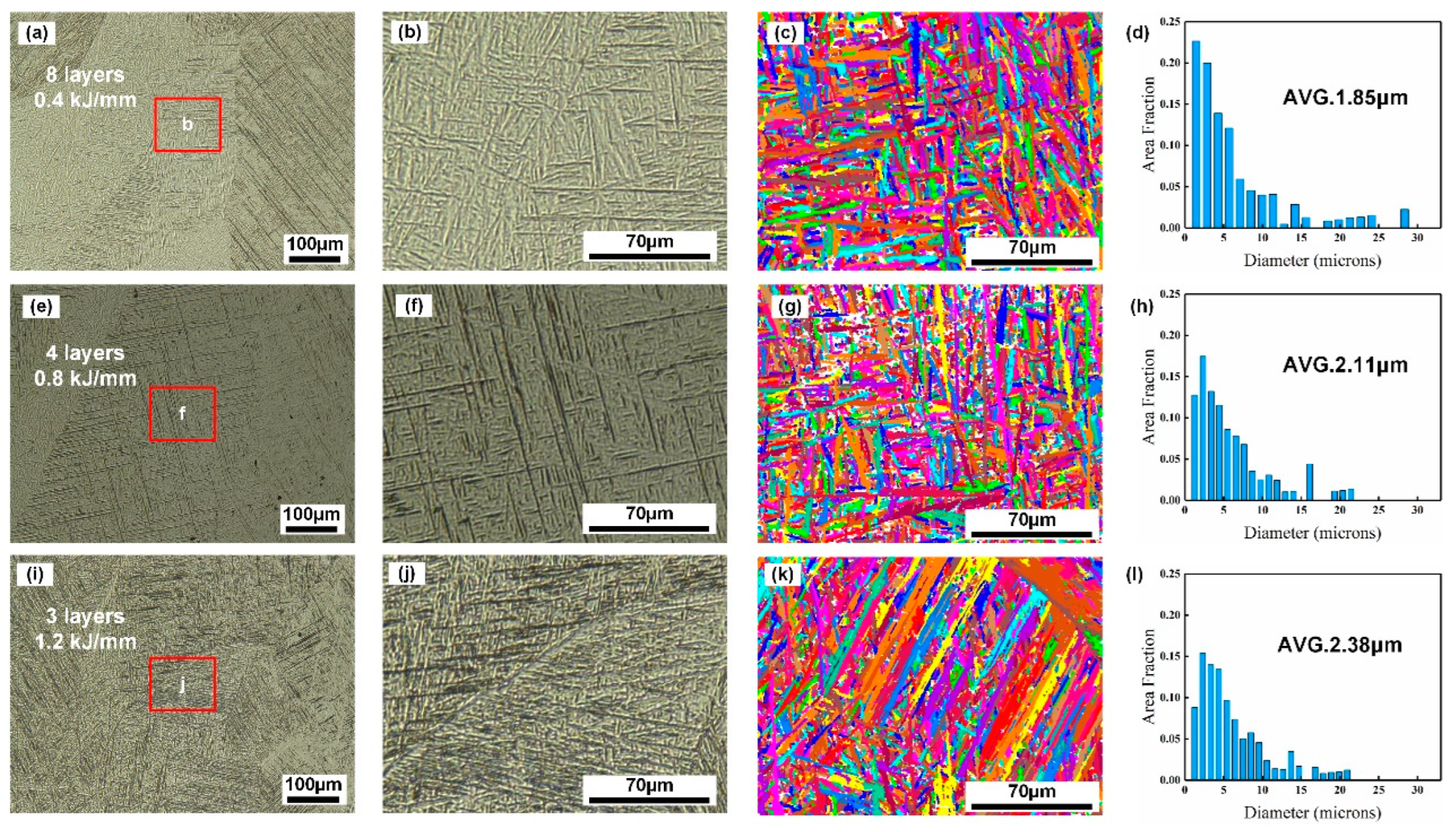
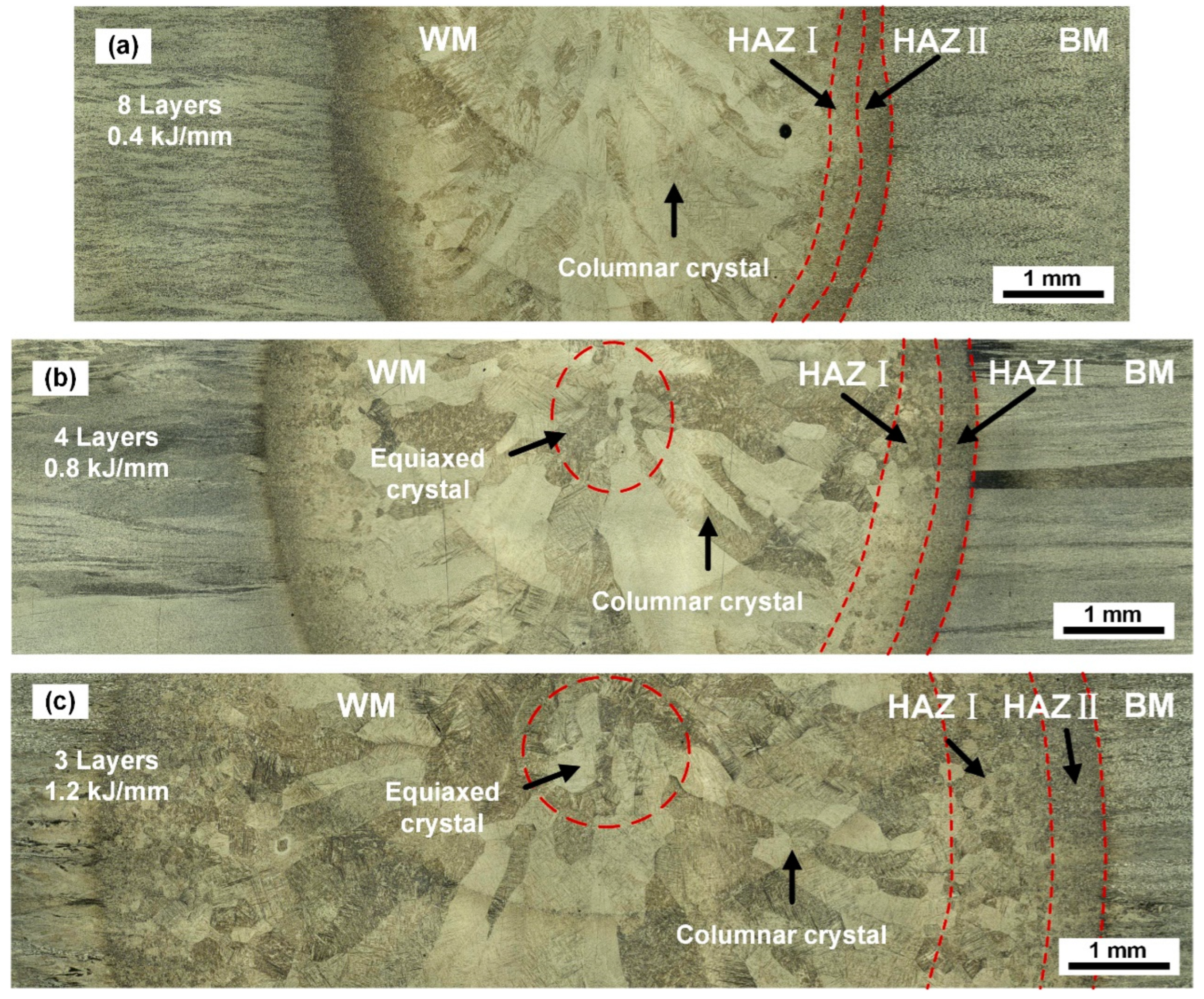
3.2. Microstructure of Different Specimens

The microstructure characteristics of the filling area of the four weld samples are shown in Figure 5. The weld area was mainly composed of columnar crystals growing from the edge to the center with the needle-shaped martensite distributed in the basket inside. With the increase in heat input, the size of columnar crystals also increased.
Under lower heat input (0.4 kJ/mm), the average columnar crystal width of the eight-layer sample was about 434.8 μm. The overall width of the heat-affected zone was about 650 μm, of which HAZ I (fine-grained region) and HAZ II (coarse-grained zone) each accounted for half, about 320 μm. HAZ I (fine-grained region) had a short residence time above the phase transition temperature, and there was not enough time for the grains to grow. However, the peak temperature in HAZ II (coarse-grained zone) was close to the melting point, the residence time at a high-temperature was longer, the grains grew further, and the microstructure was partially transformed into the needle-shaped martensite α’ phase.
After increasing the heat input, the microstructure in HAZ I (fine-grained area) did not change much; it was still an α phase + β phase, and the overall width increased slightly, reaching about 400 μm at 0.8 kJ/mm, and 1.2 J/mm to around 600 μm. The change of HAZ II (coarse-grained zone) was more obvious, and the range increased to about 600 μm at 0.8 kJ/mm, the internal grains grew significantly, and large-volume equiaxed crystals appeared, and there were more α phases distributed inside. Furthermore, the heat input was increased to 1.2 kJ/mm, and the HAZ II (coarse-grained zone) range was about 1000 μm. Due to the higher high-temperature residence time and residence temperature, the grains in the region were sufficiently grown and transformed into the β phase, so at that time, the predominant organization in the region was the α’ phase that transformed upon cooling.
The microstructure in the weld zone was similar, being mainly composed of coarse columnar grains. This was due to the rapid cooling of the weld zone during the solidification stage, and the higher temperature echelon that made the β phase grow rapidly after nucleation and grow toward the center of the weld along the direction of the fastest cooling rate. Under higher line energy conditions (0.8 kJ/mm and 1.2 kJ/mm), the maximum temperature of the molten pool increased, the range of the high-temperature zone in the center of the weld increased, and the high-temperature residence time also increased. The above conditions decreased the temperature gradient, the growth rate of columnar crystals decreased, and in the final solidification region, more grains nucleated and formed more equiaxed crystals. Correspondingly, the average columnar crystal widths were also increased to about 571.4 μm and 811.5 μm, respectively. In the further cooling process, due to the fast cooling rate, the original β-phase columnar crystals could only be sheared and transformed into the needle-shaped martensite α’ phase, which could be observed as it was also the microstructure of the final weld.
To further analyze the characteristic difference, the EBSD analysis was carried out in Figure 6. The results show that with the increase in heat input, the grain size greatly changed. Under the condition of 0.4 kJ/mm, the average grain size of the needle-shape martensite α’ phase in the central area of the weld was about 1.85 μm. As the line energy increased to 0.8 kJ/mm and 1.2 kJ/mm, the average grain size increased to 2.11 μm and 2.38 μm, respectively.

3.3. The Weld Joint Mechanical Properties

3.3.1. Microhardness

Figure 7 shows the microhardness result for depth direction. Under different filling layers and heat input conditions, all specimens had similar characteristics. The root layer had a higher hardness, about 370 HV, due to different process parameters.
The hardness of the filling layer with a large range decreased from the surface (370 HV) to the bottom (345 HV). It can be considered that due to the layer-by-layer welding process, the welding thermal cycle during the post-weld welding made the solidified region receive heat treatment, so the dislocation density of grains in this region decreased, and the grains also grew to a certain extent. According to the Hall–Petch formula, at room temperature, the smaller the grain size, the more grain boundaries contained in the unit volume, and the better the strengthening effect [21,22], so the bottom of the filling layer exhibited lower hardness.

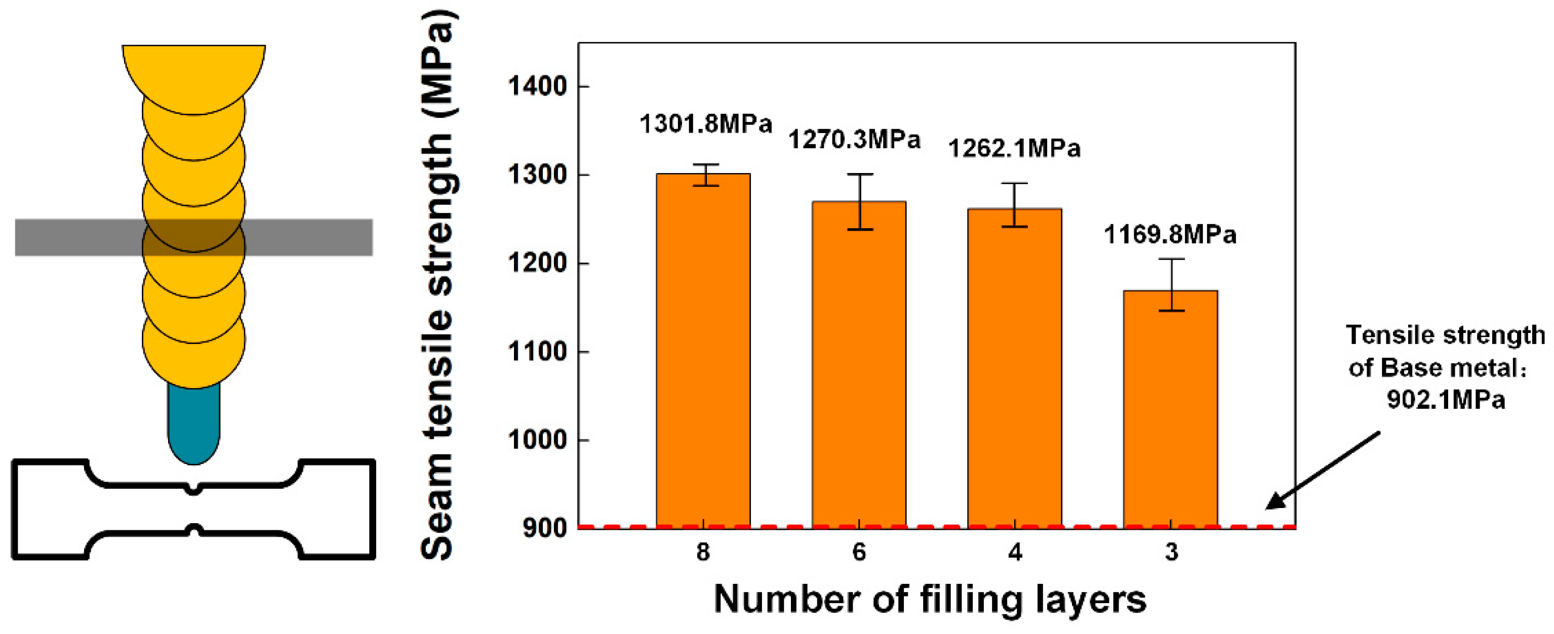
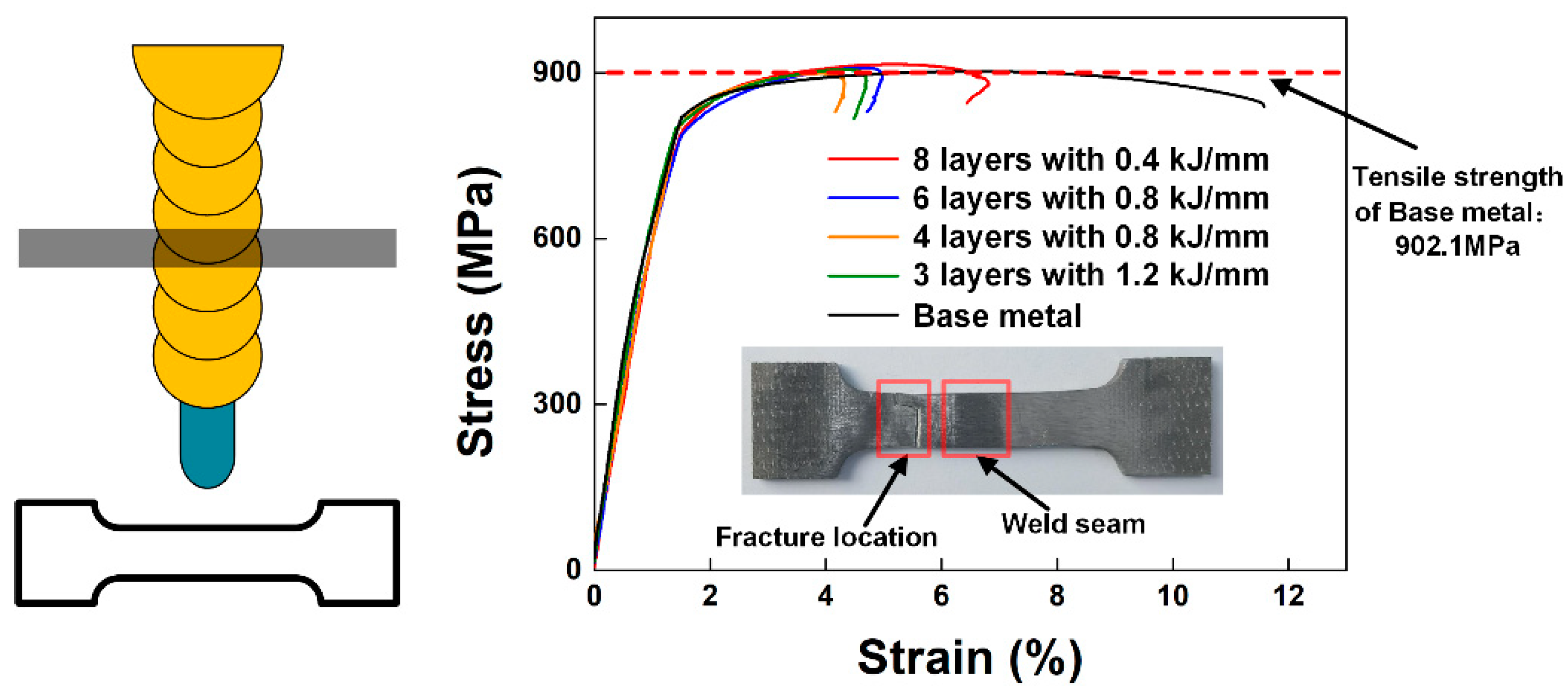
3.3.2. Tensile Strength

The four welds were tested by layered tensile tests, respectively, and the results are shown in Figure 8. All the specimens were fractured at the base metal position, and the tensile strength was in the range of 900–930 Mpa, indicating that the strength of the weld area was higher than that of the base metal. The elongation after fracture was about 4.5%, except for the eight-layer filled weld, for which it was about 7.5%.
To further study the influence of the microstructure change caused by the number of filling layers on the tensile strength of the weld, the tensile strength of each weld position was tested by stratification. The results show that the welding seam strength was higher than the average layer height, as shown in Figure 9.
The results show that the strength of an eight-layer filled weld with a 0.4 kJ/mm line energy reached 1301.8 MPa, while it was about 1169.8 MPa for the three-layer filled weld with a 1.2 kJ/mm line energy.
Combined with the analysis of the microstructure characteristics, it can be considered that when the number of filling layers was large with a low line energy, the lower peak temperature and high-temperature residence time led to a larger cooling rate, so the final microstructure of the weld area was finer. In the tensile test, the dense grain boundary had a strong ability to resist deformation [21,22], thus exhibiting higher strength. With the increase in line energy, the size of solidified grain in the weld zone became larger and the grain boundary density decreased, so it became more easily deformed under tensile load and exhibited lower tensile strength. These phenomena are consistent with the results of the tissue analysis.

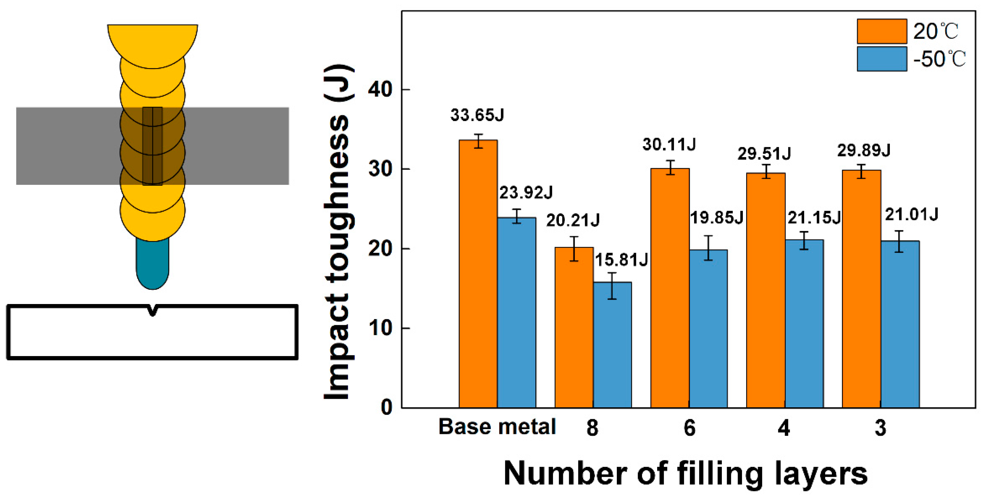
3.3.3. Impact Toughness

To further measure the reliability of the joint and the difference between different structures, impact toughness tests were carried out on the weld filling area of the four specimens at room temperature and low temperature, and the results are shown in Figure 10. Under these conditions, the impact toughness of the base metal was 33.85 J at room temperature and 23.92 J at −50 °C. The impact toughness of the weld specimens at both room temperature and low temperature decreased to a certain extent compared with the base metal. Interestingly, the weld with the highest tensile strength and the smallest grain size (eight-layer filled weld, line energy 0.4 kJ/mm) decreased the most, and the impact energy at room temperature was 20.53 J (60.6% of the base metal). The impact energy was 15.76 J (65.9% of base metal) at −50 °C. The impact toughness strength of other welds was about 80% of that of the base metal, which is close to the results of other studies [23,24].
The fracture morphology is shown in Figure 11, and no obvious shear lip was observed on the fracture. Compared with the other three specimens, the specimen with low linear energy and a small single-layer filling height (eight-layer filled weld, line energy 0.4 kJ/mm) had a smoother macroscopic fracture shape, with a larger number of smoothly stepped cleavage surfaces and small dimples.
Observing the fracture paths of different specimens shown in Figure 12, it can be seen that the fracture path of the eight-layer filled weld extended straight along the center of the weld, and there were symmetrically distributed columnar crystals on both sides of the path. For specimens with a higher single-layer filling height, the fracture path was deflected to a certain extent and passed through multiple grains.
It is speculated that there were continuous columnar crystals in the center of the eight-layer filled weld, and the densification made it easier for the crack to expand continuously in this area. Therefore, in the impact toughness test with the gap open, the absorption energy was low. The equiaxed grain zone in the center of the weld of other specimens had a certain hindering effect on the crack propagation, showing a higher performance.

4. Conclusions

A Ti-6Al-4V titanium alloy plate with a thickness of 20 mm was successfully welded by a laser narrow-gap multi-pass weld with filler wire with a swing laser beam mode.
(1) Welds with filling layers of eight, six, four, and three layers were obtained through different optimized process conditions. Correspondingly, the line energy increased from 0.4 kJ/mm to 1.2 kJ/mm, the single-layer melting depth changed from 4.3 mm to 10.6 mm, and the melting width changed from 5.7 mm to 10.3 mm. All the welds were free of pores, cracks, and the incomplete fusion phenomenon.
(2) The microstructure of a weld is mainly composed of β-columnar crystals growing from the edge to the center and the needle-shaped martensite α’ phase densely arranged inside in basketweave. Its morphology is a cellular grain near the fusion line and coarse columnar grain growing toward the center. Due to the increase in heat input, the needle-shaped martensite average grain size (2.38 μm) of the weld with high heat input (1.2 kJ/mm) was 28.6% higher than that of the weld with low heat input (0.4 kJ/mm) (1.83 μm). The tensile strength of the joint was higher than that of the base metal (902.1 MPa). The weld with low heat input (0.4 kJ/mm) had a higher strength due to the finer grain structure and dense grain boundaries, at 1301.8MPa, while the weld with increased heat input (1.2 kJ/mm) had a strength of 1169.8MPa.
(3) The impact toughness results show that the impact toughness of the weld zone was lower than that of the base metal at room temperature and low temperature (20 °C: 33.85 J, −50 °C: 23.92 J). However, due to the more columnar crystals in the center of the weld, the impact absorption energy corresponding to the weld with low heat input (0.4 kJ/mm) was lower: the impact energy was 20.53 J (60.6% of the base metal) at room temperature and 15.76 J (65.9% of the base metal) at −50 °C. The other three groups of welds could reach 80–90% of the base metal.
(4) Under the condition of lower line energy (0.4 kJ/mm), more filling layers (eight layers) were required to complete the welding with a small heat-affected zone(HAZ), but more columnar crystals in the weld area weakened the impact toughness of the joint; when using a higher line energy (1.2 kJ/mm), although three layers of filling layers could be used to complete the welding, too much energy was distributed in the melting base metal area. On the one hand, the energy utilization rate was low, and on the other hand, the thermal area tissue coarsening was more serious. The welding of four layers of filling layers obtained with moderate line energy (0.8 kJ/mm) was more suitable.

Author Contributions

S.M.: Conceptualization, Methodology, Visualization, Writing—Original Draft, Data Curation. L.L.: Conceptualization, Funding acquisition, Supervision, Project administration. W.T.: Methodology, Visualization, Supervision. J.G.: Conceptualization, Methodology. C.S.: Methodology, Data Curation. All authors have read and agreed to the published version of the manuscript.

Funding

This research was funded by the National Key Research and Development Program of China under Grant No. 2016YFB1102100 and Natural Science Foundation of Heilongjiang Province under Grant No. GX17A001.

Data Availability Statement

Not applicable.

Conflicts of Interest

The authors declare no conflict of interest.

References

  1. Lu, J.Z.; Lu, H.; Xu, X.; Yao, J.; Cai, J.; Luo, K. High-performance integrated additive manufacturing with laser shock peening-induced microstructural evolution and improvement in mechanical properties of Ti6Al4V alloy components. Int. J. Mach. Tools Manuf. 2020, 148, 14. [Google Scholar] [CrossRef]
  2. Calamaz, M.; Coupard, D.; Girot, F. A new material model for 2D numerical simulation of serrated chip formation when machining titanium alloy Ti-6Al-4V. Int. J. Mach. Tools Manuf. 2008, 48, 275–288. [Google Scholar] [CrossRef] [Green Version]
  3. Kawahito, Y.; Wang, H.; Katayama, S.; Sumimori, D. Ultra high power (100 kW) fiber laser welding of steel. Opt. Lett. 2018, 43, 4667–4670. [Google Scholar] [CrossRef] [PubMed]
  4. Jian, L.A.; Long, J.; Zhang, L.J.; Ning, J.; Ma, Z.X.; Zang, S.L. Zoning study on the fatigue crack propagation behaviors of a double-sided electron beam welded joint of TC4 titanium alloy with the thickness of 140 mm. Int. J. Fatigue 2021, 146, 106145. [Google Scholar]
  5. Bayley, C.J.; Mantei, A. Influence of Weld Heat Input on the Fracture and Metallurgy of HSLA-65. Can. Metall. Q. 2009, 48, 311–316. [Google Scholar] [CrossRef]
  6. Viano, D.M.; Ahmed, N.U.; Schumann, G.O. Influence of heat input and travel speed on microstructure and mechanical properties of double tandem submerged arc high strength low alloy steel weldments. Sci. Technol. Weld. Join. 2000, 5, 26–34. [Google Scholar] [CrossRef]
  7. Zhang, C.G.; Lu, P.; Hu, X.; Song, X. Effect of buffer layer and notch location on fatigue behavior in welded high-strength low-alloy. J. Mater. Process.Technol. 2012, 212, 2091–2101. [Google Scholar] [CrossRef]
  8. Guo, Y.; Chiu, Y.; Attallah, M.M.; Li, H.; Bray, S.; Bowen, P. Characterization of Dissimilar Linear Friction Welds of α-β Titanium Alloys. J. Mater. Eng. Perform. 2012, 21, 770–776. [Google Scholar] [CrossRef]
  9. Prikhodko, S.V.; Savvakin, D.G.; Markovsky, P.E.; Stasuk, O.O.; Penney, J.; Shirzadi, A.A.; Davies, P.D.; Davies, H.M. Diffusion bonding of TiC or TiB reinforced Ti–6Al–4V matrix composites to conventional Ti–6Al–4V alloy. Sci. Technol. Weld. Join. 2020, 25, 518–524. [Google Scholar] [CrossRef]
  10. Ma, T.J.; Chen, X.; Li, W.Y. Effect of Process Parameters on Welding Variables during Linear Friction Welding of Ti-6Al-4V Alloy. Adv. Mater. Res. 2011, 314, 979–983. [Google Scholar] [CrossRef]
  11. Dittrich, D.; Schedewy, R.; Brenner, B.; Standfuß, J. Laser-multi-pass-narrow-gap-welding of hot crack sensitive thick aluminum plates. In Proceedings of the 7th International WLT Conference on Lasers in Manufacturing (LiM), Munich, Germany, 13–16 May 2013; Elsevier: Amsterdam, The Netherlands, 2013. [Google Scholar]
  12. Elmesalamy, A.; Francis, J.A.; Li, L. A comparison of residual stresses in multi pass narrow gap laser welds and gas-tungsten arc welds in AISI 316L stainless steel. Int. J. Press. Vessel. Pip. 2014, 113, 49–59. [Google Scholar] [CrossRef]
  13. Zhang, X.D.; Ashida, E.; Tarasawa, S.; Anma, Y.; Okada, M.; Katayama, S.; Mizutani, M. Welding of thick stainless steel plates up to 50 mm with high brightness lasers. J. Laser Appl. 2011, 23, 7. [Google Scholar] [CrossRef]
  14. Feng, J.C.; Rathod, D.W.; Roy, M.J.; Francis, J.A.; Guo, W.; Irvine, N.M.; Vasileiou, A.N.; Sun, Y.L.; Smith, M.C.; Li, L. An evaluation of multipass narrow gap laser welding as a candidate process for the manufacture of nuclear pressure vessels. Int. J. Press. Vessel. Pip. 2017, 157, 43–50. [Google Scholar] [CrossRef] [Green Version]
  15. Sun, J.H.; Ren, W.; Nie, P.; Huang, J.; Zhang, K.; Li, Z. Study on the weldability, microstructure and mechanical properties of thick Inconel 617 plate using narrow gap laser welding method. Mater. Des. 2019, 175, 13. [Google Scholar] [CrossRef]
  16. Wu, S.K.; Zhang, J.; Yang, J.; Lu, J.; Liao, H.; Wang, X. Investigation on microstructure and properties of narrow-gap laser welding on reduced activation ferritic/martensitic steel CLF-1 with a thickness of 35 mm. J. Nucl. Mater. 2018, 503, 66–74. [Google Scholar] [CrossRef]
  17. Cui, B.; Zhang, H.; Zhao, C.; Shao, T. Microstructure and Mechanical Properties of TC4 Titanium Alloy Joint by Ultra-narrow Gap Laser Welding. Mater. Rev. 2018. [Google Scholar]
  18. Liu, J.Z.; Zhan, X.; Gao, Z.; Yan, T.; Zhou, Z. Microstructure and stress distribution of TC4 titanium alloy joint using laser-multi-pass-narrow-gap welding. Int. J. Adv. Manuf. Technol. 2020, 108, 3725–3735. [Google Scholar] [CrossRef]
  19. Dewangan, S. Effect of heat treatment into tensile strength, hardness and microstructural attributes of TIG welded Ti-6Al-4V titanium alloy. Aust. J. Mech. Eng. 2022, 1–10, (ahead-of-print). [Google Scholar] [CrossRef]
  20. Guo, W.; Li, L.; Dong, S.; Crowther, D.; Thompson, A. Comparison of microstructure and mechanical properties of ultra-narrow gap laser and gas-metal-arc welded S960 high strength steel. Opt. Lasers Eng. 2017, 91, 1–15. [Google Scholar] [CrossRef] [Green Version]
  21. Lehto, P.; Remes, H. EBSD characterisation of grain size distribution and grain sub-structures for ferritic steel weld metals. Weld. World 2022, 66, 363–377. [Google Scholar] [CrossRef]
  22. Cui, C.Y.; Cui, X.G.; Ren, X.D.; Liu, T.T.; Hu, J.D.; Wang, Y.M. Microstructure and microhardness of fiber laser butt welded joint of stainless steel plates. Mater. Des. 2013, 49, 761–765. [Google Scholar] [CrossRef]
  23. Zhang, H.; Li, J.; Ma, P.; Xiong, J.; Zhang, F. Study on microstructure and impact toughness of TC4 titanium alloy diffusion bonding joint. Vacuum 2018, 152, 272–277. [Google Scholar] [CrossRef]
  24. Shi, X.; Zeng, W.; Sun, Y.; Han, Y.; Zhao, Y. Study on the Hot Processing Parameters-Impact Toughness Correlation of Ti-6Al-4V Alloy. J. Mater. Eng. Perform. 2016, 25, 1741–1748. [Google Scholar] [CrossRef]
Figure 1. Microstructure of TC4 titanium alloy base metal.
Crystals 12 00977 g001
Figure 2. Size of groove design and the schematic of laser NGMP welding with the filler wire. (a) Size of groove design; (b) welding process.
Crystals 12 00977 g002
Figure 3. The specific sampling location and size of mechanical test parts.
Crystals 12 00977 g003
Figure 4. Weld surface and section forming. (a) Filling weld schematic; (b) 8 layers with 0.4 kJ/mm; (c) 6 layers with 0.8 kJ/mm; (d) 4 layers with 0.8 kJ/mm; (e) 3 layers with 1.2 kJ/mm.
Crystals 12 00977 g004
Figure 5. The microstructure of the weld with different filling layers and line energy. (a) A total of 8 layers with 0.4 kJ/mm; (b) 4 layers with 0.8 kJ/mm; (c) 3 layers with 1.2 kJ/mm.
Crystals 12 00977 g005
Figure 6. Microstructure and EBSD analysis results of different samples. (ad) A total of 8 layers with 0.4 kJ/mm; (eh) 4 layers with 0.8 kJ/mm; (il) 3 layers with 1.2 kJ/mm.
Crystals 12 00977 g006
Figure 7. Microhardness distribution across depth direction of the different weld.
Crystals 12 00977 g007
Figure 8. Tensile test results of the filling layer.
Crystals 12 00977 g008
Figure 9. Tensile test results with a notch in the filling layer.
Crystals 12 00977 g009
Figure 10. Impact toughness results of different welds at 20 °C and −50 °C.
Crystals 12 00977 g010
Figure 11. Fracture morphology of impact test. (a) The macroscopic morphology of 8-layer filled weld; (b) the macroscopic morphology of 4-layer filled weld; (c,d) microscopic morphology of 8-layer filled weld.
Crystals 12 00977 g011
Figure 12. Fracture path of impact test. (a) The fracture path of 8-layer filled weld; (b,c) the microstructure characteristics around the fracture path of 8-layer filled weld; (d) the fracture path of 4-layer filled weld; (e,f) the microstructure characteristics around fracture path of 4-layer filled weld.
Crystals 12 00977 g012
Table 1. Main chemical constituents and mechanical properties of Ti-6Al-4V titanium alloy.
Chemical Constituents (%)Mechanical Properties
AlVFeCNHOTiσb (Mpa)δ (%)
640.30.10.050.0150.2Bal89510
Table 2. Process parameters of multilayer swing laser wire filling welding.
SampleFilling LayersLine EnergyWeld SpeedWire Speed
180.4 kJ/mm0.6 m/min3 m/min
250.8 kJ/mm0.3 m/min3 m/min
340.8 kJ/mm0.3 m/min4.5 m/min
431.2 kJ/mm0.2 m/min4 m/min
Publisher’s Note: MDPI stays neutral with regard to jurisdictional claims in published maps and institutional affiliations.

