Abstract
In this paper, a microstructure-dependent magneto-electro-elastic functionally graded porous (MEEFGP) beam model is proposed using a variational approach. To account for the microstructure effect, the extended modified couple stress theory is incorporated in the new model. In addition, the porosity variation of the two-phase beam model through the thickness direction is also considered. The new developed model is verified in terms of its correctness with a FEM model. Based on the equations of motion and boundary conditions derived by Hamilton’s principle, the static bending and wave propagation behaviors of the new model are analytically determined. The results prove the existence of the microstructure effect and the magneto-electro-elastic multi-field coupling effect. There are significant differences between the new model and the classical model at the microscale. Moreover, the porosity also has an important influence on the mechanical properties of the new model. The results predicted by the new model can provide the theoretical basis for the design of microscale acoustic wave devices and micro-electro-mechanical systems.
1. Introduction
In recent years, as smart materials, magneto-electro-elastic (MEE) materials have attracted more and more attention. The MEE materials can convert electric, magnetic, and elastic energies, which are widely applied in health monitoring, actuation, stability control, and other applications [1,2,3]. Compared with homogeneous materials, functionally graded materials (FGMs) that have continuously varied material properties are found to have better mechanical behaviors [4,5,6,7]. Many micromechanical models of FGM have been developed to predict the effective material properties of FGM. Akbarzadeh et al. [8] studied Voigt, Reuss, Hashin–Shtrikman bounds, LRVE, Tamura, and self-consistent models, and analyzed the influence of different models on the dynamic and static responses of simply supported plates with elastic foundation. Due to the unique energy conversion ability and the superior mechanical performance, magneto-electro-elastic functionally graded materials (MEEFGM) have become the focus of research in recent years. Akbarzadeh et al. [9] established a thermo-magneto-electro-elastic rotating hollow cylinder model made using a functionally graded material, and obtained the analytical solutions for the multiphysical responses of the model. However, because of the differences in solidification of the material constituents during the preparation process, the porosity is a common defect in FGM structures [10,11]. Therefore, it is necessary to consider the porosity in the design and analysis of magneto-electro-elastic functionally graded porous (MEEFGP) materials. Kiran et al. [12] evaluated the effects of the porosity on the static and dynamic responses of functionally graded skew MEE plates. Based on the finite element procedures, Vinyas [13] studied the vibrational behavior of porous functionally graded MEE circular and annular plates. Ebrahimi et al. [14] developed a porous MEEFGM beam and analyzed the buckling behavior of the beam with different thermal loadings and boundary conditions. Vinyas and Dineshkumar [15] studied the large and nonlinear deflection of MEEFGP flat panels. Sh et al. [16] investigated the geometrically nonlinear free vibration rates and transient responses of porous MEEFG plates by applying the first-order shear deformation theory.
As many structures tend toward miniaturization, structures made of MEEFGM at the microscale are also widely applied in micro-electro-mechanical systems (MEMS) and nano-electro-mechanical systems (NEMS) [17,18]. Many experiment results have proven that the thin structures always display size effects at the microscale [19,20]. Due to the existence of size effects and the absence of material length scale parameters in classical theory, the mechanical behavior of structures at the micro- or nanoscale predicted by classical theory is inaccurate. Thus, it is important to investigate the MEEFGP microstructure based on nonclassical theories. During the past few decades, many theories have been developed to deal with the size effect by introducing additional material parameters, such as nonlocal theory [21], couple stress theory [22,23,24], strain gradient theory [25,26,27], and a series of simpler versions [28,29,30,31,32,33]. Based on the nonlocal theory, numerous MEE/MEEFGM/MEEFGP structures have been developed, taking the nonlocal size effect into account [34,35,36,37]. According to nonlocal strain gradient theory (NSGT) [38], the static and dynamic responses of FGM microbeams have been investigated [39,40]. Additionally, the modified couple stress theory (MCST) [29,30] and its extended versions only take into account the symmetric part of the curvature tensor, so that fewer material parameters are required compared with its classical counterparts. These modified theories have been widely used in the development of micro- and nanobeam structures due to the enormous difficulties in obtaining additional parameters and explaining the associated microstructures [4,41,42,43]. Recently, the models of the MEE Timoshenko homogeneous beam [43], the MEEFGM Timoshenko beam [44], and the MEE homogeneous plates [45,46] have been developed using the extended MCST.
However, according to the above reviewed literature, the extended MCST has not been used to develop an MEEFGP microbeam model. This kind of model would provide the theoretical basis for the miniaturization of smart devices [47,48,49,50,51]. This motivated the present work.
In this paper, the extended modified couple stress theory is used to develop the MEEFGP Timoshenko model. The equations of motion and boundary conditions are derived by Hamilton’s principle. The static bending and wave propagation problems of the new model are analytically solved.
2. Materials and Methods
A two-phase MEEFGP Timoshenko microbeam with a length L, rectangular cross-section, width b, and height h is shown in Figure 1. Because of the nonuniform porosity distribution [52,53,54], the material properties P(z) of the current beam vary smoothly in the thickness (z) direction, which are given by:
where PI and PII respectively are the material properties of material I, which is the skeleton of the current beam, and material II, which is filled in the pores; VI and VII are respectively the volume fractions of material I and material II; e0 is the porosity coefficient. It can be seen from Figure 1 and Equations (1)–(3) that the porosity distribution of the current beam is asymmetric, with the largest porosity at the bottom surface and the smallest porosity at the top surface. Equations (1)–(3) are only used to describe the properties of FGP materials. As a two-phase or more complex composite structure, the model can be produced by 3-D printers capable of making two materials into a composite [55]. For general nonporous FGMs, the study of the FGM model completed by Akbarzadeh et al. [8] can be used as a reference.
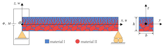
Figure 1.
Magneto-electro-elastic functionally graded porous microbeam configuration.
For the current MEEFGP Timoshenko beam shown in Figure 1, the displacement fields are given by:
where u1, u2, and u3 are the beam displacements; and are the extensional and bending displacements, respectively; represents the rotation angle.
Based on the MCST [29,30], the infinitesimal strain εij and symmetric curvature 𝜒ij can be defined by:
with εijk being the Levi–Civita symbol.
Substituting Equation (4) into Equations (5) and (6) yields:
The electric potential Φ and magnetic potential M in the MEEFGP microbeam model can be assumed as first-order functions of the z-coordinate [56,57,58]:
In addition, the components of the electric field intensity Ek and the components of the magnetic field intensity Hk are given by:
From Equations (9) and (10) can be rewritten as:
By applying the extended MCST [45,59], the constitutive equations for transversely isotropic MEE materials are expressed as [43,45,60,61]:
Based on Equations (7), (8), (11) and (12), the constitutive equations in Equations (13)–(16) can be obtained as:
Based on Equations (7), (8), (11), (12) and (17)–(20), the first variation in the total potential energy U in the current-deformed MEEFGP microbeam satisfying the extended MCST takes the form of [43,45]:
where A is the area of the current beam section.
The first variation in the kinetic energy of the current microbeam can be obtained as [62]:
where ρ(z) is the mass density of the current beam model.
In addition, the virtual work of the external force applied on the beam can be given as [63,64]:
where q is the z-component of the body force per unit length along the x-axis.
Based on Hamilton’s principle [62,64]:
Substituting Equations (21)–(23) into Equation (24), applying the fundamental lemma of the calculus of variations [65], leads to the equations of motion with the arbitrary nature of , , , δϕ(0), δϕ(1), δφ(0), and δφ (1):
And the boundary conditions can be written as:
where the overhead bar denotes the prescribed value, and the stress, electric, magnetic resultants, and mass inertias are defined as:
where ks denotes the shape correction factor, which considers the nonuniformity of εxz over the beam thickness [57,66], and the stiffness coefficients mentioned above are given in Appendix A.
With the help of Equations (25)–(31) and (40)–(50), the equilibrium equations can be expressed as:
3. Analytical Solution
In order to illustrate the new MEEFGP microbeam model developed in Section 2, the static bending and wave propagation problems of the current beam are solved in this section.
According to Equations (25)–(31), the relevant boundary conditions of the simply supported beam can be expressed as:
3.1. Static Bending
For static bending problems, the elastic displacements and the electric and magnetic potential are independent of time t; thus, all terms related to time in Equations (25)–(31) and (51)–(57) can be ignored. Here, we consider Fourier solutions for , , , ϕ(0), ϕ(1), φ(0), and φ (1):
where , , , Φ(0), Φ(1), Ψ(0), and Ψ (1) are the undetermined amplitudes. Note that the assumptions of the solution in Equation (66) satisfy the boundary conditions of the simple supported beam in Equations (58)–(65). In the case of static bending, a uniform load q(x) can also be expanded by the Fourier series:
where the Fourier coefficient Qk calculated by q(x) = p0 is defined as:
By solving the linear algebraic equation system given in Equation (69), the amplitudes can be obtained. Here, we substitute the values of amplitudes into Equation (66), mean the solution of displacement field and electrical and magnetic potentials can be given.
3.2. Wave Propagation
In the wave propagation problem of the current model, the external force vanishes (i.e., q = 0) and the wave propagation properties due to extension (), shear (), and flexure () can be investigated. Here, we consider the following waves for the elastic displacements and the electric and magnetic potential of the MEEFGP microbeam with infinite length:
where ω is the wave frequency and , , , , , , and are the undetermined amplitudes.
Introducing Equation (71) to Equations (51)–(57) yields:
where K is a 7 by 7 matrix, the components of which are given in Equation (70), and:
In order to develop the dispersion relations of wave propagation in the current MEEFGP microbeam, this requires:
Given a group of wave numbers, the wave frequencies satisfying Equation (74) can be determined. Then, fourteen dispersion relations can be identified in this way. By substituting a group of wave numbers and wave frequency that satisfies one of the dispersion relations in Equation (72), the ratios between the five unknown wave amplitudes in Equation (71) can be determined.
4. Numerical Results
The properties of material I and material II are given in Table 1. Material I in the current beam is considered as 50–50% BaTiO3-CoFe2O4 [43,45,67,68,69], and epoxy [70] is adopted for material II. The uniform load p0 is 1/2000h N/m, and the shear correction factor ks introduced to describe the nonuniformity shear strain is 0.80.5 [43,71]. The cross-sectional shape is taken as a rectangle with the aspect ratios b/h = 2 and L/h = 20.

Table 1.
The properties of material I and material II.
In order to verify the correctness of the new model, a comparative study of the deflection of a simply supported beam subjected to a uniform load between the current model without magneto-electric-elastic coupling and the relevant FEM model developed by COMSOL Multiphysics without microstructure effects are plotted in Figure 2. Since COMSOL Multiphysics cannot simulate the model made using magneto-electric-elastic materials, the magnetic and electric material properties are set to 0 in the comparison.
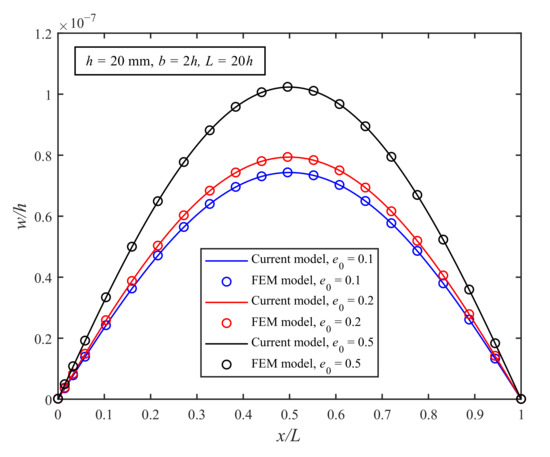
Figure 2.
Comparison of the deflections of the simply supported microbeam model applied to a uniform load.
From Figure 2, it can be found that the numerical results of the current elastic model are the same as those of the FEM model at the macroscale for all three cases. The results not only validate the current model but also show that the deflection will increase with the increase in the content of material II, as expected. The microstructure effect is not obvious for models at the macroscale.
4.1. Static Bending
Figure 3 shows the distribution of the deformation, axial normal stress, and electric and magnetic potentials of the current MEEFGP microbeam model. The beam thickness h is 20 μm, the porosity coefficient e0 is 0.5, and the uniform load p0 is 1/2000h N/m.
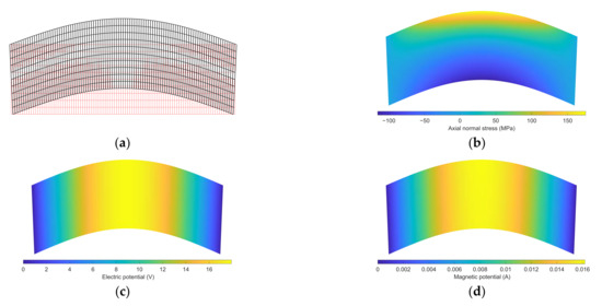
Figure 3.
Distribution of (a) deformation, (b) axial normal stress, (c) electric potential, and (d) magnetic potential (porosity coefficient e0 = 0.5).
From Figure 3b, it can be found that the axial normal stress values at the bottom and top of the current model are larger, and there is little difference in their absolute values. This is due to the fact that the current beam is not a homogeneous material, the porosity of the bottom layer of the beam is higher, and this layer contains more epoxy. If the porosity coefficient is higher, the difference in the absolute value of axial normal stress between the bottom and top layers of the current beam will be larger. From Figure 3c,d, it is clear that the electric and magnetic potential distributions in the current model are similar. The electric and magnetic potentials change uniformly in the x-direction.
Figure 4a,b show the deflections and rotation angles of the MEEFGP microbeam with the different thicknesses of the current and classical models. The porosity coefficient is fixed at 0.5. The results of the current model taking the modified couple stress effect into account (with A11 ≠ 0 and A12 ≠ 0) are directly obtained from Equations (66) and (69), while the results of the classical model without considering the microstructure effect (with A11 = 0 and A12 = 0) are obtained from the same equations.
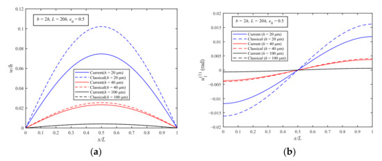
Figure 4.
Deflection (a) and rotation (b) of the MEEFGP simply supported microbeam (porosity coefficient = 0.5).
From Figure 4a,b, it can be seen that the deflections and rotation angles of the current model are always smaller than those of the classical model due to the modified couple stress effect. As the thickness increases, the influence of the modified couple stress effect on the results of the current model becomes small, and the difference between the numerical results predicted by the current model and the classical model decreases.
Figure 5a,b display the electric and magnetic potentials of the MEEFGP simply supported beam with different thicknesses. The numerical results of the current and classical model are calculated using Equations (9), (66) and (69). The porosity coefficient is also fixed at 0.5.
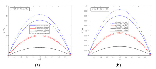
Figure 5.
Electric potential (a) and magnetic potential (b) of the MEEFGP simply supported microbeam (porosity coefficient = 0.5).
From Figure 5a,b, it can be found that the magnitudes of the electric and magnetic potentials predicted by the current model are always different to those predicted by the classical model; while h increases, the differences between the results of the two models become small. This phenomenon verifies that for extremely thin beams, the microstructure effect is significant.
In order to investigate the inhomogeneity of material properties, Figure 6 shows the maximum deflections wmax (x = L/2) of the MEEFGP beam with different porosity coefficients e0 for beam thicknesses h = 20 μm and h = 20 mm. From Figure 6a, it is clear that the maximum deflections wmax of both the current and classical models increase with the increase in porosity coefficient e0, and the numerical results of the current model are always smaller than those of the classical model. In addition, when e0 is equal to 1, the content of the material II is the largest, due to the low stiffness of material II, the maximum deflection wmax reaches the maximum value. From Figure 6b, it can be seen that there is almost no difference in wmax between the two models when the beam thickness is large enough. Additionally, from Figure 6a,b, the porosity coefficient e0 has an important effect on the static bending response at all length scales.
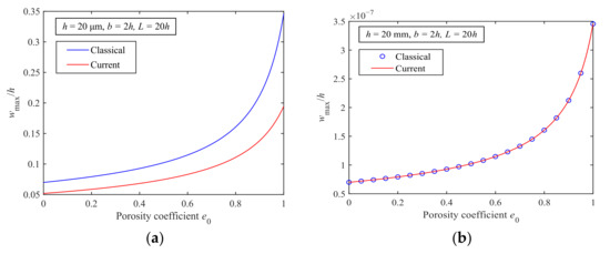
Figure 6.
Maximum deflections of the MEEFGP microbeam for different porosity coefficients with (a) h = 20 μm and (b) h = 20 mm.
4.2. Wave Propagation
Based on Equations (71)–(74), only three out of the fourteen dispersion relations possess positive real wave frequencies. These are identified as the dispersion relations due to the shear, extensional, and flexural waves.
Figure 7 shows the dispersion curves of the current and classical MEEFGP models with the porosity coefficient e0 equal to 0.5. For convenience of comparison, the wave number and wave frequency have been nondimensionalized:
where T is equal to 10−9 s and ξ is the wave number, which is expressed as:
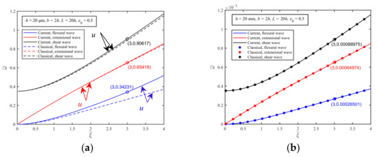
Figure 7.
The dispersion curves due to the shear, extensional, and flexural waves for the current and classical MEEFGP models (e0 = 0.5) with thicknesses of (a) h = 20 μm and (b) h = 20 mm.
From Figure 7a,b, the conclusion that the microstructure effects are only significant for structures at the microscale is confirmed again.
To investigate the mode of the shear, extensional, and flexural waves in the current MEEFGP model with the modified couple stress effect, the dimensionless wave number is fixed as = 3. Then, three dimensionless wave frequencies can be determined from Figure 7a. The three wave number and wave frequency groups before dimensionization are given by:
Then, the deformation shape, electric potential, and magnetic potential distribution of the current MEEFGP microbeam can be obtained.
Figure 8a shows the deformation and electric potential of the point on the shear dispersion curve shown in Figure 7a. From Figure 8a, it can be seen that the model shows obvious shear deformation. Additionally, the electric potential mainly varies along the x-direction.
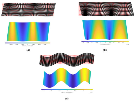
Figure 8.
Distribution of the deformation and electric potential values of the (a) shear wave, (b) extensional wave, and (c) flexural wave.
Figure 8b shows the deformation and electric potential of the point on the extensional dispersion curve shown in Figure 7a. From Figure 8b, it can be observed that the deformation is mainly caused by axial extension. In addition, because of the inhomogeneity of the material, the extensional deformation of the beam shows differences in the z-direction. The distribution of the electric potential is also nonuniform.
5. Conclusions
By using the extended modified couple stress theory, a new magneto-electro-elastic functionally graded porous microbeam was developed. Based on Hamilton’s principle, the equations of motion and complete boundary conditions of the new model were formulated by applying the variational approach. The magnetic, electric, and elastic field coupling effects and the microstructure effect were considered in the new model. For the purpose of examining the current beam, the numerical results of the static bending and wave propagation of a simply supported microbeam were obtained.
For the static bending response, the new model was subjected to uniformly distributed loads. The parametric studies proved that the numerical results predicted by the extended modified couple stress effects of the deflection, rotation angle, electric potential, and magnetic potential were conspicuously influenced by the microstructure effect, and that the classical theory is not suitable for structures at the microscale. However, as the size of the model increased, there was almost no difference between the results predicted by the extended modified couple stress theory and the classical theory. In addition, by changing the porosity coefficient e0, the material distribution of the model can be controlled, meaning the deformation shape and electric and magnetic potentials can be optimized.
For the problem of wave propagation, the wave frequencies predicted by the extended modified couple stress theory were always higher than those predicted by the classical theory, while the microstructure effect was not obvious when the beam size was large enough. These phenomena indicate that the microstructure effect tends to make the microbeam stiffer. Additionally, the porosity coefficient e0 can also change the wave propagation properties. These findings are able to provide not only information for the design and optimization of MEMS and NEMS devices made using MEEFGP materials, but also the theoretical basis for the development of microacoustic wave devices.
Author Contributions
Conceptualization, J.H. and G.Z.; methodology, J.H. and S.W.; writing—original draft preparation, S.W. and X.Q. All authors have read and agreed to the published version of the manuscript.
Funding
The work reported here was funded by the National Key R&D Program of China (grant number 2018YFD1100401), the National Natural Science Foundation of China (grant numbers 12002086, 11872149, and 11772091), the Zhishan Youth Scholar Program of SEU, and the Fundamental Research Funds for the Central Universities.
Data Availability Statement
Not applicable.
Conflicts of Interest
The authors declare no conflict of interest.
Appendix A
References
- Sahmani, S.; Aghdam, M.M. Nonlocal Strain Gradient Shell Model for Axial Buckling and Postbuckling Analysis of Magneto-Electro-Elastic Composite Nanoshells. Compos. Part. B Eng. 2018, 132, 258–274. [Google Scholar] [CrossRef]
- Farajpour, M.R.; Shahidi, A.R.; Hadi, A.; Farajpour, A. Influence of Initial Edge Displacement on the Nonlinear Vibration, Electrical and Magnetic Instabilities of Magneto-Electro-Elastic Nanofilms. Mech. Adv. Mater. Struct. 2019, 26, 1469–1481. [Google Scholar] [CrossRef]
- Yakhno, V.G. An Explicit Formula for Modeling Wave Propagation in Magneto-Electro-Elastic Materials. J. Electromagn. Waves Appl. 2018, 32, 899–912. [Google Scholar] [CrossRef]
- Reddy, J.N. Microstructure-Dependent Couple Stress Theories of Functionally Graded Beams. J. Mech. Phys. Solids 2011, 59, 2382–2399. [Google Scholar] [CrossRef]
- Taati, E. Analytical Solutions for the Size Dependent Buckling and Postbuckling Behavior of Functionally Graded Micro-Plates. Int. J. Eng. Sci. 2016, 100, 45–60. [Google Scholar] [CrossRef]
- Şimşek, M. Buckling of Timoshenko Beams Composed of Two-Dimensional Functionally Graded Material (2D-FGM) Having Different Boundary Conditions. Compos. Struct. 2016, 149, 304–314. [Google Scholar] [CrossRef]
- Liu, J.; He, B.; Ye, W.; Yang, F. High Performance Model for Buckling of Functionally Graded Sandwich Beams Using a New Semi-Analytical Method. Compos. Struct. 2021, 262, 113614. [Google Scholar] [CrossRef]
- Akbarzadeh, A.H.; Abedini, A.; Chen, Z.T. Effect of Micromechanical Models on Structural Responses of Functionally Graded Plates. Compos. Struct. 2015, 119, 598–609. [Google Scholar] [CrossRef]
- Akbarzadeh, A.; Chen, Z. Thermo-Magneto-Electro-Elastic Responses of Rotating Hollow Cylinders. Mech. Adv. Mater. Struct. 2014, 21, 67–80. [Google Scholar] [CrossRef]
- Zhu, J.; Lai, Z.; Yin, Z.; Jeon, J.; Lee, S. Fabrication of ZrO2–NiCr Functionally Graded Material by Powder Metallurgy. Mater. Chem. Phys. 2001, 68, 130–135. [Google Scholar] [CrossRef]
- Peng, X.; Yan, M.; Shi, W. A New Approach for the Preparation of Functionally Graded Materials via Slip Casting in a Gradient Magnetic Field. Scr. Mater. 2007, 56, 907–909. [Google Scholar] [CrossRef]
- Kiran, M.C.; Kattimani, S.C.; Vinyas, M. Porosity Influence on Structural Behaviour of Skew Functionally Graded Magneto-Electro-Elastic Plate. Compos. Struct. 2018, 191, 36–77. [Google Scholar] [CrossRef]
- Vinyas, M. On Frequency Response of Porous Functionally Graded Magneto-Electro-Elastic Circular and Annular Plates with Different Electro-Magnetic Conditions Using HSDT. Compos. Struct. 2020, 240, 112044. [Google Scholar] [CrossRef]
- Ebrahimi, F.; Jafari, A.; Selvamani, R. Thermal Buckling Analysis of Magneto-Electro-Elastic Porous FG Beam in Thermal Environment. Adv. Nano Res. 2020, 8, 83–94. [Google Scholar] [CrossRef]
- Vinyas, M.; Dineshkumar, H. Large Deflection Analysis of Functionally Graded Magneto-Electro-Elastic Porous Flat Panels. Eng. Comput. 2021, 1–20. [Google Scholar] [CrossRef]
- Sh, E.L.; Kattimani, S.; Vinyas, M. Nonlinear Free Vibration and Transient Responses of Porous Functionally Graded Magneto-Electro-Elastic Plates. Arch. Civ. Mech. Eng. 2022, 22, 38. [Google Scholar] [CrossRef]
- Zhu, C.S.; Fang, X.Q.; Liu, J.X. Surface Energy Effect on Buckling Behavior of the Functionally Graded Nano-Shell Covered with Piezoelectric Nano-Layers under Torque. Int. J. Mech. Sci. 2017, 133, 662–673. [Google Scholar] [CrossRef]
- Qu, Y.; Jin, F.; Zhang, G. Mechanically Induced Electric and Magnetic Fields in the Bending and Symmetric-Shear Deformations of a Microstructure-Dependent FG-MEE Composite Beam. Compos. Struct. 2021, 278, 114554. [Google Scholar] [CrossRef]
- Lam, D.C.C.; Yang, F.; Chong, A.C.M.; Wang, J.; Tong, P. Experiments and Theory in Strain Gradient Elasticity. J. Mech. Phys. Solids 2003, 51, 1477–1508. [Google Scholar] [CrossRef]
- Mcfarland, A.W.; Colton, J.S. Role of Material Microstructure in Plate Stiffness with Relevance to Microcantilever Sensors. J. Micromech. Microeng. 2005, 15, 1060. [Google Scholar] [CrossRef]
- Eringen, A.C. On Differential Equations of Nonlocal Elasticity and Solutions of Screw Dislocation and Surface Waves. J. Appl. Phys. 1983, 54, 4703–4710. [Google Scholar] [CrossRef]
- Toupin, R.A. Elastic Materials with Couple-Stresses. Arch. Ration. Mech. Anal. 1962, 11, 385–414. [Google Scholar] [CrossRef] [Green Version]
- Mindlin, R.D. Influence of Couple-Stresses on Stress Concentrations. Exp. Mech. 1963, 3, 1–7. [Google Scholar] [CrossRef]
- Kolter, W.T. Couple Stresses in the Theory of Elasticity: I and II. Proc. K. Ned. Akad. Wet. B 1964, 67, 17–44. [Google Scholar]
- Mindlin, R.D. Micro-Structure in Linear Elasticity. Arch. Ration. Mech. Anal. 1964, 16, 51–78. [Google Scholar] [CrossRef]
- Mindlin, R.D.; Eshel, N.N. On First Strain-Gradient Theories in Linear Elasticity. Int. J. Solids Struct. 1968, 4, 109–124. [Google Scholar] [CrossRef]
- Polizzotto, C.A. Hierarchy of Simplified Constitutive Models within Isotropic Strain Gradient Elasticity. Eur. J. Mech.—A/Solids 2017, 61, 92–109. [Google Scholar] [CrossRef]
- Altan, B.S.; Aifantis, E.C. On Some Aspects in the Special Theory of Gradient Elasticity. J. Mech. Behav. Mater. 1997, 8, 231–282. [Google Scholar] [CrossRef]
- Yang, F.; Chong, A.C.M.; Lam, D.C.C.; Tong, P. Couple Stress Based Strain Gradient Theory for Elasticity. Int. J. Solids Struct. 2002, 39, 2731–2743. [Google Scholar] [CrossRef]
- Park, S.K.; Gao, X.L. Variational Formulation of a Modified Couple Stress Theory and Its Application to a Simple Shear Problem. Z. Angew. Math. Phys. 2008, 59, 904–917. [Google Scholar] [CrossRef]
- Zhang, G.Y.; Gao, X.L. A New Bernoulli–Euler Beam Model Based on a Reformulated Strain Gradient Elasticity Theory. Math. Mech. Solids 2020, 25, 630–643. [Google Scholar] [CrossRef]
- Qu, Y.L.; Zhang, G.Y.; Fan, Y.M.; Jin, F. A Non-Classical Theory of Elastic Dielectrics Incorporating Couple Stress and Quadrupole Effects: Part I—Reconsideration of Curvature-Based Flexoelectricity Theory. Math. Mech. Solids 2021, 26, 1647–1659. [Google Scholar] [CrossRef]
- Zhang, G.Y.; Gao, X.L.; Zheng, C.Y.; Mi, C.W. A Non-Classical Bernoulli-Euler Beam Model Based on a Simplified Micromorphic Elasticity Theory. Mech. Mater. 2021, 161, 103967. [Google Scholar] [CrossRef]
- Ebrahimi, F.; Barati, M.R. Vibration Analysis of Embedded Biaxially Loaded Magneto-Electrically Actuated Inhomogeneous Nanoscale Plates. J. Vib. Control. 2018, 24, 3587–3607. [Google Scholar] [CrossRef]
- Kiani, A.; Sheikhkhoshkar, M.; Jamalpoor, A.; Khanzadi, M. Free Vibration Problem of Embedded Magneto-Electro-Thermo-Elastic Nanoplate Made of Functionally Graded Materials via Nonlocal Third-Order Shear Deformation Theory. J. Intell. Mater. Syst. Struct. 2018, 29, 741–763. [Google Scholar] [CrossRef]
- Liu, H.; Lv, Z. Vibration Performance Evaluation of Smart Magneto-Electro-Elastic Nanobeam with Consideration of Nanomaterial Uncertainties. J. Intell. Mater. Syst. Struct. 2019, 30, 2932–2952. [Google Scholar] [CrossRef]
- Xiao, W.S.; Gao, Y.; Zhu, H. Buckling and Post-Buckling of Magneto-Electro-Thermo-Elastic Functionally Graded Porous Nanobeams. Microsyst. Technol. 2019, 25, 2451–2470. [Google Scholar] [CrossRef]
- Lim, C.W.; Zhang, G.; Reddy, J.N. A Higher-Order Nonlocal Elasticity and Strain Gradient Theory and Its Applications in Wave Propagation. J. Mech. Phys. Solids 2015, 78, 298–313. [Google Scholar] [CrossRef]
- Şimşek, M. Nonlinear Free Vibration of a Functionally Graded Nanobeam Using Nonlocal Strain Gradient Theory and a Novel Hamiltonian Approach. Int. J. Eng. Sci. 2016, 105, 12–27. [Google Scholar] [CrossRef]
- Li, X.; Li, L.; Hu, Y.; Ding, Z.; Deng, W. Bending, Buckling and Vibration of Axially Functionally Graded Beams Based on Nonlocal Strain Gradient Theory. Compos. Struct. 2017, 165, 250–265. [Google Scholar] [CrossRef]
- Gao, X.L.; Zhang, G.Y. A Microstructure- and Surface Energy-Dependent Third-Order Shear Deformation Beam Model. Z. Angew. Math. Phys. 2015, 66, 1871–1894. [Google Scholar] [CrossRef]
- Yu, T.; Hu, H.; Zhang, J.; Bui, T.Q. Isogeometric Analysis of Size-Dependent Effects for Functionally Graded Microbeams by a Non-Classical Quasi-3D Theory. Thin Walled Struct. 2019, 138, 1–14. [Google Scholar] [CrossRef]
- Zhang, G.Y.; Qu, Y.L.; Gao, X.L.; Jin, F. A Transversely Isotropic Magneto-Electro-Elastic Timoshenko Beam Model Incorporating Microstructure and Foundation Effects. Mech. Mater. 2020, 149, 103412. [Google Scholar] [CrossRef]
- Hong, J.; Wang, S.P.; Zhang, G.Y.; Mi, C.W. On the Bending and Vibration Analysis of Functionally Graded Magneto-Electro-Elastic Timoshenko Microbeams. Crystals 2021, 11, 1206. [Google Scholar] [CrossRef]
- Qu, Y.L.; Li, P.; Zhang, G.Y.; Jin, F.; Gao, X.L. A Microstructure-Dependent Anisotropic Magneto-Electro-Elastic Mindlin Plate Model Based on an Extended Modified Couple Stress Theory. Acta Mech. 2020, 231, 4323–4350. [Google Scholar] [CrossRef]
- Shen, W.; Zhang, G.; Gu, S.; Cong, Y. A Transversely Isotropic Magneto-Electro-Elastic Circular Kirchhoff Plate Model Incorporating Microstructure Effect. Acta Mech. Solida Sin. 2022, 35, 185–197. [Google Scholar] [CrossRef]
- Qu, Y.L.; Jin, F.; Yang, J.S. Magnetically Induced Charge Motion in the Bending of A Beam with Flexoelectric Semiconductor and Piezomagnetic Dielectric Layers. J. Appl. Phys. 2021, 127, 064503. [Google Scholar] [CrossRef]
- Zhu, F.; Ji, S.; Zhu, J.; Qian, Z.; Yang, J. Study on the Influence of Semiconductive Property for the Improvement of Nanogenerator by Wave Mode Approach. Nano Energy 2018, 52, 474–484. [Google Scholar] [CrossRef]
- Shingare, K.B.; Kundalwal, S.I. Static and Dynamic Response of Graphene Nanocomposite Plates with Flexoelectric Effect. Mech. Mater. 2019, 134, 69–84. [Google Scholar] [CrossRef]
- Wang, L.; Liu, S.; Feng, X.; Zhang, C.; Zhu, L.; Zhai, J.; Qin, Y.; Wang, Z.L. Flexoelectronics of Centrosymmetric Semiconductors. Nat. Nanotechnol. 2020, 15, 661–667. [Google Scholar] [CrossRef]
- Sharma, S.; Kumar, A.; Kumar, R.; Talha, M.; Vaish, R. Geometry Independent Direct and Converse Flexoelectric Effects in Functionally Graded Dielectrics: An Isogeometric Analysis. Mech. Mater. 2020, 148, 103456. [Google Scholar] [CrossRef]
- Chen, D.; Yang, J.; Kitipornchai, S. Elastic Buckling and Static Bending of Shear Deformable Functionally Graded Porous Beam. Compos. Struct. 2015, 133, 54–61. [Google Scholar] [CrossRef] [Green Version]
- Chen, D.; Yang, J.; Kitipornchai, S. Free and Forced Vibrations of Shear Deformable Functionally Graded Porous Beams. Int. J. Mech. Sci. 2016, 108, 14–22. [Google Scholar] [CrossRef] [Green Version]
- Heshmati, M.; Daneshmand, F. A Study on the Vibrational Properties of Weight-Efficient Plates Made of Material with Functionally Graded Porosity. Compos. Struct. 2018, 200, 229–238. [Google Scholar] [CrossRef]
- Zhang, G.Y.; Gao, X.L. Band Gaps for Wave Propagation in 2-D Periodic Three-Phase Composites with Coated Star-Shaped Inclusions and an Orthotropic Matrix. Compos. Part B Eng. 2020, 182, 107319. [Google Scholar] [CrossRef]
- Mindlin, R.D. High Frequency Vibrations of Piezoelectric Crystal Plates. Int. J. Solids Struct. 1972, 8, 895–906. [Google Scholar] [CrossRef]
- Yang, J. The Mechanics of Piezoelectric Structures; World Scientific: Singapore, 2006. [Google Scholar] [CrossRef]
- Qu, Y.; Jin, F.; Yang, J. Effects of Mechanical Fields on Mobile Charges in a Composite Beam of Flexoelectric Dielectrics and Semiconductors. J. Appl. Phys. 2020, 127, 194502. [Google Scholar] [CrossRef]
- Zhang, G.Y.; Gao, X.L.; Guo, Z.Y. A Non-Classical Model for an Orthotropic Kirchhoff Plate Embedded in a Viscoelastic Medium. Acta Mech. 2017, 228, 3811–3825. [Google Scholar] [CrossRef]
- Han, X.; Pan, E. Fields Produced by Three-Dimensional Dislocation Loops in Anisotropic Magneto-Electro-Elastic Materials. Mech. Mater. 2013, 59, 110–125. [Google Scholar] [CrossRef]
- Kumar, D.; Sarangi, S.; Saxena, P. Universal Relations in Coupled Electro-Magneto-Elasticity. Mech. Mater. 2020, 143, 103308. [Google Scholar] [CrossRef]
- Ma, H.M.; Gao, X.L.; Reddy, J.N. A Microstructure-Dependent Timoshenko Beam Model Based on a Modified Couple Stress Theory. J. Mech. Phys. Solids 2008, 56, 3379–3391. [Google Scholar] [CrossRef]
- Hong, J.; Wang, S.P.; Zhang, G.Y.; Mi, C.W. Bending, Buckling and Vibration Analysis of Complete Microstructure-Dependent Functionally Graded Material Microbeams. Int. J. Appl. Mech. 2021, 13, 2150057. [Google Scholar] [CrossRef]
- Reddy, J.N. Energy Principles and Variational Methods in Applied Mechanics, 2nd ed.; Wiley: New York, NY, USA, 2002. [Google Scholar]
- Gao, X.L.; Mall, S. Variational Solution for a Cracked Mosaic Model of Woven Fabric Composites. Int. J. Solids Struct. 2001, 38, 855–874. [Google Scholar] [CrossRef]
- Yang, J. An Introduction to the Theory of Piezoelectricity; Springer: New York, NY, USA, 2005. [Google Scholar] [CrossRef]
- Li, J.Y. Magnetoelectroelastic Multi-Inclusion and Inhomogeneity Problems and Their Applications in Composite Materials. Int. J. Eng. Sci. 2000, 38, 1993–2011. [Google Scholar] [CrossRef]
- Sih, G.C.; Song, Z.F. Magnetic and Electric Poling Effects Associated with Crack Growth in BaTiO3–CoFe2O4 Composite. Theor. Appl. Fract. Mech. 2003, 39, 209–227. [Google Scholar] [CrossRef]
- Wang, Y.; Xu, R.; Ding, H. Axisymmetric Bending of Functionally Graded Circular Magneto-Electro-Elastic Plates. Eur. J. Mech. A/Solids 2011, 30, 999–1011. [Google Scholar] [CrossRef]
- Zhang, G.Y.; Gao, X.L. Elastic Wave Propagation in 3-D Periodic Composites: Band Gaps Incorporating Microstructure Effects. Compos. Struct. 2018, 204, 920–932. [Google Scholar] [CrossRef]
- Ma, H.M.; Gao, X.L.; Reddy, J.N. A Non-Classical Mindlin Plate Model Based on a Modified Couple Stress Theory. Acta Mechanica 2011, 220, 217–235. [Google Scholar] [CrossRef]
Publisher’s Note: MDPI stays neutral with regard to jurisdictional claims in published maps and institutional affiliations. |
© 2022 by the authors. Licensee MDPI, Basel, Switzerland. This article is an open access article distributed under the terms and conditions of the Creative Commons Attribution (CC BY) license (https://creativecommons.org/licenses/by/4.0/).