Article

Effect of Hollow Body Material on Mechanical Properties of Bubble Concrete

1
Department of Civil and Architectural Engineering, Kyushu Institute of Technology, Kitakyushu 804-8550, Japan
2
Department of Civil and Environmental Engineering, University Technology PETRONAS (U.T.P.), Bandar Seri Iskandar 32610, Malaysia
3
Graduate School of Environmental Study, Nagoya University, Nagoya 464-8601, Japan
*
Author to whom correspondence should be addressed.
Crystals 2022, 12(5), 708; https://doi.org/10.3390/cryst12050708
Submission received: 8 April 2022 / Revised: 10 May 2022 / Accepted: 14 May 2022 / Published: 16 May 2022

Abstract

:
The bubble concrete (BC) produced by mixing high-strength hollow bodies into concrete has been proven to be effective in reducing density while maintaining strength. It has been verified that the position distribution of hollow bodies inside hardened BC significantly affects the compressive strength of the BC. However, the effect of hollow body material on the strength of BC has not yet been established. In the present paper, through concrete compression experiments and the nonlinear finite element analysis (F.E.A.), a comparative study of BC with three different hollow bodies—steel spheres, sand bonded stainless steel spheres, and ceramic spheres—has been carried out. The results show that the difference in elastic modulus of hollow bodies and concrete is the primary reason for the inhomogeneous stress distribution inside the concrete. The interface between the hollow body and hardened concrete could be increased using epoxy resin, thus enhancing the compressive strength of BC specimens by 26.6% compared to control concrete. The ceramic material is tightly integrated with the concrete, but as a brittle material, the ceramic cannot sustain colossal stress and subsequently breaks down.

1. Introduction

Lightweight concrete materials can be manufactured for various applications by adding lightweight admixtures to the concrete [1,2], such as diatomaceous earth [3], expanded polystyrene foam [4], sintered fly ash [5], expanded clay [6,7], expanded shale [8], et cetera. Traditionally, concrete is a three-phase composite material consisting of cement paste, aggregate, and aggregate/cement paste interface [9,10]. Aggregates usually make up 70–80% of the volume of Portland cement concrete, and greatly affect the mechanical properties, water absorption, thermal conductivity, et cetera. [2,4]. Aggregates are the weakest part of concrete composites, and the greater the strength of aggregates, the higher the strength of concrete. For instance, by calcining or adding ingredients, it is possible to improve the strength and durability to obtain structural concrete with a density of less than 1840 kg/m3 [11,12]. However, most fillers inside lightweight aggregate concrete only bear little to no stress, which merely creates holes inside the concrete [13]. Therefore, many attempts have been made to improve the compressive strength of concrete materials by increasing the strength of aggregates [14,15].
Inspired by hollow bird bones [16], the author Pei-Shan Chen proposed a method to reduce the density of concrete by mixing high-strength hollow bodies into concrete and named it bubble concrete (BC), as shown in Figure 1 [17,18]. As a kind of aggregate, the high-strength hollow bodies are mixed into concrete to reduce concrete density while transferring the stress by means of its shell structure. This method is different from the biaxial hollow slab widely used in Europe and Asia [19,20]. The hollow body used in biaxial hollow slabs is usually made from plastics and creates cavities in concrete but is not able to transmit internal stress [21]. In comparison, the high-strength hollow bodies in BC are used to transmit internal stresses and enhance concrete strength [10,21].
In previous studies [22,23,24,25], the effects of shape, number, and position distribution of the hollow bodies on the mechanical characteristics of BC have been investigated. It was found that the hollow bodies in BC deformed slightly because of transmitting the internal stresses through their shell structure. It is also proved that the BC with regularly distributed spheres had a higher performance in terms of strength and density because it can avoid the mutual extrusion of hollow bodies. However, the low strength of the interface transition zone between the hollow body and the concrete caused the hollow body to separate from the concrete after deformation, and consequently cracks initiated along the seams. The material of hollow bodies greatly affects the strength of the interface transition zone. In the present paper, three different types of hollow body materials are used to investigate the factors affecting the mechanical properties of BC, which are steel spheres (SS), sand bonded stainless steel spheres (SB), and ceramic spheres (CS). The compressive strength, stress distribution, and failure mechanism of the BC will be investigated through concrete compression experiments and the nonlinear mechanical finite element analysis (F.E.A.).

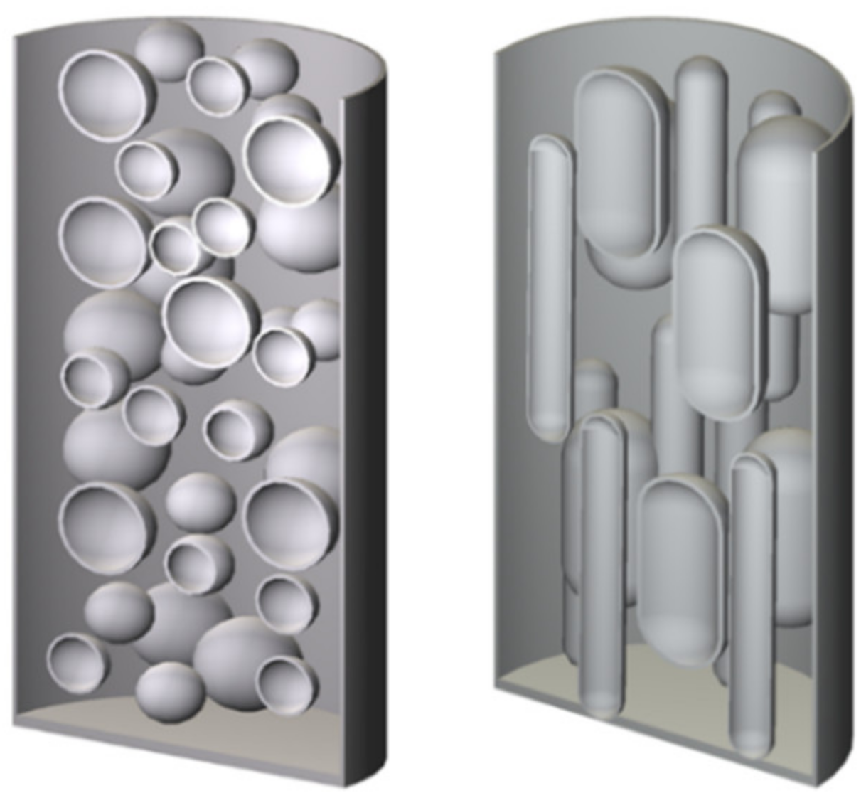
2. Experimental Conditions and Analytical Models

2.1. Concrete Compression Experiment

Cylindrical concrete specimens with a diameter of 150 mm and a height of 300 mm have been prepared according to the Japanese Industrial Standard (JIS) [26]. The target strength of the concrete without hollow bodies was set as 40 N / mm 2 . The concrete is first mixed with the hollow bodies and then filled into the molds in three layers with vibration. The specimens were demolded in 24 h after hardening and cured in water at 20 ± 3 °C for 28 days. At the age of 28 days, the concrete specimens were removed from the curing tank and dried. Strain gauges of 74 mm in length and 8 mm in width were pasted vertically on the center of the specimens, and the compressive load and strains were measured with loading history. The measured strengths of the control concrete were all slightly higher than the target strength of 40 N / mm 2 , because of the wet curing environment [1]. It should be noted that the three BC experiments were completed at different times (Steel spheres: 2008; Sand bonded stainless steel spheres: 2008, 2009; Ceramic spheres: 2008, 2009), therefore the compressive strengths of the control concrete specimens were slightly different.

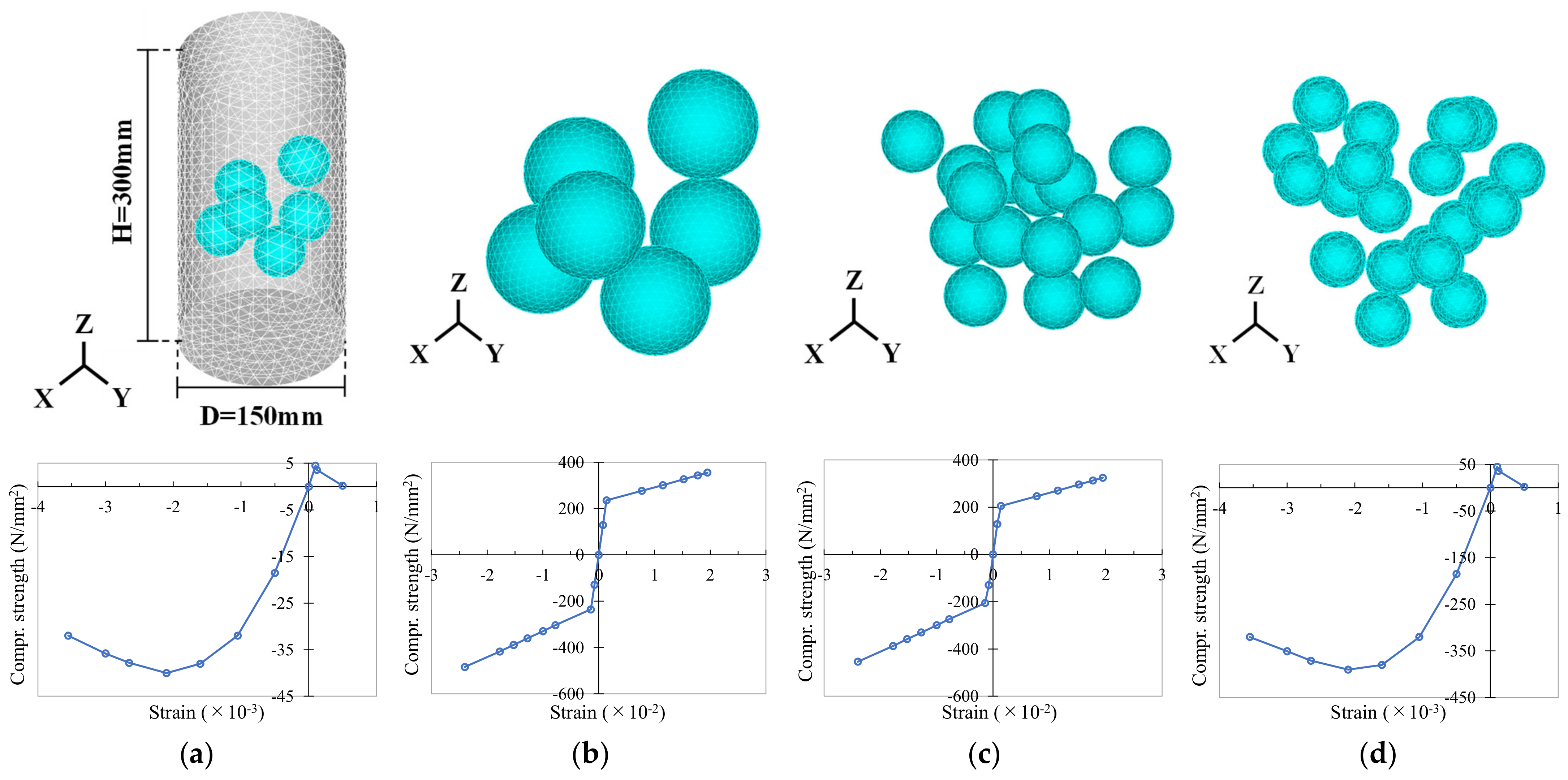
2.2. Finite Element Analysis

The stress distribution inside the BC is simulated using ADINA. Due to the difficulty in simulating the adhesion and friction forces between the hollow body and concrete, the analytical results will be slightly higher than the experimental values. The analytical models and inputted stress–strain curves of the concrete and hollow bodies are shown in Figure 2. The element type is 3D-solid, and the element edge length of the concrete is 15 mm, while for the hollow bodies it is 5 mm, with ten nodes per element. The dimensions of the analytical models for concrete and hollow bodies are the same as the experiments. The maximum compressive strength of the concrete is always equal to the strength of the control concrete in the experiment. A uniform load is applied to the top of the concrete and increases uniformly with time until failure. The concrete bottom is applied with translation and rotation fixation in the XYZ axis. In addition, the primary purpose of the mechanical analysis in this paper is to intuitively find the features of stress distributions inside the BC rather than simulate the real specimen strength. Therefore, only the central 1/3 part incorporating hollow bodies was simulated to save CPU runtime.

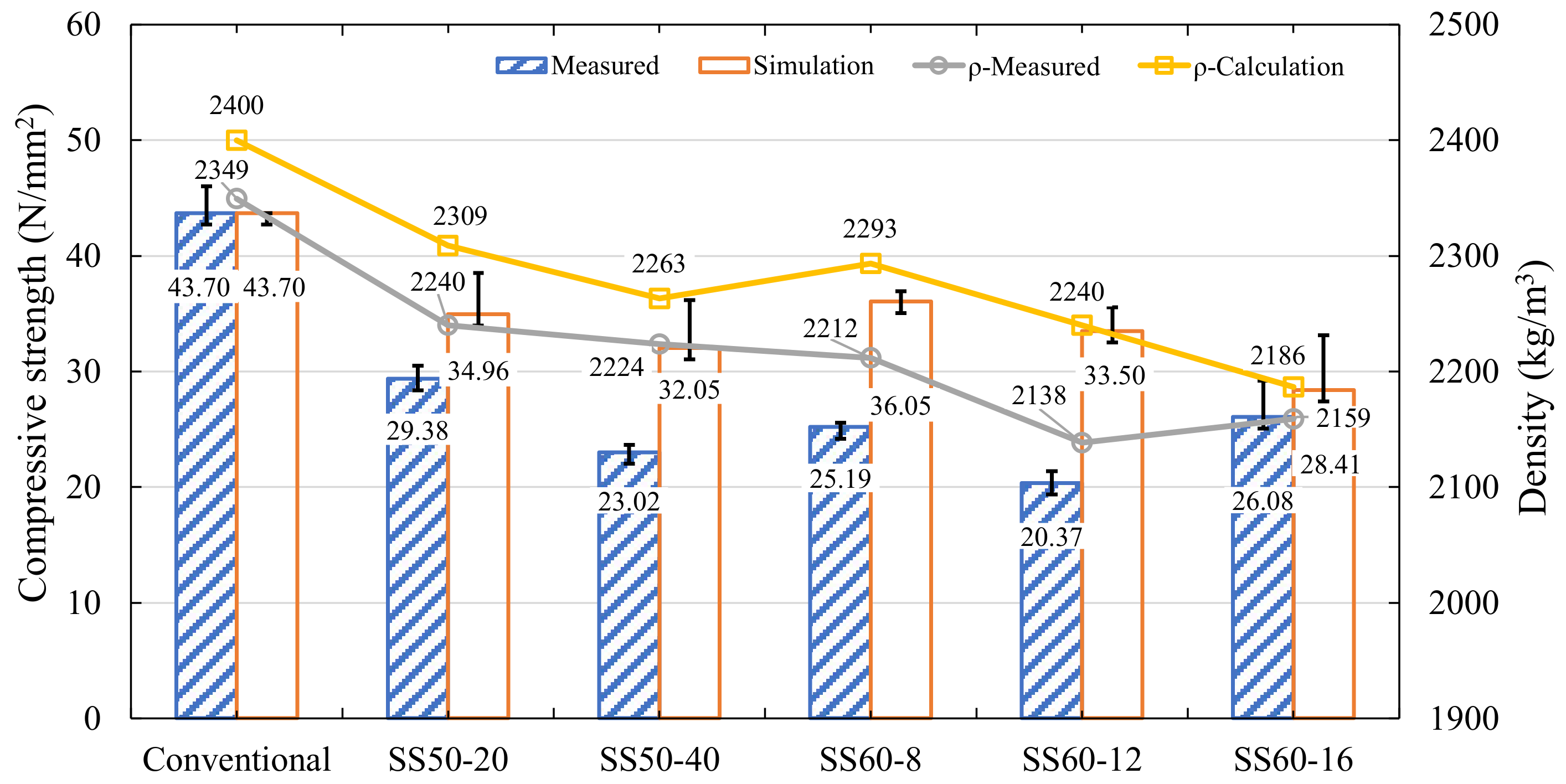
3. Bubble Concrete with Steel Spheres

The mechanical analysis of BC with multiple steel spheres (Named as SS concrete) was well documented [23]. Therefore, this paper focuses on the failure mechanism of the hollow bodies and the interaction of the hollow bodies with concrete material.

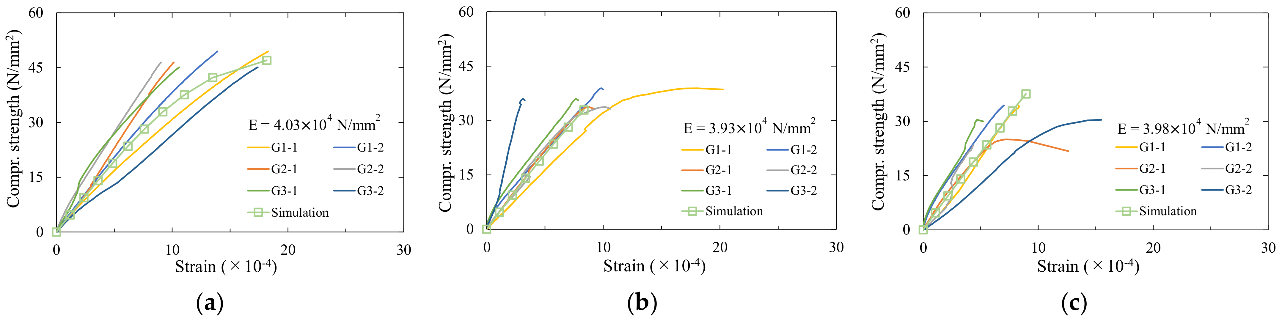
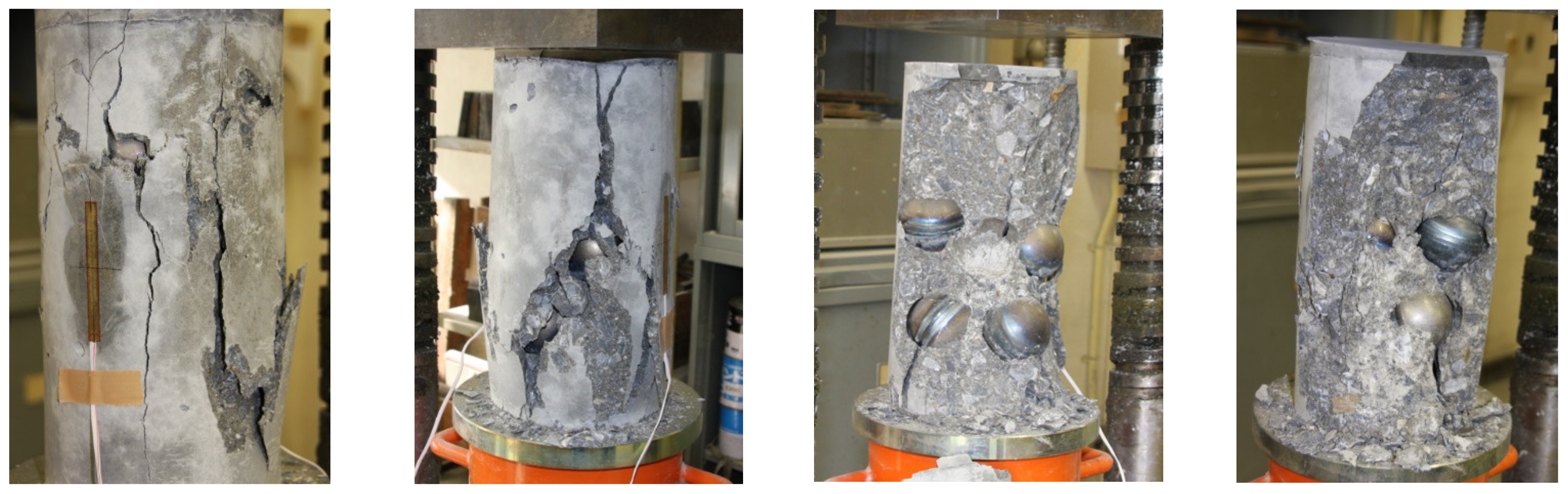
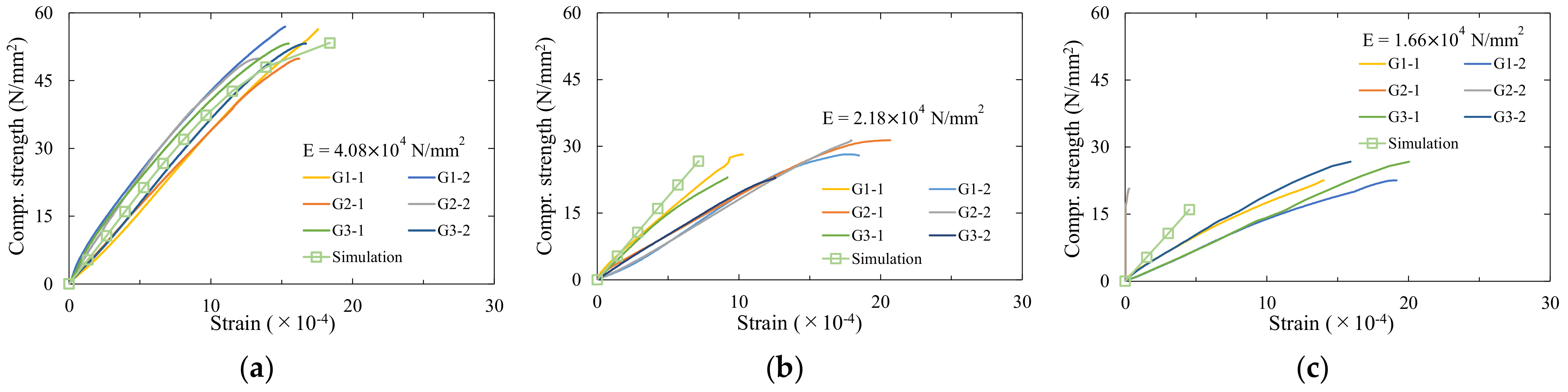
3.1. Concrete Compression Experiment

The hollow bodies used in the experiment were steel spheres welded from two hemispheres with a yield of 235 N / mm 2 according to JIS SS400. As shown in Table 1, the concrete specimens were divided into five groups according to the diameter and number of the hollow bodies, and the three concrete specimens were produced for each group, while five control concrete specimens were used for comparison. The mix proportion (the weight ratio) of concrete paste was water: cement: fine aggregate: coarse aggregate = 160: 454: 740: 1004. The fine aggregate rate was 42.9%. The maximum coarse aggregate size was 20 mm, the water reducing agent was 5.4 kg/m3, and the measured concrete slump flow was 21.5 cm.
As shown in Figure 3, the average strength and average density of conventional were 43.70 N / mm 2 and 2349 kg/m3, respectively. The average strength, density, and elastic modulus of BC were 20.00–26.00 N / mm 2 , 2138–2240 kg/m3, and 2.55–3.78 ×   10 4   N / mm 2 , respectively. The percentage compared with conventional concrete was 45.0–59.0% for strength, 91.0–95.4% for density, and 57.2–84.8% for elastic modulus. As the number of hollow bodies increases, the compressive strength, density, and elastic modulus of specimens decrease. Figure 4 shows the stress–strain curve of concrete. In the figures, the curve lines corresponded to strain gauges pasted on the left side of the specimens are labeled as G∎–1, and those on the right side are labeled as G∎–2.
Figure 5 shows the failure picture of SS concrete. At the initial stage of loading, multiple vertical microcracks were initiated at the outer surface of the cylinder. As the loading increased, the crack width gradually increased and was accompanied by concrete cover fragments spalling. Subsequently, chunks of concrete fall off along the cracks, the specimen reaches its maximum bearing stress, and the concrete fails. Cracks within the concrete grew along the surface of the steel sphere and linked to other steel spheres. Due to the poor bonding capacity between the concrete and the smooth steel surface of the steel spheres, the steel spheres peel off from the concrete or even fall off. Cracks inside the concrete arise between the spheres and concrete, and/or sphere-concrete stripped each other. Consequently, the hollow bodies can no longer transmit internal stress. The effective stress-bearing cross-sectional area decreases quickly and leads to stress concentration inside the concrete.

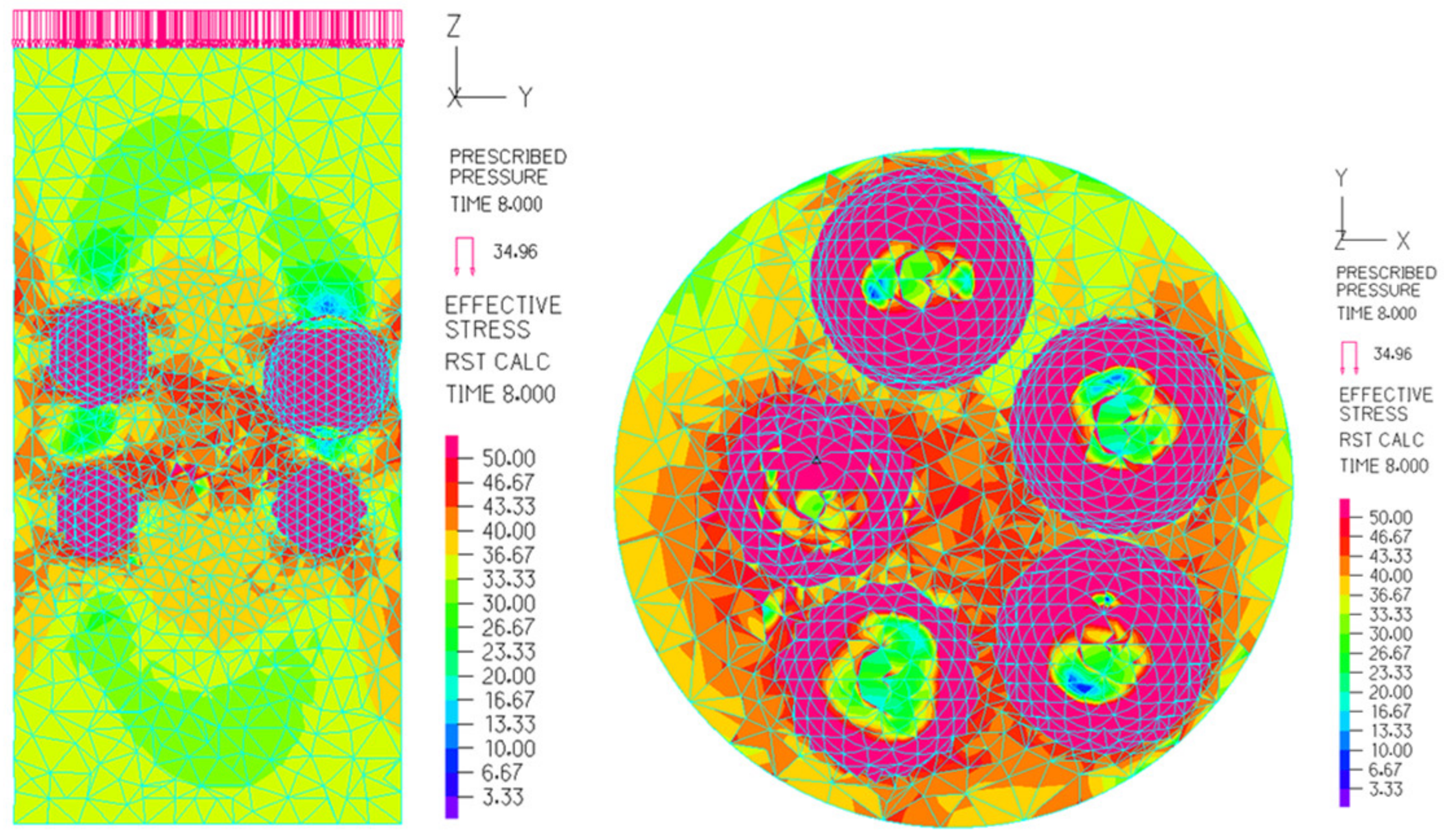
3.2. Finite Element Analysis

Figure 6 shows the internal stress distribution inside the BC. The deformation of the steel sphere triggered an uneven distribution of stresses inside the concrete. Stress concentration happens at the equatorial of the hollow body. The large stresses accompany vertical compression and oblique expansion. For the FEA, the hollow body model is connected to the concrete by common nodes, and the concrete stress is close to the hollow body. However, for the concrete experiments, the weak adhesion of steel spheres to the concrete is one of the dominating factors for the BC strength, so the analytical strength is generally higher than the experimental value. In addition, the increase in the number of steel spheres will aggravate the uneven distribution of stresses inside the concrete. A stress concentration is found between two neighboring steel spheres. If the spheres are close to the surface of the specimens, the peripheral concrete may be extruded.

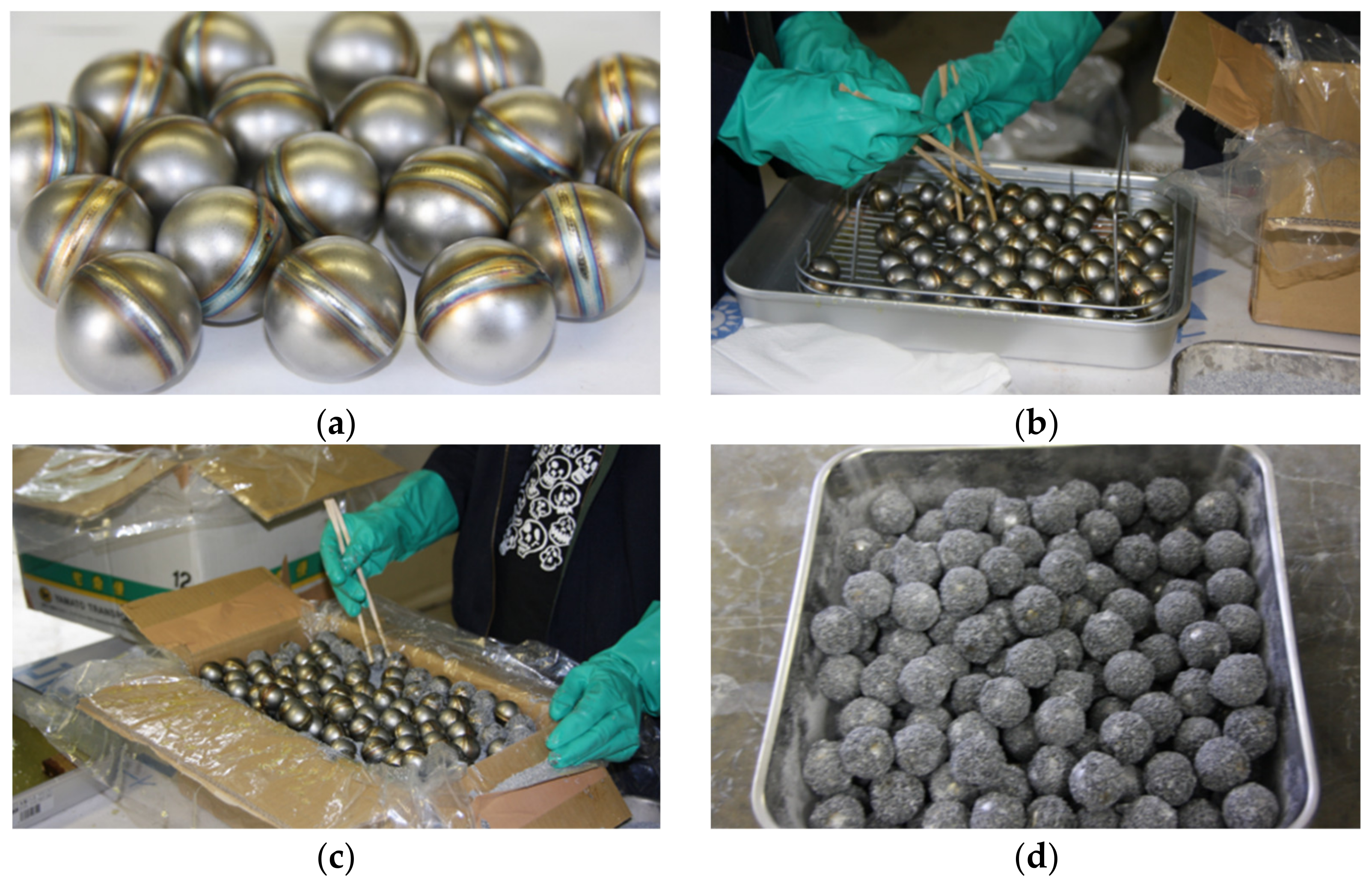
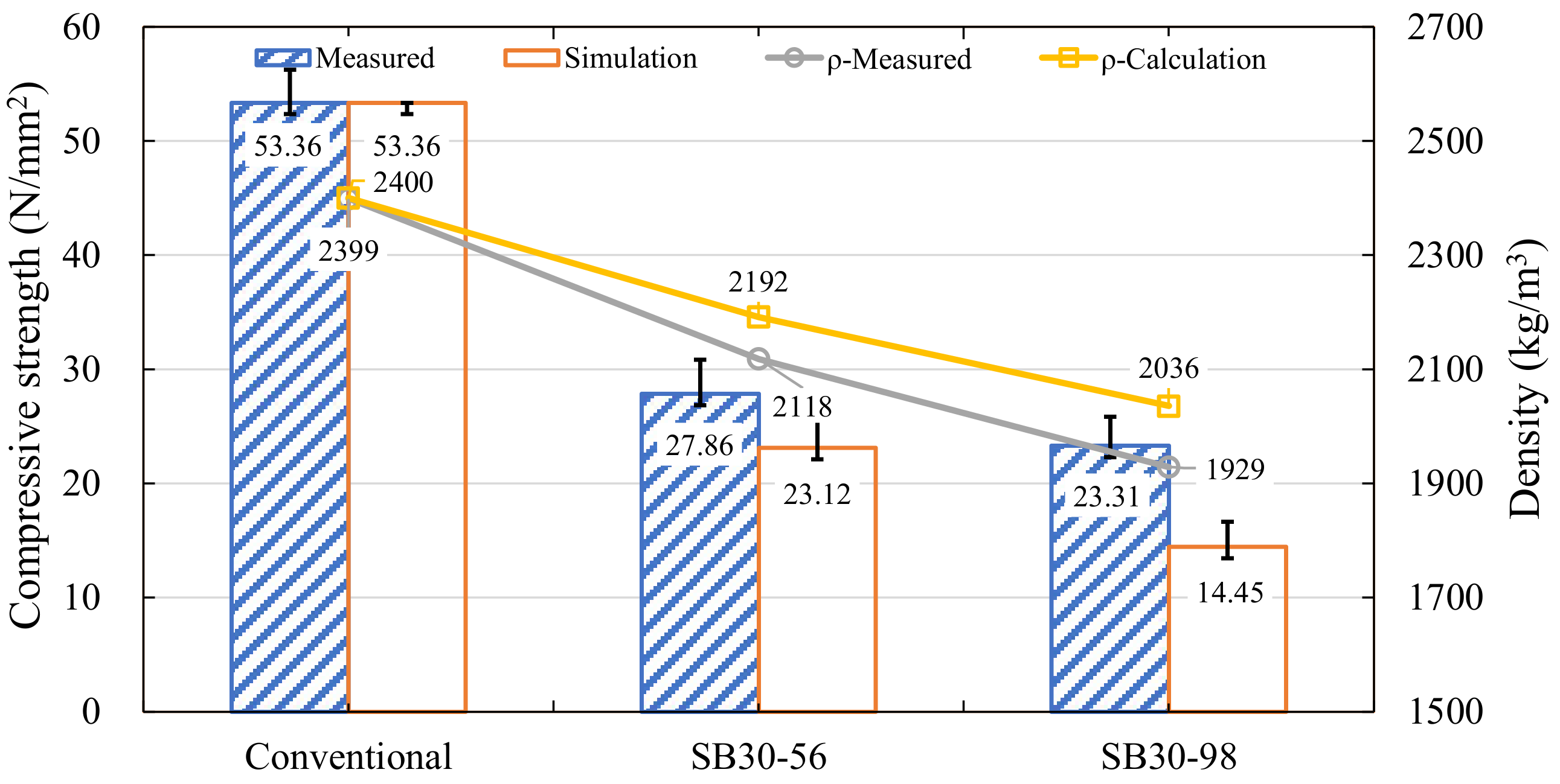
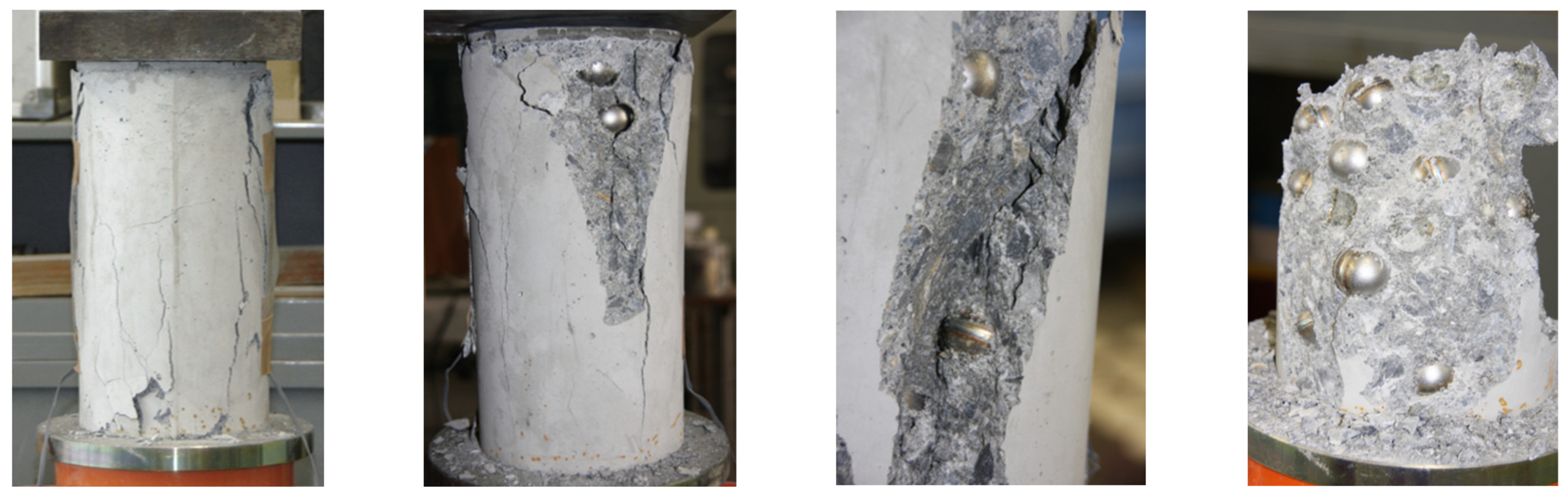
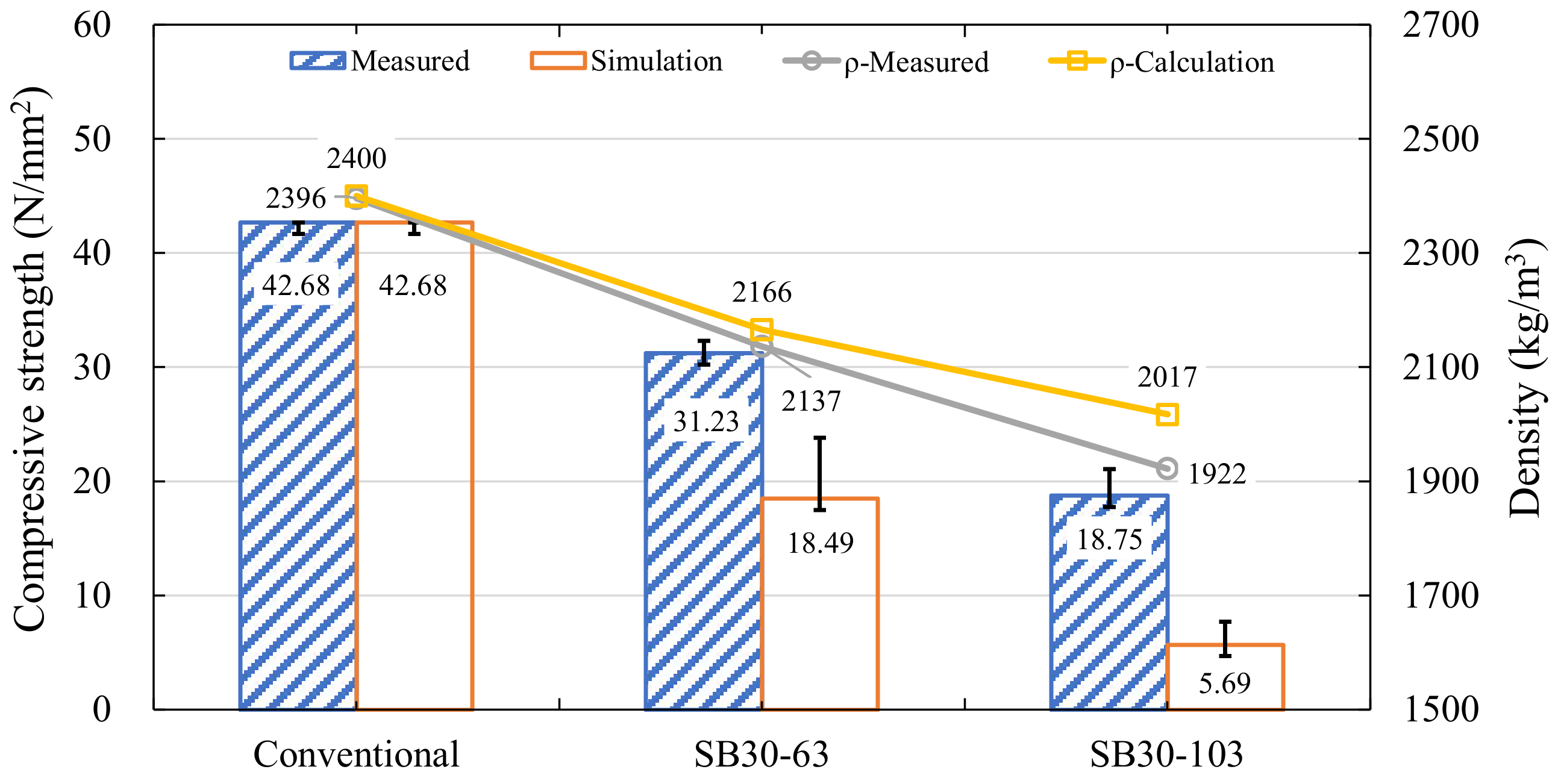
4. Bubble Concrete with Sand Bonded Stainless Steel Spheres

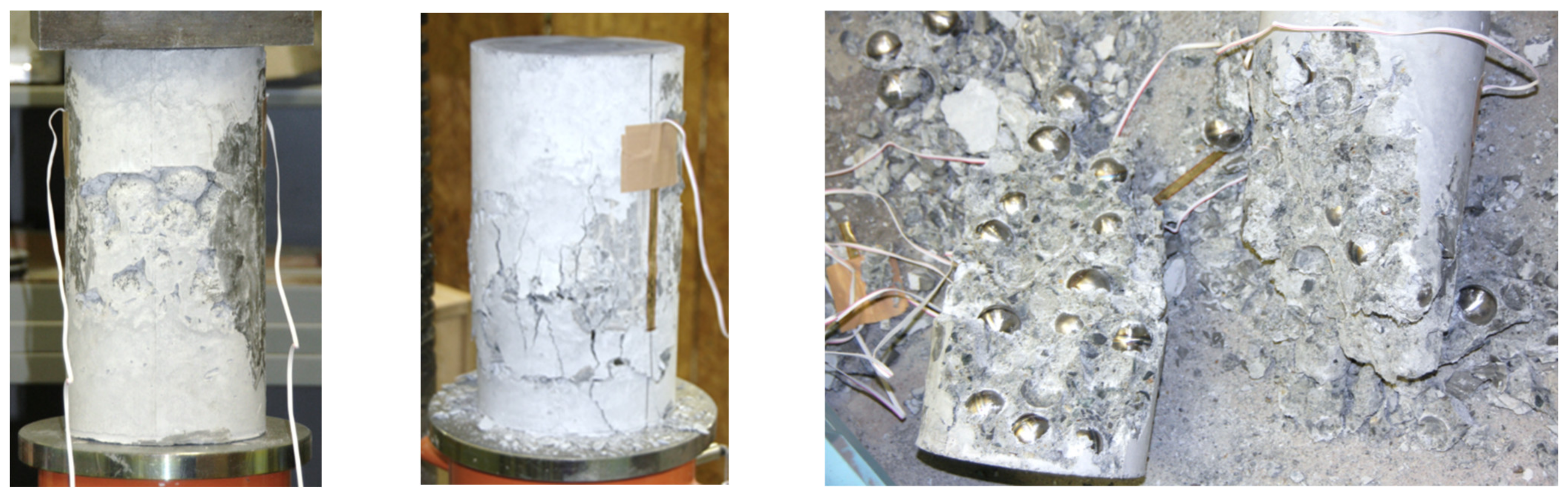
4.1. Concrete Compression Experiment

To improve the strength of the interface transition zone, epoxy resin was used to bond sand grains to the surface of the stainless steel sphere (Named as 2008 SB concrete), as shown in Figure 7. Experimental results of SS concrete have shown that excessive hollow body diameter exacerbates its separation. The hollow body was chosen as 30 mm in diameter, 0.8 mm in thickness, and the material was stainless steel of SUS-304 (JIS) with strength of 205 N / mm 2 . The sphere was formed from two welding hemispheres. The sand grain diameter was 0.59–1.18 mm, and the epoxy resin was Bond E set L with viscosity μ = 3000 cp (mPa−s). Due to the sand grains, the concrete mix ratio was adjusted based on the sphere numbers, as shown in Table 2. As the density of steel spheres was lower than that of coarse aggregates, the valid slump of BC cannot be measured. Three specimens of BC were made with 56 and 98 spheres, respectively, and three control specimens without spheres were made simultaneously.
Figure 8 and Figure 9 show that the strength and stiffness of 2008 SB concrete decrease with increasing the number of hollow bodies, but the strength improvement slightly compared to SS concrete. The average strength and density of control concrete were 53.36 N / mm 2 and 2399 kg/m3. The average strength of the specimens of SB30-56 and SB30-98 were 27.87 N / mm 2 and 23.31 N / mm 2 , respectively, while their average densities were 2.118 kg/m3 and 1.929 kg/m3, respectively. The strength was decreased to 43.7–52.2%, and the densities were decreased to 80.4–88.3% of the control specimens. The elastic modulus of 2008 SB concrete was measured as 2.18 ×   10 4   N / mm 2 and 1.66 ×   10 4   N / mm 2 , which was 40.7–53.4% compared to control concrete.
Figure 10 shows the failure picture of SB concrete. Vertical fine cracks were developed in the cylinder, and the width of the cracks gradually increased with the increasing load. Although the epoxy resin increased the adhesion between concrete and the hollow bodies, cracks inside the SB concrete were created between concrete and the hollow bodies, so separation of the hollow bodies was not eliminated. Reducing the diameter of the hollow body may cause small deformations on the hollow spheres. Consequently, the failure pattern of the BC appears as shear failure rather than splitting failure. It was found that the adhesion of epoxy resin between the sand grains and the spheres is lower than that between sand grains and surrounding concrete. In other words, low bonding strength to 2008 SB concrete is still one of the main reasons for damage occurring in BC.

4.2. Epoxy Resin with Stronger Adhesion

To further improve the interface strength and verify the hypothesis on the failure reasons of the SB concrete, a stronger epoxy resin was adopted (Named as 2009 SB concrete). The method and materials used were the same as 2008 SB concrete, while the epoxy resin was the type of Bond E250 with a viscosity of μ = 100,000 cp (mPa−s). The mix ratio of concrete paste was the same as that of 2008 SB concrete. The maximum coarse aggregate size was 15 mm, and the slump was 5 cm. Three concrete specimens incorporated 63 and 103 hollow bodies, and three specimens with conventional concrete were made for control concrete.
The strength of the 2009 SB concrete specimen was improved without noticeable changes in density, as shown in Figure 11. The average strength and density of conventional concrete were 41.76 N / mm 2 and 2396 kg/m3. It should be clarified that, as two control concretes were not well vibrated, the difference in compressive strength fluctuated drastically, so only the third concrete specimen (41.76 N / mm 2 ) was used in the comparison. The average strength and density of specimens SB30-63 and SB30-103 were 31.23 N / mm 2 and 18.75 N / mm 2 , 2137 kg/m3, and 1922 kg/m3, respectively. The strength was 43.9–73.2% for control concrete, while the density was 80.2–89.2% of control concrete. The elastic modulus of SB concrete was also improved to 2.27 ×   10 4   N / mm 2 and 1.54 ×   10 4   N / mm 2 , which decreased to 46.2–68.2% (see Figure 12). For G2-2 and G3-1 of Figure 12b, the non-curvilinear feature was found because of the deformation of the hollow body nearby the strain gauge, which leads to few valid values of strain that could be measured.
Figure 13 shows the failure picture of 2009 SB concrete. The concrete strength in this experiment was as expected, and the bonding interface strength was improved by means of viscous epoxy resin. Nevertheless, cracks were still generated in the interface transition zone. The multiple cracks inside the concrete gradually transformed into a top-down crack, which dislodged portions of the concrete. It means that the interface strength of epoxy resin is still lower than that of the cement and the aggregates. In addition, the increase in the number of hollow bodies caused lower fluidity of the concrete which prevented achieving better vibrations. In the process of vibrating, the stainless steel spheres floated up and converged together due to lower density. The decrease in cement paste content exacerbated the decrease in internal adhesion and was another reason for the decrease in concrete strength.

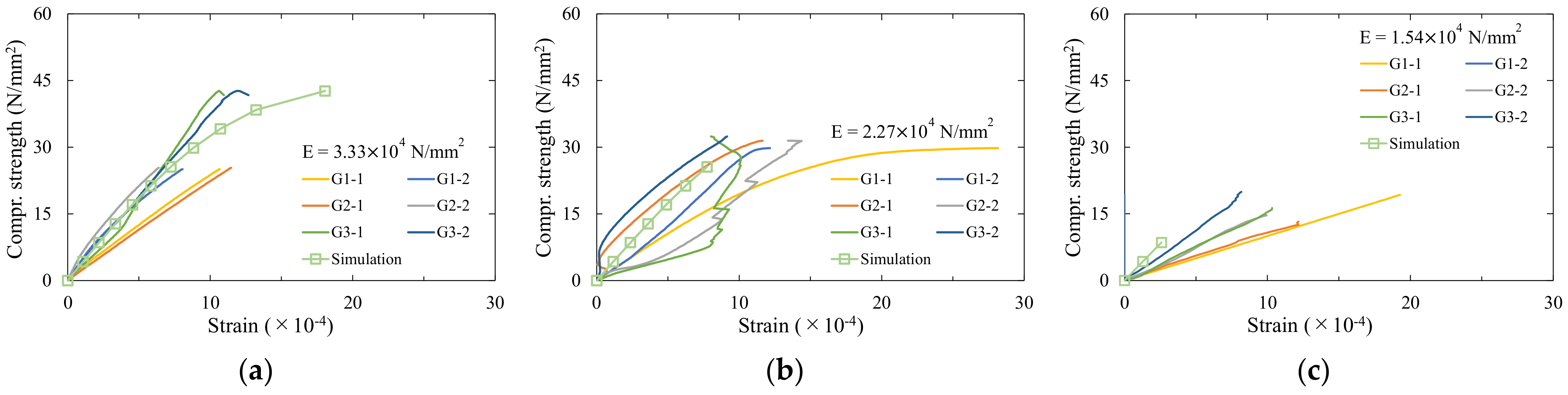
4.3. Finite Element Analysis

The stress distribution inside the SB concrete is shown in Figure 14. The reduction of the sphere diameter reduces the vertical and oblique deformation of the hollow body. However, the hollow bodies are randomly distributed in the concrete, and the stress concentration inside the concrete caused by the mutual extrusion of the spheres was not improved. Nevertheless, the concrete specimens did not reach the ultimate bearing strength, so the strength of the BC was lower than the strength of the concrete experiment.

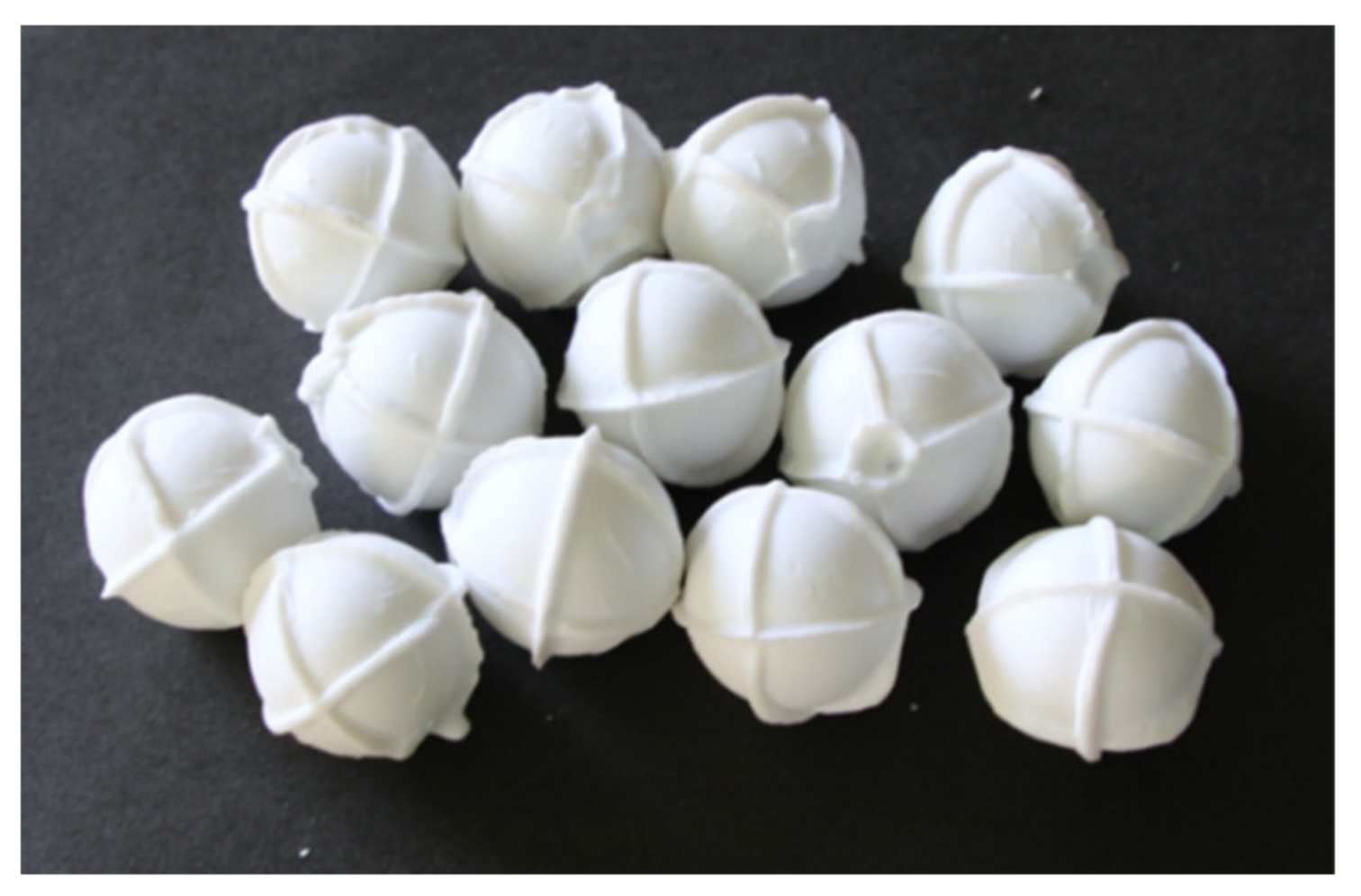
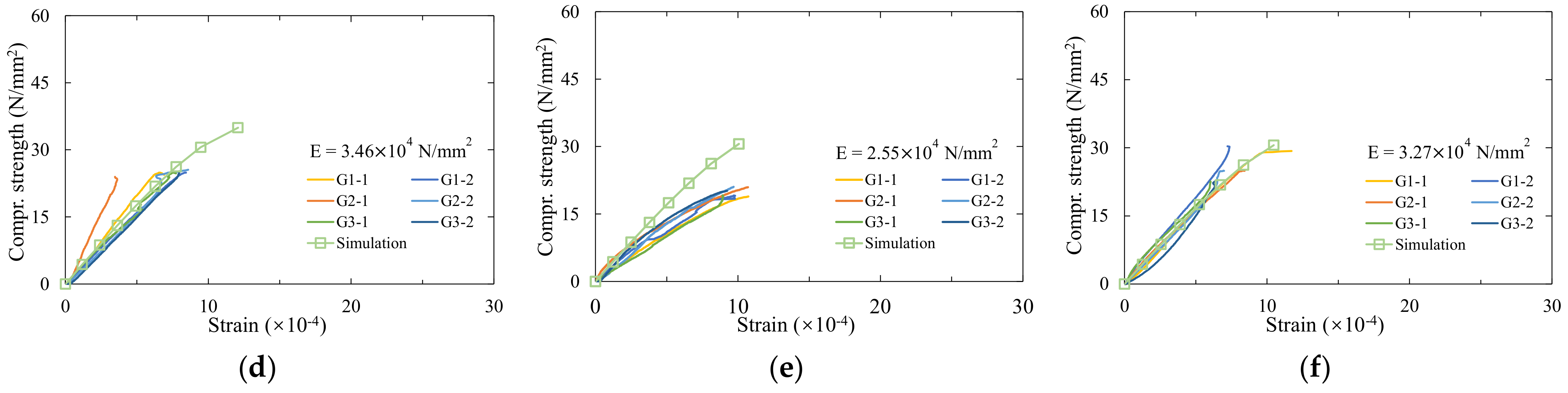
5. Bubble Concrete with Ceramic Spheres

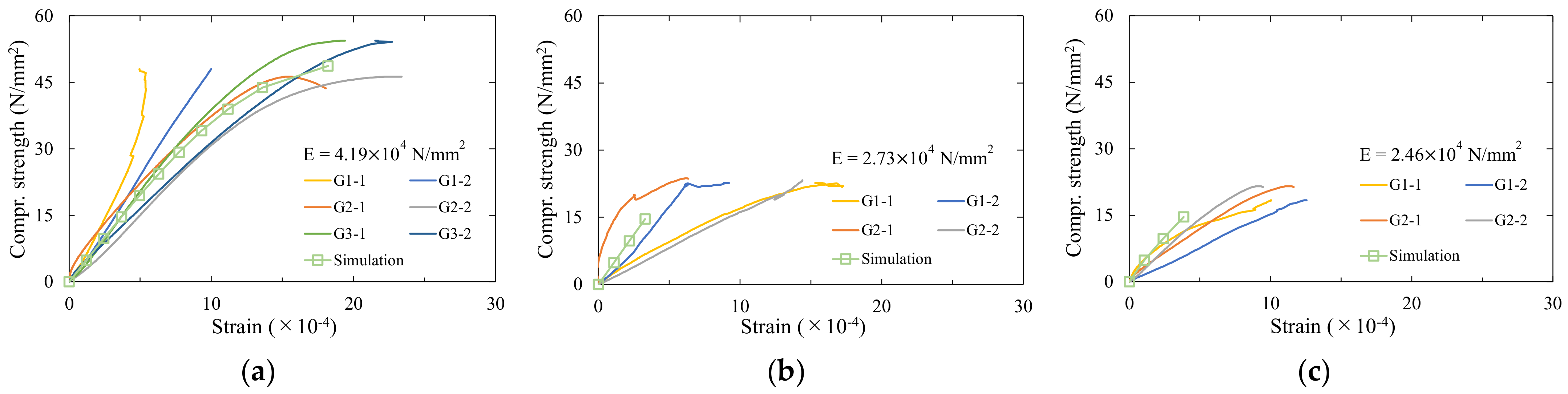
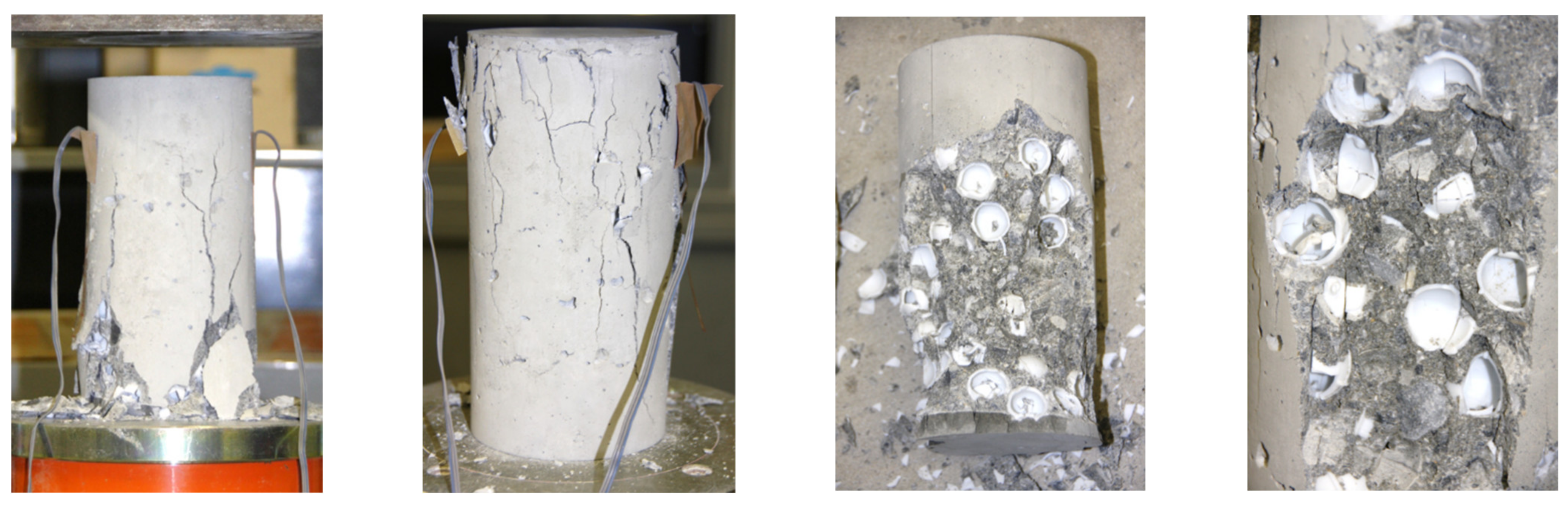
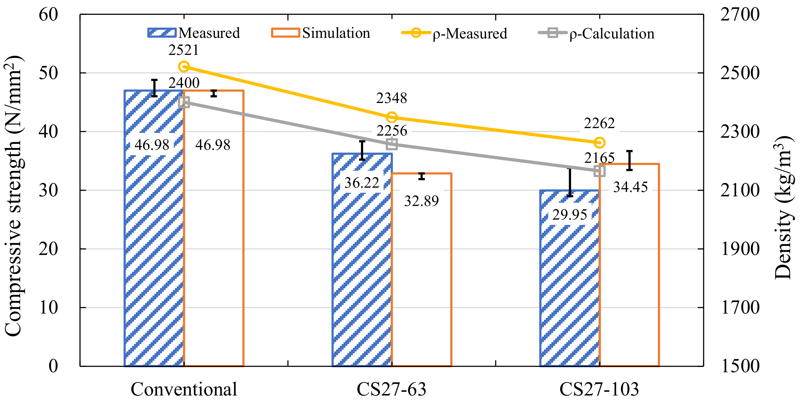
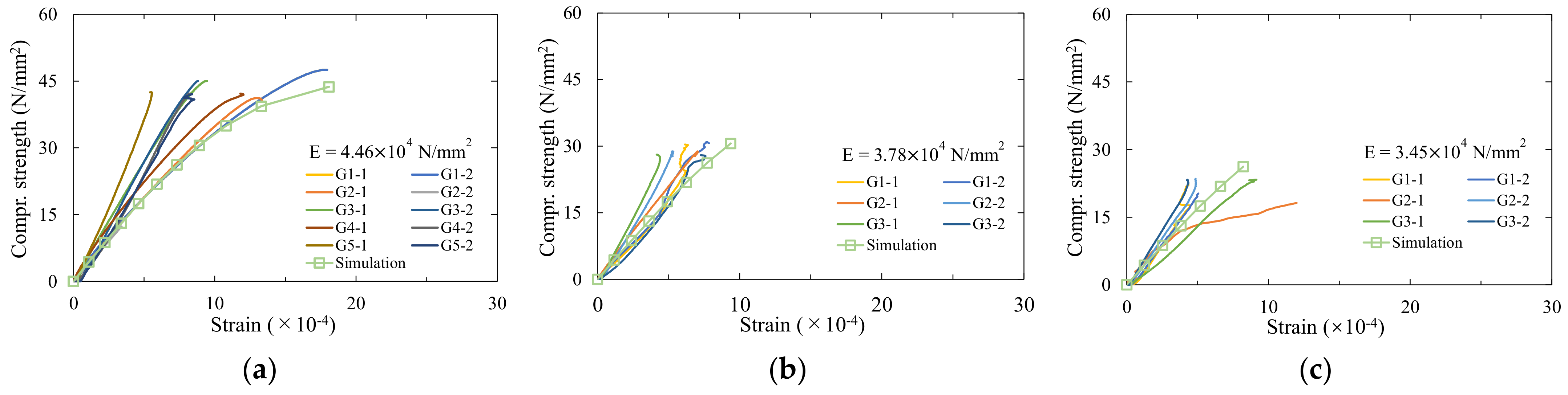
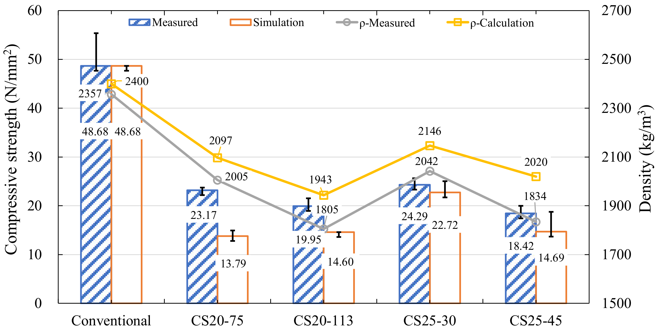
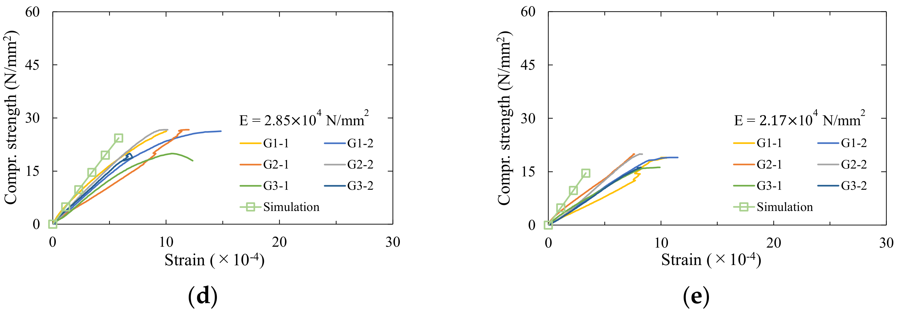
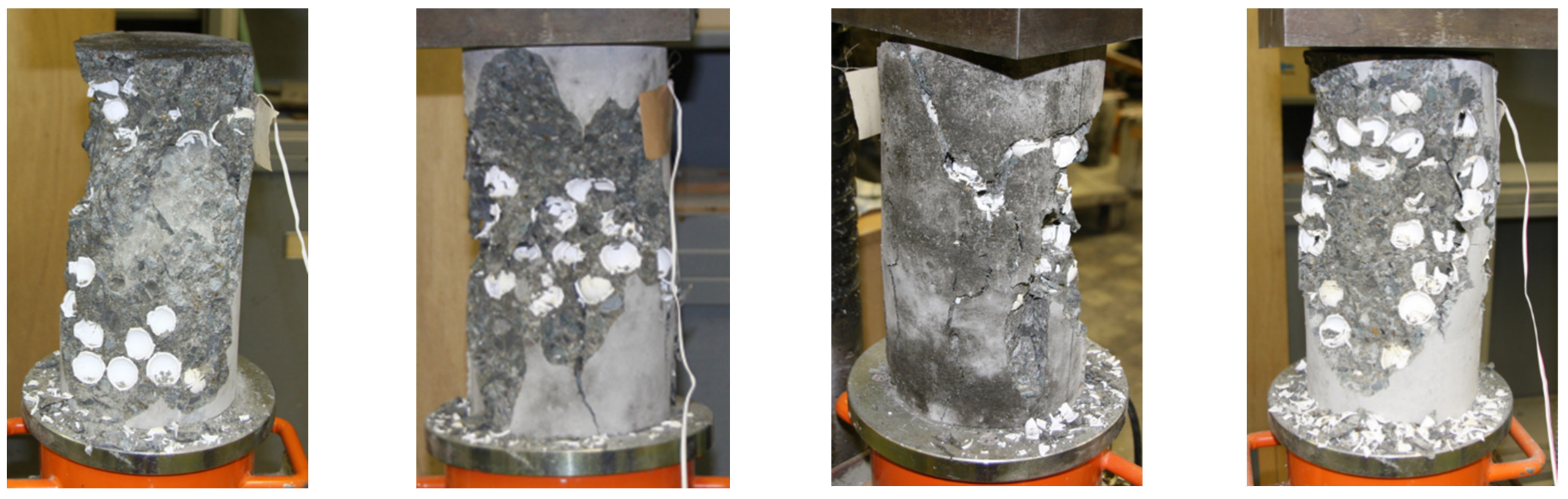
5.1. Concrete Compression Experiment

The reasons of smooth surface of the steel spheres and the difference between the elastic moduli cause the spheres to separate from the concrete after being subjected to stress. In contrast, the raw material of ceramics is clay, which is calcined at high temperatures [27]. Its surface is covered with many microscopic pores and exhibits strong adhesion to concrete. Moreover, the density of ceramic is lower than steel, which can further reduce the density of BC, which shows that it is a desirable hollow body material (Named as 2008 CS concrete). The ceramic spheres have been selected with a flexural strength of 95.1 N / mm 2 and a density of 2500 kg/m3 [28]. The mix ratio of concrete paste was the same as SS concrete. It should be noted that the diameter of the concrete specimen for this experiment is 100 mm, and the height is 200 mm.
The diameters of the ceramic sphere are 20 and 25 mm, while the thickness is 1.2–1.5 mm. In order to increase the compressive strength of the ceramic sphere, annular ribs with a thickness of 1 mm are added in the transverse and longitudinal directions to the ceramic sphere, as illustrated in Figure 15. The concrete specimens were divided into three groups according to the diameter and quantity of the hollow body. Three specimens were made in each group, and three conventional concrete specimens for comparison, as shown in Table 3.
The density and compressive strength of 2008 CS concrete are shown in Figure 16. The average of strength and density of the conventional concrete were 48.68 N/mm2 and 2357 kg/m3, respectively. The average strength and density of 2008 CS concrete were 18.42–24.29 N / mm 2 and 1805–2042 kg/m3, respectively. The strength decreased to 37.8–49.9%, and the density decreased to 77.8–86.6%. Compared with the SB concrete, the CS concrete performs lower strength but provides lighter densities. Raising the diameter of the hollow body was able to increase the strength of BC, but also indirectly increased its density. In addition, as shown in Figure 17, the elastic modulus of the BC was reduced to 2.85 ×   10 4   N / mm 2 , 2.17 ×   10 4   N / mm 2 , which was decreased to 51.8–68.0% of the control concrete. The elastic modulus of 2008 CS concrete was close to SB concrete but lower than SS concrete.
Figure 18 shows the failure picture of 2008 CS concrete. The ceramic spheres showed good adhesion, and no separation from the concrete was observed. However, as a brittle material different from steel, ceramic spheres were crushed, accompanying the failure of specimens. The deformation of the hollow body caused multiple cracks in the vertical direction of the concrete, accompanied by the dislodging of the concrete cover. The cracks on the ceramic sphere are mostly vertical cracks and transverse cracks concentrated at the sphere’s equator, and then the ceramic sphere cannot sustain the stress. In addition, unlike the shear failure of SB-2008 concrete, the ceramic spheres’ failure increased the concrete’s internal stress, and the concrete showed compression failure.

5.2. Higher-Strength Ceramic Spheres

The ceramics used in the 2008 experiments were poorer in strength, and even some of the ceramic spheres had been broken while producing concrete samples. Therefore, the ceramics with the component of 99.5% AI2O3, flexural strength of 390 N / mm 2 , and a density of 3980 kg/m3 have been applied (Named as 2009 CS concrete). The average diameter of the ceramic spheres is 27.71 mm, and the average thickness is 1.75 mm, with the same external annular ribs. The unit weight ratio of ingredients in concrete paste was water: cement: fine aggregate: coarse aggregate = 162: 360: 727: 1100, and the fine aggregate rate was 66.0%. Three concrete specimens with the number of hollow bodies of 63 and 103 were made, respectively, with three control concrete specimens.
The strength and stiffness of the concrete were obviously improved, as shown in Figure 19. The average strength and density of the conventional concrete were 46.98 N / mm 2 and 2521 kg/m3, while the average values for BC were 29.95–36.22 N / mm 2 and 2.262–2.348 kg/m3, respectively. The strength reduced to 29.95–36.22 N / mm 2 , and the density decreased to 89.6–93.0%. The stress–strain curves of 2009 CS concrete are shown in Figure 20. The elastic modulus of the 2009 CS concrete is 3.93–3.98 ×   10 4   N / mm 2 , which has been reduced to 97.5–98.8%. Compared with 2008 CS concrete, the elastic modulus of 2009 CS concrete was improved by over 30.8%.
Figure 21 shows the failure picture of the 2009 CS concrete. Compared to 2008 CS concrete, the ceramic spheres showed good adhesion to the concrete. Additionally, the number of longitudinal and transverse cracks initiated on the ceramic spheres was reduced, and the ceramic spheres mainly suffered a shear failure. The failure mode of concrete specimens also changed from compression failure to shear failure. Although the increased strength of the ceramic spheres improved the strength performance of the concrete, the hollow body was still unable to bear a large amount of stress. In addition, the more robust ceramic spheres increased the strength of the BC by 25.6–27.2%, which means that with the interface strength satisfied, enhancing the strength of the hollow body directly improved the strength of the BC.

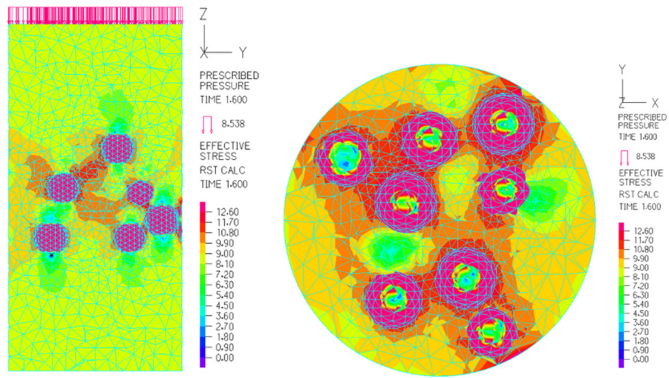
5.3. Finite Element Analysis
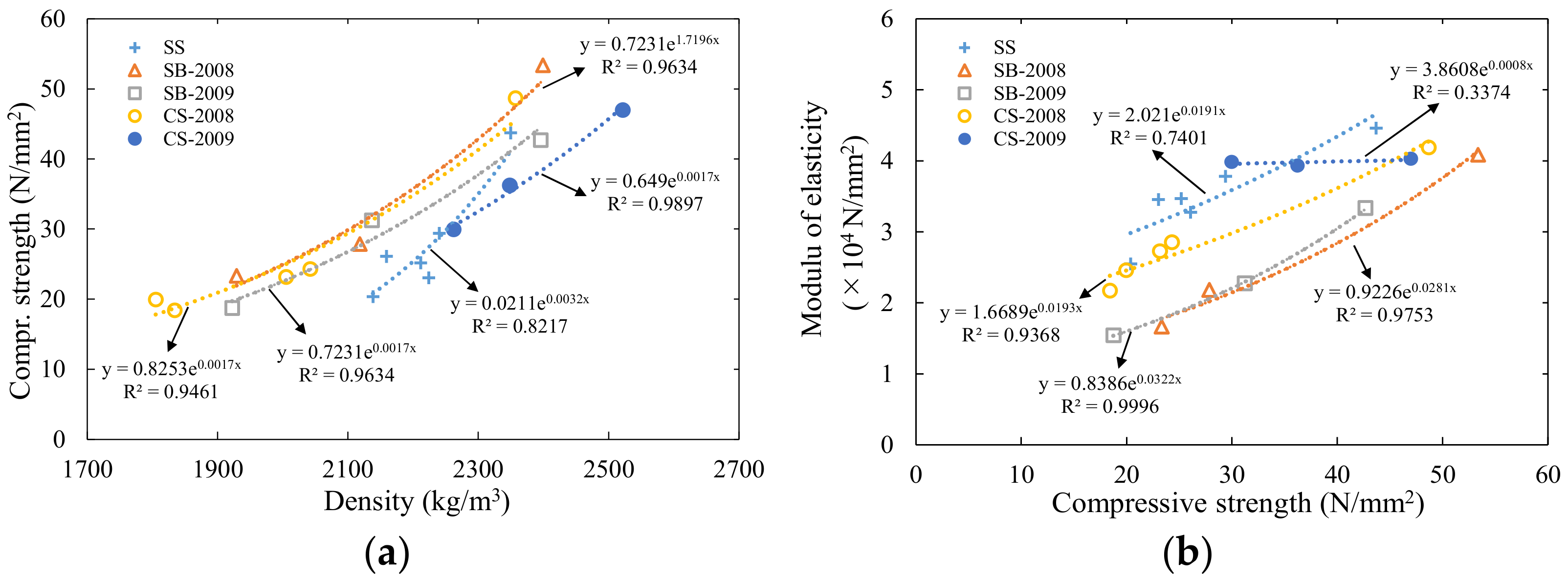
The stress distribution diagram of CS concrete is shown in Figure 22. The stress distribution characteristics inside the CS concrete are similar to SB concrete. However, due to the strength of the ceramic material having been improved, the hollow body was able to withstand greater loads. In other words, the ceramic hollow bodies could transfer stress continuously through their shell structure in concrete until overall failure. By comparing the failure mode in Figure 20 to Figure 9, it was found that if the issue of low interface strength has been overcome, the simulated stress–strain curves of BC are in good agreement with the experimental values.

6. Discussion

Density is one of the most critical factors controlling many physical properties of lightweight concrete [4,29], such as thermal conductivity, elastic modulus, splitting strength, flexural strength, compressive strength, et cetera. [6,9]. Most of these properties are positively correlated with concrete density, which means that as the density of concrete decreases, its physical and mechanical properties decrease. The strength density ratio (SDR) of the concrete specimen is shown in Figure 23. The SDR of BC is lower than that of conventional concrete. Although the strength of steel is much higher than that of the 2008 ceramic material, it still exhibits a similar SDR. With the help of epoxy resin, SB concrete slightly improves the SDR, which starts to deteriorate after the number of hollow bodies increases. The 2009 CS concrete provided the best SDR performance, meeting the JIS definition for Type 1 lightweight concrete [30], but also decreased with the number of hollow bodies increased.
Figure 24 shows the relationship between the density, compressive strength, and elastic modulus of BC. The relationship between BC’s density and compressive strength is consistent with other lightweight aggregate concretes. Among them, SS concrete exhibits the steepest exponential curve, meaning that as the density decreases, its strength decreases beyond the universal value. The similar exponential curve slopes of SB concrete and CS concrete prove that epoxy resin improves the adhesion between stainless steel spheres and concrete. However, due to the lower density of ceramics, the density of concrete is less than 1840 kg/m3, which meets the definition of structural lightweight concrete in ASTM C330/C330M–09.
The elastic modulus of the bubbled concrete shows a similar curve to the compressive strength. However, the elastic modulus of SS concrete and CS concrete is slightly higher than that of SB concrete, which indicates that the failure of SS and CS concrete is attributed to the deformation/destruction of the internal hollow body, so it exhibits “brittleness.” In contrast, the internal concrete with stainless steel spheres, because the epoxy resin provides a degree of adhesion that allows the concrete to withstand particular stress with minor deformation, exhibits little “plasticity”.

7. Conclusions

Because BC is a new type of material, this study focuses on its fundamental properties. This paper investigates the effect of hollow body material on the mechanical properties of BC. By comparing the BC with three types of hollow bodies with different materials, the strength of BC has increased to 19.95–23.17 N / mm 2 , and the density was maintained at 1805–2005 kg/m3, which satisfies the ASTM definition for structural concrete [10]. The main reasons for the reduction in strength of the three types of the BC can be summarized as the following four points:
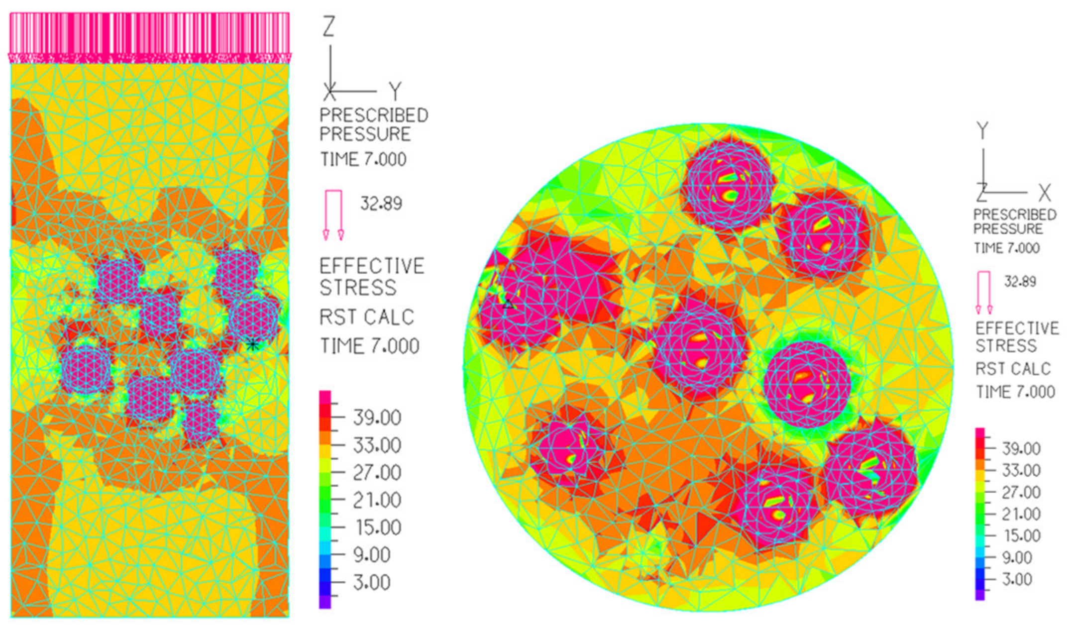
  • The different elastic moduli between the hollow body and concrete is the fundamental reason for the uneven stress distribution inside BC.
  • Insufficient adhesion between the hollow body and concrete gives low strength in the interfacial transition zone, and the hollow body is vulnerable to separation from the concrete.
  • The hollow body is subjected to enormous vertical stress. When the strength of the hollow body is insufficient, the hollow body will be compressed and damaged.
  • The hollow bodies are randomly distributed in the concrete. Some of the hollow bodies will converge together, and the volume of the cement slurry decreases, resulting in a cohesion decrease in the concrete. Moreover, the deformation of the hollow body will affect each other, causing the concrete to fail in advance.
In addition, specifically for these three types of BC, their characteristics as follows:
Hollow bodies made from steel and/or stainless steel have high capacity and ductility to bear stresses and absorb mechanical deformation. However, the high density of steel and stainless steel restricts the potential to reduce the weight of the BC. Moreover, the smooth surface shows a low adhesion to concrete, so the hollow body cannot continuously transfer stress. Epoxy resin can increase the adhesion between hollow bodies and concrete, but the strength of the interface transition zone is still lower than that of concrete. The ceramic spheres with lighter density and better adhesion provide a better performance in reducing the specific gravity of concrete and ensuring the strength of concrete. However, brittle materials are prone to brittle failure when making concrete specimens and conducting concrete compression experiments.
Furthermore, some of the ceramic spheres floated and lumped together during casting and vibrating concrete for their light weight (low density). Some lumped groups of spheres restricted concrete paste to be filled into the spaces between spheres, which leads to premature breaking of the ceramics. Among the three hollow body materials, the performance of the BC using ceramic spheres is the most ideal one, while the high strength of the hollow body is required.

Author Contributions

Conceptualization, P.-S.C.; methodology, P.-S.C.; formal analysis, X.Y.; investigation, X.Y.; resources, P.-S.C.; data curation, P.-S.C., and X.Y.; writing—original draft preparation, X.Y.; writing—review and editing, X.Y., P.-S.C., B.L., B.S.M. and J.J.; visualization, X.Y.; supervision, P.-S.C. and B.S.M.; project administration, X.Y., P.-S.C. All authors have read and agreed to the published version of the manuscript.

Funding

This research was funded by The Special Research Supporting of Hachinohe Institute of Technology 2013, grant number: Tokutei-1 and Joint Research Program by, and between Kyushu Institute of Technology and Universiti Teknologi Petronas (2020–2022), and The APC was funded by Joint Research Program by and between Kyushu Institute of Technology and Universiti Teknologi Petronas.

Institutional Review Board Statement

Not applicable.

Informed Consent Statement

Not applicable.

Data Availability Statement

The corresponding author will provide the datasets created and analyzed during this study upon reasonable request.

Acknowledgments

We would like to thank the Architectural Design Research Laboratory graduates of Hachinohe Institute of Technology for their data support for this thesis.

Conflicts of Interest

The authors declare no conflict of interest.

References

  1. Smadi, M.; Migdady, E. Properties of High Strength Tuff Lightweight Aggregate Concrete. Cem. Concr. Compos. 1991, 13, 129–135. [Google Scholar] [CrossRef]
  2. Ünal, O.; Uygunoğlu, T.; Yildiz, A. Investigation of Properties of Low-Strength Lightweight Concrete for Thermal Insulation. Build. Environ. 2007, 42, 584–590. [Google Scholar] [CrossRef]
  3. Posi, P.; Lertnimoolchai, S.; Sata, V.; Chindaprasirt, P. Pressed Lightweight Concrete Containing Calcined Diatomite Aggregate. Constr. Build. Mater. 2013, 47, 896–901. [Google Scholar] [CrossRef]
  4. Kan, A.; Demirboğa, R. A Novel Material for Lightweight Concrete Production. Cem. Concr. Compos. 2009, 31, 489–495. [Google Scholar] [CrossRef]
  5. Swamy, R.N.; Lambert, G.H. Mix Design and Properties of Concrete Made from PFA Coarse Aggregates and Sand. Int. J. Cem. Compos. Lightweight Concr. 1983, 5, 263–275. [Google Scholar] [CrossRef]
  6. Bogas, J.A.; de Brito, J.; Figueiredo, J.M. Mechanical Characterization of Concrete Produced with Recycled Lightweight Expanded Clay Aggregate Concrete. J. Clean. Prod. 2015, 89, 187–195. [Google Scholar] [CrossRef]
  7. Rashad, A.M. Lightweight Expanded Clay Aggregate As A Building Material—An Overview. Constr. Build. Mater. 2018, 170, 757–775. [Google Scholar] [CrossRef]
  8. Lotfy, A.; Hossain, K.M.A.; Lachemi, M. Lightweight Self-Consolidating Concrete with Expanded Shale Aggregates: Modelling and Optimization. Int. J. Concr. Struct. Mater. 2015, 9, 185–206. [Google Scholar] [CrossRef]
  9. Lo, T.Y.; Tang, W.C.; Cui, H.Z. The Effects of Aggregate Properties on Lightweight Concrete. Build. Environ. 2007, 42, 3025–3029. [Google Scholar] [CrossRef]
  10. Mehta, P.K.; Monteiro, P.J.M. Concrete: Microstructure, Properties, and Materials, 2nd ed.; Prentice-Hall Inc.: Englewood Cliffs, NJ, USA, 1986. [Google Scholar]
  11. Hasan, M.; Saidi, T.; Afifuddin, M. Mechanical Properties and Absorption of Lightweight Concrete Using Lightweight Aggregate from Diatomaceous Earth. Constr. Build. Mater. 2021, 277, 122324. [Google Scholar] [CrossRef]
  12. ASTM C330/C330M-09; Specification for Lightweight Aggregates for Structural Concrete. ASTM International: West Conshohocken, PA, USA, 2009.
  13. Ramamurthy, K.; Kunhanandan Nambiar, E.K.; Indu Siva Ranjani, G. A Classification of Studies on Properties of Foam Concrete. Cem. Concr. Compos. 2009, 31, 388–396. [Google Scholar] [CrossRef]
  14. Newman, J.; Choo, B.S. Advanced Concrete Technology, 1st ed.; Butterworth-Heinemann: Oxford, UK, 2003. [Google Scholar]
  15. Bremner, T.W.; Newman, J.B. Microstructure of Low Density Concrete Aggregate. In Proceedings of the 9th Congress of FIP, Stockholm, Sweden, 6–10 June 1992; FIP: Slough, UK, 1992; Volume 417. [Google Scholar]
  16. Galilei, G.; Crew, H. Dialogues Concerning Two New Sciences; Crew, H., de Salvio, A., Eds.; Macmillan Company: London, UK, 1638. [Google Scholar]
  17. Chen, P. Bubble Concrete. Japan Patent Office JP2008308395, 25 December 2008. Available online: https://www.j-platpat.inpit.go.jp/p0200 (accessed on 5 April 2022).
  18. Chen, P. A Study Report on Light Weight Concrete Mixed With High Strength Hollow Bubbles. In Proceedings of the AIJ Tohoku Chapter Architectural Research Meeting (Kouzoukei), Tokyo, Japan, 2008; Architectural Institute of Japan: Tokyo, Japan, 2008; No. 71; pp. 57–62. [Google Scholar]
  19. Schnellenbach-Held, M.; Pfeffer, K. Punching Behavior of Biaxial Hollow Slabs. Cem. Concr. Compos. 2002, 24, 551–556. [Google Scholar] [CrossRef]
  20. Chung, J.H.; Choi, H.K.; Lee, S.C.; Choi, C.S. Shear Capacity of Biaxial Hollow Slab with Donut Type Hollow Sphere. Procedia Eng. 2011, 14, 2219–2222. [Google Scholar] [CrossRef] [Green Version]
  21. Churakov, A. Biaxial Hollow Slab with Innovative Types of Voids. Constr. Unique Build. Struct. 2014, 6, 70–88. [Google Scholar]
  22. Chen, P.-S.; Tsukinaga, Y. Basic Research on the Development of Light Weight Concrete Mixed With Hollow Spheres. J. Soc. Mater. Sci. Jpn. 2015, 64, 711–717. [Google Scholar] [CrossRef] [Green Version]
  23. Yan, X.; Chen, P.-S.; Al-Fakih, A.; Liu, B.; Mohammed, B.S.; Jin, J. Experiments and Mechanical Simulation on Bubble Concrete: Studies on the Effects of Shape and Position of Hollow Bodies Mixed in Concrete. Crystals 2021, 11, 858. [Google Scholar] [CrossRef]
  24. Yan, X.; Chen, P.-S. Effect of Hollow Body Shape on the Internal Stress Distribution of Bubble Concrete. In Proceedings of the 7th International Conference on Architecture, Materials and Construction (ICAMC 2021), Lisbon, Portugal, 27–29 October 2021; Mendonça, P., Cortiços, N.D., Eds.; Springer International Publishing: Cham, Switzerland, 2022; pp. 223–229. [Google Scholar]
  25. Yan, X.; Chen, P.-S.; Mohammed, B.S.; Liu, B. Effect of Hollow Bodies on the Strength and Density of Bubble Concrete. In Proceedings of the AWAM International Conference in Civil Engineering (AICCE’22), Penang, Malaysia, 15–17 February 2022. Lecture Notes in Civil Engineering: Penang, Malaysia, 2022. [Google Scholar]
  26. Japanese Industrial Standard (JIS). JIS A 1108: 2018, Method of Test for Compressive Strength of Concrete. Available online: https://webdesk.jsa.or.jp/preview/pre_jis_a_01108_000_000_2018_j_ed10_ch.pdf (accessed on 4 April 2022).
  27. Munz, D.; Fett, T. Ceramics: Mechanical Properties, Failure Behaviour, Materials Selection; Springer Series in Materials Science; Springer: Berlin/Heidelberg, Germany; New York, NY, USA, 1999; ISBN 978-3-540-65376-9. [Google Scholar]
  28. Japanese Industrial Standard (JIS). JIS A 1106: 2018, Method of Test for Flexural Strength of Concrete. Available online: http://www.kikakurui.com/a1/A1106-2018-01.html (accessed on 4 May 2022).
  29. Kan, A.; Demirbo, R. Effect of Cement and EPS Beads Ratios on Compressive Strength and Density of Lightweight Concrete. Indian J. Eng. Mater. Sci. 2007, 14, 158–162. [Google Scholar]
  30. Chen, P.-S. Architectural Structure Design Textbook, 1st ed.; Morikita Publishing Company, Ltd.: Tokyo, Japan, 2015; p. 21. [Google Scholar]
Figure 1. Schematic diagram of BC.
Crystals 12 00708 g001
Figure 2. Analytical model and stress–strain curve for analysis. (a) Concrete specimen used for SS50–20. (b) Steel sphere (SS50–20). (c) Stainless steel sphere (SB30–56). (d) Ceramic sphere (CS27–63).
Crystals 12 00708 g002
Figure 3. The density and compressive strength of SS concrete.
Crystals 12 00708 g003
Figure 4. The stress–strain curve of SS concrete. (a) Conventional concrete. (b) SS50–20. (c) SS50–40. (d) SS60–8. (e) SS60–12. (f) SS60–16.
Crystals 12 00708 g004aCrystals 12 00708 g004b
Figure 5. The failure picture of SS concrete.
Crystals 12 00708 g005
Figure 6. The internal stress diagram of SS concrete (SS50–40).
Crystals 12 00708 g006
Figure 7. Coating stainless steel spheres using sand grains. (a) Stainless steel spheres. (b) Coating with epoxy resin. (c) Coating with sand grains. (d) Sand-coated stainless steel spheres.
Crystals 12 00708 g007
Figure 8. The density and compressive strength of SB concrete.
Crystals 12 00708 g008
Figure 9. The stress–strain curve of SB concrete. (a) Conventional concrete. (b) SB30–56. (c) SB30–98.
Crystals 12 00708 g009
Figure 10. The failure picture of SB concrete.
Crystals 12 00708 g010
Figure 11. The density and compressive strength of 2009 SB concrete.
Crystals 12 00708 g011
Figure 12. The stress–strain curve of 2009 SB concrete. (a) Conventional concrete. (b) SB30–63. (c) SB30–103.
Crystals 12 00708 g012
Figure 13. The failure picture of 2009 SB concrete.
Crystals 12 00708 g013
Figure 14. The internal stress diagram of SB concrete (SB30–56).
Crystals 12 00708 g014
Figure 15. Ceramic spheres.
Crystals 12 00708 g015
Figure 16. The density and compressive strength of 2008 CS concrete.
Crystals 12 00708 g016
Figure 17. The stress–strain curve of 2008 CS concrete. (a) Conventional concrete. (b) CS20–75. (c) CS20–113. (d) CS25–30. (e) CS25–45.
Crystals 12 00708 g017aCrystals 12 00708 g017b
Figure 18. The failure picture of 2008 CS concrete.
Crystals 12 00708 g018
Figure 19. The density and compressive strength of 2009 CS concrete.
Crystals 12 00708 g019
Figure 20. The stress–strain curve of 2009 CS concrete. (a) Conventional concrete. (b) CS27–63. (c) CS27–103.
Crystals 12 00708 g020
Figure 21. The failure picture of 2009 CS concrete.
Crystals 12 00708 g021
Figure 22. The internal stress diagram of CS concrete (CS27–103).
Crystals 12 00708 g022
Figure 23. Strength density ratio of concrete specimens.
Crystals 12 00708 g023
Figure 24. The relationship between the density, compressive strength, and elastic modulus.
Crystals 12 00708 g024
Table 1. The sphere diameters and the number of spheres.
TypeDiameter (mm)Thickness (mm)Sphere NumberSpecimen Number
SS50–2048.62.3183
SS50–4048.62.3273
SS60–860.52.383
SS60–1260.52.3123
SS60–1660.52.3163
Table 2. Concrete mix ratio and the amount of steel spheres mixed.
IngredientsDensity
(g/cm3)
Conventional ConcreteSB30-56SB30-98
Weight
(g)
Volume (cm3)Weight
(g)
Volume (cm3)Weight
(g)
Volume
(cm3)
Steel sphere1.00002343.002332.634132.204113.92
Water1.002526.502526.502567.812567.812599.362599.36
Cement3.165653.301788.525745.741840.095816.341840.09
Fine aggregate2.6911,380.004230.9411,566.094352.9611,708.194352.96
Coarse aggregate2.6917,810.006620.5011,534.94287.876743.042506.59
AE/Air-17.50715.6917.81728.4518.03737.40
Sum-37,387.3015,882.1633,775.3816,034.6531,017.1616,150.32
Unit concrete specimen-12,462.435294.0511,258.465344.8810,339.055383.44
Table 3. The sphere diameters and the number of spheres mixed.
TypeDiameter (mm)Thickness (mm)Sphere NumberSpecimen Number
CS20-7520.061.2752
CS20-11320.061.21132
CS25-3026.441.2303
CS25-4526.441.2453
Publisher’s Note: MDPI stays neutral with regard to jurisdictional claims in published maps and institutional affiliations.

