
Crystal Breakage Due to Combined Normal and Shear Loading


Abstract
:1. Introduction
2. Theory
Comminution
- 1.
- cracking;
- 2.
- crack initiation;
- 3.
- crack propagation.
3. Materials and Methods
3.1. Crystallization
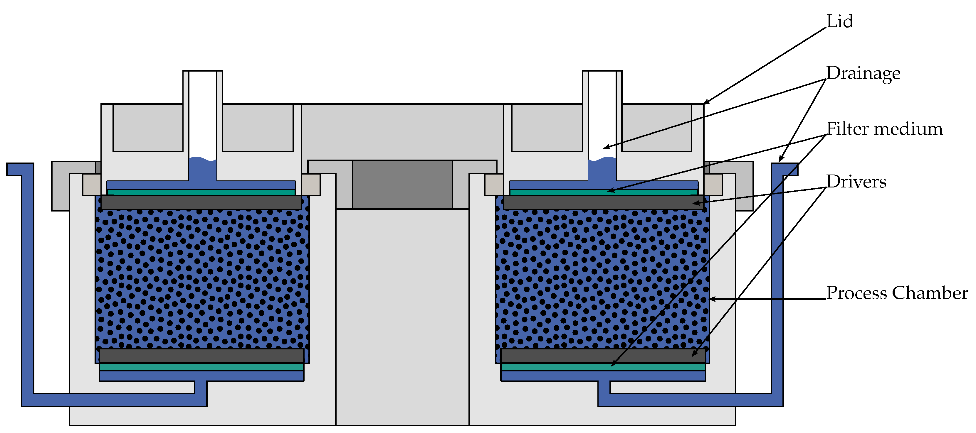
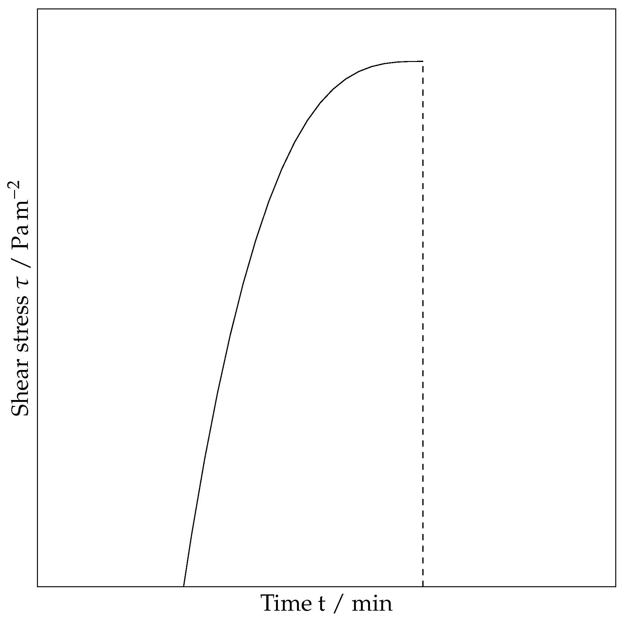
3.2. Modified Shear Cell and Ring Shear Tester
- 1.
- sample preparation;
- 2.
- shear cell assembly;
- 3.
- shear cell preparation;
- 4.
- shear test.
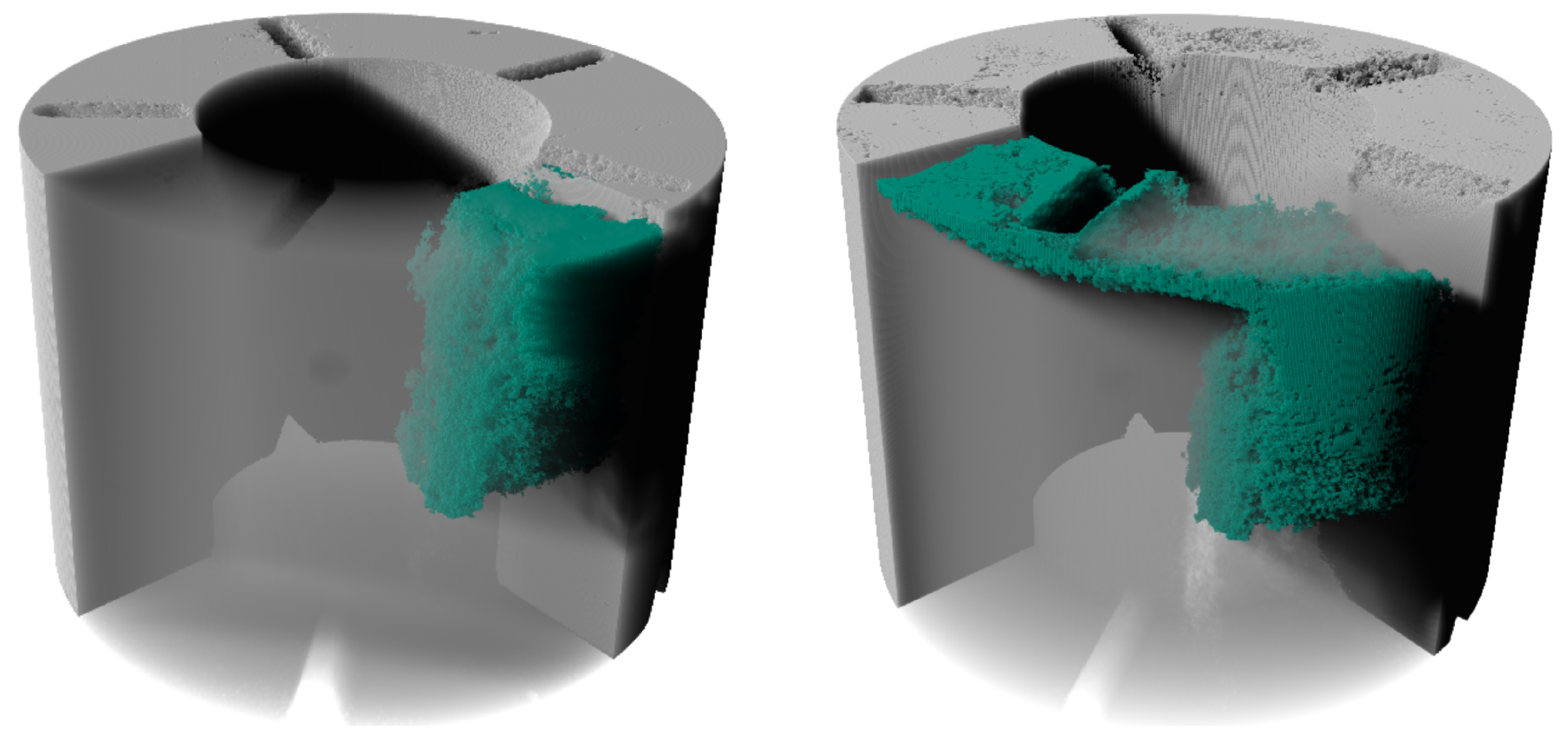
3.3. Micro Computed Tomography Analytic
4. Results and Discussion
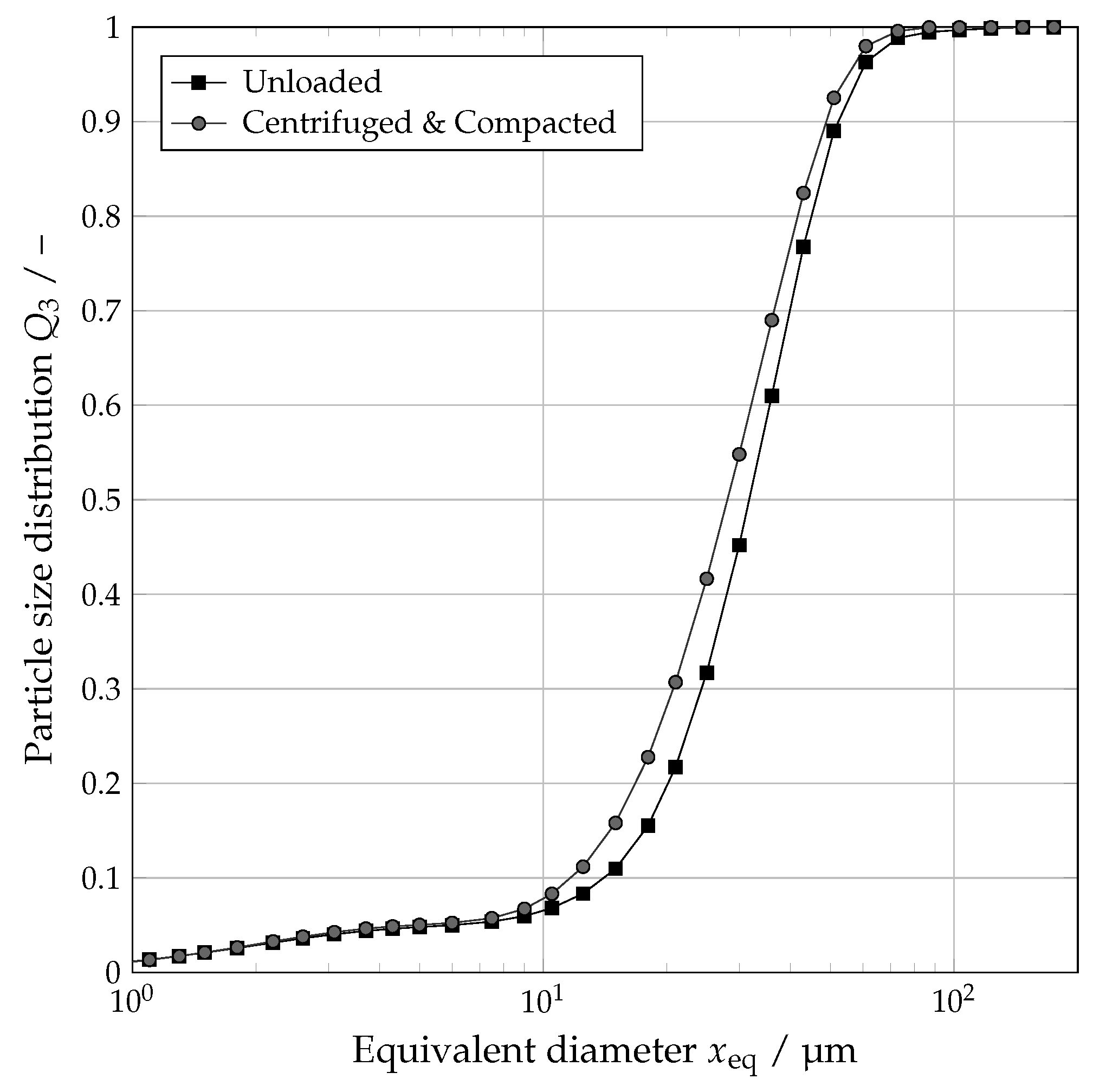
4.1. Influence of Centrifugation and Compaction
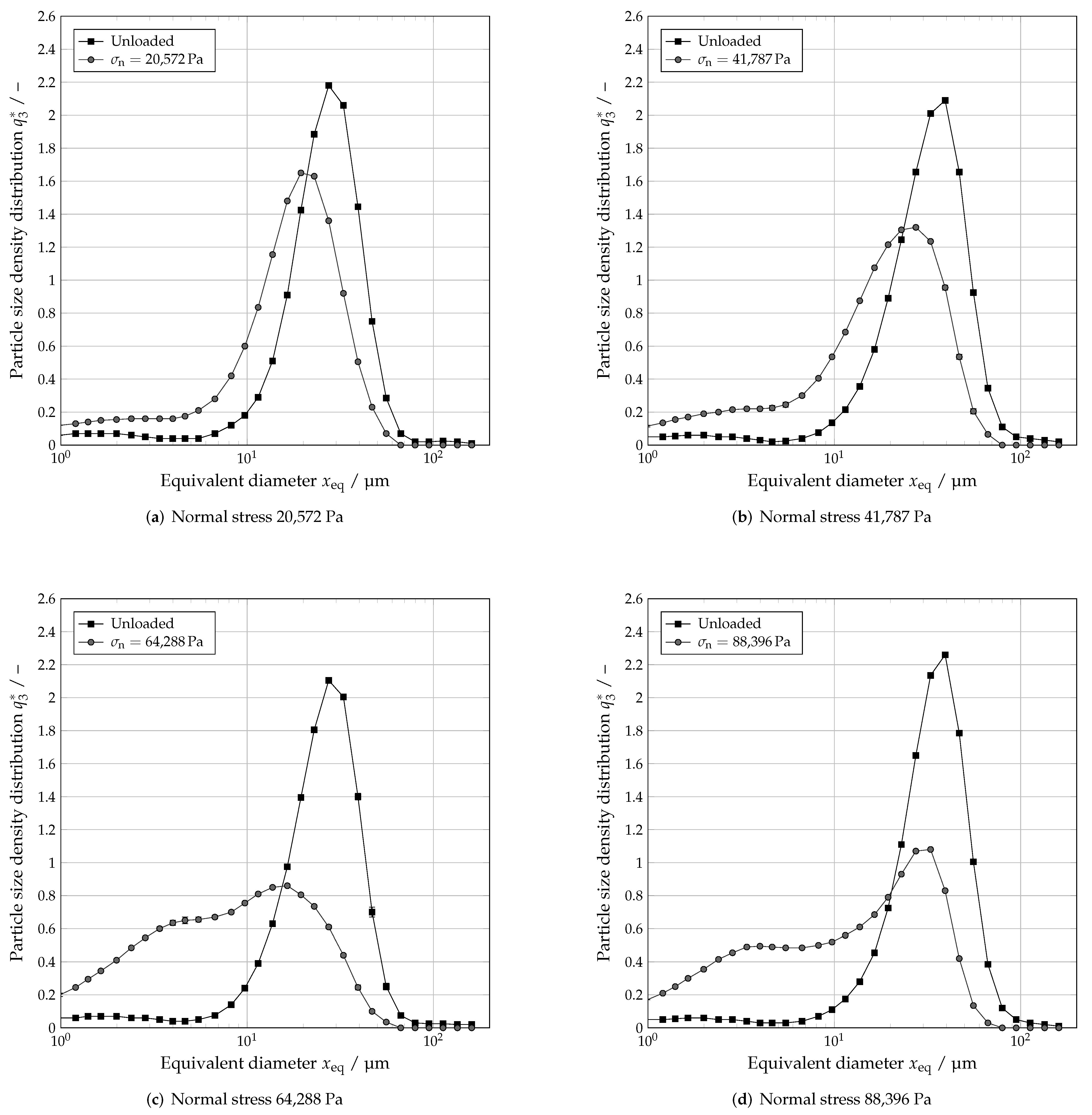
4.2. Influence of Normal Stress
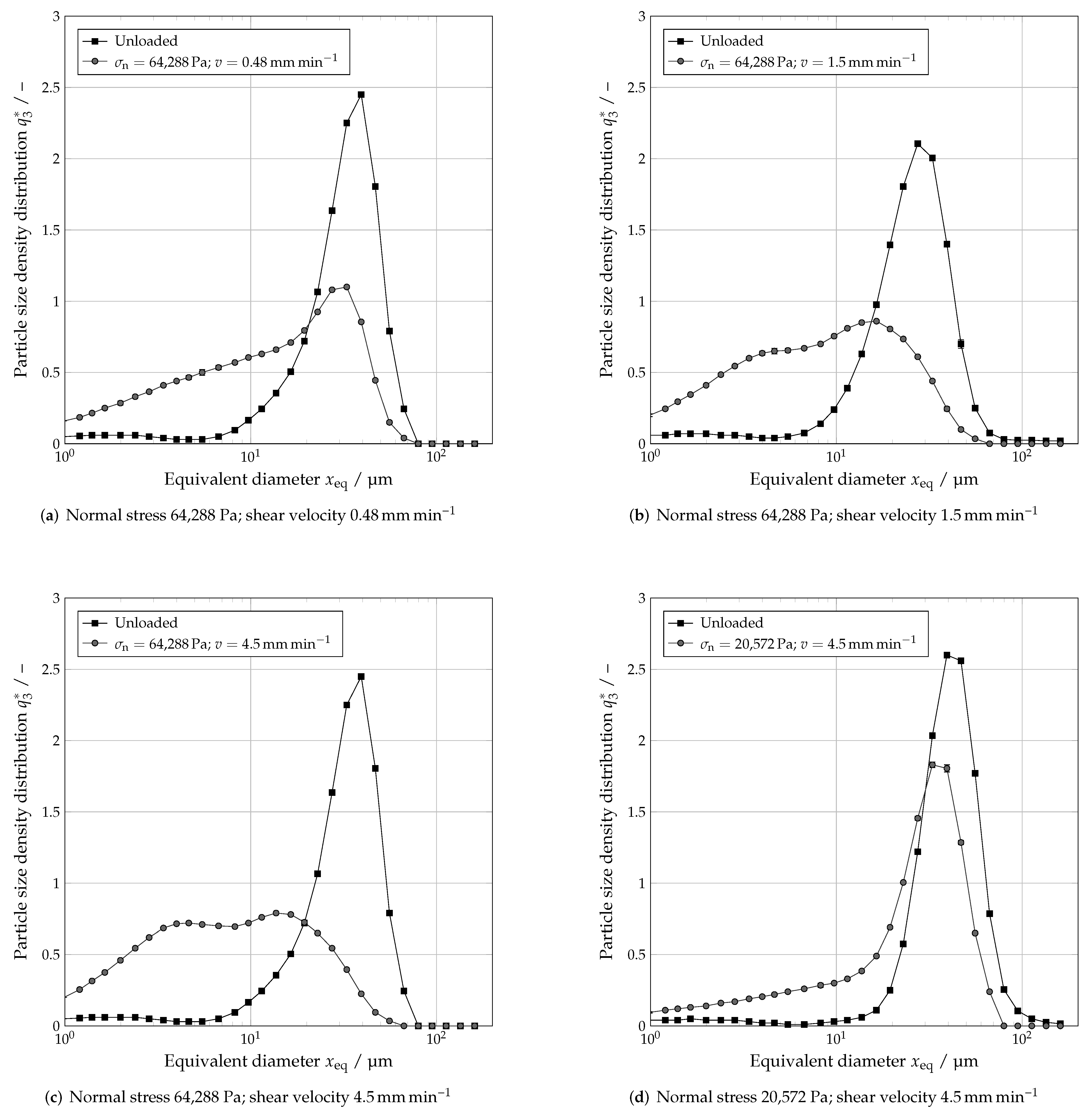
4.3. Influence of Shear Velocity
5. Conclusions
Author Contributions
Funding
Institutional Review Board Statement
Informed Consent Statement
Data Availability Statement
Conflicts of Interest
Abbreviations
| µCT | Micro Computed Tomography |
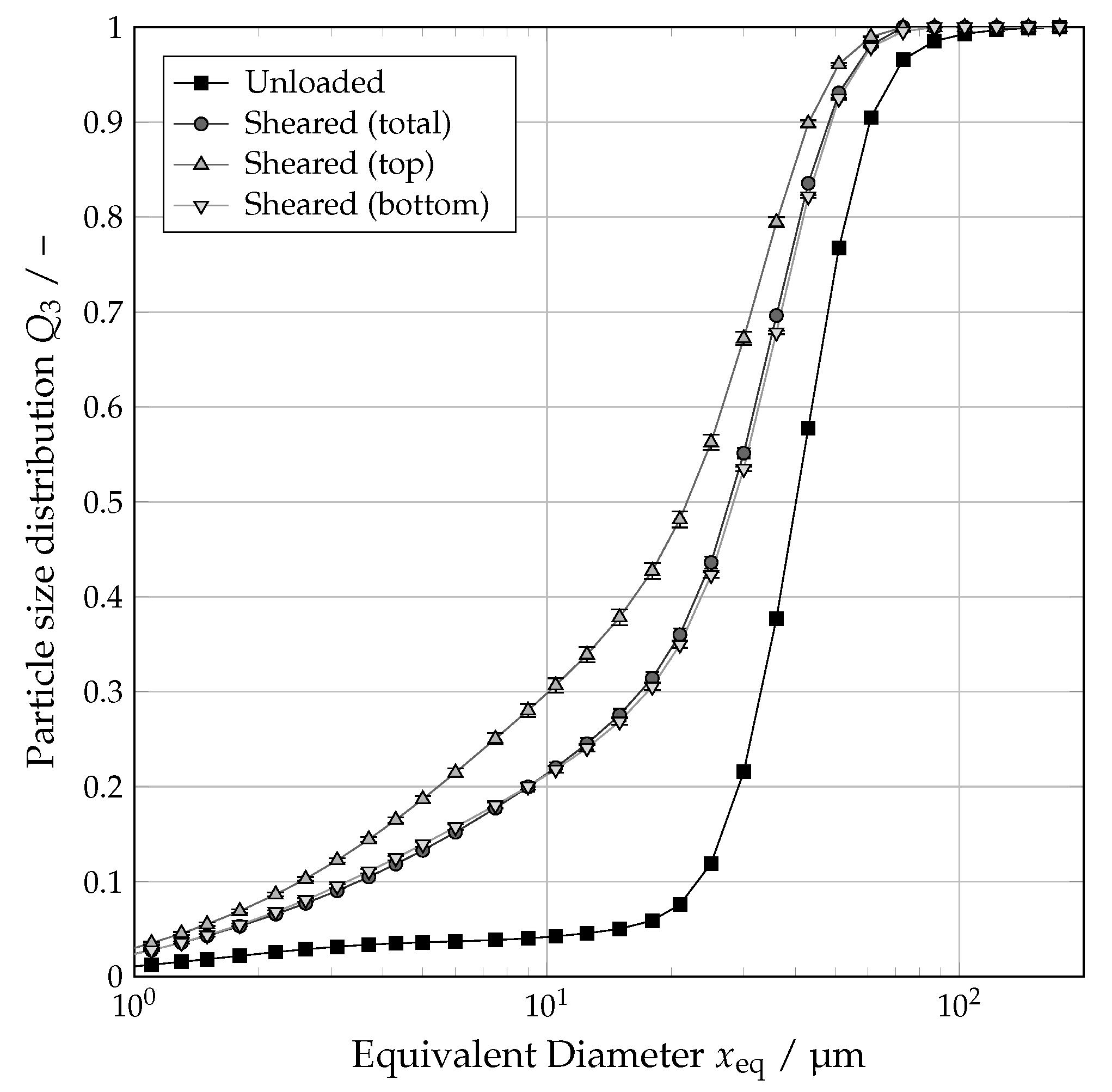
| PSD | Particle Size Distribution |
References
- Hubbuch, J.; Kind, M.; Nirschl, H. Preparative Protein Crystallization. Chem. Eng. Technol. 2019, 42, 2275–2281. [Google Scholar] [CrossRef] [Green Version]
- Basu, S.K.; Govardhan, C.P.; Jung, C.W.; Margolin, A.L. Protein crystals for the delivery of biopharmaceuticals. Expert Opin. Biol. Ther. 2004, 4, 301–317. [Google Scholar] [CrossRef] [PubMed]
- Hekmat, D. Large-scale crystallization of proteins for purification and formulation. Bioprocess Biosyst. Eng. 2015, 38, 1209–1231. [Google Scholar] [CrossRef] [PubMed]
- Hallas-Møller, K.; Petersen, K.; Schlichtkrull, J. Crystalline and amorphous insulin-zinc compounds with prolonged action. Science 1952, 116, 394–398. [Google Scholar] [CrossRef] [PubMed]
- Groß, M.; Kind, M. Bulk Crystallization of Proteins by Low-Pressure Water Evaporation. Chem. Eng. Technol. 2016, 39, 1483–1489. [Google Scholar] [CrossRef]
- Radel, B.; Funck, M.; Nguyen, T.H.; Nirschl, H. Determination of filtration and consolidation properties of protein crystal suspensions using analytical photocentrifuges with low volume samples. Chem. Eng. Sci. 2019, 196, 72–81. [Google Scholar] [CrossRef] [Green Version]
- Radel, B.; Nguyen, T.H.; Nirschl, H. Calculation of the flux density function for protein crystals from small scale settling and filtration experiments. AlChE J. 2021, 67, e17378. [Google Scholar] [CrossRef]
- Dobler, T.; Radel, B.; Gleiss, M.; Nirschl, H. Quasi-Continuous Production and Separation of Lysozyme Crystals on an Integrated Laboratory Plant. Crystals 2021, 11, 713. [Google Scholar] [CrossRef]
- Barros Groß, M.; Kind, M. Comparative Study on Seeded and Unseeded Bulk Evaporative Batch Crystallization of Tetragonal Lysozyme. Cryst. Growth Des. 2017, 17, 3491–3501. [Google Scholar] [CrossRef]
- Walsh, G. Proteins, 2nd ed.; John Wiley & Sons Inc.: Hoboken, NJ, USA, 2014. [Google Scholar]
- Cornehl, B.; Overbeck, A.; Schwab, A.; Büser, J.P.; Kwade, A.; Nirschl, H. Breakage of lysozyme crystals due to compressive stresses during cake filtration. Chem. Eng. Sci. 2014, 111, 324–334. [Google Scholar] [CrossRef]
- Cornehl, B.; Grünke, T.; Nirschl, H. Mechanical Stress on Lysozyme Crystals during Dynamic Cross-Flow Filtration. Chem. Eng. Technol. 2013, 36, 1665–1674. [Google Scholar] [CrossRef]
- Jen, A.; Merkle, H.P. Diamonds in the rough. Pharm. Res. 2001, 18, 1483–1488. [Google Scholar] [CrossRef] [PubMed]
- Illies, S.; Pfinder, J.; Anlauf, H.; Nirschl, H. Filter cake compaction by oscillatory shear. Dry. Technol. 2016, 35, 66–75. [Google Scholar] [CrossRef] [Green Version]
- Höfgen, E.; Collini, D.; Batterham, R.J.; Scales, P.J.; Stickland, A.D. High pressure dewatering rolls: Comparison of a novel prototype to existing industrial technology. Chem. Eng. Sci. 2019, 205, 106–120. [Google Scholar] [CrossRef]
- Hammerich, S.; Stickland, A.D.; Radel, B.; Gleiss, M.; Nirschl, H. Modified shear cell for characterization of the rheological behavior of particulate networks under compression. Particuology 2020, 51, 1–9. [Google Scholar] [CrossRef]
- Tiller, F.M.; Lu, W.M. The role of porosity in filtration VIII: Cake nonuniformity in compression–permeability cells. AlChE J. 1972, 18, 569–572. [Google Scholar] [CrossRef]
- Schönert, K. The influence of particle bed configurations and confinements on particle breakage. Int. J. Miner. Process. 1996, 44–45, 1–16. [Google Scholar] [CrossRef]
- Liu, J.; Schönert, K. Modelling of interparticle breakage. Int. J. Miner. Process. 1996, 44–45, 101–115. [Google Scholar] [CrossRef]
- Rumpf, H. Grundlegende physikalische Probleme bei der Zerkleinerung. Chem. Ing. Tech. 1962, 34, 731–741. [Google Scholar] [CrossRef]

Publisher’s Note: MDPI stays neutral with regard to jurisdictional claims in published maps and institutional affiliations. |
© 2022 by the authors. Licensee MDPI, Basel, Switzerland. This article is an open access article distributed under the terms and conditions of the Creative Commons Attribution (CC BY) license (https://creativecommons.org/licenses/by/4.0/).
Share and Cite
Radel, B.; Gleiß, M.; Nirschl, H. Crystal Breakage Due to Combined Normal and Shear Loading. Crystals 2022, 12, 644. https://doi.org/10.3390/cryst12050644
Radel B, Gleiß M, Nirschl H. Crystal Breakage Due to Combined Normal and Shear Loading. Crystals. 2022; 12(5):644. https://doi.org/10.3390/cryst12050644
Chicago/Turabian StyleRadel, Benjamin, Marco Gleiß, and Hermann Nirschl. 2022. "Crystal Breakage Due to Combined Normal and Shear Loading" Crystals 12, no. 5: 644. https://doi.org/10.3390/cryst12050644
APA StyleRadel, B., Gleiß, M., & Nirschl, H. (2022). Crystal Breakage Due to Combined Normal and Shear Loading. Crystals, 12(5), 644. https://doi.org/10.3390/cryst12050644