Article

Study of the Creep Behavior of Nickel-Based Single Crystal Superalloy Micro Specimens with Dimensional Effects

Aecc Hunan Aviation Powerplant Research Institute, Zhuzhou 412002, China
*
Author to whom correspondence should be addressed.
Crystals 2022, 12(5), 592; https://doi.org/10.3390/cryst12050592
Submission received: 31 March 2022 / Revised: 20 April 2022 / Accepted: 21 April 2022 / Published: 22 April 2022
(This article belongs to the Special Issue Experiments and Simulations of Superalloys)

Abstract

:
Nickel-based single-crystal superalloys are widely used in aeroengine hot-end components, owing to their unique crystal structure and outstanding high-temperature mechanical properties. In the present study, round rod specimens of different sizes were subjected to high temperature creep tests at 980 °C/300 MPa of a second-generation nickel-based single crystal superalloy. The effect of size on the creep behavior of nickel-based single-crystal superalloys was studied with reference to the creep curves and microstructure morphologies. Creep interruption tests of 3-mm micro-round rod specimens were performed for 30, 60, and 90 h until creep fracture occurred. It was found that for nickel-based single crystal superalloys, the smaller the diameter of the specimen, the longer its creep life. Furthermore, the creep fracture morphology showed obvious creep cavitation in the fracture region. The law of organization evolution was used to analyze the rafting phenomena during the creep process. A typical “N”-type drifting strip structure was found during the creep process. Meanwhile, the width of the γ-phase channel increases continuously with creep, and the rate of change of the width of the matrix phase was fastest at the earliest stage of creep, slowing significantly during the middle and late stages of creep with the completion and appearance the rafting phenomenon.

1. Introduction

The breakthrough of Ni-based single-crystal alloy turbine blade technology has been crucial for the development of aero-engines. This has resulted in great advancements in the temperature-bearing capacity of blade materials and engine performance [1,2,3]. After decades of development, many milestones have been achieved in the study of the mechanical properties of Ni-based single-crystal high-temperature alloy materials [4,5,6]. The microstructure of these single crystals exhibits unique morphological characteristics and positional relationships between the γ phase and the γ matrix. The composition of the reinforcing γ phase is the metal compound Ni3Al, which is stable at high temperatures and has a strengthening effect on the mechanical properties of the material [7,8]. Compared with conventional high-temperature alloys, Ni-based single crystals show eliminated grain boundaries, reduced regions of crack initiation, and good resistance to high temperatures, corrosion, fatigue, and oxidation. These properties enable them to be used in large quantities in the manufacture of aero-engine blades [9]. Ni-based single crystals are anisotropic materials that exhibit a sensitive crystal orientation dependence [10]. Under unidirectional stress, they form interesting relationships between crystal orientation, temperature, tensile state, and strain rate. These properties are different from those of conventional materials; therefore, new mechanical characterization and modeling methods must be investigated. To improve the overall performance of aero-engines, it is necessary to increase the reserve of mechanical properties of materials and improve their production and processing levels. In addition, size effects, including sample size [6], grain size [11], contact size [12], and microstructure characteristic length [13], on the mechanical properties of materials are also a topic of interest for researchers at present. In terms of mechanics, research to date has largely focused on creep and fatigue properties. Prastiti [4] and Karamitros [5] studied the fatigue crack nucleation and crack propagation mechanism of nickel-based single crystal based on crystal plasticity theory. The model proposed in the literature can accurately identify the crack nucleation position and predict the crack growth rate and path.
Because aero-engines, especially their hot-end components, are exposed to high temperatures for long periods of time, creep deformation of the material occurs. In a simple analysis, the accumulation of time at constant temperature and load conditions slowly leads to the complete deformation of the material [14]. The extraordinary creep properties of Ni-based single crystals significantly impact the safety index and driving reliability of aero-engines and are an important reason for their use as engine materials. The properties of these materials must be studied separately because their mechanical behavior differs from that of conventional materials.
The creep process of Ni-based single crystals is divided into three main phases [15]: a short deceleration phase, a steady-state phase, and an accelerated creep phase. The first and second stages are prolonged when the temperature is lowered or the stress is reduced, but the three phases of the creep curve remain [16]. There is a close causal relationship between the creep behavior of Ni-based single crystals and the morphology of their microstructures. Under prolonged temperature stress, the γ′ phase undergoes directional coarsening and selectively grows in a given direction according to a certain pattern, which is a phenomenon specific to the creep of Ni-based single crystals known as rafting [17]. The rafting phenomenon is an important factor affecting the creep–fatigue life of nickel-based single crystals. Pollock et al. experimentally investigated the high-temperature creep properties of CMSX-4 characterized by the directional coarsening of the γ′ phase, proposed fine-scale factors affecting rafting, and established a relevant rafting model [18]. Numerous studies have shown that rafting in Ni-based single crystals is closely related to the magnitude of the test temperature and stress value [19].
Another study noted that the microstructural evolution of Ni-based single crystals is closely related to both the dislocation structure and dislocation motion of the γ′ phase, where the edge portion of the γ′ phase grows preferentially and expands slowly to connect with the surrounding phases, forming a raft-like structure [20]. By observing the kinematic evolution of a Ni-based single-crystal structure, Pearson et al. found that the directional diffusion of alloy elements accompanied the raft structure process and that the stress gradient influenced the alloy creep. It was also noted that the elements within the matrix and reinforced phases diffused in opposite directions [21]. According to the currently accepted model, the motion of dislocations during the creep process causes a nonuniform stress distribution accompanied by a decrease in the energy of the system, and this driving force is responsible for the directional coarsening of the γ′ phase [22]. Changes in the structure and morphology of the γ phase strongly influence the creep properties of the material and determine the macroscopic properties of single-crystal blades in the service environment [23]. Pearson et al. [21] considered rafting as a hardening process that favors the properties of Ni-based single crystals and inhibits dislocation. It has also been suggested that the change in the structure of the γ phase during rafting is softening behavior [24].
Several factors affect the creep properties of Ni-based single-crystal materials. Numerous studies have found that temperature and stress of different magnitudes, crystal orientation in the principal stress direction, and lattice mismatch play important roles in the microstructural evolution of Ni-based single crystals [25,26]. Reed et al. conducted creep tests with different temperature stresses, finding that the γ phase underwent directional coarsening and rafting only at low-stress states at temperatures greater than 900 °C [27]. It was concluded that Ni-based single crystals are more prone to raft deformation at high temperatures and low stresses, which reduces the critical stress for atomic diffusion. There is also a correlation between the crystal orientation and rafting, with significant differences in the form of creep rafting for the three orientations of Ni-based single crystals [001], [011], and [111] under uniaxial stress conditions [28,29,30].
At this stage, most studies on the mechanical behavior and characterization of Ni-based single crystals, and creep mechanisms in particular, are based on tests conducted on standard-size specimens. This experimental method outlined in this study provides an effective analysis route to study the evolution of the creep–fatigue microstructure of Ni-based single-crystal materials and their creep–fatigue damage life. Unfortunately, experimenting with standard parts is not economical due to the high cost of Ni-based single-crystal materials. Nevertheless, it is necessary to develop a creep–fatigue study method for Ni-based single crystals based on miniature specimens. The reason for this is that in the strength assessment of some engine blades, specimens need to be cut directly from the turbine blades, and there are significant dimensional differences between the cut samples and standard parts. When the Ni-based single-crystal turbine blades are sampled again, the specimens obtained are often very small. In this study, a small specimen creep technique was developed based on a domestic single-crystal superalloy. By conducting high-temperature creep tests, the microstructure of Ni-based single-crystal materials and its evolution under creep loading were investigated, and the effect of specimen size on creep performance was analyzed. Furthermore, the creep failure mechanism of differently sized specimens was revealed from a microscopic perspective. The overarching aim of this study was to prevent the occurrence of catastrophic events by promoting the development and application of Ni-based single-crystal materials in China by studying their mechanical properties and service life at a reduced test cost.

2. Experimental Materials and Methods

2.1. Test Material

The test material used was a second-generation Ni-based single-crystal high-temperature alloy commonly used in engine turbine blades. The master alloy was melted in a vacuum induction furnace, re-melted in a vacuum directional solidification furnace, and subsequently poured into a single-crystal test bar. The parent alloy was supplied in the cast state and subjected to standard heat treatment methods (1290 °C, 1 h; 1300 °C, 2 h; 1315 °C, 4 h/AC; 1120 °C, 4 h/AC; 870 °C, 32 h/AC), with the crystal orientation in the [001] direction and the deviation of the crystal orientation controlled to within 10°. The main elemental components are listed in Table 1.
The initial composition observed by scanning electron microscopy is shown in Figure 1. The mosaic region in Figure 1a is the γ´ reinforced phase of the alloy, whose main component is the metal compound Ni3Al, which is the predominant reason for the excellent properties of the alloy. The γ´ phase is sterically ordered and co-grid in the γ phase. Using Image-J image processing software, the volume fraction of the γ’ phase, size of the reinforced phase, and width of the γ matrix were calculated to be approximately 66%, 0.4–0.6 μm, and 50 nm, respectively. Figure 1b shows the unit cell diagram of Ni-based single crystal superalloy. Figure 1c indicates a single crystal structure for the samples which includes a strong peak with a distinct crystalline diffraction line. Figure 1d shows the EDS composition results.

2.2. Test Method

A series of round bar specimens of varying sizes were used for the creep tests, which were divided into standard round bar specimens, round bar specimens, and miniature round bar specimens, with diameters of 5.0, 3.0, and 2.5 mm, respectively. The specific dimensions of the specimens are shown in Figure 2a–c, and the physical drawings of the three different round rod specimens are presented in Figure 2d.
The test was conducted in full accordance with the Metal Tensile Creep and Durability Test Method (GB/T2039-1997), and all creep tests were completed on a CSS-2910 (SINOTEST, Changchun, China) high-temperature creep machine. The entire creep test was conducted in a high-temperature furnace. The test took place in air, and thermocouples were used for temperature acquisition. The temperature difference within the specimen was controlled to within 0.5 °C to reduce the test error. Each test started 30 min after the target temperature was reached.
The test conditions were tailored for the purpose of this study. The effect of specimen size on the creep properties of Ni-based single crystals was investigated and uniaxial tensile creep tests were performed at 980 °C/300 MPa on three different sizes of specimens with diameters of 2.5 mm, 3 mm, and 5 mm, respectively, and the corresponding creep curves were plotted. In particular, the evolution of the microstructure during high-temperature creep was studied, and creep interruption tests were performed on the 3-mm specimens for periods of 30, 60, and 90 h at 980 °C. Full-life tests were also performed on 3 mm specimens at 980 °C until specimen fracture occurred.
After the test, small squares and specimen fractures were cut by wire, polished with sandpaper, and then machine-polished until smooth. Subsequently, the corrosion solution was prepared, containing a fixed ratio of concentrated HNO3 solution, hydrofluoric acid (HF), and propanetriol. Finally, the changes in the microstructure and characteristics of the fracture morphology were observed using a Zeiss scanning electron microscope (SEM, Carl Zeiss AG, Oberkochen, Germany).

3. Experimental Results and Discussion

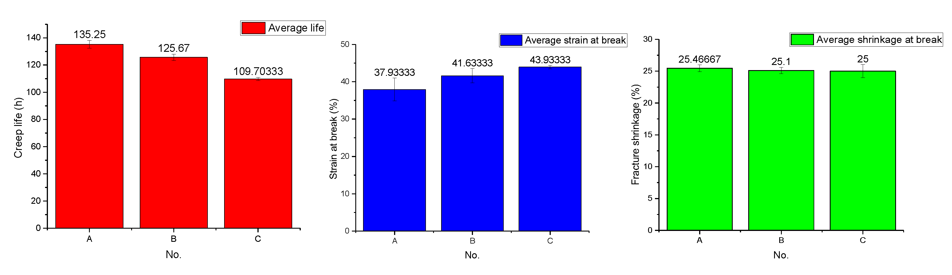
3.1. Effect of Size on Creep of Ni-Based Single Crystals

High-temperature creep tests were conducted on specimens of domestic second-generation single-crystal superalloys of different diameters (2.5, 3, and 5 mm) at 980 °C and 300 MPa. The test conditions and methods were kept the same, and only the specimen diameters were varied. The creep test results, including creep life, creep fracture strain, and cross-sectional shrinkage, are listed in Table 2.
From the test results (Table 2 and Figure 3), it can be seen that the miniature specimen exhibits the longest creep life for constant temperature stress, i.e., 980 °C/300 MPa. All dimensions were tested in triplicate. For the specimen with a diameter of 2.5 mm, the creep life is 139.22 h, 134.19 h, and 132.34 h, respectively, with little difference. The strains at break are 36.4%, 35.2%, and 42.2%, respectively, and the strain at break of A3 is larger. The fracture shrinkage rates are 26.1%, 24.8%, and 25.5%, respectively, with a small difference; for the specimen with a diameter of 3.0 mm, the creep life is 122.93 h, 125.42 h, and 128.66 h, respectively. The strains at break are 43.3%, 42.7%, and 38.9%, respectively, and the strain at break of B3 is smaller. The fracture shrinkage rates are 25.6%, 25.3%, and 24.4%, respectively, and the difference is small; for the specimen with a diameter of 5.0 mm, the creep life is 108.33 h, 111.27 h, and 109.51 h, respectively. The strains at break are 44.6%, 43.4%, and 43.8%, respectively. The fracture shrinkage rates are 24.7%, 26.4%, and 23.9%, respectively, and the fracture shrinkage rate of C2 is larger. To sum up, in general, the difference between the test results is small and within the acceptable range.
The average creep life was found to be approximately 125.67 h, whereas the average creep life of the 5 mm specimen was approximately 109.7 h. The maximum difference in creep life between the three specimens was 25.55 h, indicating a clear correlation between the size of the specimen and its creep life under these test conditions. Overall, the smaller the specimen size, the longer its creep life. It was also observed that at this temperature stress, the average strain at fracture of the 2.5-, 3- and 5-mm specimens was approximately 37.9%, 41. 6%, and 43.9%, respectively. This result indicated that the larger the size of the specimen, the larger the creep fracture strain. In general, the size of the specimen had no significant effect on the creep fracture strain. After calculating the average shrinkage rate of each specimen after creep, it was found that there was no significant difference in the shrinkage rate of the three different sizes of round bar specimens, which were all approximately 25%, and obvious necking occurred.
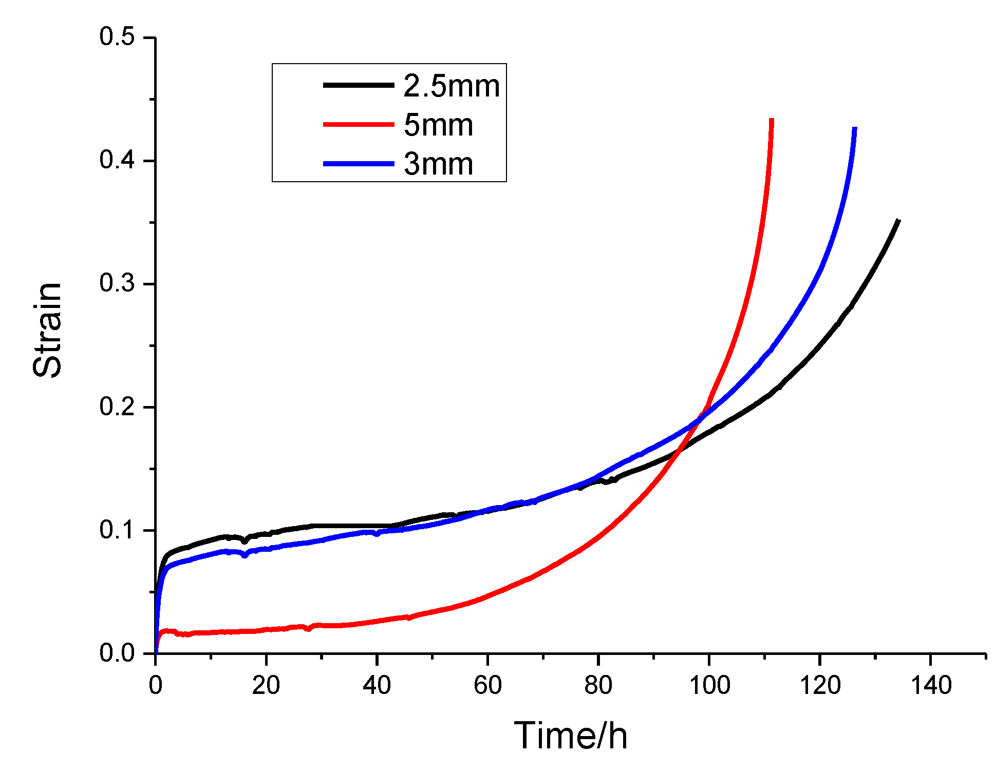
It can be seen from Figure 4 above that the creep curves of all three specimen sizes show exponential growth at the same temperature stress (980 °C/300 MPa). The analysis shows that the specimen with a diameter of 2.5 mm exhibits three obvious stages of creep deformation, first presenting a typical initial creep stage, also called the deceleration creep stage. In this stage, an obvious hardening of the creep process occurs, the creep strain is generated instantaneously with the loading of the stress, and the creep strain rate decreases dramatically until it reaches a minimum value. This stage was very short, lasting approximately 1.5 h, before rapidly entering the second stage of creep. The second stage is the steady-state creep stage, in which the creep rate remained stable and can be approximated as a straight line with a gradient of approximately 3.86 × 10⁻³/h. This stage lasted approximately 120 h, accounting for 88% of the total creep life, but the strain only increased by ~0.18. Subsequently, the third stage of creep was entered with a higher creep rate and shorter time, also known as the accelerated creep stage.
The creep strain rate increased monotonically, with strain increasing to a maximum value of 35.2%, at which point the specimen showed damage failure. By analyzing the creep curve for a diameter of 3 mm, it was found that the behavior was still in agreement with standard creep characteristics. The same short deceleration creep stage was observed, quickly followed by the stable second stage. This second stage involved ~115 h of slow, uniform growth, accounting for 90% of the total creep time. In the very short third stage, the creep strain rate was found to change dramatically in a sharp upward trend and finally increased to 42.7% at the point of fracture. Analysis of the 5-mm creep curve diameter shows that the creep strain in the first 5 mm of the third stage is significantly smaller than the other two sizes tested. Moreover, there is no obvious first stage, meaning direct entry into the second stage, when the creep rate is very slow and smooth, with a rate of approximately 2.41 × 10⁻³/h. The total time spent in this stage was ~99 h, accounting for 89% of the total creep time. When entering the third stage, the creep strain increased significantly from 18% in the second stage to 43.4%, i.e., by a factor of almost 2.4. The creep strain rate also showed a sharp increase, which finally led to the fracture of the specimen.
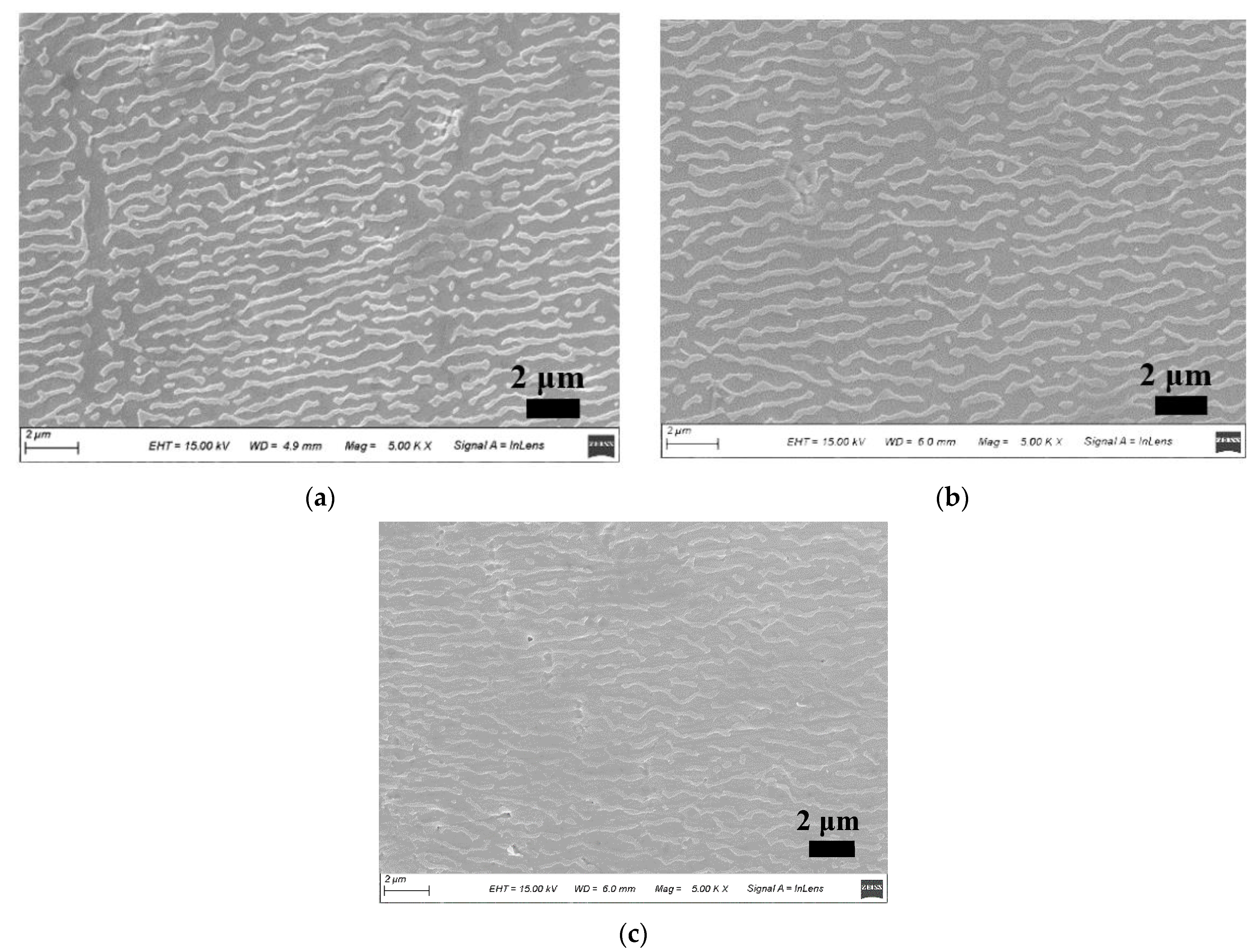
Figure 5 shows the microstructural morphology of round bar specimens with diameters of 2.5, 3, and 5 mm near the point of high-temperature creep fracture at 980 °C/300 MPa. Figure 5a shows the microstructural morphology of the 2.5-mm diameter specimen, where the initial cubic γ phase evolves into a slender strip-like raft structure in the horizontal direction after creep (i.e., the classical “N” type raft structure). At this point, the γ matrix phase channels in the vertical direction were found to almost completely disappear and those in the horizontal direction fused, forming a single piece with increasing width. The two adjacent γ phases in the horizontal direction were further elongated and thickened in the horizontal direction owing to the disappearance of the matrix phase between them, and the γ′ phases fused on meeting. After approximately 134 h of creep, a small part of the raft-like structure fractured into fragments. The creeping raft-like structure gradually lost its ability to resist deformation and appeared to be delaminated, which finally manifested as macroscopic damage and destruction of the alloy material.
Figure 5b shows the SEM images of the 3-mm creep specimen, from which it can be seen that a creep rafting phenomenon is also evident; however, the coarsening length of the γ phase in the horizontal direction is larger than that of the former. Although the changes in microstructure were similar, the creep time of the specimen was approximately 125 h. The occurrence of the raft shape also accompanies creep fracture, but the degree is much weaker than that of the former, and there are only a few scattered raft disintegration structures. Figure 5c shows the microstructure of a standard specimen with a diameter of 5 mm under the same test conditions. The creep life of this specimen was approximately 111 h. Compared with the first two microstructure images, the extension size of the γ phase along the horizontal direction increased. Furthermore, the connection formed a complete raft-shaped strip structure with almost no interruption, and the reinforced phases were connected in bunches and strips. There was no fragmented structure observed, indicating that the raft shape had not yet formed. Other defects are also visible, such as inclusion cracks, which are often responsible for creep damage and lead to a significantly shorter creep life and faster damage.
Figure 5 shows that, for specimens of different sizes, the microscopic morphology after creep rupture is the key to dominating the creep behavior. For the sample with a diameter of 2.5 mm (Figure 5a), the strengthening phase γ’ did not completely connect into a plate shape, and the degree of rafting is small. The channel of the matrix phase γ is narrow, and its life is longer. For the sample with a diameter of 5.0 mm (Figure 5c), the strengthening phase has a high degree of rafting, which has been approximately completely connected into a plate shape. The width of the matrix phase γ channel is wider and there are obvious holes, which accelerate the creeping, Therefore, larger size specimens have shorter creep life.
These results indicate that under the given conditions at 980 °C, the creep life of Ni-based single crystal alloys decreases with increasing specimen size. This, in turn, leads to the difference in the presence and shape of rafts for each size specimen. Thus, it can be concluded that the size of the specimen is closely related to the morphology and microstructure of the alloy, and more closely related to the creep persistence performance.
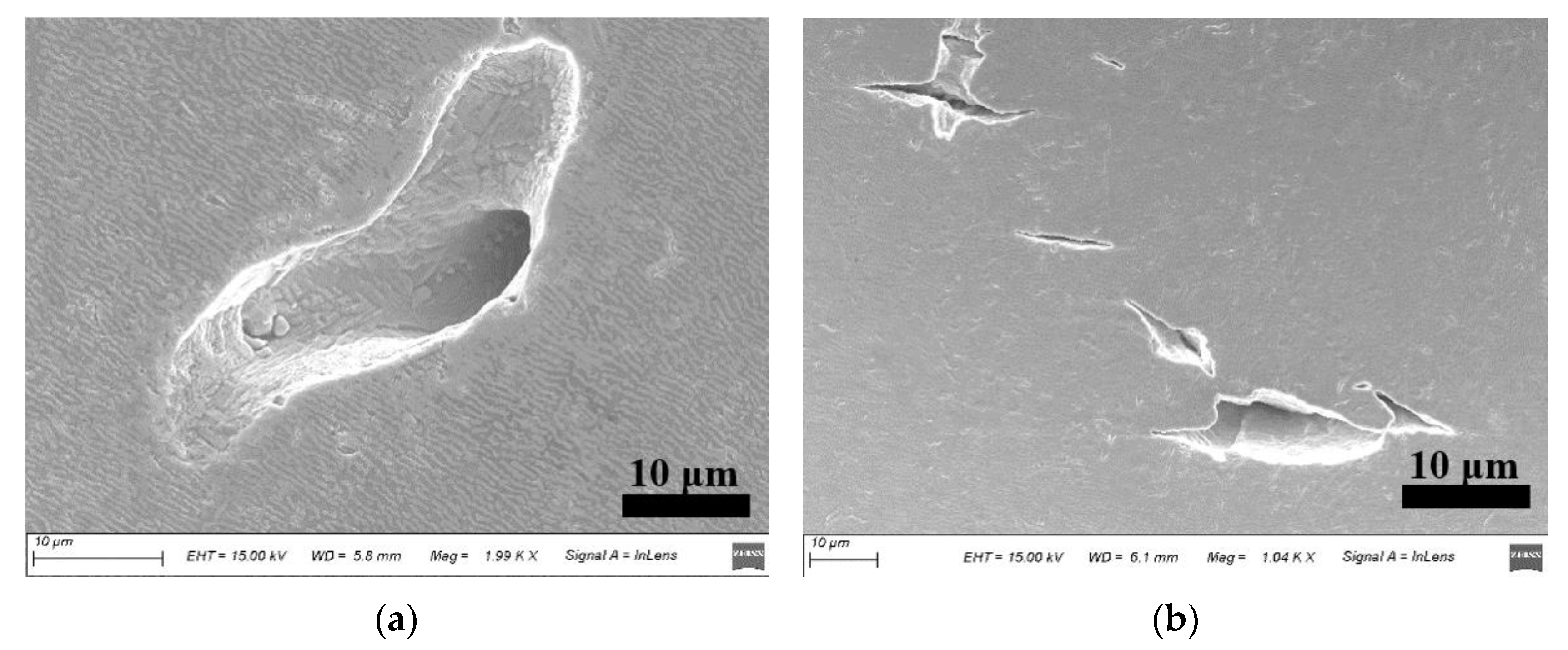
SEM was used to observe the microstructural morphology around the creep fracture of the superalloy at 980 °C/300 MPa, where a large number of crack sources could be seen. A large, elliptical hole defect can be seen in Figure 6a, and the γ phase near this region has been oriented and coarsened to form a thinly striped raft-like structure, i.e., an “N”-shaped raft. The presence of the hole defect interrupts the continuity of the γ phase, resulting in the raft-like γ phase around the hole being significantly distorted. The hole was identified as a casting defect in the material that severely disrupted the continuity of the tissue and thus affected the creep life of the Ni-based superalloy. Similarly, many defects can be seen in Figure 6b, including cracks, inclusions, and holes. Casting defects are one of the most important influencers of creep life. Microdefects gradually expand and extend with creep, leading to a decrease in the effective bearing area of the specimen and an increase in the actual stress in the cross-section, which eventually leads to creep fracture.
Figure 7 shows that after a long period of high-temperature creep testing, the surface of the Ni-based alloy underwent severe oxidation, and a thick oxide layer with bright white color was formed on the surface of the specimen. A large number of pores and cracks were observed near the oxide layer, causing a reduction in the finite cross-sectional area. However, the deformation resistance of the oxides (for example, Al2O3) in the oxide layer is not equal to that of the base alloy, and the deformation rate of the oxide layer is smaller. The uncoordinated deformation during creep causes cracks in the oxide layer, which in turn results in the fracture of the Ni-based single crystal and leads to a reduction in creep life.
In summary, it can be concluded that under the same test conditions, the smaller the size of the specimen, the longer its creep life. In addition to the errors caused by the test process, such as the error of the testing machine, test operation, dispersion of test data, dimension processing, and the analysis of the causes of such differences in test results from the perspective of creep damage, there are two main influencing factors. First, the casting defects of the material itself, including cracks, holes, and inclusions, cause a reduction in the effective bearing area during creep and eventually lead to specimen fracture. The 2.5-mm specimen, owing to its smaller volume and surface area, benefits from a reduced effective bearing area caused by the volume of the high-stress area. The possibility of defects or weak points is reduced, which in turn leads to the creep life of this specimen being extended. The second is the loss of the effective cross-sectional area due to oxidative corrosion on the specimen surface, leading to creep fracture due to the incompatible deformation of the oxide layer and the base alloy. Compared to standard specimens, miniature specimens are smaller in size, volume, and surface area, and have a smaller area for oxidation loss defects; therefore, in general, the smaller the specimen size, the longer the creep life.

3.2. Creep Process of Ni-Based Single Crystals at 980 °C/300 MPa

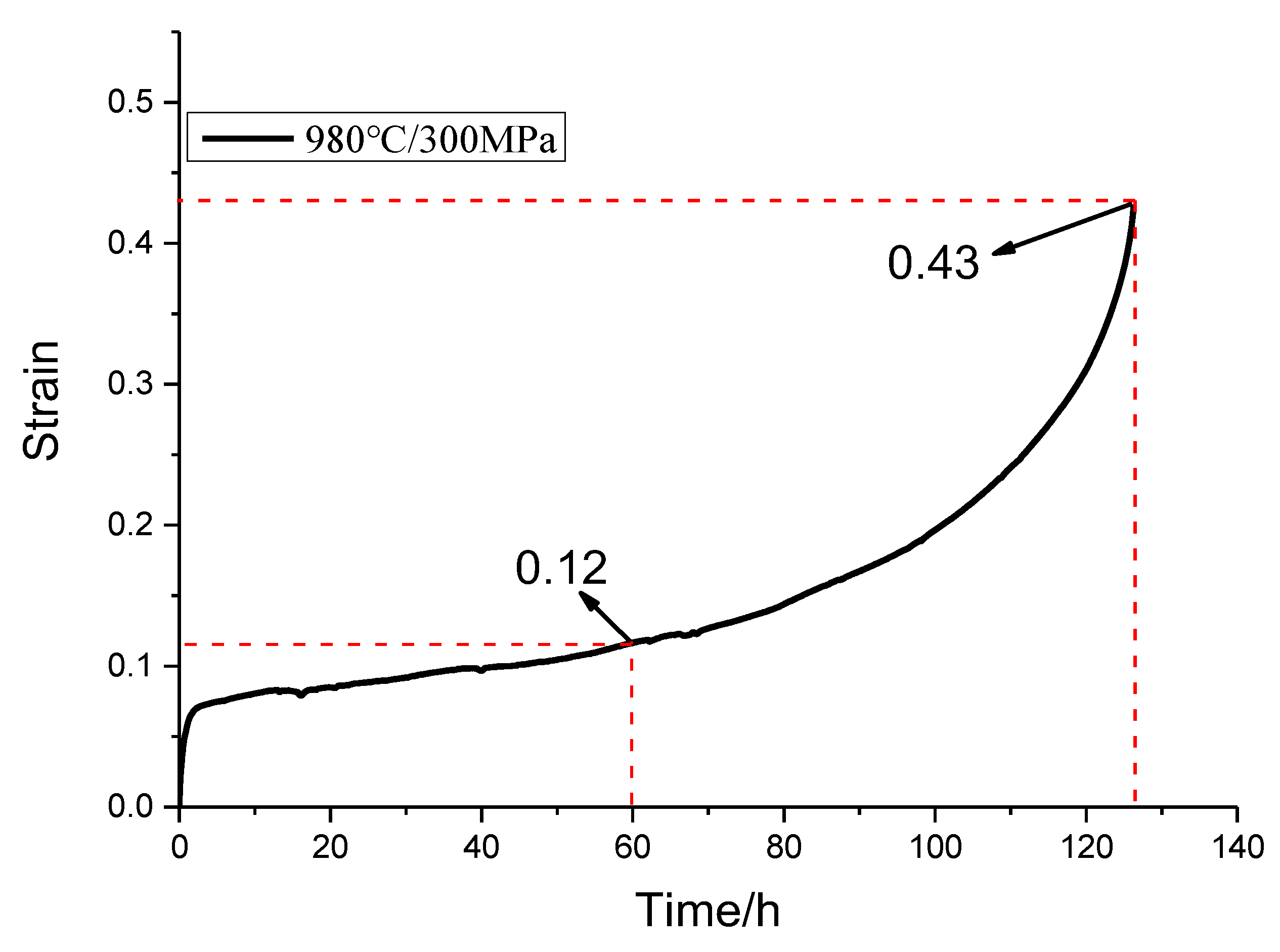
Creep interruption tests for periods of 30, 60, and 90 h and complete tests up to the point of fracture were carried out on Ni-based single-crystal superalloy specimens at 980 °C/300 MPa. These specimens were [001] oriented round bars with a diameter of 3 mm, whose full creep life curves are shown in Figure 8. The creep deformation is characteristically divided into three stages. In the first stage, the creep deformation rate decreased rapidly for a short time, typical of the creep deceleration stage. Contrast analysis of this creep process showed that this stage, the process of hardening and recovery of softening in a smooth state, accounts for a large percentage of the overall creep life. This is followed by a rapid transition to the second stage of creep. During the second stage, the creep strain grew smoothly and slowly, and the creep rate remained almost constant. At a creep time of 60 h, the creep strain was only 0.12. Finally, the third stage of creep was entered, which is the accelerated creep stage. At this point, the creep rate and creep strain suddenly and rapidly increased. The fracture occurred at approximately 125 h, at which point the strain reached 0.43. This additional value was relatively large, which finally led to the failure and destruction of the specimen.
Numerous studies have shown that the excellent properties of Ni-based single-crystal high-temperature alloys arise from their unique crystal structure, which changes during the creep process. To study the evolution of the microstructure during creep, the morphology of the specimens was observed and analyzed by scanning electron microscopy (SEM) for different periods of creep: 30, 60, and 90 h, and the final fracture moment.
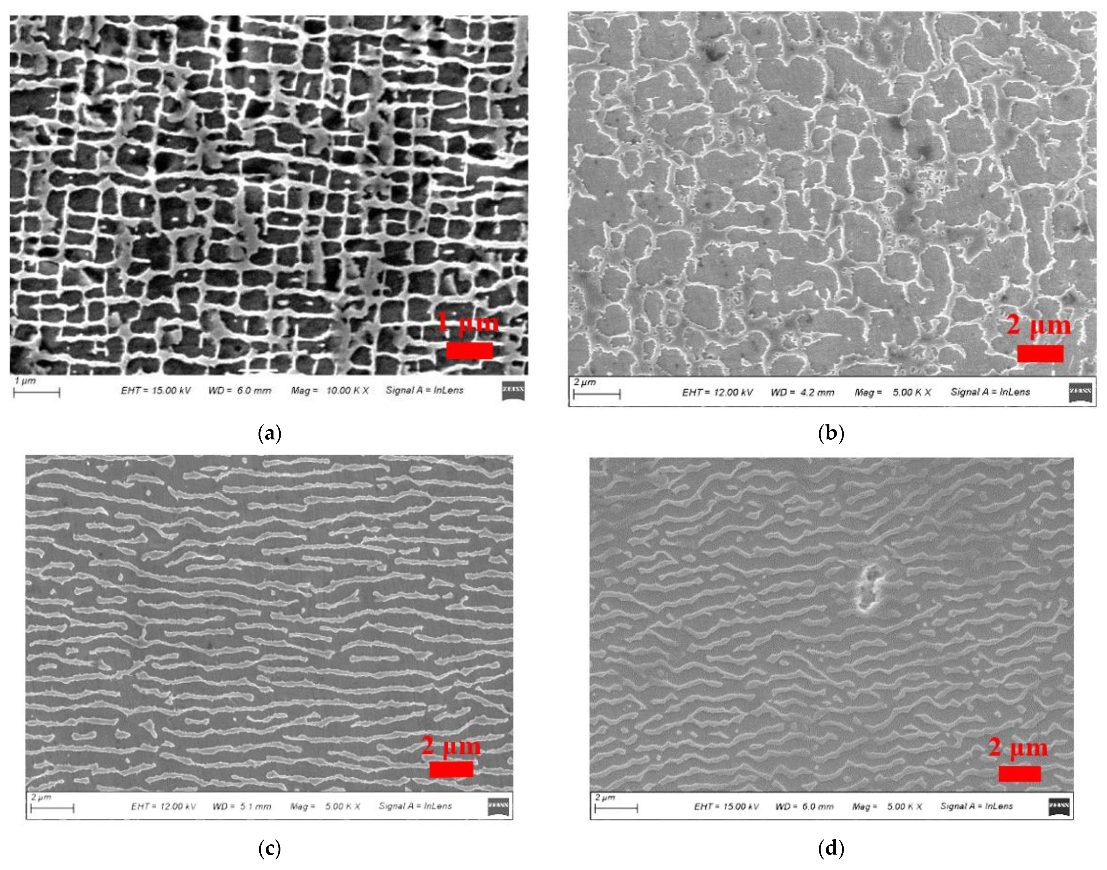
Figure 9 shows the microstructure morphology of the Ni-based single-crystal superalloy at different time points during creep at 980 °C/300 MPa test conditions. Figure 9a shows the microstructure morphology at the beginning of the second stage of creep—that is, the steady-state creep stage. It can be seen that the γ phase starts to change shape at this time; it is no longer the original uniform co-grid of the γ phase, and the initial raft shape occurs. The two γ-reinforced phases that are partially adjacent to each other are interconnected and show a trend of directional coarsening along the horizontal axis. Although the reinforced phase γ maintains a block-like structure, its grain size gradually increases, and the matrix phase passages start to widen. At this time, the size of the reinforced phase γ was approximately 0.5–0.6 µm. Figure 9b shows the microstructure of the superalloy during the middle stage of steady-state creep at 60 h. The two-phase structure is clearly deformed, the matrix phase channel in the horizontal direction slowly thicker, and the matrix channel in the vertical direction gradually became thinner or disappeared completely. The grain size of the γ′ phase has grown to 1.2–1.4 µm, and the surrounding cubic γ′ phase is passivated and has become round and elliptical. The position of the γ phase is disordered, and a raft-like structure was observed.
When the creep enters the end of the steady-state phase at 90 h, as shown in Figure 9c, the degree of deformation of the two γ/γ′ phases intensifies and significant rafting can be seen to have occurred. The two γ′ phases fuse together, join to form a strip, and continue to grow in the horizontal direction. The matrix channels in the vertical direction have completely disappeared, and the coarsening of the matrix phase channels in the horizontal direction has continued to expand severely, forming a typical “N”-type raft structure. From the above analysis, it can be seen that when the specimen was in the steady-state creep stage, the creep strain and creep rate were very low, and the microstructure indicated that the initial rafting phenomenon was not very obvious. Only the outcrop and γ phase morphology did not change significantly, meaning that good creep performance can be maintained for a long period of time. While rafting was observed in the middle of the steady-state creep stage, the width of the reinforced phase morphology and the matrix phase changed significantly; at the end of the steady-state stage, the γ phase coarsened to form a plate, the rafting phenomenon was complete, and the third stage of creep was about to be entered. As shown in Figure 9d, the microstructure of the specimen at the point of fracture was a partially fractured γ phase raft-like strip structure, in which there were many scattered points. The matrix phase channel almost entirely disappeared.
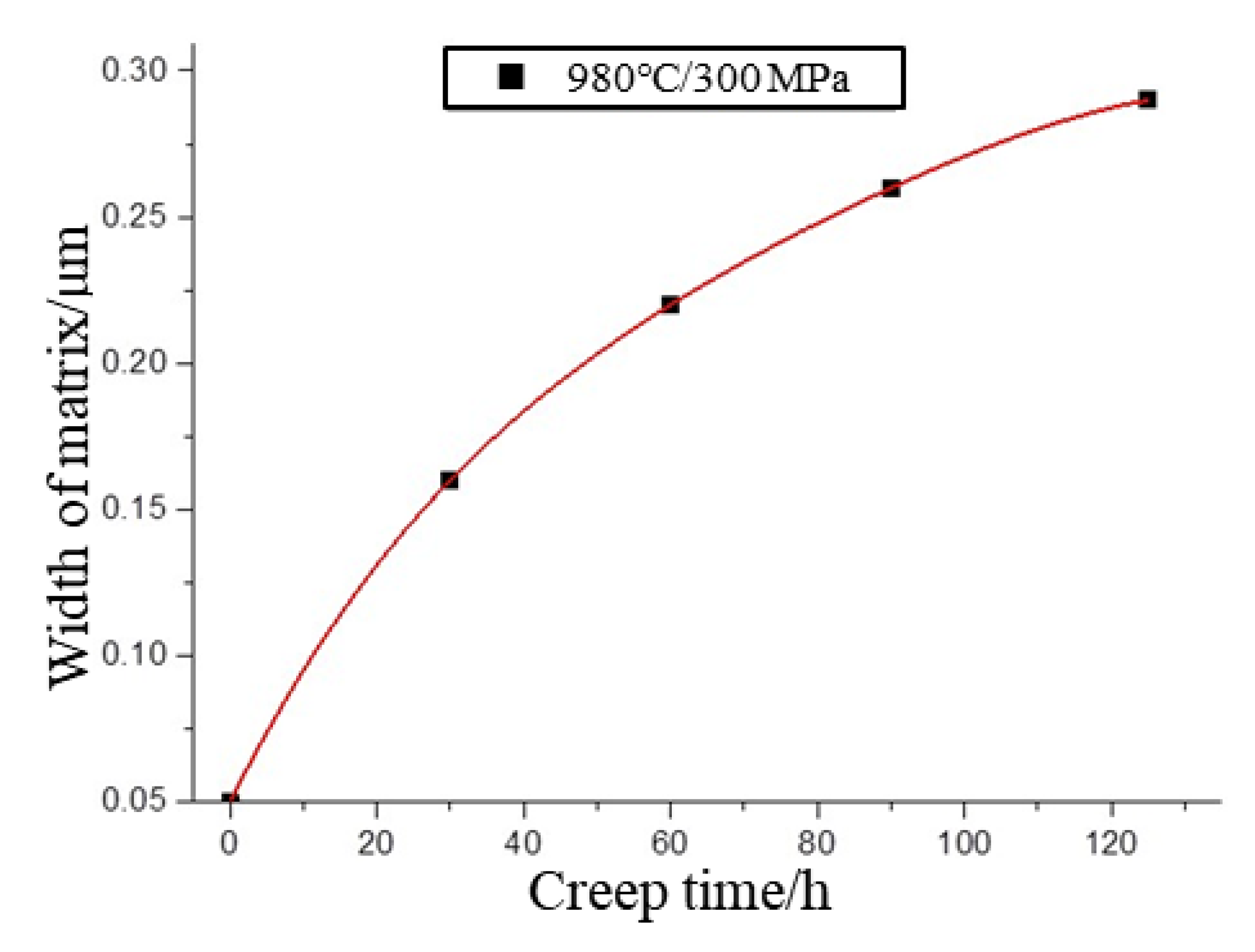
The above analysis shows that the width of the γ-phase channel continuously increases with the extent of creep during the high-temperature creep process. The γ-phase channel widths in the microstructural diagrams of the specimens for each process were statistically calculated using ImageJ image processing software. The statistical results showed that the sample values of the γ-phase channel widths at different creep moments obeyed a log-normal distribution. The γ-phase channel widths under tensile creep at 980 °C/300 MPa were fitted according to the mean value combined with the data processing software results, as shown in Figure 10. It can be observed that the rate of change of matrix phase width is fastest at the early creep stage, and this rate of increase slows down significantly in the middle and late creep stages with the appearance and completion of rafting. The analysis of the curves shows that the width of the matrix phase channel during creep exhibits a fast and then slow overall evolution.
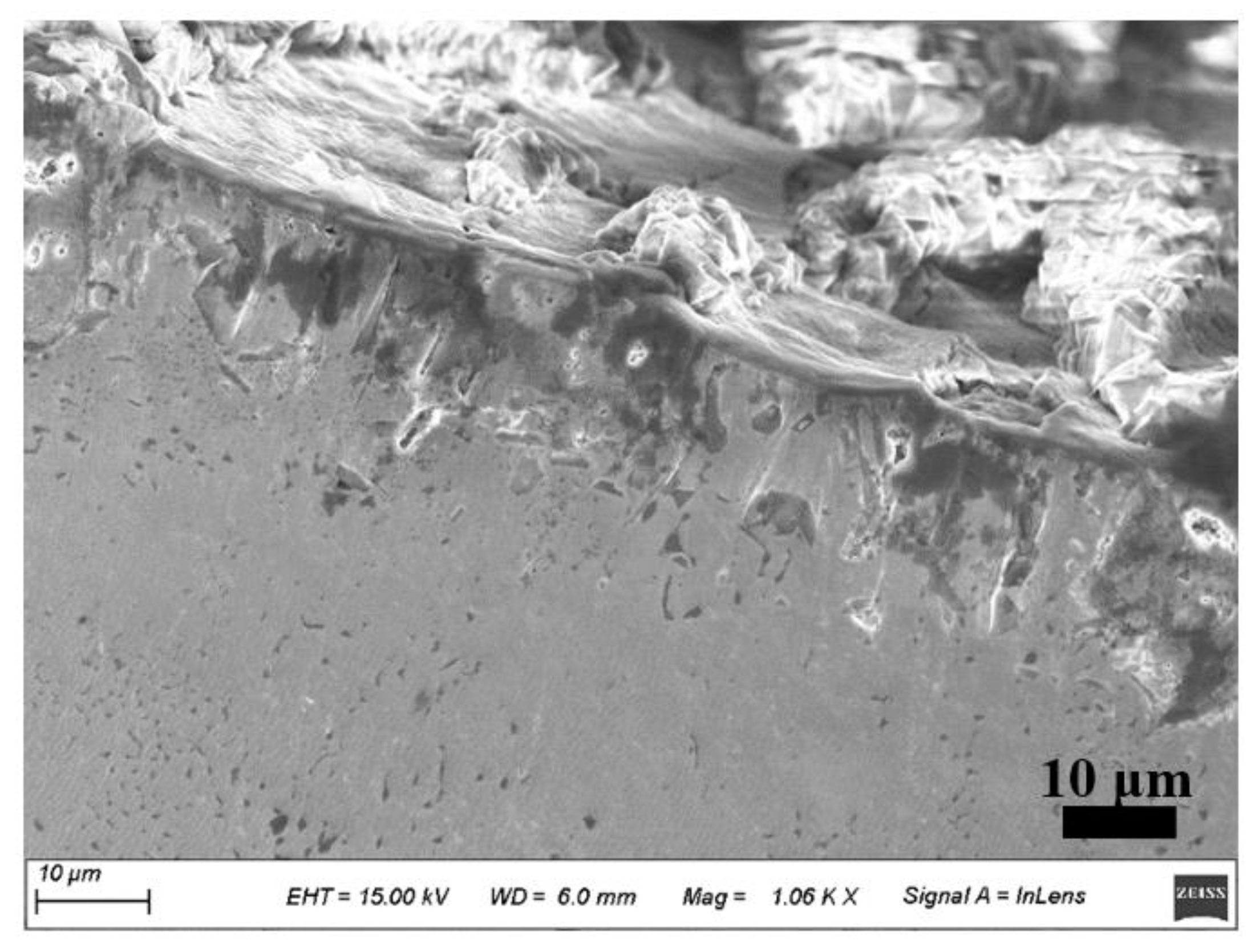
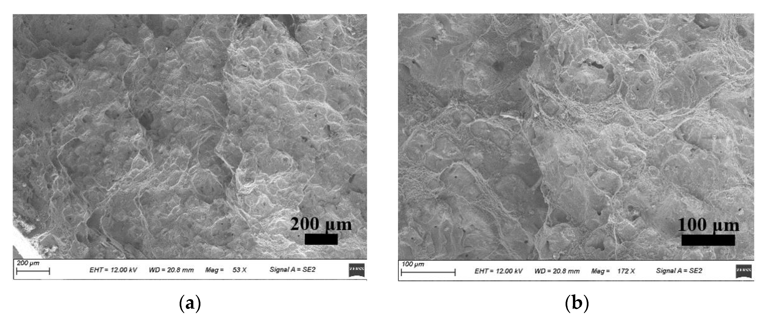
The creep fracture of the specimen at 980 °C/300 MPa is shown in Figure 11. The low-magnification morphology of the creep fracture of the material is shown in Figure 11a, where the fracture surface is relatively rough and oxidation is more severe. The deformation mechanism is mainly a diffusion creep mechanism with the directional diffusion of atoms and vacancies. This can be seen more clearly in the high-magnification image in Figure 11b: there is obvious creep cavitation in the fracture area with a large number of tough nests of different sizes. The center of these tough nests is often accompanied by many small holes, which are generally thought to be the source of crack budding, leading to creeping damage. Cracks sprout from the defect at the hole and expand radially, sometimes also causing the appearance of secondary cracks. The material collapses from the inside and finally shows the fracture pattern of holes and tough nests.
During high-temperature creep, a large number of dislocations slip or climb up the alloy matrix. Some dislocations shear into the reinforced phase, resulting in many holes near the interface between the matrix and reinforcing phases. This causes cracks to sprout and extend to form tough nests. Oxygen is able to enter from the holes and tough nests and subsequently react with Ni, Al, and other elements during oxidation, destroying the microstructure of the alloy and thus reducing its creep resistance. The cracks connect and extend towards each other, gradually forming tearing ribs in the direction of maximum shear stress, and finally, macroscopic fracture occurs in the late creep stage.
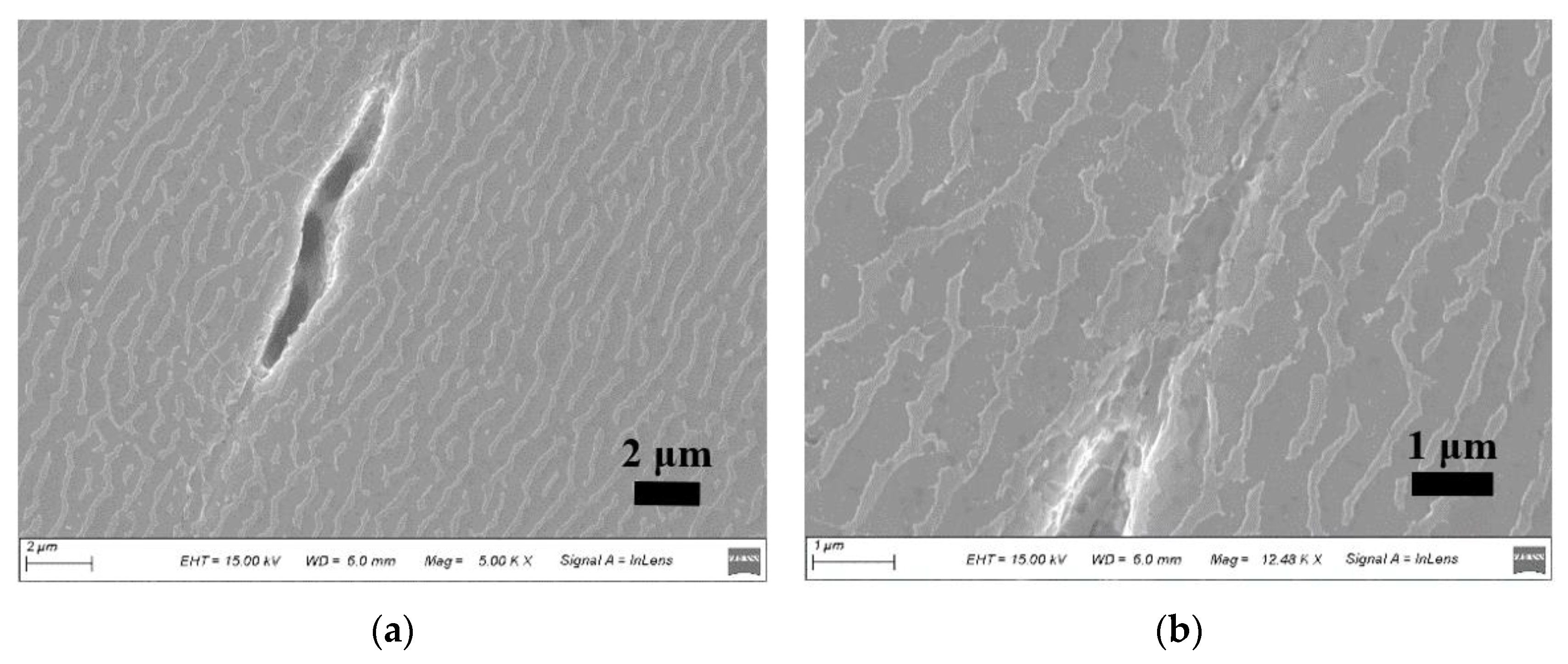
The microstructure morphology near the point of creep fracture of the Ni-based single-crystal superalloy was observed using SEM, and a large number of crack sources were found in the creep fracture region of the specimen. As shown in Figure 12a, the cracks were formed by the expansion of the original casting defects or initial microcracks during creep. Their expansion direction was perpendicular to the direction of the tensile axis, and the crack length was approximately 11.3 µm. At this point, the γ/γ phase exhibited an “N”-type raft structure. The γ phase striped raft structure was partially fractured, with many scattered points, and the matrix phase passages almost entirely disappeared. The rafting phenomenon was clearly present. Figure 12b shows the local enlargement of the crack tip, which is small in size and has a large stress concentration. The raft-like γ phase in this region is violently deformed with a large degree of tilting, the orientation of the raft-like γ phase is more disordered, and some small cracks exist in the region surrounding the crack.

4. Conclusions

In this study, creep tests were performed on three different sizes of Ni-based single-crystal specimens under the same test conditions of 980 °C/300 MPa. The effect of size on the creep properties of specimens was analyzed based on the test results and microstructure morphology observed by SEM. Finally, creep interruption tests were performed at different time points as well as full-life tests to the point of fracture on another round bar specimen with a diameter of 3 mm to investigate the evolution of the microstructure during high-temperature creep. The main conclusions are as follows.
  • Under the same test conditions, the effect of different specimen diameters on the creep life of Ni-based single crystals followed a clear trend. The smaller the diameter of the specimen, the longer its creep life. From the perspective of creep damage, the reason for this difference is that a reduction in specimen size equates to a smaller volume and surface area, and thus a smaller number and lesser extent of casting and oxidation loss defects are present. This results in a longer creep life.
  • Microstructure analysis of Ni-based single crystals at different time points during high-temperature creep shows that the γ phase thickens in the direction perpendicular to the stress axis, forming a typical “N”-type rafting strip structure. Meanwhile, the width of the γ-phase channel increases continuously with creep, and the rate of change of the width of the matrix phase was fastest at the earliest stage of creep, slowing significantly during the middle and late stages of creep with the completion and appearance the rafting phenomenon.
  • The creep fracture morphology showed obvious creep cavitation in the fracture region of the Ni-based single crystal, and the material started to fail from the inside, eventually showing holes and a tough-nest fracture morphology.

Author Contributions

Conceptualization, W.X.; Data curation, X.A.; Formal analysis, X.A. and Q.W.; Funding acquisition, X.A.; Methodology, J.W. and Y.Z.; Project administration, Y.Z. and H.Z.; Resources, H.Z.; Software, H.C.; Supervision, J.W.; Writing—original draft, W.X.; Writing—review & editing, S.Z. All authors have read and agreed to the published version of the manuscript.

Funding

This research was funded by Hunan Provincial Natural Science Foundation of China (NO.2019JJ50700) and Innovation Foundation of Aero Engine Corporation of China (NO.CXPT-2019-002).

Institutional Review Board Statement

Not applicable.

Informed Consent Statement

Not applicable.

Data Availability Statement

Not applicable.

Conflicts of Interest

The authors declare no conflict of interest.

References

  1. Pei, H.; Wen, Z.; Wang, Z.; Gan, W.; Lu, G.X.; Yue, Z. Transient thermal fatigue crack propagation behavior of a nickel-based single-crystal superalloy. Int. J. Fatigue 2020, 131, 105303. [Google Scholar] [CrossRef]
  2. Zhang, Y.; Wen, Z.; Pei, H.; Gan, W.; Yue, Z. Equivalent and Simplification of Nickel-Based Superalloy Plates with Close-Packed Film Cooling Holes. J. Mech. 2019, 35, 359–372. [Google Scholar] [CrossRef]
  3. Sun, X.F.; Jin, T.; Zhou, Y.Z.; Hu, Z.Q. Research Progress of Nickel-Base Single Crystal Superalloys. Mater. China 2012, 31, 1–11. [Google Scholar]
  4. Prastiti, N.G.; Xu, Y.; Balint, D.S.; Dunne, F.P.E. Discrete dislocation, crystal plasticity and experimental studies of fatigue crack nucleation in single-crystal nickel. Int. J. Plast. 2020, 126, 102615. [Google Scholar] [CrossRef]
  5. Karamitros, V.; Maclachlan, D.W.; Dunne, F.P.E. Mechanistic fatigue in Ni-based superalloy single crystals: A study of crack paths and growth rates. J. Mech. Phys. Solids 2022, 158, 104663. [Google Scholar] [CrossRef]
  6. Gao, P.; Sun, S.; Li, H.; Niu, R.; Han, S.; Zong, H.; Wang, H.; Lian, J.; Liao, X. Ultra-strong and thermally stable nanocrystalline CrCoNi alloy. J. Mater. Sci. Technol. 2022, 106, 1–9. [Google Scholar] [CrossRef]
  7. Lu, L.; Chen, X.; Huang, X.; Lu, K. Revealing the Maximum Strength in Nanotwinned Copper. Science 2009, 323, 607–610. [Google Scholar] [CrossRef]
  8. Yang, F.M.; Sun, X.F.; Guan, H.R.; Hu, Z.Q. Low cycle fatigue behavior of K40s cobalt-base superalloy at elevated temperature. Acta Metall. Sin. 2002, 38, 1047–1105. [Google Scholar]
  9. Hou, N.X.; Yu, Q.M.; Wen, Z.X.; Yue, Z.F. Low cycle fatigue behavior of single crystal superalloy with temperature gradient. Eur. J. Mech. A/Solids 2010, 29, 611–618. [Google Scholar] [CrossRef]
  10. Gu, Y.; Wen, W.; Cui, H. Prediction of fretting fatigue life of dovetail joint under high-cycle and low-cycle load. J. Propuls. Technol. 2008, 29, 240–243. [Google Scholar]
  11. Balint, D.S.; Deshpande, V.S.; Needleman, A.; Giessen, E.V.D. Size effects in uniaxial deformation of single and polycrystals: A discrete dislocation plasticity analysis. Model. Simul. Mater. Sci. Eng. 2006, 14, 409–422. [Google Scholar] [CrossRef] [Green Version]
  12. Ruebeling, F.; Xu, Y.; Richter, G.; Dini, D.; Gumbsch, P.; Greiner, C. Normal Load and Counter Body Size Influence the Initiation of Microstructural Discontinuities in Copper during Sliding. ACS Appl. Mater. Interfaces 2021, 13, 4750–4760. [Google Scholar] [CrossRef] [PubMed]
  13. Xu, Y.; Gu, T.; Xian, J.; Giuliani, F.; Ben Britton, T.; Gourlay, C.M.; Dunne, F.P.E. Intermetallic size and morphology effects on creep rate of Sn-3Ag-0.5Cu solder. Int. J. Plast. 2021, 137, 102904. [Google Scholar] [CrossRef]
  14. Shi, H.; Ma, X.; Yu, T. Some new progresses on the research of creep and fatigue behaviors of high temperature structural materials. Chin. J. Solid Mech. 2010, 31, 696–715. [Google Scholar]
  15. Rao, S. Analysis of High-Temperature Creep of Aeroengines. Aircr. Engine 2004, 30, 10–13. [Google Scholar]
  16. Yue, Q.; Liu, L.; Yang, W.; Huang, T.; Sun, D.; Huo, M.; Zhang, J.; Fu, H. Research Progress of Creep Behaviors in Advanced Ni-based Single Crystal Superalloys. Mater. Rep. 2019, 33, 479–489. [Google Scholar]
  17. Cao, J.; Wang, Y.; Shi, D. A rafting model for creep of Ni base single crystal at high temperature based on microstructure cell. J. Aerosp. Power 2009, 24, 1691–1698. [Google Scholar]
  18. Pollock, T.M.; Argon, A.S. Directional coarsening in nickel-base single crystals with high volume fractions of coherent precipitates. Acta Metall. Mater. 1994, 42, 1859–1874. [Google Scholar] [CrossRef]
  19. Zhao, B.; Liu, G.; Hong, X. Study on high-temperature creep behavior of nickel-base single crystal supper alloy. Die Mould. Technol. 2017, 2, 9–12. [Google Scholar]
  20. Peng, Z. Direction coarsening of γ’ precipitates in a single crystal nickel base superalloy. Acta Metall. Sin. 1995, 31, 531–536. [Google Scholar]
  21. Pearson, D.D.; Lemkey, F.D.; Kear, B.H. Stress Coarsening of γ’ and Its Influence on Creep Properties of a Single Crystal Superalloy. Superalloys 1980, 513–520. [Google Scholar]
  22. Wu, W.; Guo, Y.; Wang, Y. Research progress on the directional coarsening behavior and high temperature creep mechanical properties in Ni-base superalloys. Adv. Mech. 2011, 41, 172–186. [Google Scholar]
  23. Wang, K.; Li, J.; Cao, C. Present Situation of Study on Creep Behavior of Single Crystal Superalloys. Mater. Eng. 2004, 1, 3–7. [Google Scholar]
  24. Henderson, P.J.; Mclean, M. Microstructural contributions to friction stress and recovery kinetics during creep of the nickel-base superalloy IN738LC. Acta Metall. 1983, 31, 1203–1219. [Google Scholar] [CrossRef]
  25. Matan, N.; Cox, D.C.; Carter, P.; Rist, M.A.; Rae, C.M.F.; Reed, R.C. Creep of CMSX-4 superalloy single crystals: Effects of misorientation and temperature. Acta Mater. 1999, 47, 1549–1563. [Google Scholar] [CrossRef]
  26. Wu, R.; Sandfeld, S. A dislocation dynamics-assisted phase field model for Nickel-based superalloys: The role of initial dislocation density and external stress during creep. J. Alloys Compd. 2017, 703, 389–395. [Google Scholar] [CrossRef]
  27. Sass, V.; Glatzel, U.; Feller-Kniepmeier, M. Creep Anisotropy in the Monocrystalline Nickel-Base Superalloy CMSX-4. Superalloys 1996, 96, 283–290. [Google Scholar]
  28. Han, G.M.; Yu, J.J.; Hu, Z.Q.; Sun, X.F. Creep property and microstructure evolution of a nickel-base single crystal superalloy in [011] orientation. Mater. Charact. 2013, 86, 177–184. [Google Scholar] [CrossRef]
  29. Jacome, L.A.; Nörtershäuser, P.; Somsen, C.; Dlouhý, A.; Eggeler, G. On the nature of γ′ phase cutting and its effect on high temperature and low stress creep anisotropy of Ni-base single crystal superalloys. Acta Mater. 2014, 69, 246–264. [Google Scholar] [CrossRef]
  30. Yu, H.; Su, Y.; Tian, N.; Tian, S.; Li, Y.; Yu, X.; Yu, L. Microstructure evolution and creep behavior of a [111] oriented single crystal nickel-based superalloy during tensile creep. Mater. Sci. Eng. A 2013, 565, 292–300. [Google Scholar] [CrossRef]
Figure 1. Nickel-based single crystal superalloy original sample. (a) microstructure, (b) unit cell, (c) XRD patterns, and (d) EDS composition results.
Crystals 12 00592 g001
Figure 2. Test pieces of different sizes. (a) Standard test piece with a diameter of 5 mm, (b) round bar test piece with a diameter of 3 mm, (c) miniature test piece with a diameter of 2.5 mm, and (d) comparative photograph of the three kinds of test pieces.
Crystals 12 00592 g002aCrystals 12 00592 g002b
Figure 3. Creep test results of three sizes of specimens at 980 °C/300 MPa, where No. A, B, and C represent tests with specimen diameters of 2.5, 3.0, and 5.0 mm, respectively.
Crystals 12 00592 g003
Figure 4. Creep curves of three differently sized specimens at 980 °C/300 MPa.
Crystals 12 00592 g004
Figure 5. Creep fracture microstructure of specimens with different diameters (a) 2.5 mm, (b) 3 mm and (c) 5 mm.
Crystals 12 00592 g005
Figure 6. Defect morphology of creep fracture. (a) holes and (b) cracks.
Crystals 12 00592 g006
Figure 7. Creep fracture oxidation morphology.
Crystals 12 00592 g007
Figure 8. Creep curve of 3-mm specimen at 980 °C/300 MPa.
Crystals 12 00592 g008
Figure 9. Tensile creep microstructure morphology at 980 °C/300 MPa. (a) 30 h, (b) 60 h, (c) 90 h and (d) 125 h.
Crystals 12 00592 g009
Figure 10. Variation of matrix phase channel width at 980 °C/300 MPa.
Crystals 12 00592 g010
Figure 11. Creep fracture of the ‘micro’ specimen. (a) Low-magnification creep fracture and (b) High-magnification creep fracture.
Crystals 12 00592 g011
Figure 12. Creep crack shape at 980 °C/300 MPa. (a) Full view of the crack and (b) Crack tip.
Crystals 12 00592 g012
Table 1. Composition of the used Ni-based single-crystal superalloy (mass %).
ElementCCrNiCoWMoAlTiTaReNbBSiHf
Content0.0154.0Excess9.08.02.05.7≤0.107.02.21.0≤0.02≤0.201.0
Table 2. Creep test results of three sizes of specimens at 980 °C/300 MPa.
No.Specimen Diameter (mm)Creep Life (h)Strain at Break (%)Fracture Shrinkage (%)
A12.5139.2236.426.1
A2134.1935.224.8
A3132.3442.225.5
B13.0122.9343.325.6
B2125.4242.725.3
B3128.6638.924.4
C15.0108.3344.624.7
C2111.2743.426.4
C3109.5143.823.9
Publisher’s Note: MDPI stays neutral with regard to jurisdictional claims in published maps and institutional affiliations.

