Article

Experimental Study on the Influence of Dry–Wet Cycles on the Static and Dynamic Characteristics of Fiber-Modified Lime and Fly Ash-Stabilized Iron Tailings at Early Curing Age

School of Civil Engineering, Shaoxing University, Shaoxing 312000, China
*
Author to whom correspondence should be addressed.
Crystals 2022, 12(5), 568; https://doi.org/10.3390/cryst12050568
Submission received: 26 March 2022 / Revised: 14 April 2022 / Accepted: 16 April 2022 / Published: 19 April 2022
(This article belongs to the Special Issue Advances in Cement-Based and Construction Materials)

Abstract

:
Using fiber, lime and fly ash to modify iron tailings and apply them to a road base is an effective way to utilize iron tailings as resources. To explore the influence of fiber on lime and fly ash-stabilized iron tailings (EIT) under dry and wet cycles at an early curing age, the static and dynamic characteristics of EIT and fiber-modified lime and fly ash-stabilized iron tailings (FEIT) under dry and wet cycles were studied through an unconfined compressive strength (UCS) test, splitting test and dynamic triaxial test. The results show the following. (1) EIT and FEIT still have high UCS and splitting strength after dry–wet cycles, and the dry–wet cycles can promote the static properties of FEIT. (2) The dry–wet cycle is the main factor affecting the change in the dynamic elastic modulus of EIT and FEIT. The dynamic elastic modulus of EIT first increases and then decreases with the increase in dry–wet cycles, and the dynamic elastic modulus of FEIT first decreases and then increases with the increase in dry–wet cycles. The damping ratio of EIT and FEIT decreases with the increase in dry–wet cycles, and then tends to be stable. (3) After seven dry–wet cycles, the compressive performance, tensile performance, deformation resistance and vibration resistance of FEIT are better than those of EIT. This study can provide a reference for the resource application of iron tailings in road engineering.

1. Introduction

With the development of the global economy, a large amount of iron tailings are expected to be produced in the mining process with the development of iron ore resources. Iron tailings are the waste left by the iron concentrate selected by the mine. Approximately 400 kg of iron tailings can be produced from a one-ton iron ore, while China’s annual abandoned iron tailings reach 500~600 million tons [1,2], and the resource utilization rate of these iron tailings is less than 10% [3]. The construction and development of public transport infrastructure is expected to increase, and the demand for road materials will be greater and greater. The application of iron tailings in road engineering can not only reduce the loss of traditional building materials but also solve the problem of the resource utilization of iron tailings, which has the dual benefits of environmental protection and economical improvement. However, iron tailings have the disadvantages of high compressibility and low strength [4], and they cannot be used directly. It is often necessary to improve them with lime, fiber and other materials to improve their mechanical properties and durability.
When the rainy season comes, the road is soaked by rain. When the weather is sunny, the road is affected by sunlight and a large amount of water evaporates. Such repetition will have an irreversible impact on the strength and deformation of the road [5,6]. Therefore, it is necessary to study the mechanical properties of iron tailings under dry–wet cycles. To date, scholars have conducted some research on the static characteristics of road materials under dry–wet cycles. Wu et al. [7] studied the mechanical properties of steel slag powder and cement-modified expansive soil after dry–wet cycles through indoor tests. It was found that the mechanical properties of steel slag powder and cement- modified expansive soil after dry–wet cycles were better than those of cement-modified expansive soil. Xu et al. [8] studied the permeability of loess after dry–wet cycles by using a triaxial permeability instrument. It was found that the permeability coefficient of loess increased after dry–wet cycles, but the increase range decreased. In order to study the mechanical properties of lime- and silica fume-stabilized clay under dry–wet cycles, Moayed et al. [9] used the California bearing ratio (CBR) test. It was found that after the first dry–wet cycle, the CBR value of the soil increased and then gradually decreased with the increase in the dry–wet cycle times. Prakash et al. [10] studied the changes in cracks of three kinds of fibrous soil under dry–wet cycles. The study found that after dry–wet cycles, the cracks of fibrous soil were fewer than those of soil without fiber, because the fiber limited the development of cracks through tensile action, and coconut shell fiber had the best effect. Kamaruddin et al. [11] studied the mechanical properties of lime-solidified soil after dry–wet cycles through the UCS test. It was found that after five dry–wet cycles, the durability, strength and volume changes of 90-day-old lime-solidified soil were significantly affected. In addition, there are a few studies on the dynamic characteristics of soil under dry–wet cycles. Wang et al. [12] studied the dynamic characteristics of loess after dry–wet cycles through a dynamic triaxial test. It was found that the dynamic strength of loess changed in a “V” shape after dry–wet cycles, and the turning point of the curve was affected by the dry–wet cycles. In order to explore the dynamic characteristics of subgrade soil after dry–wet cycles, Hu et al. [13] used a dynamic triaxial test. It was found that the greater the number or amplitude of dry–wet cycles, the greater the cumulative plastic strain of soil and the smaller the dynamic elastic modulus.
The above-related research is mainly focused on the influence of long-term soil of 28 d curing age after dry–wet cycles, but in the actual process of road base construction, the early-stage soil will also be adversely affected by dry–wet cycles. Therefore, the experimental study on the mechanical properties of road base material at early curing age under dry–wet cycles is of great significance. In this paper, lime and fly ash, commonly used in road engineering, is used to solidify the iron tailings. On this basis, polypropylene fiber is added to EIT, and the static and dynamic characteristics of EIT and FEIT at an early curing age under the action of dry–wet cycles are studied. This paper provides a reference for the resource utilization of iron tailings in road engineering.

2. Materials and Methods

2.1. Materials

The raw materials used in the test are lime, fly ash, iron tailings, clay and polypropylene fiber.
The lime used in this study is quicklime powder produced in Xinyu, China. It is a white fine particle with a particle size of 120 mesh and an activity of 260 mL. Its main chemical components are shown in Table 1. The effective calcium and magnesium content of lime in this test is 91%. The lime belongs to class I calcareous quicklime, which meets the requirements of testing and use.
Fly ash is a by-product of the thermal power plant. It is formed by the combustion and cooling of pulverized coal at high temperatures. It is composed of gray fine particles, and its main chemical composition is shown in Table 2.
Iron tailing sand comes from Lizhu tailings pond in Shaoxing, China. It is composed of gray black particles, and its main chemical components are shown in Table 3. Through the XRD test, it is found that the main mineral composition of iron tailings is quartz, calcite, clinopyrochlore, etc., as shown in Figure 1.
Iron tailings have single particles and no cohesion. In this study, it is proposed to add a small amount of cohesive soil to increase the cohesion of the iron tailings [14]. It is a brown fine particle, and its main chemical composition is shown in Table 4.
Polypropylene fiber with good dispersion in soil is selected as the fiber used in this study, and its main physical and mechanical parameters are shown in Table 5.

2.2. Test Scheme

In this paper, the effects of dry–wet cycles on EIT and FEIT at the curing age of 7 days were studied. The samples aged 7 days were subjected to a dry–wet cycle test. Firstly, the samples were soaked in water for 12 h, then air-dried for 12 h, and the cycle was 24 h. According to the Chinese code for highway geotechnical tests (JTG3430-2020) [15], the test contents include the UCS test, splitting tensile strength test and dynamic triaxial test. The number of dry and wet cycles is 0, 1, 3, 5 and 7. The performance of subgrade soil tends to be stable after 4~6 dry and wet cycles [16]. Therefore, the maximum number of dry and wet cycles in this test is 7.
In this study, the proportion and dosage of lime and fly ash are fixed. According to the Chinese technical rules for construction of highway pavement base (JTGT F20-2015) [17], the mass ratio of materials is determined as Lime: Fly Ash: Clay: Iron Tailings = 5:15:16:64. The optimal moisture content obtained through the compaction test is 9.8%, as shown in Figure 2.
Before the beginning of this study, the authors added polypropylene fiber with different dosage (0%, 0.25%, 0.5%, 0.75% and 1% of dry soil mass) to the lime fly ash iron tailings to conduct the unconfined compressive strength test, so as to determine the optimal dosage of fiber. In order to reduce the test error, six samples are made for each group, and the average value is taken. The test results are shown in Figure 3. It can be seen that the UCS of FEIT first increases and then decreases with the increase in fiber content. When the fiber content is 0.75%, the UCS reaches the maximum value of 2107 kPa. This is because, with the increase in fiber content, the spacing between fibers in the sample becomes smaller and smaller, the fibers are intertwined to form a stress network, and the strength of the soil increases. However, if the fiber content continues to increase, i.e., when the fiber content is greater than 0.75% in this test, the phenomenon of fiber agglomeration and uneven distribution will appear in the sample. Thus, the stress structure between fiber and soil is affected, so the strength decreases. Therefore, the optimal fiber content is 0.75%. See Table 6 for the specific test scheme.

2.3. Sample Production

The sample is prepared according to the Chinese test code for inorganic binder stabilized materials in highway engineering (JTG E51-2009) [18]. The size of the UCS sample and splitting strength test sample is 50 mm × 50 mm cylindrical, and six samples are made for each group. The sample size for the triaxial test and dynamic triaxial test is 39.1 mm × 80 mm cylindrical. The sample preparation of FEIT is divided into the following steps:
(1)
The iron tailings and clay were dried and crushed, and then passed through a 2 mm sieve plate to obtain iron tailings and clay less than 2 mm. We weighed a certain proportion of lime, fly ash, fiber, clay and iron tailings according to the test scheme, mixed the dry mixture evenly, and then added water to mix evenly to obtain the mixture, and put the mixture into plastic bags for 24 h.
(2)
After 24 h, we weighed the mixture of a certain quality and put it into the test mold coated with lubricant three times, and placed the upper and lower cushion blocks. Then, we placed the whole test mold on the pressure testing machine, applied pressure at the loading rate of 1 mm/min until the upper and lower cushion blocks were pressed into the top of the test mold, maintained the pressure for 2 min, released the pressure and removed the test mold.
(3)
We placed the test mold on the demolder and took out the sample. We wrapped the sample with plastic film and put it into the standard curing box for curing. The curing temperature was 20 ± 2 °C and the relative humidity was more than 95%.
(4)
After reaching the curing age of 7 days, the dry–wet cycle should be carried out. We first took out the sample, soaked it in water for 12 h, and then dried it naturally for 12 h. This is a dry–wet cycle. The method of natural air drying was to lay a layer of dry sand on the box, put a towel on the sand, and put the sample on the towel for air drying. When the number of dry and wet cycles reached the target number, we immersed the sample in water for 24 h and then conducted the test. The sample preparation process is shown in Figure 4.

2.4. Sample Method

2.4.1. UCS Test

We conducted the unconfined compression test on the FEIT samples after dry–wet cycles. The test instrument was a fully automatic multi-functional unconfined compression instrument produced by Nanjing TKA Technology Co., Ltd. (Nanjing, China), as shown in Figure 5. In order to minimize human or test errors, the UCS test should be conducted on at least five samples in each group. During this test, in order to avoid end effects, epoxy resin indenter is placed on the upper end of the sample [19], and the loading rate is set to 1 mm/min.

2.4.2. Splitting Tensile Strength Test

Splitting tensile strength is an important index that can indirectly reflect the tensile strength of FEIT. The splitting tensile strength test instrument requires one to place the splitting clamp on the lifting table of the fully automatic, multifunctional, unconfined compression instrument. The width of the strip of the splitting clamp is 6.35 mm and the radius of the arc surface is 25 mm, as shown in Figure 6. We placed the sample horizontally in the middle of the fixture for the test, and the loading rate was 1 mm/min.
The splitting strength was calculated according to Equation (1):
R i = 12.526 P h
where Ri is the splitting strength of the sample, kPa; P is the maximum failure force of the sample, N; h is the height of the sample, mm.

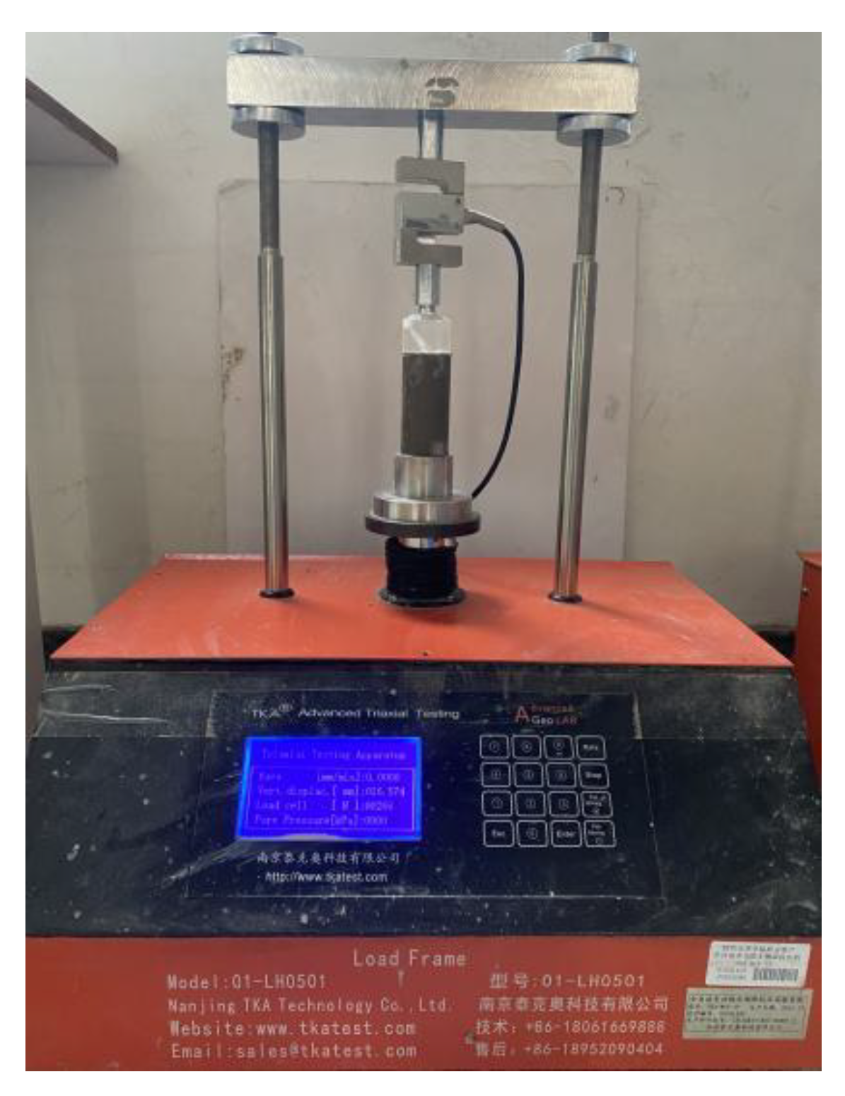
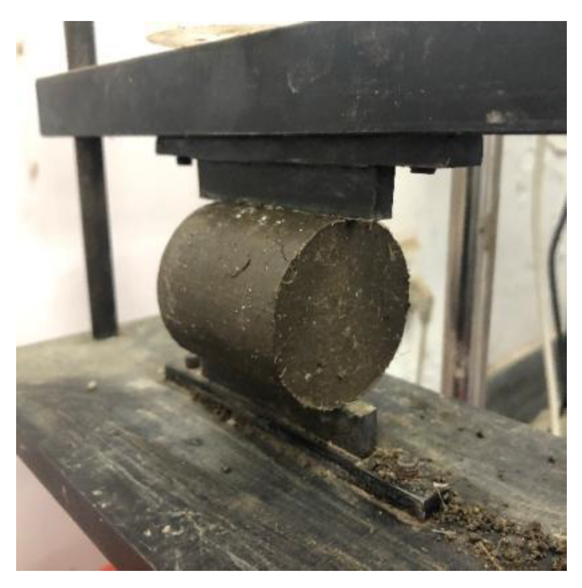
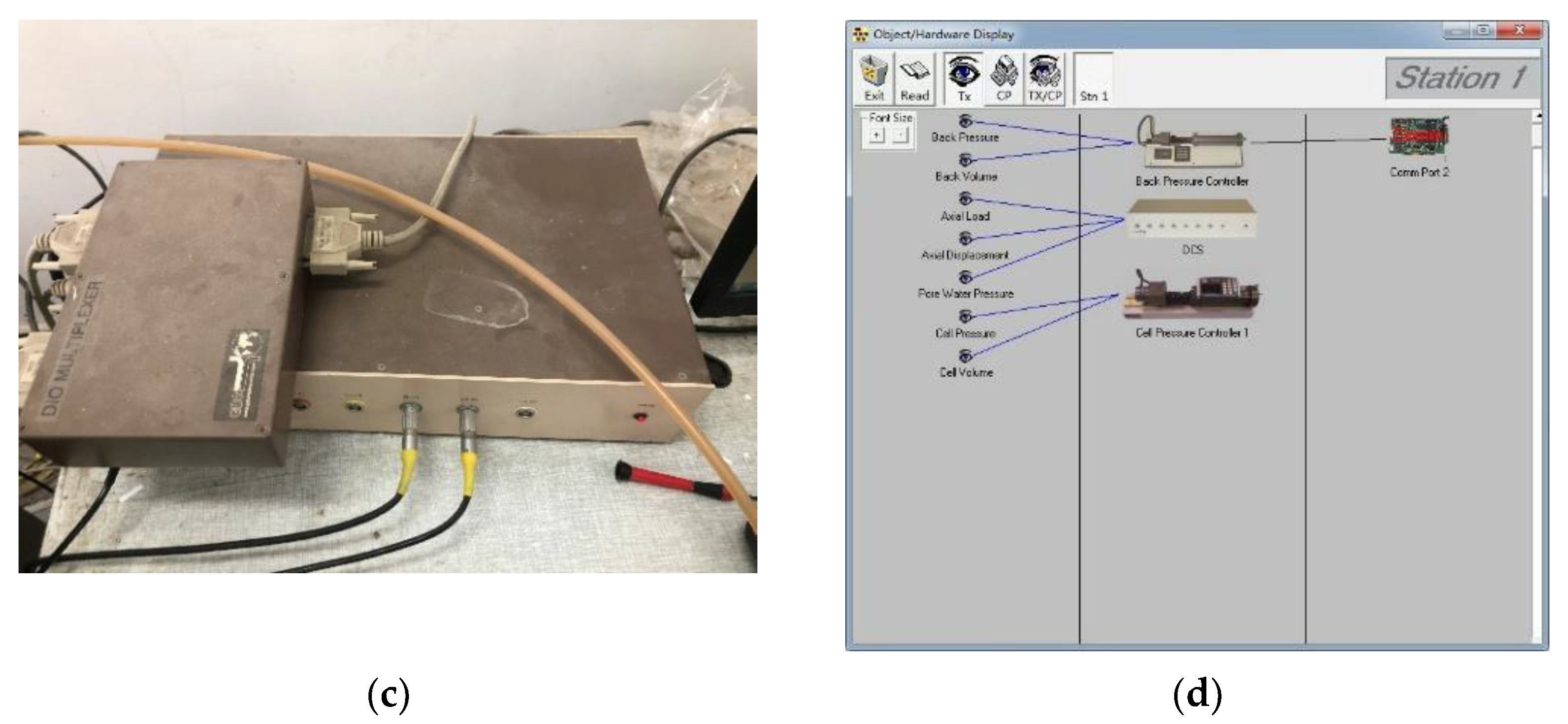
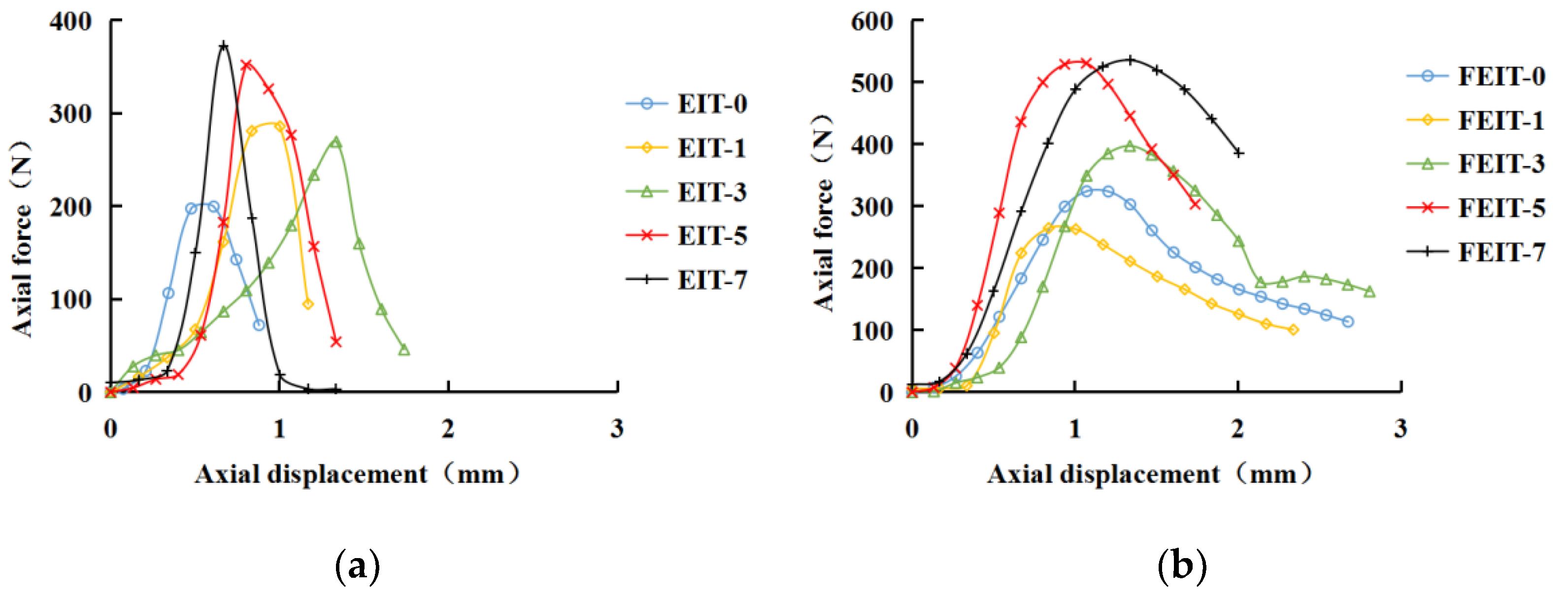
2.4.3. Dynamic Triaxial Test

In practical engineering, as a subgrade material, FEIT will be affected by the dynamic traffic load; it is very important to study the dynamic characteristics of FEIT after dry–wet cycles. We conducted a dynamic triaxial test on EIT and FEIT after dry–wet cycles, and the confining pressures were 100 kPa, 200 kPa, 300 kPa and 400 kPa. The instrument used in the test was the dynamic triaxial instrument produced by GDS Company in the UK. The instrument is composed of six parts: triaxial pressure chamber, confining pressure controller, back pressure controller, data collector, power driver and control system, as shown in Figure 7. The displacement control method is adopted in the test. After debugging, the displacement is 0.05 mm, the frequency is 1 Hz [20], and the loading waveform is sinusoidal. The loading time axial stress curve is shown in Figure 8.
The dynamic characteristics of soil are mainly reflected in the dynamic elastic modulus Ed and damping ratio λ [21]. During the test, a hysteresis loop will be obtained for each load cycle, and the typical hysteresis loop is shown in Figure 9.
Dynamic elastic modulus Ed is the ratio of stress and strain of soil under a dynamic load, i.e., the slope of the connecting line at the top of each hysteretic cycle [22]. The calculation method is shown in Equation (2).
E d = σ d ε d
where Ed is the dynamic elastic modulus; σd is dynamic stress; εd is dynamic strain.
Damping refers to the characteristic that the amplitude of the vibration system decreases continuously due to the energy dissipation inside or outside the material under the dynamic load. Meanwhile, soil damping refers to the characteristic that the energy of the dynamic load is continuously dissipated under the internal friction of soil, which is equal to the ratio of the energy dissipated in each load cycle to the total energy generated by the dynamic load, which is commonly indicated by the damping ratio λ [23,24]. The greater the damping ratio, the greater the ability of the material to resist vibration attenuation. The common calculation method is shown in Equation (3).
λ = A 0 4 π A r
where λ is the damping ratio; A0 is the area wrapped by the hysteretic curve; Ar is the triangular area under the line from the origin to the maximum amplitude point, i.e., the triangle AOB, as shown in Figure 8.

3. Results and Discussions

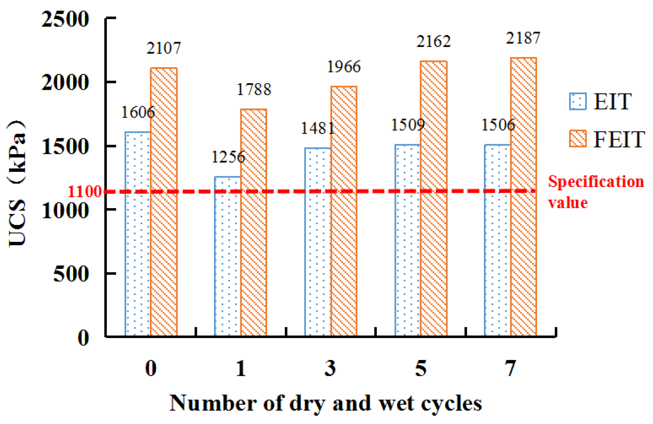
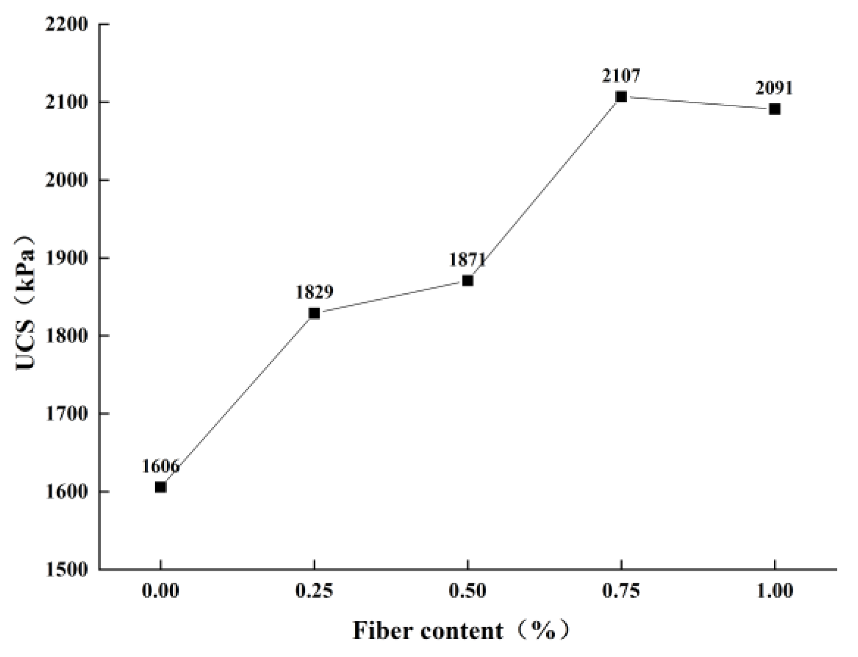
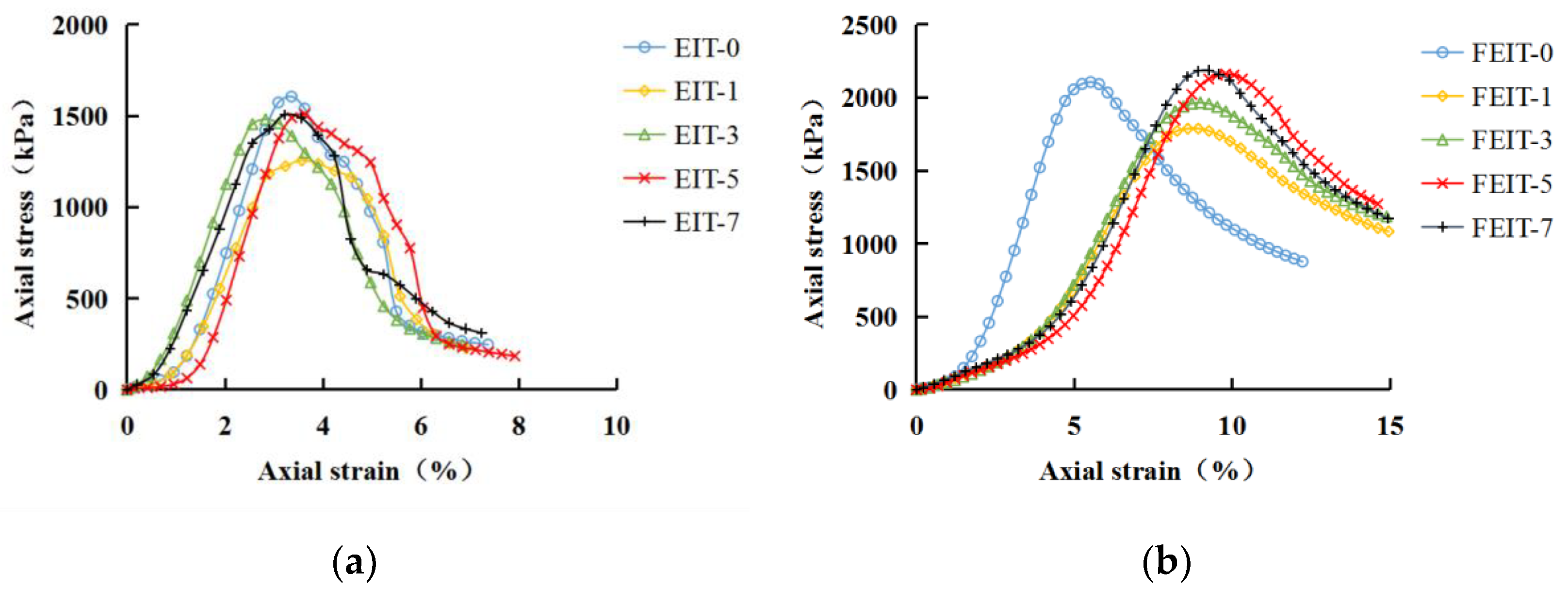
3.1. Effect of Dry–Wet Cycles on Unconfined Compressive Strength

The stress–strain curves of EIT and FEIT under axial load after dry–wet cycles are shown in Figure 10.
From Figure 10, the peak stress of EIT and FEIT is UCS, as shown in Figure 11.
It can be seen from Figure 11 that the UCS of EIT and FEIT changes similarly with the number of dry and wet cycles. After one dry and wet cycle, the UCS decreases, then gradually increases, and tends to be stable after the fifth dry and wet cycle. The decrease in UCS in the first dry–wet cycle is due to the development of wet expansion and shrinkage deformation in the sample after one dry–wet cycle of EIT, and the continuous expansion of micro-cracks in the sample [25,26], which will lead to the destruction of its own structure and the decrease in UCS. However, after several dry–wet cycles, UCS gradually increases to become stable. On the one hand, because the lime, fly ash and iron tailings have undergone sufficient ion exchange, crystallization and pozzolanic reaction [27], the generated cementitious material will form a chain connection structure and crystalline network structure inside the sample, so that the UCS will gradually improve, the final reaction will be completed, and the strength will be stable later. On the other hand, after several dry–wet cycles, the micro-cracks in the sample will expand to the limit degree and will not change. When the dry–wet cycle is experienced again, the damage caused by the deformation of wet expansion and dry shrinkage of its own structure will not develop, resulting in the stability of its strength [28].
Under different numbers of dry–wet cycles, the UCS of FEIT is always greater than EIT, because the bending mechanism and interleaving mechanism of fiber to soil can enhance the strength of soil [29]. At 0 dry–wet cycles, the UCS of FEIT was 31.2% higher than that of EIT. In the seventh dry–wet cycle, the UCS of FEIT was 45.2% higher than that of EIT. This shows that the dry–wet cycles can promote the UCS of FEIT.
According to the Chinese technical rules for construction of highway pavement base (JTGT F20-2015) [17], the unconfined compressive strength standard of lime and fly ash-stabilized material at the curing age of 7 days is ≥1.1 MPa. The early dry–wet cycle has a certain impact on this, while the strength of EIT and FEIT after the dry–wet cycle is 1.5 MPa and 2.1 MPa, respectively, which meets the requirements of the specification. According to the strength analysis of different solidified soils under dry–wet cycles by the following scholars, as shown in Table 7, the strength of FEIT obtained in this study is essentially better than other solidified soils after multiple dry–wet cycles. It shows that EIT and FEIT have good dry–wet cycle resistance.

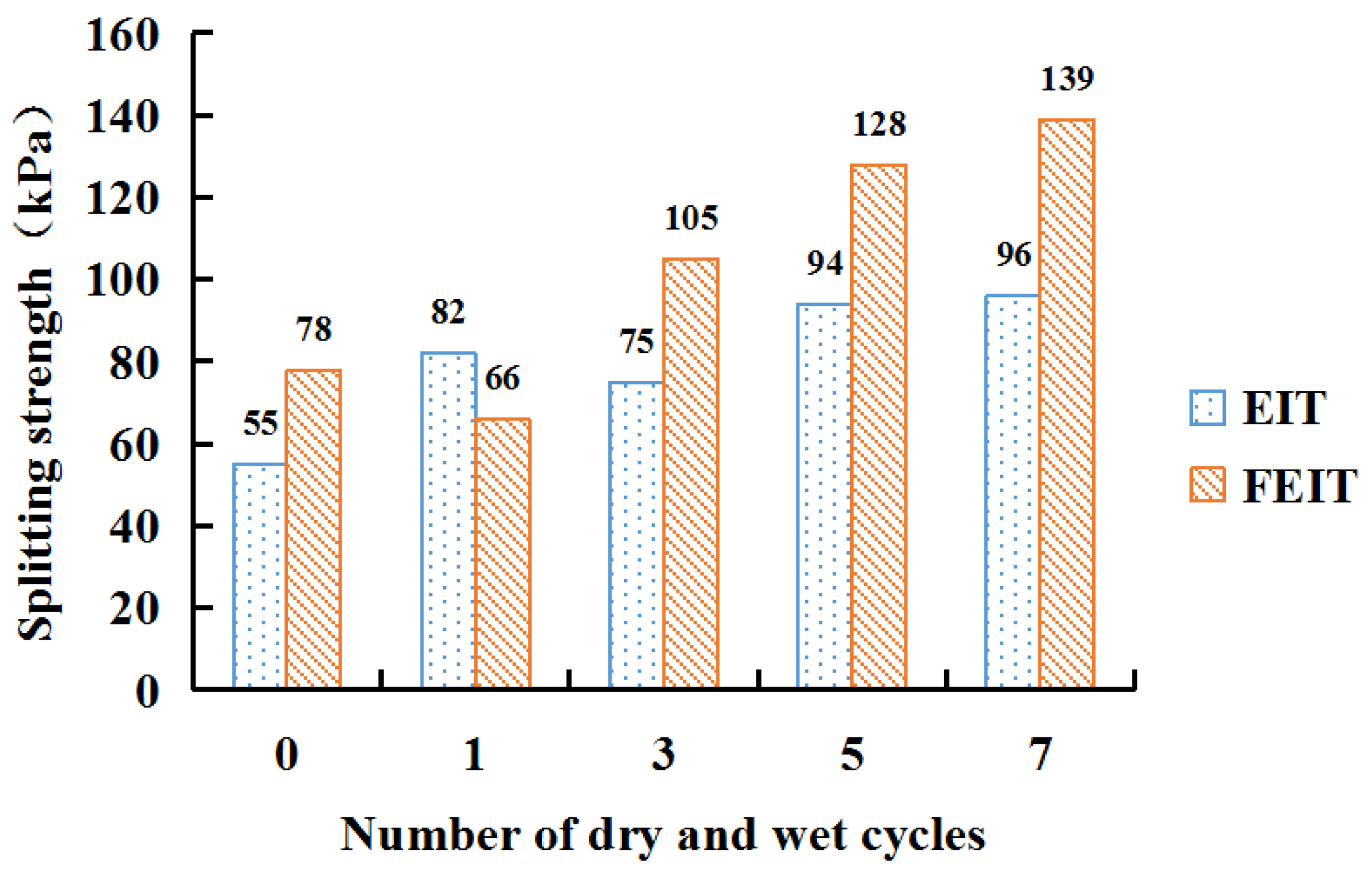
3.2. Effect of Dry–Wet Cycles on Splitting Compressive Strength

The splitting tensile force and displacement curves of EIT and FEIT after dry–wet cycles are shown in Figure 12.
The peak force can be obtained from Figure 12, and then the splitting tensile strength after different dry–wet cycles can be calculated according to Equation (1), as shown in Figure 13.
It can be seen from Figure 13 that the splitting strength of EIT and FEIT generally increases with the number of dry and wet cycles. The splitting strength of EIT and FEIT after 7 dry and wet cycles is 74.5% and 78.2% higher than that of 0 dry and wet cycles, respectively. This is because, in the early curing stage, with the progress of dry–wet cycles, lime, fly ash and iron tailings undergo a series of ion exchange, crystallization and pozzolanic reactions to produce cementitious materials with good water stability and crystals to connect with iron tailings, to improve the splitting strength of EIT and FEIT.
During the dry–wet cycles, the tensile strength of FEIT is better than that of EIT, which is due to the bite action between the fiber and iron tailing particles [34]. During the splitting test, the fiber in the fracture surface of the sample is gradually pulled out, and the fiber rubs with the iron tailing particles, resulting in the tensile strength of FEIT being greater than that of EIT. At 0 dry–wet cycles, the splitting strength of FEIT is 41.8% higher than that of EIT. In the seventh dry–wet cycle, the splitting strength of FEIT is 44.8% higher than that of EIT. Compared with the UCS, the dry–wet cycles only play a small role in promoting the splitting strength of FEIT.

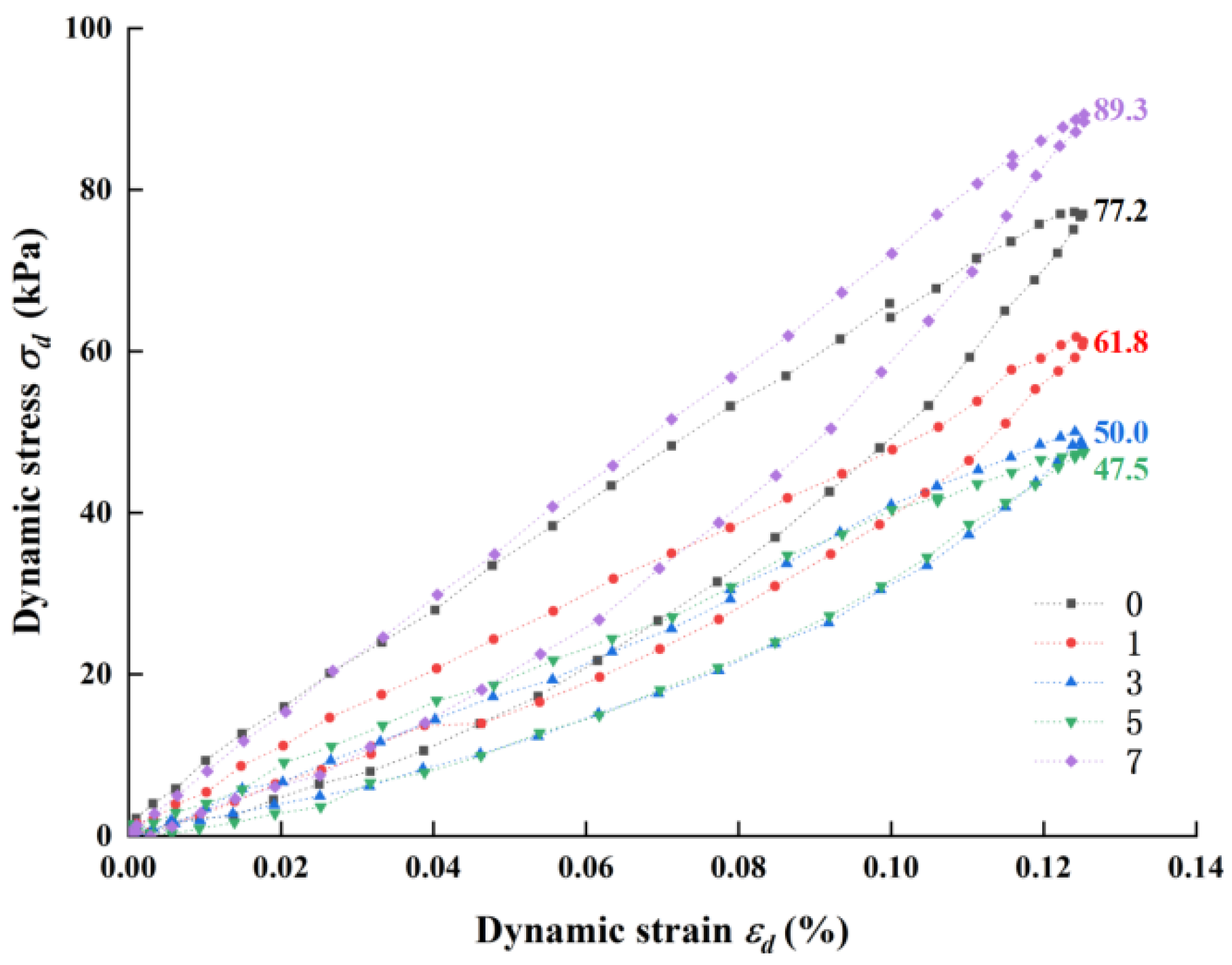
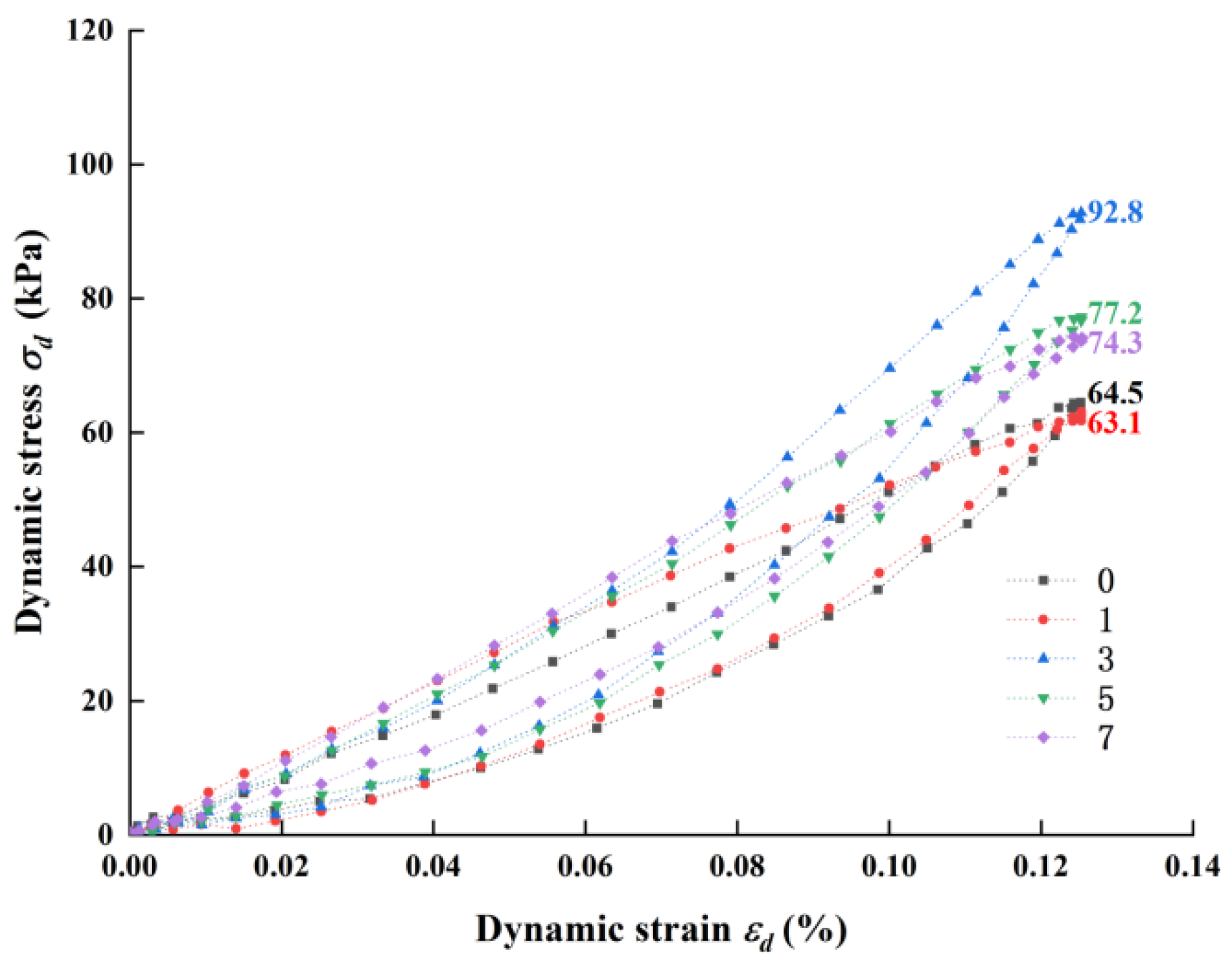
3.3. Influence of Dry–Wet Cycles on Dynamic Characteristics

The dynamic triaxial test of EIT and FEIT under dry–wet cycles was carried out, and the dry–wet cycle hysteresis curve was obtained. Take the EIT and FEIT hysteresis curve with confining pressure of 100 kPa as an example, as shown in Figure 14 and Figure 15.
Under the condition of strain control, the peak strain will not change. The greater the height of the hysteretic curve, the greater the maximum dynamic stress and the smaller the dynamic strain required to reach the maximum dynamic stress. The inclination angle of the hysteretic curve can reflect the change in the dynamic elastic modulus of soil under cyclic load [35]. The larger the inclination angle of the hysteretic curve, the larger its dynamic elastic modulus.
It can be seen from Figure 14 that when the confining pressure is 100 kPa, the maximum dynamic stress of EIT first increases and then decreases with the increase in dry and wet cycles. After the third dry and wet cycle, the maximum dynamic stress reaches 92.8 kPa. After seven dry and wet cycles, the dynamic stress of EIT increases by 15.2% compared with zero dry and wet cycles. After the cyclic load is applied, the inclination angle of the hysteretic curve of EIT under different dry and wet cycles increases, i.e., the dynamic elastic modulus increases.
It can be seen from Figure 15 that when the confining pressure is 100 kPa, the dynamic stress of FEIT changes with the dry–wet cycles, which is opposite to EIT. The maximum dynamic stress of FEIT first decreases and then increases with the increase in the number of dry–wet cycles. After the seventh dry–wet cycle, the dynamic stress of FEIT reaches the maximum value of 89.3 kPa, which is 15.7% higher than that of zero dry–wet cycles. After the cyclic load is applied, the inclination angle of the hysteretic curve of FEIT under the action of different dry and wet cycles becomes larger, with the exception of the seventh dry and wet cycle.

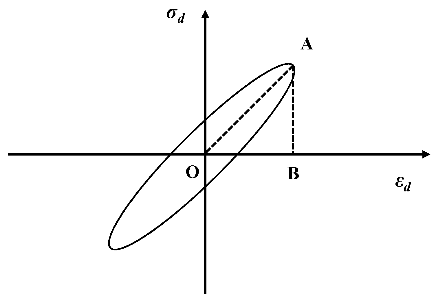
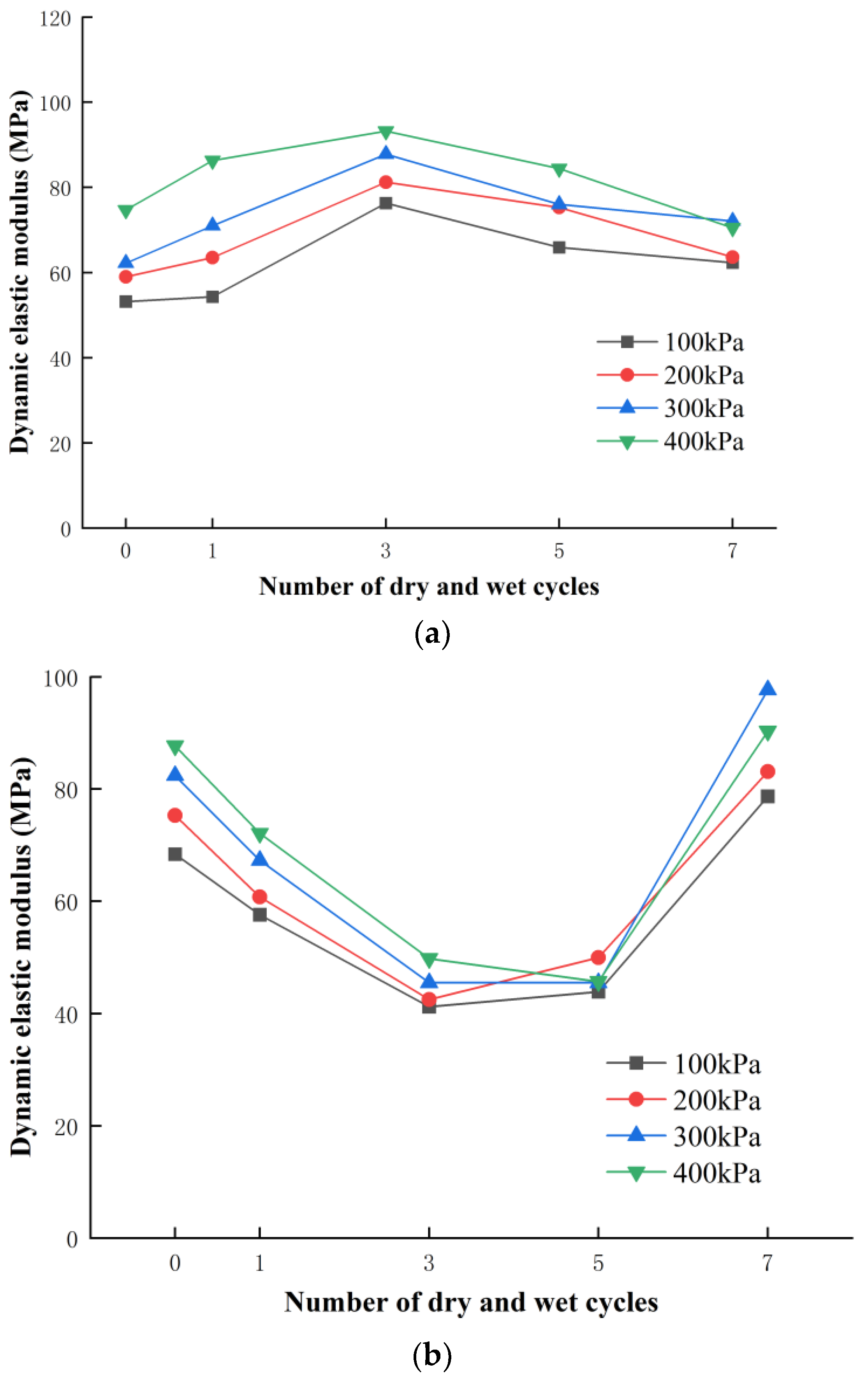
3.3.1. Effect of Dry–Wet Cycles on Dynamic Elastic Modulus Ed

According to the geometric properties of the hysteretic curve, the dynamic elastic modulus of EIT and FEIT under cyclic load can be obtained from Equation (2). The variation in the dynamic elastic modulus of EIT and FEIT with the number of dry and wet cycles under different confining pressures is shown in Figure 16.
As can be seen from Figure 15, (1) under the same confining pressure, the dynamic elastic modulus of EIT in different confining pressure environments shows a consistent law with the number of dry and wet cycles, i.e., the dynamic elastic modulus first increases and then decreases with the increase in the number of dry and wet cycles, indicating that the number of dry and wet cycles is the main factor affecting the change in dynamic elastic modulus. This is consistent with the conclusion that the variation in the dynamic elastic modulus is caused by the variation law of the inclination angle of the hysteretic loop. The reason for this trend is that in the early stage of dry–wet cycles, the quicklime in EIT absorbs sufficient water and produces sufficient Ca(OH)2, which accelerates the pozzolanic reaction of lime and fly ash. At this time, the hydration reaction is greater than the wet expansion of dry–wet cycles, resulting in the destruction of micro-cracks in the internal structure of EIT, and the strength of EIT is improved, to improve the dynamic elastic modulus. As the number of dry–wet cycles gradually increases, the hydration reaction inside the sample is complete. At this time, the damage damaging effect of dry–wet cycles on the EIT is greater than that of the hydration reaction. The internal micro-cracks of the sample are compressed, resulting in an increase in axial displacement and a decrease in the dynamic elastic modulus.
(2) Under the same confining pressure, the dynamic elastic modulus of FEIT in different confining pressure environments also has a consistent law with the number of dry and wet cycles, but contrary to EIT, the dynamic elastic modulus of FEIT first decreases and then increases with the increase in the number of dry and wet cycles. We recorded the weight of the sample after 0, 1, 3, 5 and 7 dry–wet cycles (soaking for 12 h and weighing after air drying for 12 h). The change in the sample weight of EIT and FEIT after dry–wet cycles is shown in Figure 17. It can be seen that the sample weight of FEIT is greater than that of EIT after dry–wet cycles. Because the fiber has water absorption, FEIT absorbs more water than EIT. At this time, the damaging effect of water on the interior of EIT is greater than the hydration reaction of lime fly ash, so the strength of FEIT decreases, resulting in a decrease in its dynamic elastic modulus. As the number of dry and wet cycles gradually increases, due to the good water retention of the fiber, the water has been locked in the interior of the EIT. At this time, the hydration reaction plays a greater role than the damage of water to the internal structure of the EIT. As mentioned above, the dry and wet cycles can promote the increase in the UCS of FEIT. Therefore, with the increase in the number of dry and wet cycles, the internal strength of FEIT increases, and the dynamic elastic modulus increases.
(3) When the number of dry–wet cycles is constant, the dynamic elastic modulus of EIT and FEIT generally increases with the increase in confining pressure, which is consistent with Lu’s conclusion [36]. This is because, with the increase in confining pressure, the interior of the sample is closer, and the slip and dislocation between different particles are reduced, so the axial displacement is reduced and the dynamic elastic modulus is increased. After seven dry–wet cycles, the deformation resistance of FEIT is better than that of EIT. The effect of the fiber greatly reduces the development of strain and increases the dynamic elastic modulus of FEIT.

3.3.2. Effect of Dry–Wet Cycles on Damping Ratio λ

According to the geometric properties of the hysteretic curve, the variation diagram of the damping ratio λ of EIT and FEIT with the number of dry and wet cycles under different confining pressures can be obtained from Equation (3), as shown in Figure 18.
It can be seen from Figure 16 that the λ of EIT and FEIT decreases with the increase in dry and wet cycles and then tends to be stable. This is because, with the dry–wet cycles, the particles in the sample react to form cementitious substances and crystals, which are connected with the iron tailings, so that the interior of the sample is closer, the slip and dislocation between different particles are reduced, the friction between different particles is reduced, and the energy lost in the propagation of the stress wave is reduced, resulting in the reduction of λ. Finally, due to the complete internal reaction of the sample, it tends to be stable. After seven dry–wet cycles, the damping of FEIT is obviously lower than that of 0 dry–wet cycles, while the damping of EIT after seven dry–wet cycles is not obviously lower than that of 0 dry–wet cycles. It shows that the dry–wet cycles can promote the vibration resistance of fiber-reinforced fly ash iron tailings.
When the number of dry–wet cycles is constant, the λ of EIT or FEIT is generally lower than that of low confining pressure at high confining pressure, which is consistent with the research conclusion of Wang [37]. This is because the smaller the confining pressure, the looser the overall skeleton of the sample, and the stress wave lingers and rotates in the pores and micro-cracks in the loose skeleton many times before reaching the next stage. During this period, a lot of energy will be lost, so the λ of low confining pressure is larger as a whole. It can also be seen from Figure 16 that the λ of FEIT, marked in red, is generally greater than the λ of EIT, marked in black. This is because, during the test, the mixing energy of the fiber absorbs a certain amount of energy, resulting in the increase in the energy lost during the propagation of the stress wave and the increase in the damping ratio [38].

4. Conclusions

Through an unconfined compressive strength test, splitting tensile strength test and dynamic triaxial test, the static and dynamic characteristics of EIT and FEIT under different numbers of dry–wet cycles at an early curing age were studied. The following conclusions can be obtained.
(1)
The UCS of EIT and FEIT decreased after a dry–wet cycle, and then gradually increased and stabilized. Under different dry–wet cycles, the UCS of FEIT is greater than that of EIT, and the dry–wet cycles promote the UCS of FEIT.
(2)
The splitting strength of EIT and FEIT increased with the number of dry–wet cycles. The tensile strength of FEIT is better than that of EIT, and the dry–wet cycles only play a small role in promoting the splitting strength of FEIT.
(3)
The dynamic stress of EIT and FEIT increased after seven dry–wet cycles. The dry–wet cycle is the main factor affecting the change in the dynamic elastic modulus of EIT and FEIT. Under the same confining pressure, the dynamic elastic modulus of EIT first increases and then decreases with the increase in dry–wet cycle times. On the contrary, the dynamic elastic modulus of FEIT first decreases and then increases with the increase in dry–wet cycle times. After seven dry–wet cycles, FEIT has better resistance to dynamic load deformation than EIT. The damping ratio of EIT and FEIT decreases with the increase in dry–wet cycles, and then tends to be stable. The damping ratio of FEIT is greater than that of EIT, and the dry–wet cycles can promote the vibration resistance of FEIT.

Author Contributions

Formal analysis, N.L.; writing—review and editing, X.Z. and P.J.; investigation, J.Q.; conceptualization, N.L. All authors have read and agreed to the published version of the manuscript.

Funding

This research was funded by the Zhejiang Provincial Natural Science Foundation of China (Grant number LQ20E080042).

Institutional Review Board Statement

Not applicable.

Informed Consent Statement

Not applicable.

Data Availability Statement

Not applicable.

Conflicts of Interest

The authors declare no conflict of interest.

References

  1. Li, N.; Lv, S.; Wang, W.; Guo, J.; Jiang, P.; Liu, Y. Experimental investigations on the mechanical behavior of iron tailings powder with compound admixture of cement and nano-clay. Constr. Build. Mater. 2020, 254, 119259. [Google Scholar] [CrossRef]
  2. Chu, C.; Zhang, F.; Wu, D.; Zhan, M.; Liu, Y. Study on Mechanical Properties of the Expansive Soil Treated with Iron Tailings Sand. Adv. Civ. Eng. 2021, 2021, 9944845. [Google Scholar] [CrossRef]
  3. Zhang, Z.; Zhang, Z.; Yin, S.; Yu, L.A.-O. Utilization of Iron Tailings Sand as an Environmentally Friendly Alternative to Natural River Sand in High-Strength Concrete: Shrinkage Characterization and Mitigation Strategies. Materials 2020, 13, 5614. [Google Scholar] [CrossRef] [PubMed]
  4. Hu, L.; Wu, H.; Zhang, L.; Zhang, P.; Wen, Q. Geotechnical Properties of Mine Tailings. J. Mater. Civ. Eng. 2017, 29, 4016220. [Google Scholar] [CrossRef]
  5. Stoltz, G.; Cuisinier, O.; Masrouri, F. Weathering of a lime-treated clayey soil by drying and wetting cycles. Eng. Geol. 2014, 181, 281–289. [Google Scholar] [CrossRef]
  6. Ying, Z.; Cui, Y.-J.; Benahmed, N.; Duc, M. Changes of small strain shear modulus and microstructure for a lime-treated silt subjected to wetting-drying cycles. Eng. Geol. 2021, 293, 106334. [Google Scholar] [CrossRef]
  7. Wu, Y.; Shi, K.; Han, Y.; Han, T.; Yu, J.; Li, D. Experimental Study on Strength Characteristics of Expansive Soil Improved by Steel Slag Powder and Cement Under Dry–Wet Cycles. Iran. J. Sci. Technol. Trans. Civ. Eng. 2021, 45, 941–952. [Google Scholar] [CrossRef]
  8. Xu, J.; Ren, C.; Wang, S.; Gao, J.; Zhou, X. Permeability and Microstructure of a Saline Intact Loess after Dry-Wet Cycles. Adv. Civ. Eng. 2021, 2021, 6653697. [Google Scholar] [CrossRef]
  9. Ziaie moayed, R.; Alibolandi, M.; Lahiji, B. Impacts of freezing-thawing and wetting-drying cycles on a silt stabilized by lime and waste silica. Environ. Eng. Manag. J. 2018, 17, 2905–2913. [Google Scholar] [CrossRef]
  10. Atma, P.; Sanandam, B.; Budhaditya, H.; Ankit, G.; Sekharan, S.; Qinhua, W. Probabilistic analysis of soil suction and cracking in fibre-reinforced soil under drying–wetting cycles in India. Environ. Geotech. 2019, 6, 188–203. [Google Scholar]
  11. Kamaruddin, F.A.; Anggraini, V.; Kim Huat, B.; Nahazanan, H. Wetting/Drying Behavior of Lime and Alkaline Activation Stabilized Marine Clay Reinforced with Modified Coir Fiber. Materials 2020, 13, 2753. [Google Scholar] [CrossRef] [PubMed]
  12. Wang, T.; Hao, Y.; Wang, Z.; Cheng, L.; Li, J. Experimental study on dynamic strength properties of compacted loess under wetting-drying cycles. Chin. J. Rock Mech. Geotech. Eng. 2020, 39, 1242–1251. (In Chinese) [Google Scholar]
  13. Hu, Z.; Ai, P.; Li, Z.; Ma, Q.; Li, L. Experimental study on dynamic strength properties of compacted loess under wetting-drying cycles. Rock Soil Mech. 2021, 42, 2722–2732. (In Chinese) [Google Scholar]
  14. Jiang, P.; Chen, Y.; Wang, W.; Yang, J.; Wang, H.; Li, N.; Wang, W. Flexural behavior evaluation and energy dissipation mechanisms of modified iron tailings powder incorporating cement and fibers subjected to freeze-thaw cycles. J. Clean. Prod. 2022, 351, 131527. [Google Scholar] [CrossRef]
  15. JTG3430-2020 Test Methods of Soils for Highway Engineering; China Communications Press: Beijing, China, 2020. (In Chinese)
  16. Bai, W.; Kong, L.; Guo, A. Effects of physical properties on electrical conductivity of compacted lateritic soil. J. Rock Mech. Geotech. Eng. 2013, 5, 406–411. [Google Scholar] [CrossRef] [Green Version]
  17. JTG/T F20-2015 Construction Guidelines for Highway Basw and Subbase; China Communications Press: Beijing, China, 2015. (In Chinese)
  18. JTG E51–2009 Test Methods of Materials Stabilized with Inorganic Binders for Highway Engineering; China Communications Press: Beijing, China, 2009. (In Chinese)
  19. Wang, W.; Liu, J.; Li, N.; Ma, L. Mechanical properties and micro mechanism of Nano-SiO2 modified coastal cement soil at short age. Acta Mater. Compos. Sin. 2021, 39, 1706–1719. (In Chinese) [Google Scholar] [CrossRef]
  20. Du, J.; Liu, B.; Wang, Z.; Zheng, G.; Jiang, N.-J.; Zhou, M.; Zhou, H. Dynamic behavior of cement-stabilized organic-matter-disseminated sand under cyclic triaxial condition. Soil Dyn. Earthq. Eng. 2021, 147, 106777. [Google Scholar] [CrossRef]
  21. Zhang, J.; Cao, J.; Huang, S.; Shi, B. Experimental study on the dynamic shear modulus and damping ratio of saturated sand under cyclic loading. Mater. Technol. 2021, 55, 741–749. [Google Scholar] [CrossRef]
  22. Chen, Z.; Xu, H.; Cheng, M.; Lu, H.; Wang, Z.; Feng, P. Dynamic Triaxial Test and Microscopic Study of Solidified Muddy Soil With Different Mixing Ratios and Curing Ages. Front. Mater. 2021, 8, 326. [Google Scholar] [CrossRef]
  23. Wang, R.; Hu, Z.; Ren, X.; Li, F.; Zhang, F. Dynamic modulus and damping ratio of compacted loess under long-term traffic loading. Road Mater. Pavement Des. 2021, 1–15. [Google Scholar] [CrossRef]
  24. Liu, F.; Zhou, Z.; Ma, W.; Zhang, S.; Sun, Z. Dynamic Parameters and Hysteresis Loop Characteristics of Frozen Silt Clay under Different Cyclic Stress Paths. Adv. Mater. Sci. Eng. 2021, 2021, 3763181. [Google Scholar] [CrossRef]
  25. Tang, C.-S.; Wang, D.-Y.; Zhu, C.; Zhou, Q.-Y.; Xu, S.-K.; Shi, B. Characterizing drying-induced clayey soil desiccation cracking process using electrical resistivity method. Appl. Clay Sci. 2018, 152, 101–112. [Google Scholar] [CrossRef]
  26. Hu, Z.; Peng, K.; Li, L.; Ma, Q.; Xiao, H.; Li, Z.; Ai, P. Effect of Wetting-Drying Cycles on Mechanical Behaviour and Electrical Resistivity of Unsaturated Subgrade Soil. Adv. Civ. Eng. 2019, 2019, 3465327. [Google Scholar] [CrossRef]
  27. Zhao, G.; Yan, H.; Yan, Y.; Gao, S.; Fan, D.; He, Y.; Wang, Y. Experimental study on the dynamic properties of lime-solidified soft soil under cyclic loading. Arab. J. Geosci. 2020, 13, 671. [Google Scholar] [CrossRef]
  28. Zhang, D. Experimental Study of Strength Characteristics of Lime Stabilized Soil in Drying and Wetting Cycles. J. Shanghai Jiaotong Univ. 2011, 45, 128–132. (In Chinese) [Google Scholar]
  29. Zhang, Y.; Zhang, X.; Zhang, H. Test research of geotechnique textile soil reinforcement mechanism and engineering application. Rock Soil Mech. 2005, 26, 1323–1326. (In Chinese) [Google Scholar]
  30. Fakhrabadi, A.; Ghadakpour, M.; Choobbasti, A.J.; Kutanaei, S.S. Evaluating the durability, microstructure and mechanical properties of a clayey-sandy soil stabilized with copper slag-based geopolymer against wetting-drying cycles. Bull. Eng. Geol. Environ. 2021, 80, 5031–5051. [Google Scholar] [CrossRef]
  31. Jiang, Y.J.; Ni, C.Y.; Sha, H.W.; Li, Z.-H.; Cai, L.-Y. Deterioration characteristics of cement-improved loess under dry-wet and freeze-thaw cycles. PLoS ONE 2021, 16, e0253199. [Google Scholar] [CrossRef]
  32. Horpibulsuk, S.; Suksiripattanapong, C.; Samingthong, W.; Rachan, R.; Arulrajah, A. Durability against Wetting–Drying Cycles of Water Treatment Sludge–Fly Ash Geopolymer and Water Treatment Sludge–Cement and Silty Clay–Cement Systems. J. Mater. Civil Eng. 2015, 28, 04015078. [Google Scholar] [CrossRef]
  33. Ma, D.; Kong, S.; Li, Z.; Zhang, Q.; Wang, Z.; Zhou, Z. Effect of wetting-drying cycle on hydraulic and mechanical properties of cemented paste backfill of the recycled solid wastes. Chemosphere 2021, 282, 131163. [Google Scholar] [CrossRef]
  34. Zhang, Z.; Chen, S.; Ji, E.; Fu, Z. Tensile fracture properties of gravelly soil reinforced by polypropylene fiber. Rock Soil Mech. 2021, 42, 2713–2721. (In Chinese) [Google Scholar]
  35. Yu, S.; Qu, S.; Yang, L.; Zeng, Q.; Wang, H. Research on the Saturated Cohesive Soil with Strain Controlled Dynamic Triaxial Test. J. Railw. Enginee Ring Soc. 2019, 36, 24–28. (In Chinese) [Google Scholar]
  36. Lu, Z.; Zhao, Y.; Xian, S.; Yao, H. Experimental Study on Dynamic Resilient Modulus of Lime-Treated Expansive Soil. Adv. Mater. Sci. Eng. 2020, 2020, 3272681. [Google Scholar] [CrossRef] [Green Version]
  37. Wang, M.; Shan, Z.; Wang, Y.; Di, S. Dynamic elastic moduli and damping ratios of marine sediments at zhoushan daishan based on dynamic triaxial tests under strain control. Chin. J. Rock Mech. Geotech. Eng. 2014, 33, 1503–1512. (In Chinese) [Google Scholar]
  38. Abbaspour, M.; Narani, S.S.; Aflaki, E.; Nejad, F.M. Dynamic characteristics of a sandy subgrade reinforced by waste tire textile fibres. Int. J. Pavement Eng. 2020, 21, 1–16. [Google Scholar] [CrossRef]
Figure 1. XRD test results of iron tailings.
Crystals 12 00568 g001
Figure 2. Relation curve between water content and dry density of EIT.
Crystals 12 00568 g002
Figure 3. Unconfined compressive strength of FEIT with different fiber content.
Crystals 12 00568 g003
Figure 4. Sample preparation and curing process of FEIT.
Crystals 12 00568 g004
Figure 5. Fully automatic multi-functional unconfined compression instrument.
Crystals 12 00568 g005
Figure 6. Splitting test process.
Crystals 12 00568 g006
Figure 7. Dynamic triaxial tester. (a) Triaxial pressure chamber and power driver; (b) confining pressure and back pressure controller; (c) data acquisition system; (d) software control system.
Crystals 12 00568 g007aCrystals 12 00568 g007b
Figure 8. Curves of loading time and axial stress.
Crystals 12 00568 g008
Figure 9. Typical curve of dynamic triaxial test.
Crystals 12 00568 g009
Figure 10. Stress–strain curves under dry–wet cycle: (a) EIT; (b) FEIT.
Crystals 12 00568 g010
Figure 11. Graph of UCS of EIT and FEIT changing with number of dry–wet cycles.
Crystals 12 00568 g011
Figure 12. Force–displacement curves under dry–wet cycle: (a) EIT; (b) FEIT.
Crystals 12 00568 g012
Figure 13. Graph of splitting strength of EIT and FEIT changing with number of dry–wet cycles.
Crystals 12 00568 g013
Figure 14. Hysteretic curve of EIT under 100 confining pressures of different dry–wet cycles.
Crystals 12 00568 g014
Figure 15. Hysteretic curve of FEIT under 100 confining pressures of different dry–wet cycles.
Crystals 12 00568 g015
Figure 16. Graph of Ed changing with a number of dry–wet cycles: (a) EIT; (b) FEIT.
Crystals 12 00568 g016
Figure 17. Mass change diagram of EIT and FEIT after dry–wet cycle.
Crystals 12 00568 g017
Figure 18. Mass change diagram of EIT and FEIT after dry–wet cycle under different confining pressures.
Crystals 12 00568 g018
Table 1. The main chemical composition of lime.
ComponentCaOAl2O3Fe2O3MgOOther
Content (%)89.40.250.181.768.41
Table 2. The main chemical composition of fly ash.
ComponentCaOAl2O3Fe2O3SiO2Burn VectorOther
Content (%)8.8625.3112.4435.564.5213.31
Table 3. The main chemical composition of iron tailings.
ComponentFe2O3Al2O3SiO2CaOMgONb2O5K2OOther
Content (%)22.944.3121.1524.786.596.892.4510.89
Table 4. The main chemical composition of clay.
ComponentFe2O3Al2O3SiO2CaONb2O5K2OOther
Content (%)15.6313.4750.252.545.785.676.66
Table 5. The physical and mechanical parameters of fiber.
Fiber TypeDiameter (μm)Length (mm)Density (g/cm3)Tensile Strength (MPa)Elastic Modulus
(GPa)
Polypropylene fiber18~4860.91>350>3.85
Table 6. Dry–wet cycle test scheme.
NOCuring Age (d)Dry–Wet CyclesTest TypeLoading Rate/mm·min−1Confining Pressure/kPaNumber of Dynamic Load Cycles
EIT, FEIT70, 1, 3, 5, 7UCS test1
Splitting tensile test1
Dynamic triaxial test100, 200, 300, 4001000
Table 7. Comparison of UCS of different solidified soils after dry–wet cycles.
ScholarSoilCuring AgentComparison of UCS Strength
after 7 Dry–Wet Cycles/kPa
Alireza et al. [30]Clay/sandCopper slag (CS)<0.6 MPa
Jiang et al. [31]LoessCement1.04~1.48 MPa
Suksun et al. [32]Clay/siltFly ash + cement<2 MPa
Dan et al. [33]Red sandstoneCement + gypsum<3.5 MPa
Publisher’s Note: MDPI stays neutral with regard to jurisdictional claims in published maps and institutional affiliations.

