Abstract
This study presents a double-inverse-epsilon-shaped, triple-band epsilon-negative (ENG) metamaterial with two split ring resonators (SRRs). The proposed unit cell comprises a single slit two SRRs with two inverse-epsilon-shaped metal bits. Rogers RT6002, of dimension 10 × 10 × 1.524 mm3, is used as a substrate. An electromagnetic simulator CST microwave studio is used to investigate the effective medium parameters of the material. The proposed metamaterial shows three resonance peaks that are demarcated at the frequencies 2.38 GHz, 4.55 GHz and 9.42 GHz consecutively. The negative permittivity of the metamaterial is observed at the frequency ranges of 2.39–2.62 GHz, 4.55–4.80 GHz and 9.42–10.25 GHz. The goodness of the material was presented by the effective medium ratio (EMR) of the unit cell at 12.61. In addition, the simulated results are authenticated by using different electromagnetic simulators such as HFSS and ADS for the equivalent circuit model, which exhibits insignificant disparity. The anticipated scheme was finalised through some parametric analyses, together with configuration optimisation, different unit cell dimensions, several substrate materials, and altered electromagnetic (EM) field transmissions. The proposed triple band (S-, C- and X-bands) with negative permittivity (ε) metamaterial is practically used for numerous wireless uses, for instance, far distance radar communication, satellite communication bands and microwave communication.
1. Introduction
The materials that are found surrounding us from nature can attain positive permittivity (ε) and permeability (µ). Perversely, an artificial engineered structure that can achieve some exotic characteristics, which are not found in nature, is called a metamaterial (MM). When a metamaterial exhibits negative permittivity or negative permeability, then it is termed as a single-negative (SNG) metamaterial, and if attains both negatives, then it is named as a double-negative (DNG) metamaterial [1]. The characteristics of a metamaterial not only depend on its elements, but rather, it is quietly subjected to its configuration [2], i.e., dimension, pattern, etc. A theoretical metamaterial with negative permittivity (ε) and negative permeability (µ) called a double-negative (DNG) metamaterial or left-handed metamaterial (LHM) was introduced by Russian physicist Victor Veselago in 1968 [3]. Metamaterial researchers are fascinated by the metamaterials’ cloaking, absorbing, blocking or meandering for their exotic electromagnetic properties [4,5]. A metamaterial structure embossed metal element showed the effect of temperature with the thickness of the metal [6]. This metamaterial is used for sensitive microwave sensor. A Greek-key pattern metamaterial of dimension 10 × 10 mm2 was fabricated using Rogers RT5880 that showed triple peaks of frequencies 2.4 GHz, 3.5 GHz and 4 GHz [7]. In ref. [8], Afsar et al. presented an epsilon-negative modified hexagonal-resonator-shaped metamaterial with EMR 11.53. Numerical analysis showed triple band resonance that covered the S-, X- and Ku-bands. In 2018, an experimental 3D metamaterial was demonstrated by Smith et al. [9] based on thin wire assemblies with an SSR that showed LHM characteristics with wide bandwidth. For the advancement of technology, SNG metamaterials and LHM have great contributions. Metamaterials with synthetic dielectric substrates started to be used after the Second World War for microwave applications.
In 2020, Dalgac et al. [10] designed a rectangular SSR-shaped metamaterial based on sensor structure to detect the influence of humidity on concrete materials in open space. Another study presented an S-shaped metamaterial of EMR 4.8 [11]. This L-band metamaterial was dedicated to the application of microwave sensors. A substrate with a dimension of 12.5 × 10 × 1.5 mm3 that was synthesised using a nickel-aluminate with a concentration of 42% aluminum [12] was designed for microwave application with the X- and Ku-bands. Gua et al. proposed a metamaterial with negative permittivity (ENG) to enhance the horizontal gain of patch antenna [13]. In 2016, Liu et al. [14] proposed a dual- band metamaterial (5 × 5 mm2 in dimension) with a reformed circular electric resonator (RCER) with an EMR 5.45 covering frequency ranges from 9.70 GHz to 10.50 GHz and 15 GHz to 15.70 GHz. In another study, a three-layered wide metamaterial in the terahertz frequency was designed for heavy solar radiation absorption [15]. Metamaterials that reveal a vigorous localisation and boost of field may deliver novel tools to significantly enhance the sensitivity and tenacity of sensors. Abdolrazzaghi et al. designed an ultrasensitive microwave sensor to monitor the glucose in blood serum concentration [16]. Meanwhile, Kazemi et al. [17] recently introduced a reflective sensor that organises coupled split ring resonators as the front-end sensing element to be used in dielectric medium categorisation. It can used in dielectric medium categorisation. Meanwhile, a composite LR-handed based microfluidic sensor [18] exhibited resonance by surface capacitance and inductance.
On the other hand, an NRI metamaterial that was based on SRR with wire strips is a 2D array of repeated unit cells [19]. Moreover, Pendry et al. designed a non-natural magnetic metamaterial using different types of SRRs which were printed on the dielectric substrate [20]. An open-delta-shaped negative permittivity (ε-negative) MM based on a square ring resonator [21] indicated three resonance peaks at 4.32 GHz, 7.55 GHz and 9.76 GHz that covered the C- and X-bands. Meanwhile, in 2015, Liu et al. offered a tunable metamaterial comprising an SRR [22] used for sensing, filtering and cloaking. A triple-band metamaterial with a pie-shaped resonator centred with SSR (8 × 8 mm2 in dimension) covered the S-, C- and X-bands [23]. In a recent study, a polarization-dependent, circular-shaped, triple-band metamaterial was designed using a Rogers RT6002 substrate base MM (8 × 8 mm2 in dimension) resonated at 3.924 GHz, 7.254 GHz and 14.832 GHz [24]. To enhance the antenna gain for satellite communication, a Minkowski-fractal-shaped metamaterial was discussed in another study [25]. The triple-band metamaterial designed with two circular rings and one rectangular SRR exhibited a two-resonance frequency of 2.56 GHz and 5.6 GHz, which was used for Wi-MAX and WLAN networking [26]. Additionally, Reddy et al. [27] in 2020 proposed a penta band based on complementary OSRR, which combined five resonance peaks that were suitable for Wi-MAX, WLAN, Satellite band and X-band applications. Meanwhile, H. Sakli et al. [28] proposed a new two-element, ultra-wideband (UWB) MIMO antenna to yield the miniaturisation and performance using two antennas and ensure proper operation of the multiple-input–multiple-output system.
This study offered a compact and innovative metamaterial muster whose unit cell comprised two SRRs with double inverse-epsilon-formed metal strips. This design established three resonance frequencies covering the S-, C- and X-bands (2–4 GHz, 4–8 GHz and 8–12 GHz) in the microwave spectra, in addition to an indication of the epsilon-negative and negative refractive indices (n) at the same frequencies. Moreover, for the consistency of its performance, the numerical results were verified by using different validation processes. The results attained from the HFSS and from the equivalent circuits designed by ADS were used to compare with the CST simulated results. Different important parameters, including permittivity (ε), permeability (µ) and refractive index (n), along with S11 and S21, were analysed to characterise the metamaterial. To compare the performance, the EMR-based table was discussed in the results segment. The doubleinverse-epsilon-shaped SRR-based metamaterial designed in this study was very much compact because a << λ/4 [for 2.38 GHz λ/4 = 31.51 mm, whereas size a = 10 mm]. This design produces three resonance peaks at 2.38 GHz, 4.55 GHz and 9.42 GHz with −29.40 dB, −39.65 dB and −43.35 dB, respectively. The EMR indicated the goodness of the unit cell material at 12.61.
2. Schematic Description of Unit Cell and Simulation
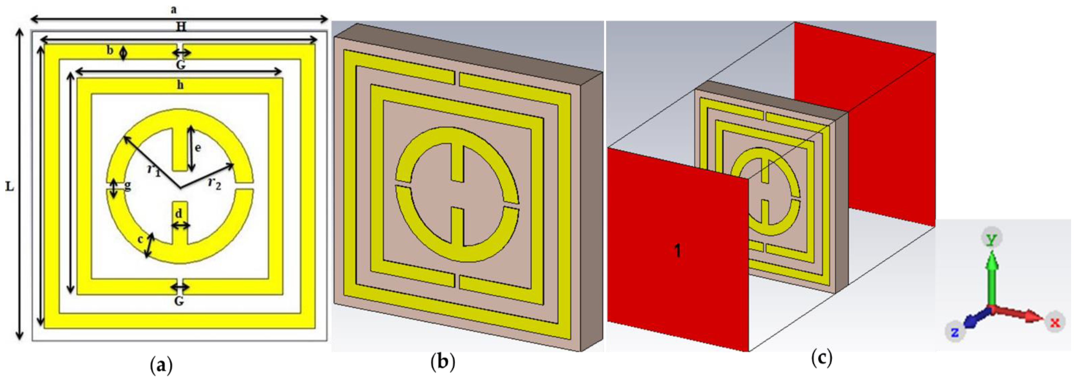
The parametric description of the proposed unit cell demonstrated in Figure 1a is a new arrangement of two square ring resonators with double-epsilon-shaped metal strips. Figure 1b illustrates the perspective view of the unit cell while Figure 1c shows the simulation setup.

Figure 1.
(a) Unit cell, (b) perspective view of unit cell and (c) simulation set up.
A square-shaped dielectric Rogers RT6002 material with a thickness (t) of 1.524 mm was used as substrate. The dimensions of the substrate were 10 × 10 mm2 with a dielectric constant of 2.94 and a loss tangent of 0.0012. The dimensions of the outer and inner SRR were 4.6 × 4.6 mm2 and 3.5 × 3.5 mm2, respectively. Copper (annealed) of conductivity is 5.96 × 10⁷ Sm−1 was utilised for all resonators of the top and bottom layers. Split gaps (G) of the each SRR was 0.20 mm, whereas the thickness of the copper strips were 0.035 mm. The split gap between the two epsilon-shaped resonators was also maintained at 0.20 mm. All metal strips were of same width (b) 0.50 mm except the epsilon-shaped bar in the centre of the unit cell. The outer radius (r1) and the inner radius (r2) of both the epsilon-shaped metals are 2.5 mm and 1.9 mm, respectively. The width (c) of the epsilon-shaped metal was 0.60 mm, whereas the length of each middle arm of the epsilon shape (e) was 1.50 mm with a thickness (d) of 0.50 mm. Table 1 summarises all the parametric magnitudes and the dimensions.

Table 1.
Parametric description of the unit cell.
To achieve the expected results from the proposed unit cell an electromagnetic wave is incident to the Z-axis while perfect electric condition (PEC) and perfect magnetic condition (PEM) along the X-axis and Y-axis, consecutively.
Extraction Method of Effective Medium Parameters
CST microwave studio based on finite integration technique was used to differentiate the combined symmetrical erection and integration of arbitrary distribution of material and their physical characteristics. The frequency-domain solver with a tetrahedral mesh of CST was used to simulate the expected research.
As mentioned earlier, the PEC and PEM boundary conditions were applied along the X-axis and Y-axis, while the EM radiation was applied to the Z-axis to simulate the unit cell within the frequency range of 1 GHz to 12 GHz. Three vital material characteristics—permittivity (), permeability and refractive index (nr)—were derived through the Nicolson–Ross–Weir (NRW) technique [29] to realize the EM properties of the MMs. Popularly used MATLAB code is established in the context of Equations (1)–(5). After the execution, the attained results were verified with the CST results:
3. Parametric Studies
3.1. Design Procedure
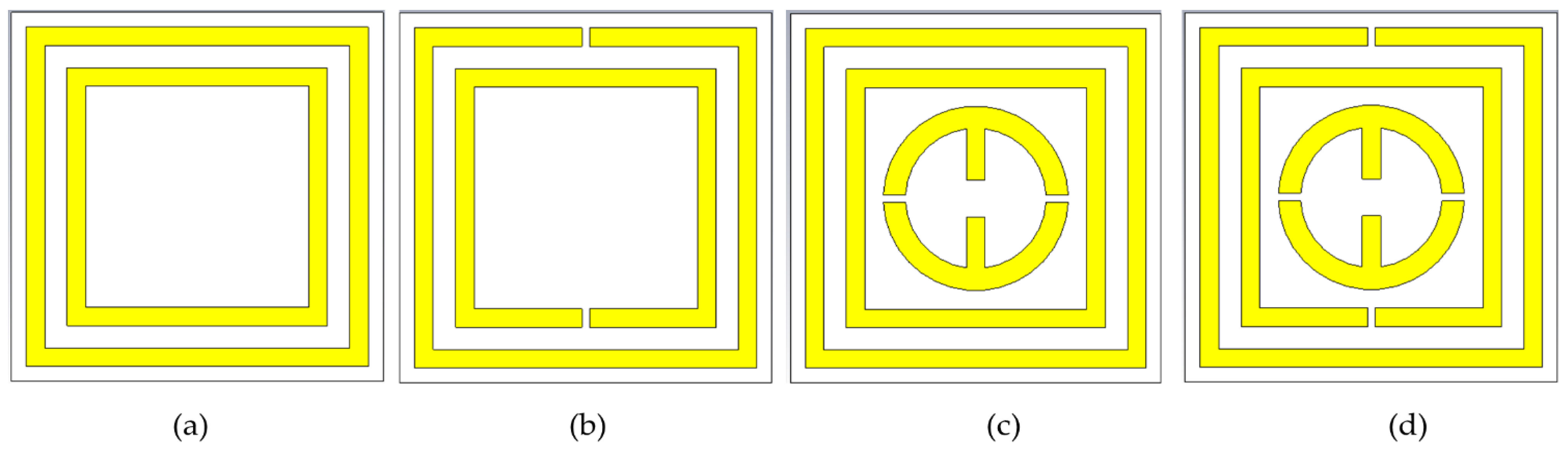
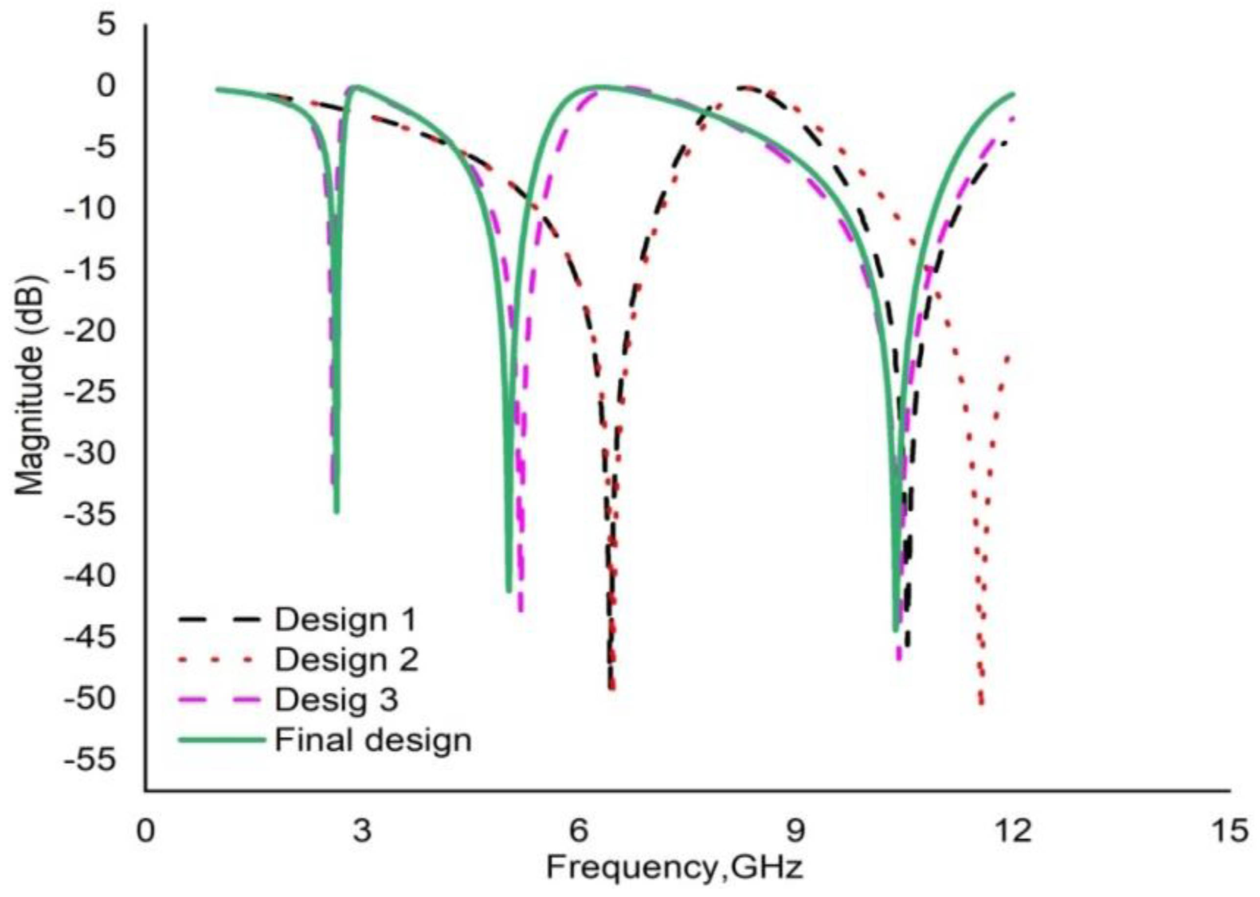
To achieve the desired goal, the prime design was selected from the trial designs to yield optimal performance. An iterative method was applied to assess the response of the unit cell. The length, width and distance between the SRRs together with the sizes of the slits were changed on a trial-and-error basis. Figure 2 depicts some of the trial designs. Figure 2a contains two square rings with a uniform width of 0.50 mm. The dimension of the outer and inner square ring is 9.2 × 9.2 × 0.035 mm3. Following the simulation, 2 major response peaks at 5.92 GHz and 10.67 GHz were observed. Next, a split gap of 0.20 mm in each square ring was introduced into the design in Figure 2a to produce SRR. The design in Figure 2b yielded 3 resonance frequencies at 2.38 GHz, 4.72 GHz and 9.55 GHz for S21. Figure 2c illustrates the introduction of two epsilon-shaped metal strips into design 1. The outer and inner radii of each epsilon were 2.5 mm and 1.9 mm, respectively, with a width of 0.60 mm. This altered design exhibited two resonances at 5.82 and 9.60 GHz. The placement of the two-epsilon shaped metals inside the second design yielded an excellence response satisfying our desired frequency band by producing three resonance peaks at 2.38 GHz, 4.55 GHz and 9.42 GHz with good bandwidth. Therefore, the proposed design in Figure 2d was selected as our final structure. Table 2 summarises the numerical results of different steps of design optimisation. The proposed final structure exhibited three resonance frequencies with negative permittivity (ε) and negative index (n) simultaneously. The simulated results for the different designs are depicted in Figure 3.
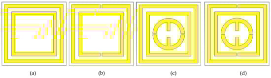
Figure 2.
Design optimisation view: (a) Design-1, (b) Design-2, (c) Design-3 and (d) proposed design.
Table 2.
Response of S21 for various designs.
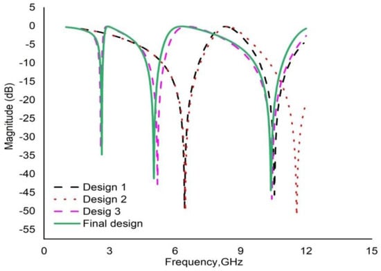
Figure 3.
Transmission coefficient (S21) for different design.
3.2. Unit Cell Size Optimisation
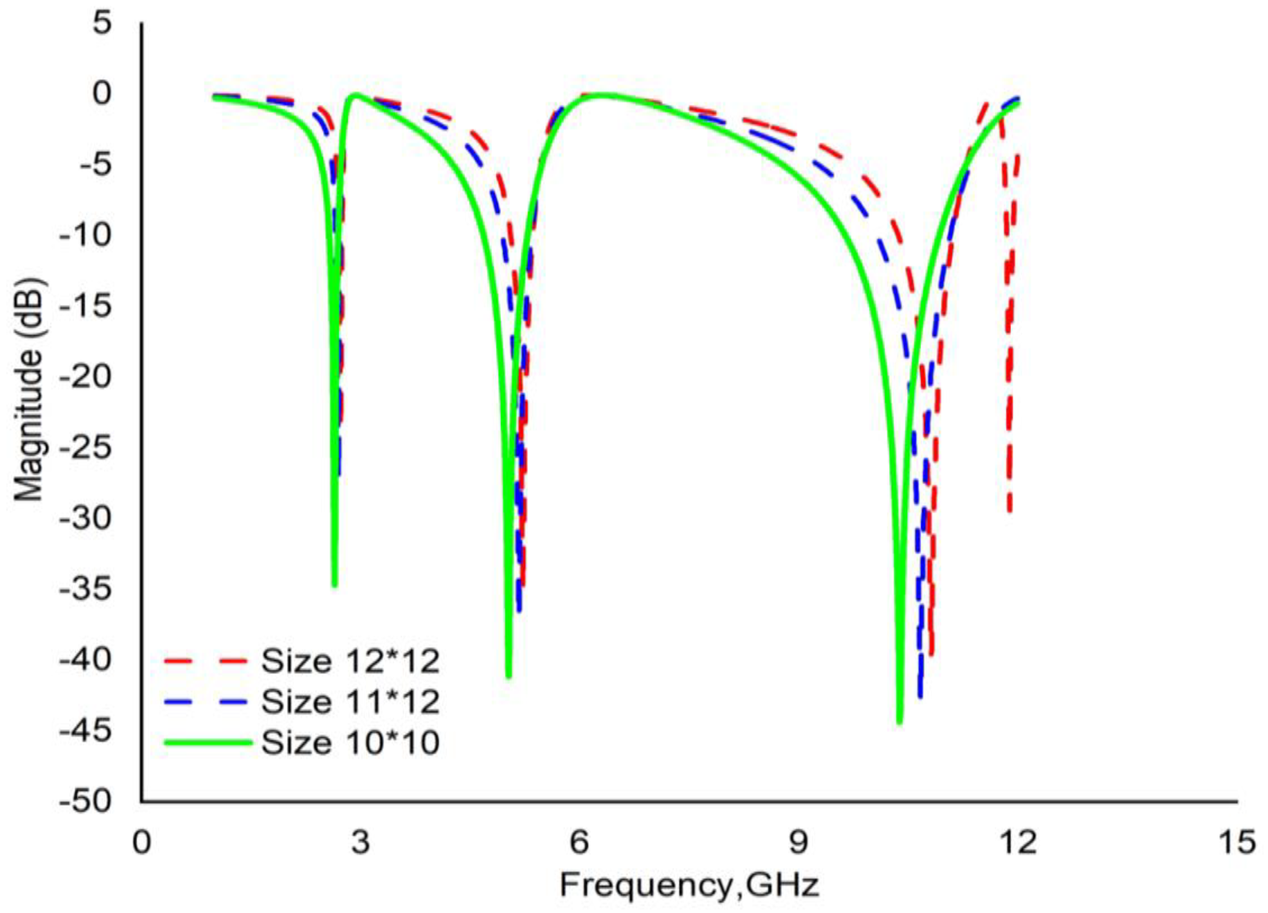
Different sizes of unit cell were also investigated to select the best dimension. The unit cell of three different sizes (10 mm, 11 mm and 12 mm) with the same thickness (1.524 mm) as the substrate (Rogers RT6002) were designed by keeping other components unaltered. The numerical results are demonstrated in Figure 4. It is evident from Figure 4 that the sizes of 11 mm and 12 mm exhibited 3 resonances at nearly the same frequency with a lower bandwidth, which is quite low compared to the 10 mm unit cell. On the other hand, the 10 mm unit cell exhibited 3 major resonances at 2.38 GHz, 4.55 GHz and 9.42 GHz. Therefore, finally the 10 × 10 × 1.524 mm3 dimension was selected for the projected metamaterial unit cell.

Figure 4.
Transmission coefficient (S21) for different dimension of the unit cell.
3.3. Effect of Substrate Materials
An analysis is carried out to select the appropriate dielectric for the substrate of the metamaterial unit cell, which is shown in Figure 5. Two Rogers dielectrics, namely, RT 5880 and RT 6002, together with a flame-retardant dielectric FR4, were separately investigated to observe their responses. RT5880 and FR4 produced three resonance peaks with narrow bandwidths. Contrarily, Rogers RT6002 (dielectric constant 2.2 and loss tangent 0.0012) yielded tri-resonance peaks and adequate bandwidth covering the S-, C- and X-bands with higher EMR 12.61. Hence, the proposed unit cell was designed on Rogers RT6002 (lossy) substrate.
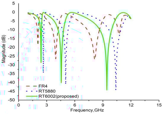
Figure 5.
Transmission coefficient (S21) for different substrate materials.
4. The Effect of Changing the Electromagnetic Field Propagation Direction
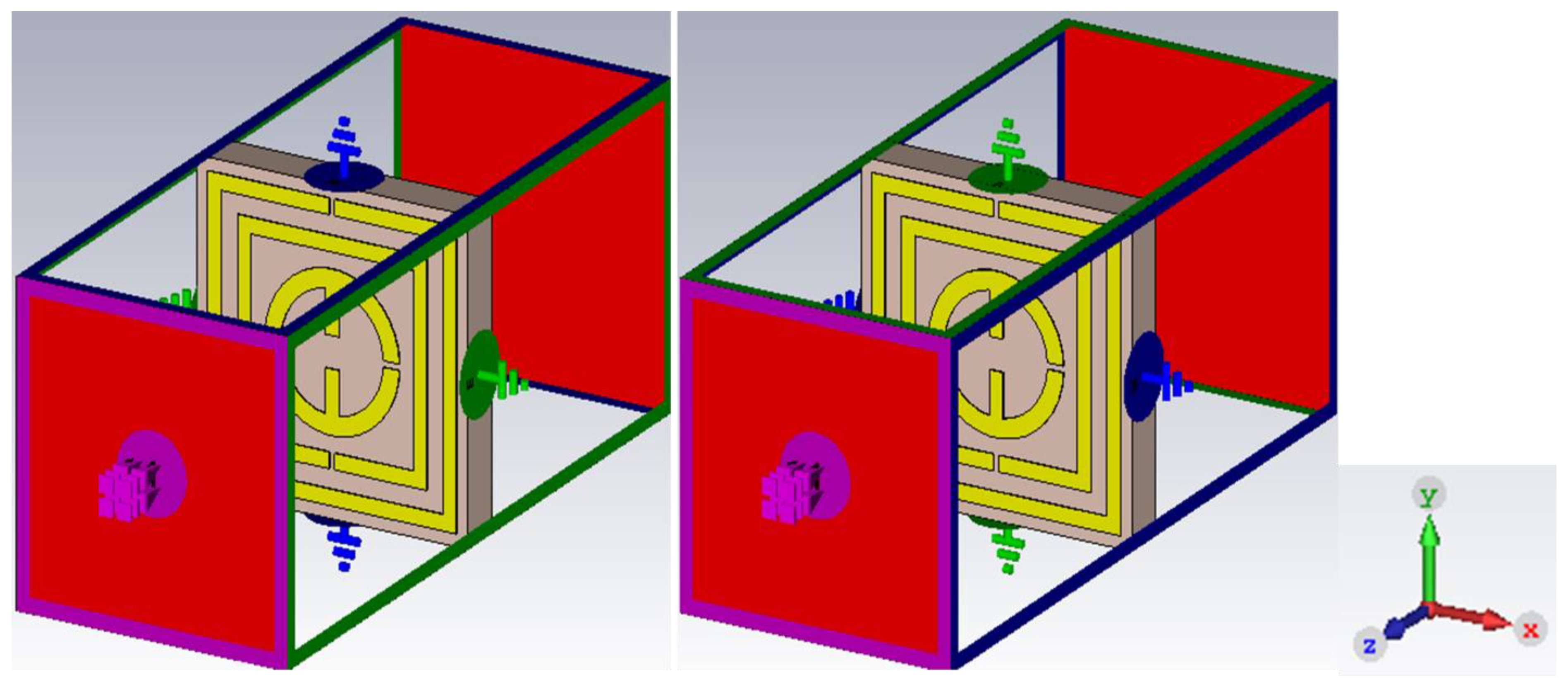
A regular technique was also employed to assess the effect of the changing transmission coefficient (S21) for varying field propagations. The simulation setup for the changed electric and magnetic fields is depicted in the Figure 6. The electric field (Ey) was applied along the Y-axis while the magnetic field (Hx) was applied along the X-axis. Two resonances that were recorded around 6 and 10 GHz.

Figure 6.
Simulation setup for changing field propagation.
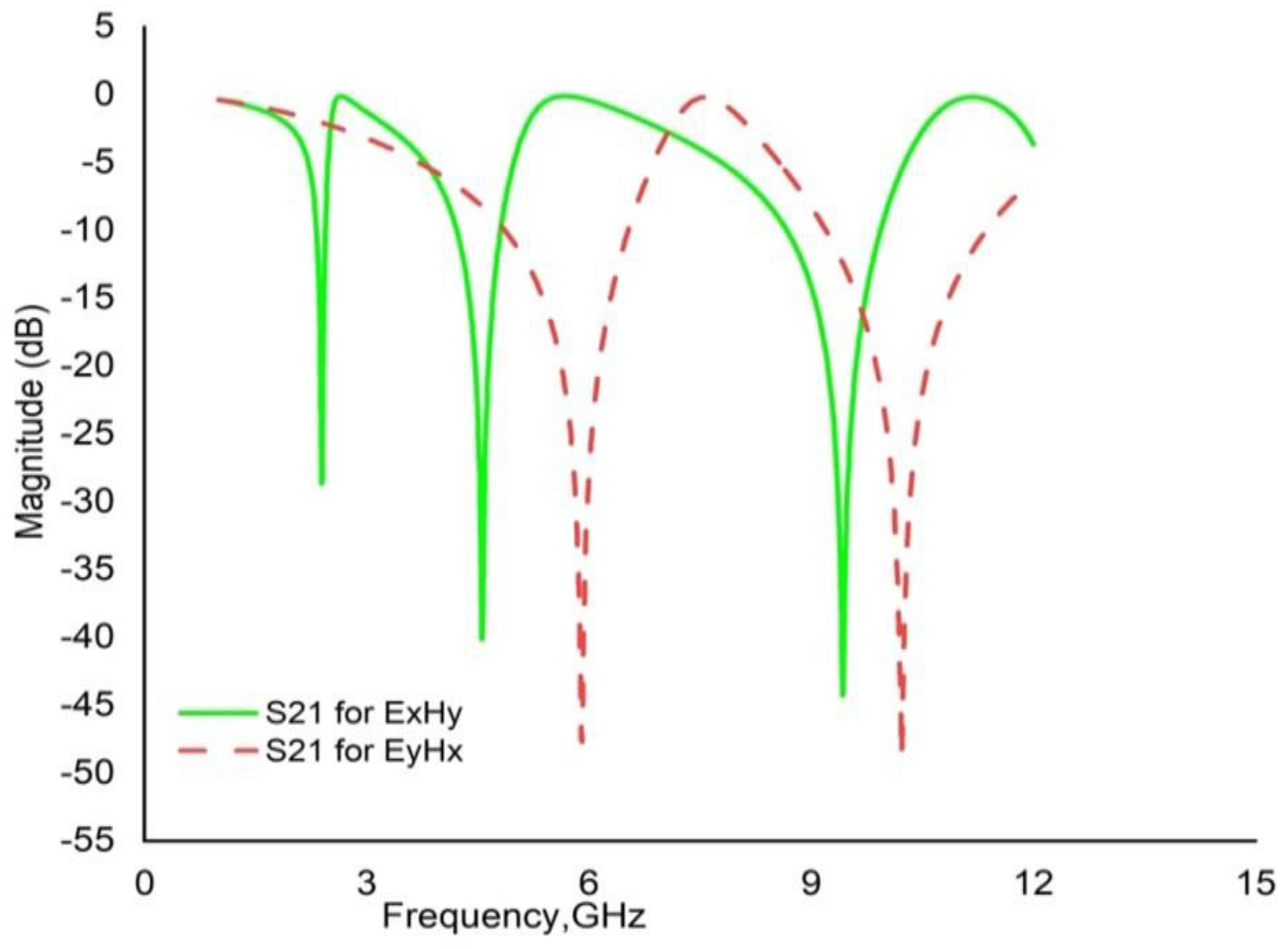
However, if the fields were interchanged with each other, i.e., the electric field (Ex) is applied towards the X-direction and the magnetic field (Hy) is applied towards the Y-direction, 3 major resonances would be observed at 2.38 GHz, 4.55 GHz and 9.42 GHz as depicted in Figure 7.

Figure 7.
Transmission coefficient (S21) for changing field direction.
5. Electromagnetic Fields and Surface Current Analysis
Ampere’s law of electromagnetic induction predicted that moving the charged particle can generate a magnetic field. According to Faraday’s laws of induction, the electromagnetic interface turns it into an electric field. The EM fields produced by time-varying charged particles can be expressed using Maxwell’s curl equation [30]:
where the operator is:
Equations (6) and (7) are insufficient to describe the correlation between the produced fields and the material. The following equations can be used to alleviate this drawback:
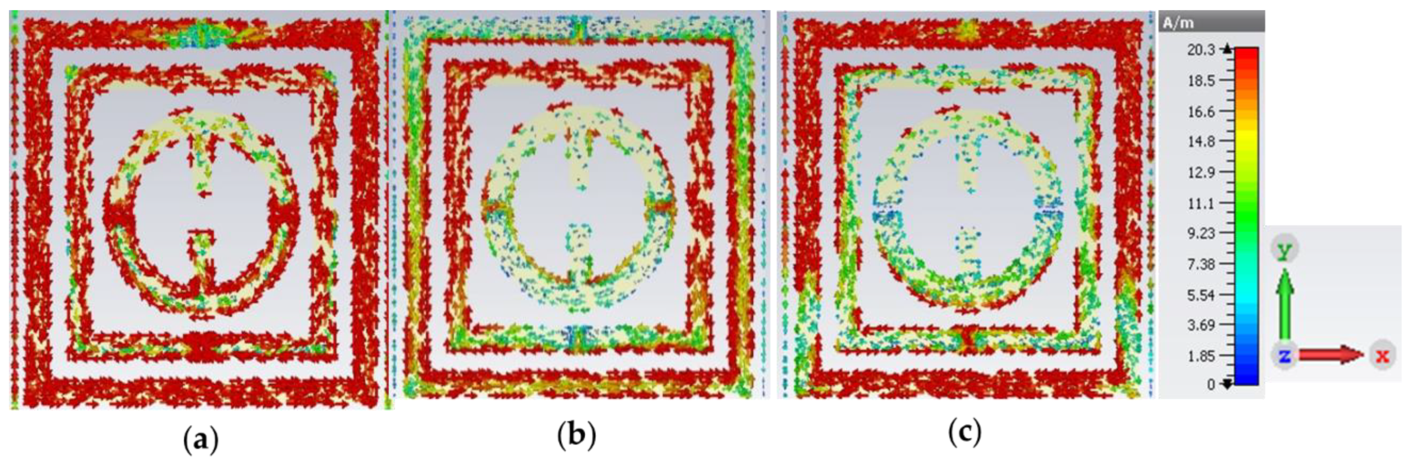
The three important features that can be described using the aforementioned equations include the electric field, magnetic field and surface current. Figure 8 and Figure 9 represent the electric field distribution and magnetic field distributions, respectively, for the 3 resonance frequencies of 2.38 GHz, 4.55 GHz and 9.42 GHz. The current flow changes with a change in frequency. Two SRRs of the unit cell are more influenced by surface current flow than the other resonators, which are depicted in Figure 10. Thus, it can be noted that the first 2 frequencies, 2.38 GHz and 4.55 GHz, belong to the 2 SRRs, whereas the two epsilon-shaped resonators, which are placed in the middle of the unit cell, produced a low current flow with a frequency of 9.42 GHz.
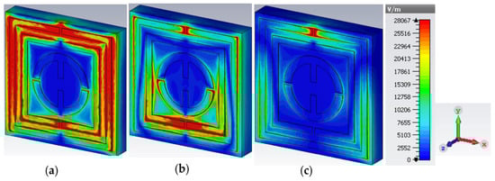
Figure 8.
Electric field distribution at (a) 2.38 GHz, (b) 4.55 GHz and (c) 9.42 GHz.

Figure 9.
Magnetic field distribution at (a) 2.38 GHz, (b) 4.55 GHz and (c) 9.42 GHz.
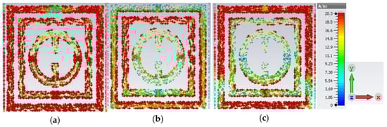
Figure 10.
Surface current at (a) 2.38 GHz, (b) 4.55 GHz and (c) 9.42 GHz.
The induced magnetic field intensity (B) depends on the current flow (I) or charge flow and the distance (r) of the conductor, which can be expressed using Biot–Savart’s law, [31], where is the permeability in free space. With the increase in the current flow, the strength of the magnetic field also increases. The same effect is also observed in the E field, as presented in Figure 8. When the electric field pattern (Figure 8) is compared to that of the H field presented in Figure 9, it can be observed that the electric field (E) decreases when the magnetic field becomes positive. This changing pattern of the H and E fields support Equations (6) and (7). Moreover, it is also found that the electric field intensity was high in the split gaps as the splits in the resonator function as of capacitors.
Equivalent Circuit Model of the Proposed Metamaterial Unit Cell
An equivalent circuit was implemented for the proposed metamaterial unit cell to authenticate the results. The unit cell comprises two SRRs and two epsilon-shaped metal strips which contain both capacitive and inductive elements. Each metal strip functioned as an inductor, while every split gap was a capacitor. Consequently, the whole unit cell can be presented by an LC resonance circuit. If L and C represent the inductance and capacitance of the inductor and capacitor, respectively, then the resonance frequency (n) for the LC circuit can be determined using the Equation (11) [32]:
The capacitance of the capacitor formed by the slits can be calculated using Equation (12):
where are the permittivity in free space and the relative permittivity, respectively, while A is the cross-sectional area of the conducting strip and d is the split gap:
Here, is the correction factor, w is the width, l is the length and t is the thickness of the strip.
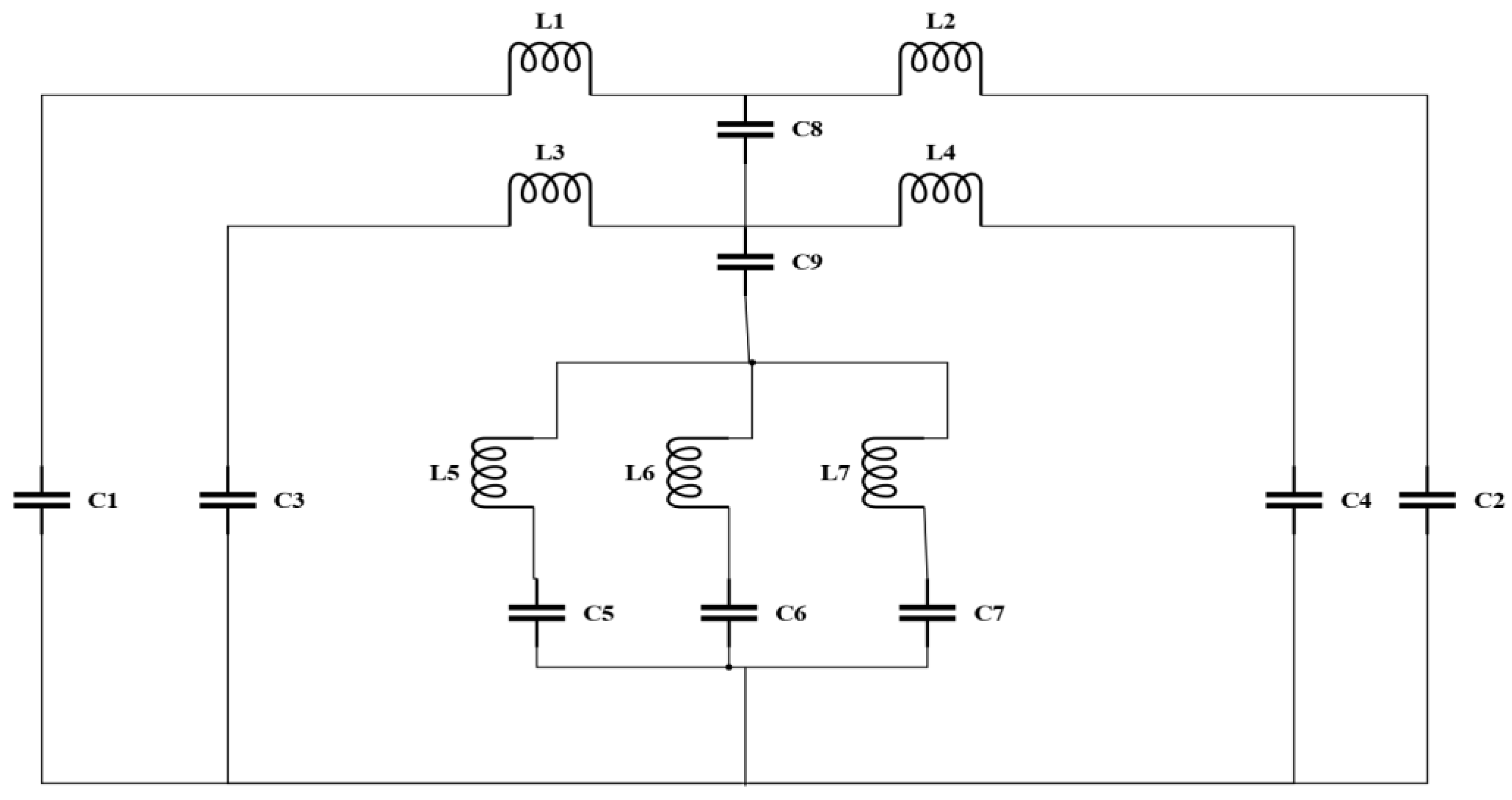
Figure 11 represents a predictable equivalent circuit for the proposed metamaterial unit cell. In the equivalent circuit L1, L2, L3, L4, L5, L6 and L7 depict the inductors while C1 to C9 represent the capacitors. The equivalent circuit for the proposed unit cell was performed using the advanced design system (ADS) software. The first SRR is represented by the inductors L1, L2 and capacitors C1, C2, respectively, which belong to the first resonance frequency of 2.375 GHz. Similarly, L3, L4 and C3, C4 are used for the second SRR, contributing to the second frequency of 4.52 GHz. Meanwhile, the two epsilon-shaped resonators are replaced by the inductors L5 to L7 and the capacitors C5 to C7, which are responsible for the third resonance frequency of 9.35 GHz, where C8 and C9 are the coupling capacitors. The values of all inductors and capacitors are tabulated in Table 3. The two transmission coefficients (S21) for the unit cell extracted from CST and ADS are presented in the Figure 12. Based on Figure 12, the 3 resonance frequencies that were attained by ADS simulation are 2.375 GHz, 4.52 GHz and 9.35, whereas the CST-simulated frequencies were 2.38 GHz, 4.55 GHz and 9.24 GHz, indicating very negligible disparity.
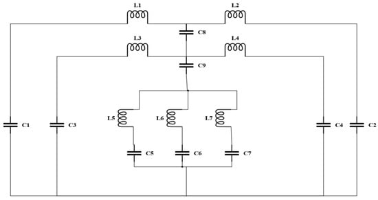
Figure 11.
Equivalent circuit model of unit cell.
Table 3.
The values equivalent circuit components.
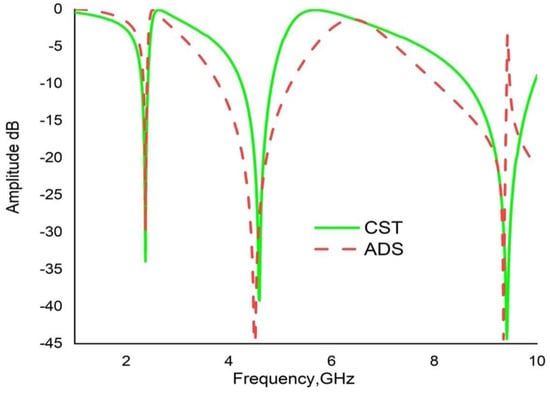
Figure 12.
Transmission coefficients (S21) result for CST and ADS simulation.
6. Results and Discussion
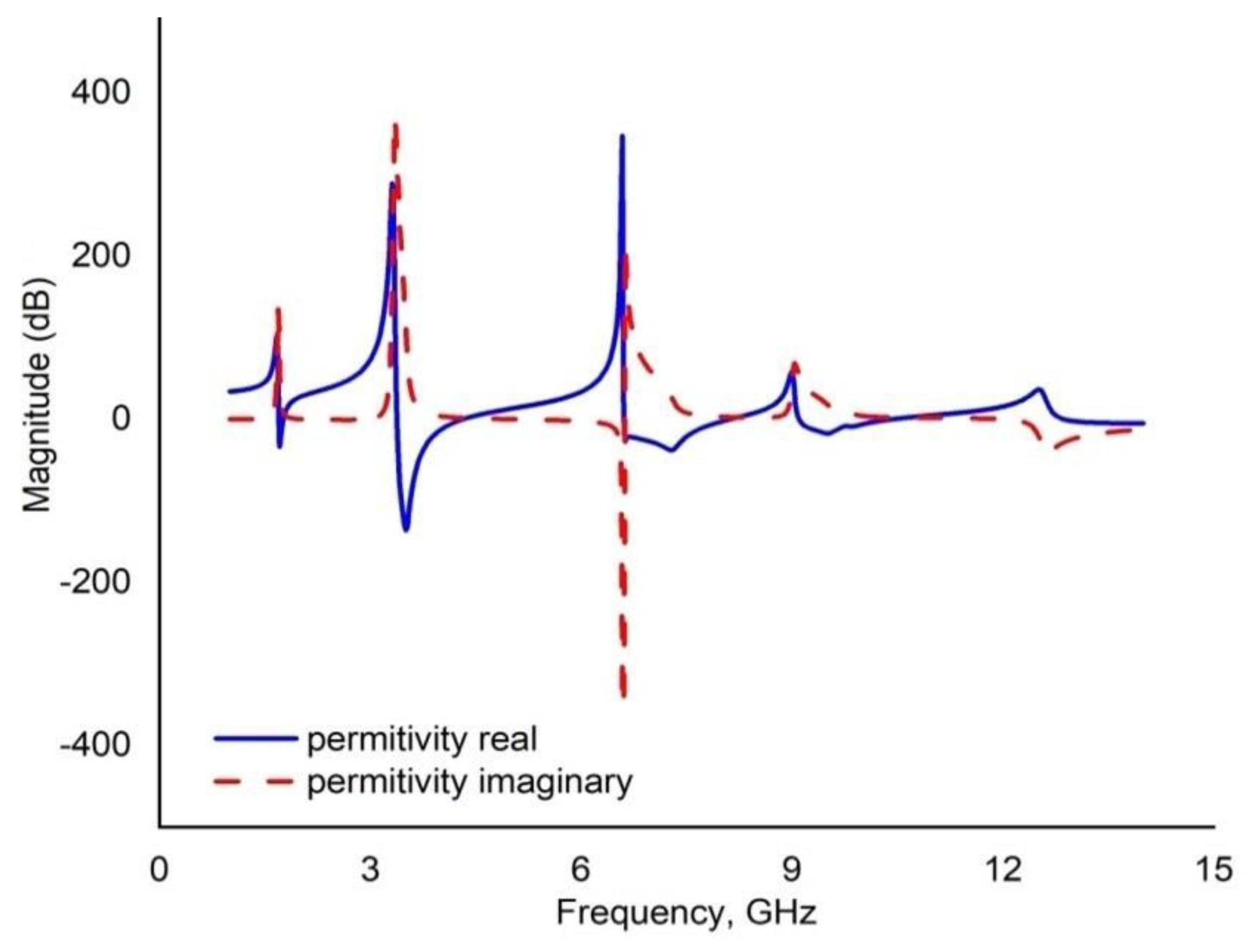
Finite Integration Technique (FIT)-based electromagnetic simulator CST microwave studio was used to analyse the S-parameter and the various material characteristics parameters. Figure 13 illustrates the CST results of the reflection coefficient and transmission coefficient. The simulated result of S21 exhibited triple band resonance at 2.38 GHz, 4.55 GHz and 9.42 GHz with the magnitudes of −29.40 dB, −39.65 dB and −43.35 dB, respectively. Meanwhile, S11 is observed at 2.64 GHz, 5.65 GHz and 11.2 GHz with magnitudes of −34.85 dB, −27.38 dB and −17.19 dB, respectively. The bandwidths of three resonance peaks for the concerned bands are shown in Figure 13: These are 0.124 GHz at S-band, 0.597 GHz at C-band and 1.288 GHz at X-band. Figure 13 indicates that the first resonance of the reflection coefficient (S11) pursued by the minimum value of transmission coefficient (S21). Every minimum frequency of S11 is lower than that of the corresponding S21 maximum frequency, where each resonance of the unit cell was addressed as an electrical resonance. Meanwhile, Figure 14, Figure 15 and Figure 16 represent the three important material characteristics, namely, the permittivity (εr), permeability (µr) and refractive index (n) derived using NRW method via MATLAB programming code. According to Figure 14, the is noticed that resonance of transmission coefficient (S21) just started while the values of ε changes from highest to the lowest. The smallest value of permeability (µ) was achieved when the value of the reflection coefficient (S11) was the lowest (Figure 15). At the positive permeability, the value of permittivity shifted from positive to negative. The refractive index (n) of a material is also regarded as a function of frequency. It denoted a negative value when permittivity (ε) was negative, as demonstrated in Figure 16. The permittivity of the proposed metamaterial was negative for a certain frequency range. Therefore, it can be termed as an ε-negative (ENG) metamaterial. The Drude equation can be used to explain the negative permittivity [33]:
where Γ and denote the energy disintegration attenuation function in the plasmons and plasmon frequency, respectively. If the losses Γ ≈ 0 and ω < ωp, then the permittivity ε becomes negative. This artificial characteristic of the projected MM is utilised in many types of wireless communication such as antenna bandwidth development [34]. Furthermore, the other NRI properties can numerously be used to enhance the antenna gain, cloaking and application.
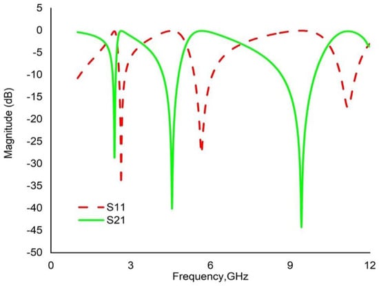
Figure 13.
CST-simulated result of reflection coefficient (S11) and transmission coefficient (S21) of a unit cell.

Figure 14.
Permittivity (ε) of real and imaginary magnitude for the unit cells.
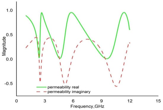
Figure 15.
Permeability (µ) of real and imaginary of unit cells.
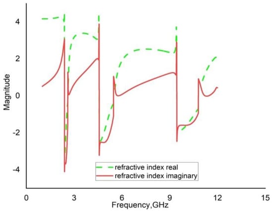
Figure 16.
Refractive index (n) real and imaginary of unit cell.
6.1. Array Metamaterial Results
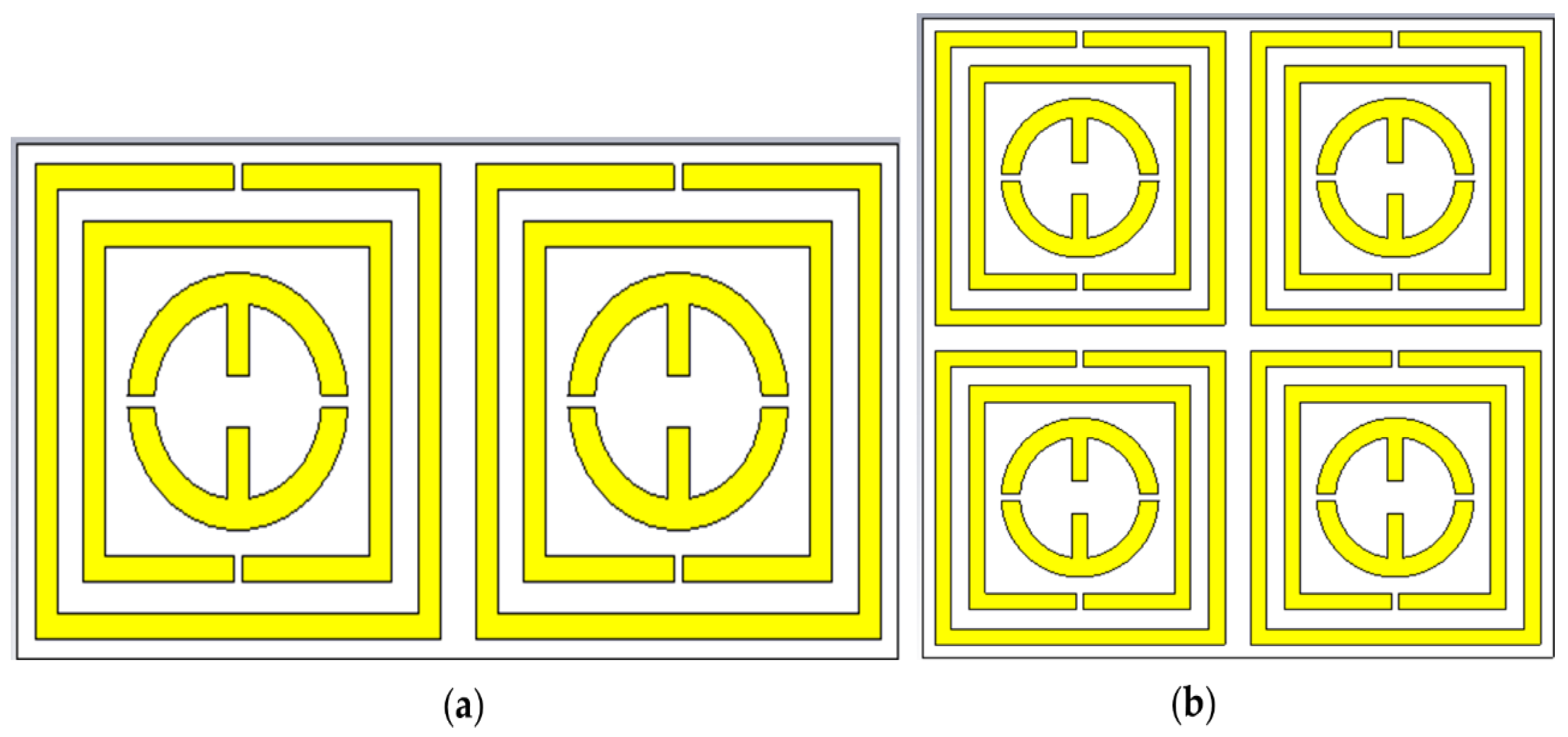
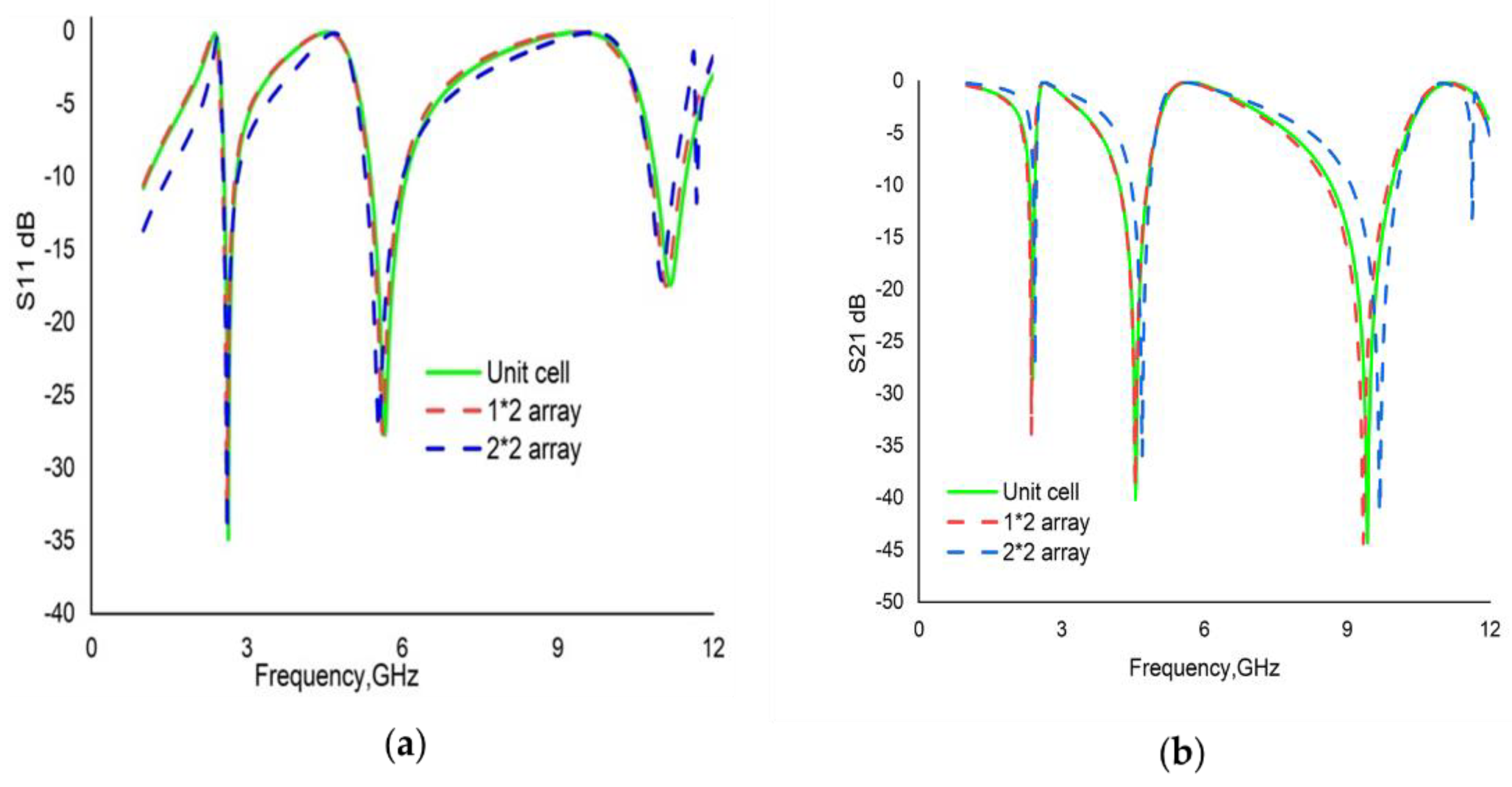
A unit cell itself cannot satisfactorily function independently. To obtain the expected electromagnetic properties from a metamaterial, an array of the unit cell was used. The 1 × 2 and 2 × 2 arrays of the proposed unit cell with the same substrate material are illustrated in the Figure 17a,b. To investigate the coupling effect among the proposed unit cell for different orientations of an array, a parametric study was performed whereby it generated an almost similar response as S21 to the unit cell. Therefore, the efficiency of the array was also observed. Figure 18a,b present the statistical results of S11 and S21, respectively, by CST of arrays with the proposed unit cell. By assessing the simulated results of the arrays, a change in the resonance frequencies was observed for the new array metamaterial. A comparative view of three resonance frequencies of two arrays in addition to the unit cell is shown in Table 4. The third frequency (9.42 GHz) is shifted nearly 2%, while the other 2 frequencies (2.38 GHz and 4.55 GHz) shifted only by 1%.
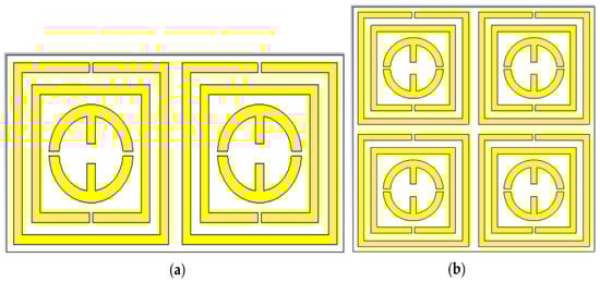
Figure 17.
(a) 1 × 2 array; (b) 2 × 2 array.
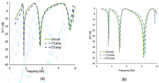
Figure 18.
Comparison of S-parameter: (a) reflection coefficient (S11); (b) transmission coefficient (S21).
Table 4.
Variation in resonance frequencies for different arrays with the PMA unit cell.
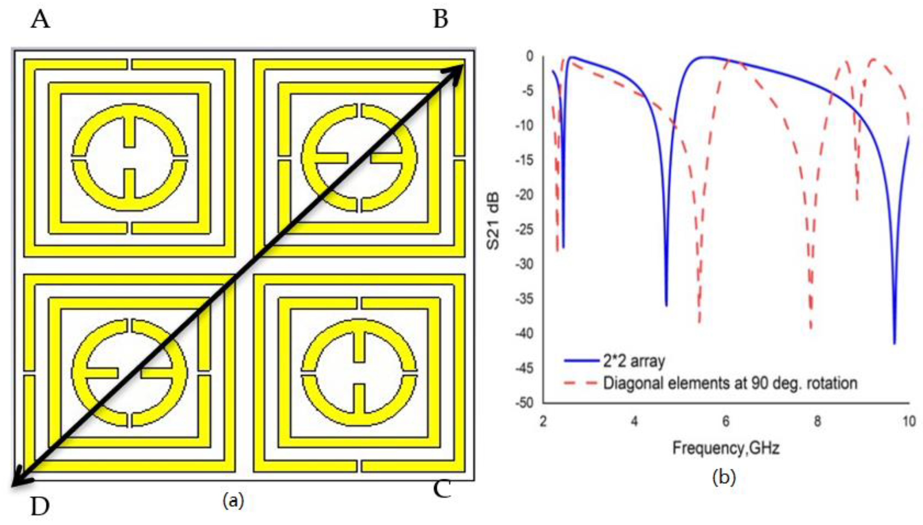
A, B, C, and D are the four positions of unit cell in the 2 × 2 array. If the two elements of the diagonal BD rotate at an angle of 90° compared to another two diagonal elements of the Figure 17b, as shown in Figure 19a, interesting and magical changes are observed in the numerical result. Four resonance peaks were observed at 2.27 GHz, 4.46 GHz, 7.76 GHz and 9.21 GHz for the S21 result at the new orientation, whereas, for Figure 17b, the simulated result shows three resonance peaks at 2.40 GHz, 4.60 GHz and 9.60 GHz. Figure 19b compares the two settings.
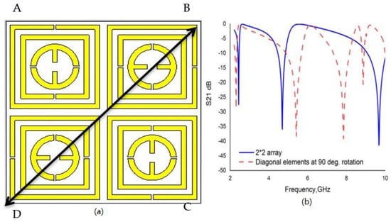
Figure 19.
(a) 2 × 2 array of diagonal elements for 90° rotation; (b) Comparison of S21 results. A, B, C and D are the four positions of unit cell in the 2 × 2 array.
6.2. Validation by Using HFSS
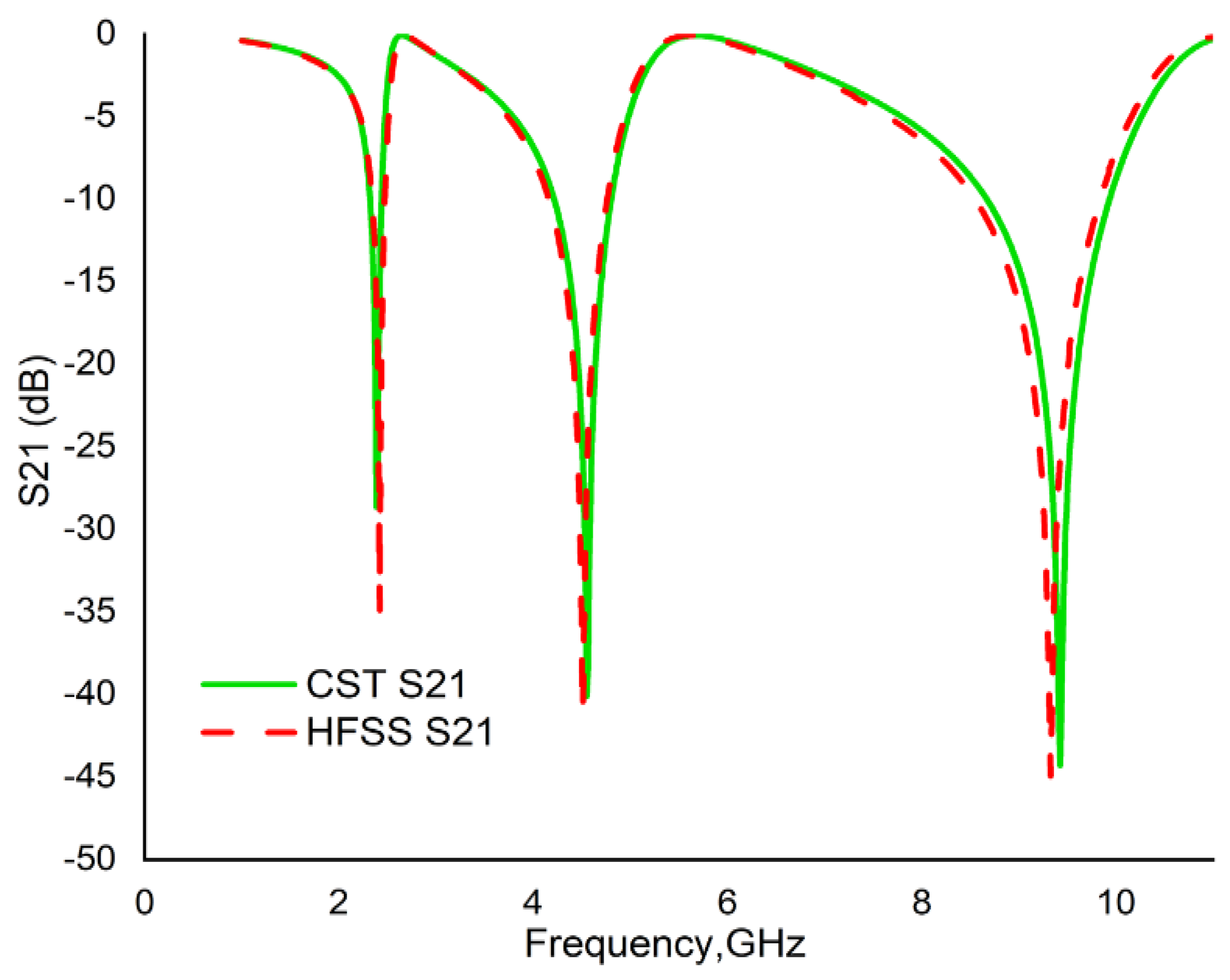
The CST result of S21 for the unit cell was also validated using the FEM based software HFSS. The proposed metamaterial unit cell exhibited 3 resonance peaks with almost similar magnitude at 2.40 GHz, 4.50 GHz and 9.40 GHz, whereas the CST yielded resonances at 2.38 GHz, 4.55 GHz and 9.42 GHz. Therefore, the CST and HFSS results were in excellent harmony (Figure 20). Table 5 represents the EMR of some previously reported metamaterials based on dimension, resonance frequency and frequency band.
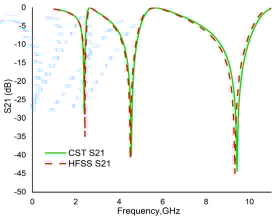
Figure 20.
Comparison of transmission coefficient (S21) by CST and HFSS results.
Table 5.
Verification of some previously reported MM with the offered configuration.
7. Conclusions
A triple-band, ε-negative, double-epsilon-shaped metamaterial was designed in this study. The presented work deliberated a metamaterial (10 × 10 × 1.524 mm3) on Rogers RT6002 (lossy) substrate. The unit cell of the proposed MM was simulated using the CST microwave and exhibited three resonance peaks at frequencies 2.38 GHz, 4.55 GHz and 9.42 GHz covering S-, C- and X-bands. The simulated results were authenticated using different validations such as equivalent circuit model, HFSS and array orientation. The significant material characteristics, namely, permittivity, permeability and refractive index, were extracted using the NRW-method-based MATLAB software. To investigate the response and activities of different resonators for the incident EM wave, an analysis was executed to assess the electric field, magnetic field and surface current. The 1 × 2 array and 2 × 2 arrays were simulated to compare the performance of the metamaterial. A good harmony was observed among the performance of ADS, HFSS and array. The designed unit cell yielded an EMR of 12.61 at the lower frequency of 2.38 GHz confirming compact size based on the compact metamaterial standard, L < λ/4. In conclusion, the proposed metamaterial can be used to boost the performance of different microwave devices for their n-negative and epsilon-negative characteristics. Since the S-, C- and, X-bands are frequently deployed for satellite and radar applications, the proposed MM may be a good candidate to improve the performance of satellite and radar communication devices.
Author Contributions
Conceptualization, M.S.U.A. and M.R.I.F.; methodology, M.S.U.A. and M.R.I.F.; software, M.S.U.A.; validation, M.S.U.A. and M.R.I.F.; formal analysis, M.S.U.A. and M.R.I.F.; investigation, M.S.U.A. and M.R.I.F.; data curation, M.S.U.A.; writing—original draft preparation, M.S.U.A.; writing—review and editing, M.S.U.A., M.R.I.F. and M.U.K.; visualization, M.S.U.A., M.R.I.F., M.U.K., A.A. and D.A.B.; supervision, M.R.I.F.; project administration, M.R.I.F.; funding acquisition, A.A. All authors have read and agreed to the published version of the manuscript.
Funding
This work was supported by the Research Universiti Grant, Universiti Kebangsaan Malaysia, Geran Universiti Penyelidikan (GUP), code: 2021-074.
Institutional Review Board Statement
Not applicable.
Informed Consent Statement
Not applicable.
Data Availability Statement
Not applicable.
Conflicts of Interest
The authors declare no conflict of interest.
References
- Suzuki, T.; Harumi, A. Reflectionless zero refractive index metasurface in the terahertz waveband. Opt. Express 2020, 28, 21509–21521. [Google Scholar] [CrossRef] [PubMed]
- Hossain, M.J.; Faruque, M.R.I.; Islam, M.T. Effective medium ratio obeying wideband left-handed miniaturized meta-atoms for multi-band applications. J. Electron. Mater. 2018, 47, 1859–1870. [Google Scholar] [CrossRef]
- Veselago, V.G. The electrodynamics of substances with simultaneously negative values of ε and μ. Sov. Phys. Uspekhi 1968, 10, 509–514. [Google Scholar] [CrossRef]
- Hossain, M.J.; Faruque, M.R.I.; Islam, M.T. Correction: Perfect metamaterial absorber with high fractional bandwidth for solar energy harvesting 2019. PLoS ONE 2019, 14, e0211751. [Google Scholar] [CrossRef] [Green Version]
- Emadi, R.; Reza, S.A.; Zeidaabadi, N. Plasmonic cloaking for irregular inclusions using an epsilon-near-zero region composed of a graphene–silica stack. JOSA B 2018, 35, 643–651. [Google Scholar] [CrossRef]
- Askari, M.; Hosseini, M.V. A novel metamaterial design for achieving a large group index via classical electromagnetically induced reflectance. Opt. Quantum Electron. 2020, 52, 19. [Google Scholar] [CrossRef]
- Zarghooni, B.; Abdolmehdi, D.; Tayeb, A.D. Greek-key pattern as a miniaturized multiband metamaterial unit-cell. IEEE Antennas Wirel. Propag. Lett. 2015, 14, 1254–1257. [Google Scholar] [CrossRef]
- Afsar, S.U.; Faruque, M.R.; Hossain, M.J.; Khandaker, M.U.; Osman, H.; Alamri, S. Modified hexagonal split ring resonator based on an epsilon-negative metamaterial for triple-band Satellite Communication. Micromachines 2021, 12, 878. [Google Scholar] [CrossRef]
- Smith, K.L.; Adams, R.S. Spherical spiral metamaterial unit cell for negative permeability and negative permittivity. IEEE Trans Antennas Propag. 2018, 66, 6425–6428. [Google Scholar] [CrossRef]
- Dalgac, S.; Karadağ, F.; Ünal, E.; Özkaner, V.; Bakır, M.; Akgöl, O.; Sevim, U.K.; Delihacıoğlu, K.; Öztürk, M.; Karaaslan, M.; et al. Metamaterial sensor application concrete material reinforced with carbon steel fiber. Mod. Phys. Lett. B 2020, 34, 2050097. [Google Scholar] [CrossRef]
- Sabah, C.; Nesimoglu, T. Design and characterization of a resonator-based metamaterial and its sensor application using microstrip technology. Opt. Eng. 2016, 55, 027107. [Google Scholar] [CrossRef]
- Faruque, M.R.I.; Ahamed, E.; Rahman, M.A.; Islam, M.T. Flexible nickel aluminate (NiAl2O4) based dual-band double negative metamaterial for microwave applications. Results Phys. 2019, 14, 102524. [Google Scholar] [CrossRef]
- Guo, Y.; Zhao, J.; Hou, Q.; Zhao, X. Omnidirectional broadband patch antenna with horizontal gain enhanced by epsilon-negative metamaterial superstrate. Microw. Opt. Technol. Lett. 2019, 62, 778–788. [Google Scholar] [CrossRef]
- Liu, S.H.; Guo, L.X.; Li, J.C. Left-handed metamaterials based on only modified circular electric resonators. J. Mod. Opt. 2016, 63, 2220–2225. [Google Scholar] [CrossRef]
- Ünal, E.; Bağmancı, M.; Karaaslan, M.; Akgol, O.; Sabah, C. Strong absorption of solar energy by using wide band metamaterial absorber designed with plus-shaped resonators. Int. J. Mod. Phys. B 2018, 32, 1850275. [Google Scholar] [CrossRef]
- Abdolrazzaghi, M.; Katchinskiy, N.; Elezzabi, A.Y.; Light, P.E.; Daneshmand, M. Noninvasive glucose sensing in aqueous solutions using an active split-ring resonator. IEEE Sens. J. 2021, 21, 18742–18755. [Google Scholar] [CrossRef]
- Kazemi, N.; Schofield, K.; Musilek, P. A high-resolution reflective microwave planar sensor for sensing of vanadium electrolyte. Sensors 2021, 21, 3759. [Google Scholar] [CrossRef]
- Song, X.; Yan, S. High-sensitivity planar microfluidic sensor based on zeroth-order resonance. In Proceedings of the IEEE 3rd International Conference on Electronic Information and Communication Technology (ICEICT), Shenzhen, China, 13–15 November 2020. [Google Scholar]
- Shelby, R.A.; Smith, D.R.; Seldon, S. Experimental verification of a negative index of refraction. Science 2001, 292, 77–79. [Google Scholar] [CrossRef] [Green Version]
- Pendry, J.B.; Holden, A.J.; Robbins, D.J.; Stewart, W. Magnetism from conductors and enhanced nonlinear phenomena. IEEE Trans. Microw. Theory Tech. 1999, 47, 2075–2084. [Google Scholar] [CrossRef] [Green Version]
- Marathe, D.; Kulat, K. A compact triple-band negative permittivity metamaterial for C, X-band applications. Int. J. Antennas Propag. 2017, 2017, 1–12. [Google Scholar] [CrossRef] [Green Version]
- Liu, P.; Yang, S.; Jain, A.; Wang, Q.; Jiang, H.; Song, J. Tunable meta-atom using liquid metal embedded in stretchable polymer. J. Appl. Phys. 2015, 118, 014504. [Google Scholar] [CrossRef] [Green Version]
- Islam, M.R.; Samsuzzaman, M.; Misran, N.; Beng, G.K.; Islam, M.T. A tri-band left-handed meta-atom enabled designed with high effective medium ratio for microwave based applications. Results Phys. 2020, 17, 103032. [Google Scholar] [CrossRef]
- Ramachandran, T.; Faruque, M.R.; Islam, M.T.; Khandaker, M.U. Radar cross-section reduction using polarization-dependent passive metamaterial for satellite communication. Chin. J. Phys. 2022, 76, 251–268. [Google Scholar] [CrossRef]
- Almutairi, A.F.; Islam, M.S.; Samsuzzaman, M.; Islam, M.T.; Misran, N.; Islam, M.T. A complementary split ring resonator based metamaterial with effective medium ratio for C-band microwave applications. Results Phys. 2019, 15, 102675. [Google Scholar] [CrossRef]
- Gupta, N.; Saxena, J.; Bhatia, K.S.; Dadwal, N. Design of metamaterial-loaded rectangular patch antenna for satellite communication applications. Iran. J. Sci. Technol. Trans. Electr. Eng. 2018, 43, 39–49. [Google Scholar] [CrossRef]
- Ali, W.; Hamad, E.; Bassiuny, M.; Hamdallah, M. Complementary split ring resonator based triple band microstrip antenna for WLAN/WiMAX Applications. Radio Eng. 2017, 26, 78–84. [Google Scholar] [CrossRef]
- Sakli, H.; Abdelhamid, C.; Essid, C.; Sakli, N. Metamaterial-based antenna performance enhancement for MIMO System Aplications. IEEE Access 2021, 9, 38546–38556. [Google Scholar] [CrossRef]
- Bhasakar, R.Y.V.; Prasad, A.M.; Swamy, K.V. Metamaterial inspired compact penta-band antenna for Wi-Max, WLAN, Satellite Band and X-band applications. In Proceedings of the IEEE International Conference on Electronics, Computing and Communication Technologies 2020 (CONECCT), Bangalore, India, 2–4 July 2020. [Google Scholar]
- Gerson, R. A useful text for calculus-based physics. Phys. Teach. 1981, 19, 504. [Google Scholar] [CrossRef]
- Ahamed, E.; Faruque, M.R.I.; Mansor, M.F.B.; Islam, M.T. Polarization-dependent tunneled metamaterial structure with enhanced fields properties for X-band application. Results Phys. 2015, 15, 102530. [Google Scholar] [CrossRef]
- Islam, S.S.; Faruque, M.R.I.; Islam, M.T. An ENG metamaterial based wideband electromagnetic cloak. Microw. Opt. Technol. Lett. 2016, 58, 2522–2525. [Google Scholar] [CrossRef]
- Pendry, J.B.; Holden, A.; Stewart, W.; Youngs, I. Extremely low frequency plasmons in metallic mesostructures. Phys Rev Lett. 1996, 76, 4773. [Google Scholar] [CrossRef] [PubMed] [Green Version]
- Dawar, P.; De, A. Bandwidth enhancement of RMPA using ENG metamaterials at THz. In Proceedings of the 4th International Conference on Computer and Communication Technology, (ICCCT), Allahabad, India, 20–22 September 2013; pp. 11–16. [Google Scholar]
- Mallik, A.; Kundu, S.; Goni, M.O. Design of a novel two-rectangular U-shaped double negative metamaterial. In Proceedings of the International Conference on Informatics, Electronics and Vision (ICIEV), Dhaka, Bangladesh, 17–18 May 2013. [Google Scholar]
- Hossain, M.B.; Faruque, M.R.I.; Islam, S.S.; Islam, M.T. Modified double dumbbell-shaped split-ring resonator-based negative permittivity metamaterial for satellite communications with high effective medium ratio. Sci. Rep. 2021, 11, 19331. [Google Scholar] [CrossRef] [PubMed]
- Islam, S.; Faruque, M.R.I.; Islam, M. The design and analysis of a novel split-H-shaped metamaterial for multi-band Microwave Applications. Materials 2014, 7, 4994–5011. [Google Scholar] [CrossRef] [PubMed] [Green Version]
- Islam, M.; Islam, M.; Samsuzzaman, M.; Faruque, M.R.I.; Misran, N.; Mansor, M. A miniaturized antenna with negative index metamaterial based on modified SRR and CLS unit cell for UWB microwave imaging applications. Materials 2015, 8, 392–407. [Google Scholar] [CrossRef]
- Hasan, M.M.; Faruque, M.R.I. Left-handed metamaterial using Z-shaped SRR for multiband application by azimuthal angular rotations. Mater. Res. Express 2017, 4, 045801. [Google Scholar] [CrossRef]


Publisher’s Note: MDPI stays neutral with regard to jurisdictional claims in published maps and institutional affiliations. |
© 2022 by the authors. Licensee MDPI, Basel, Switzerland. This article is an open access article distributed under the terms and conditions of the Creative Commons Attribution (CC BY) license (https://creativecommons.org/licenses/by/4.0/).