
Unveiling the Mechanisms of High-Temperature 1/2[111] Screw Dislocation Glide in Iron–Carbon Alloys


Abstract
:1. Introduction
2. Materials and Methods
2.1. Carbon Effect on the Dynamics of Straight Dislocation
2.2. Kink Pair Formation Enthalpy
2.3. Self-Consistent Calculation of Dislocation Velocity in Binary Iron–Carbon Alloys
3. Results
4. Discussion
5. Conclusions
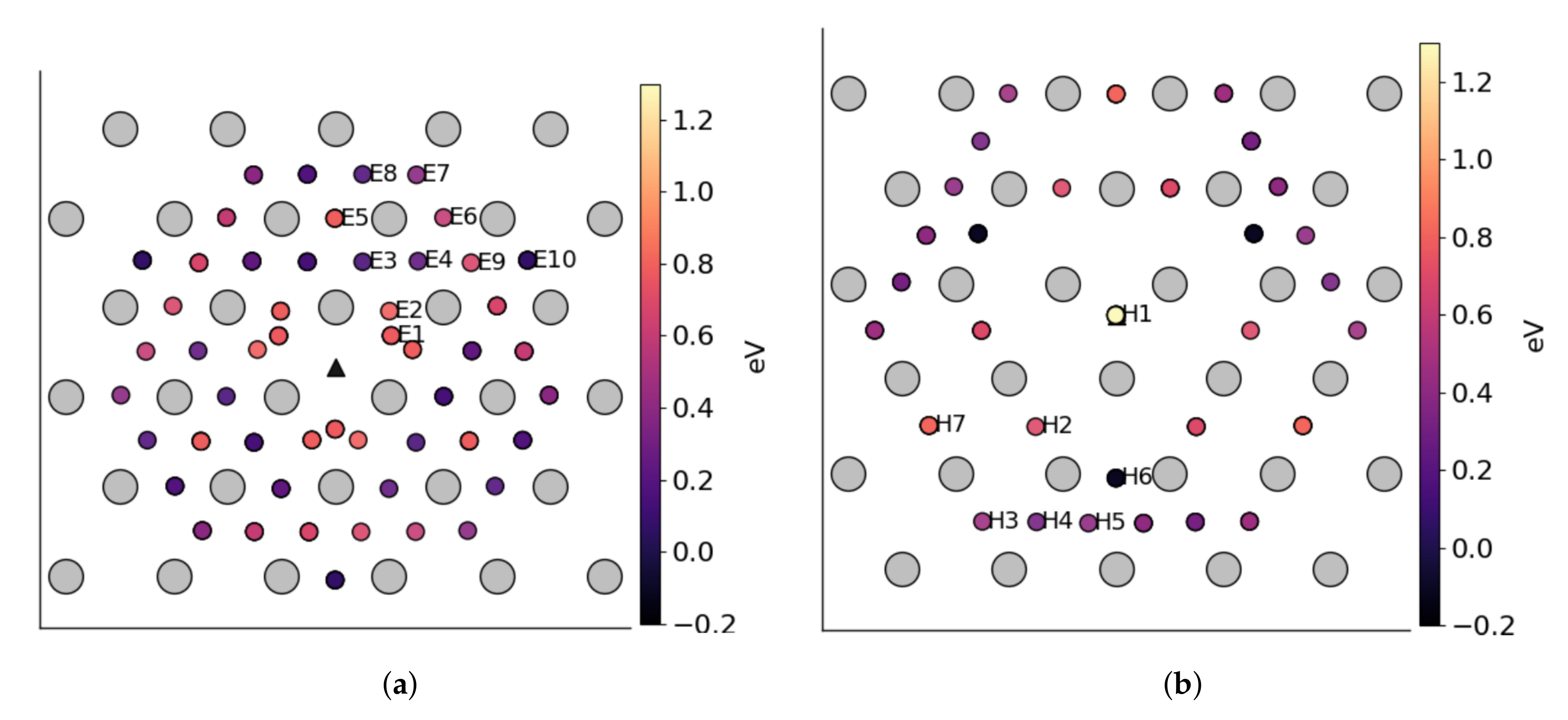
- KMC simulation of carbon segregation in dislocation core and determination the total carbon occupancy of the core binding sites.
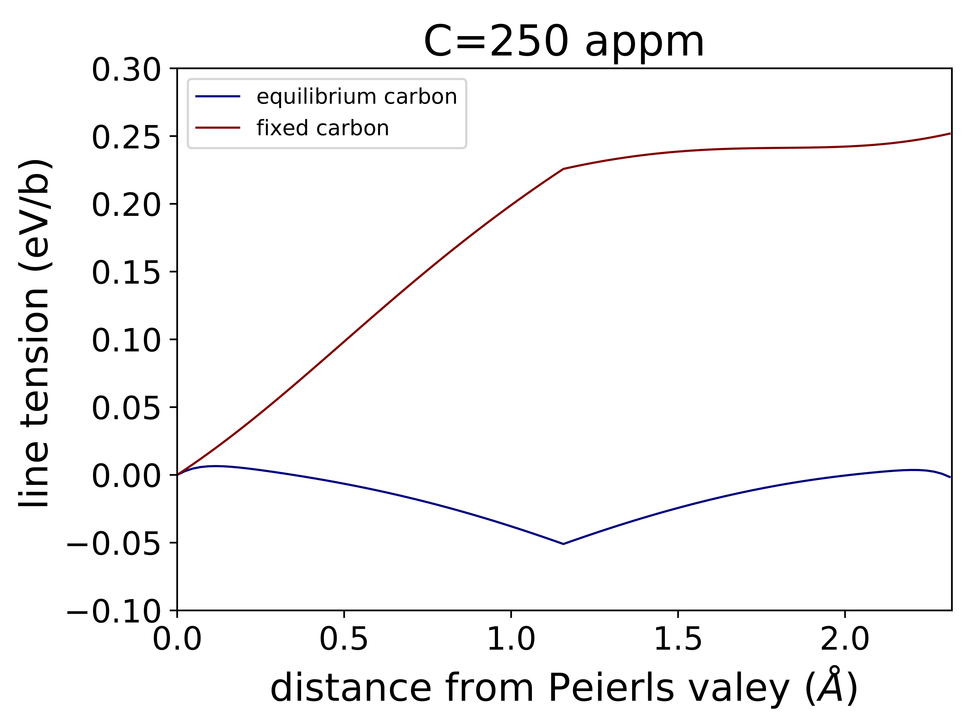
- Evaluation of the effect of trapped carbon on the motion of a straight dislocation segment between two adjacent Peierls valleys.
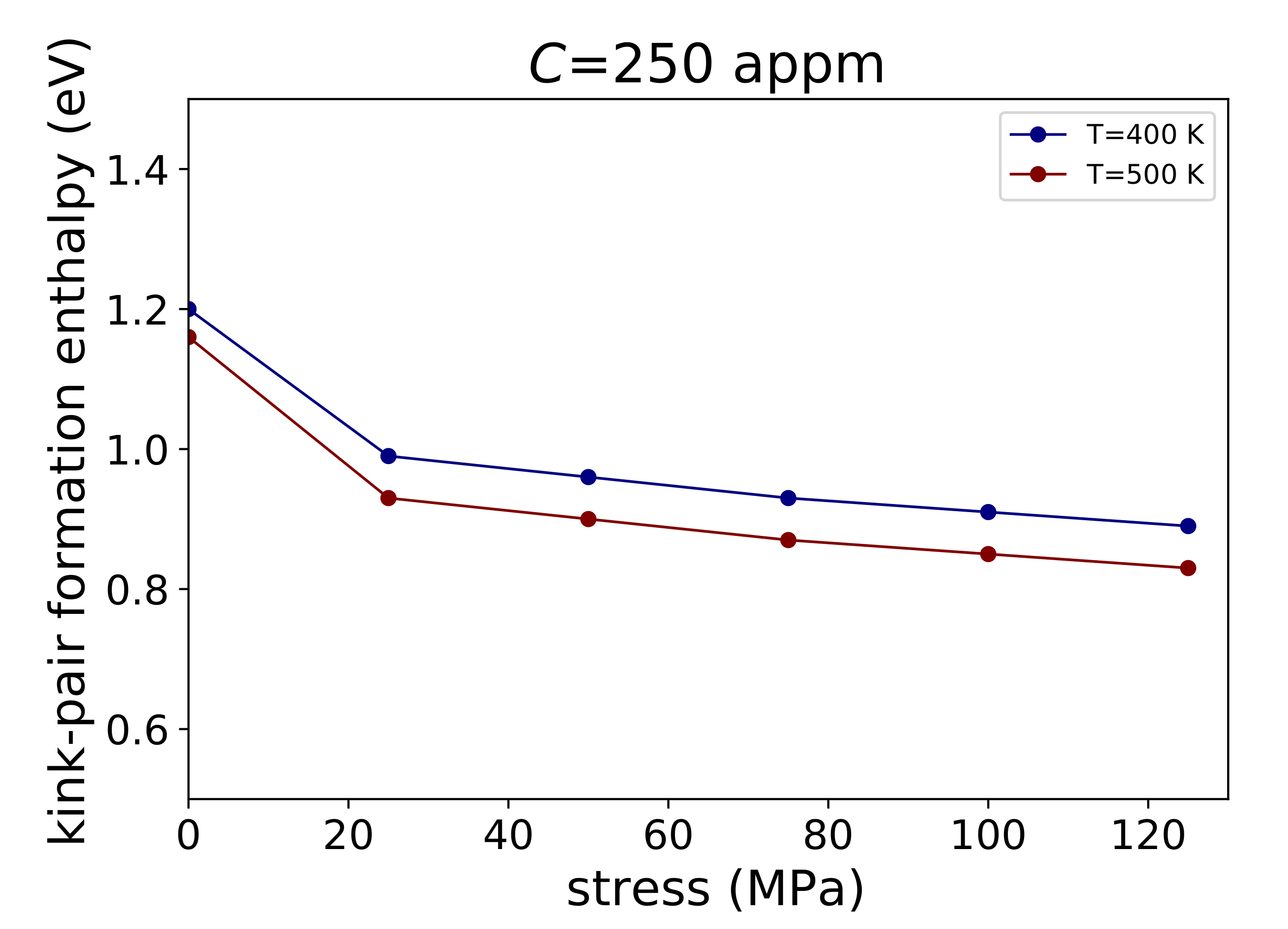
- Determination of kink-pair formation enthalpy of a screw dislocation in iron—carbon alloy.
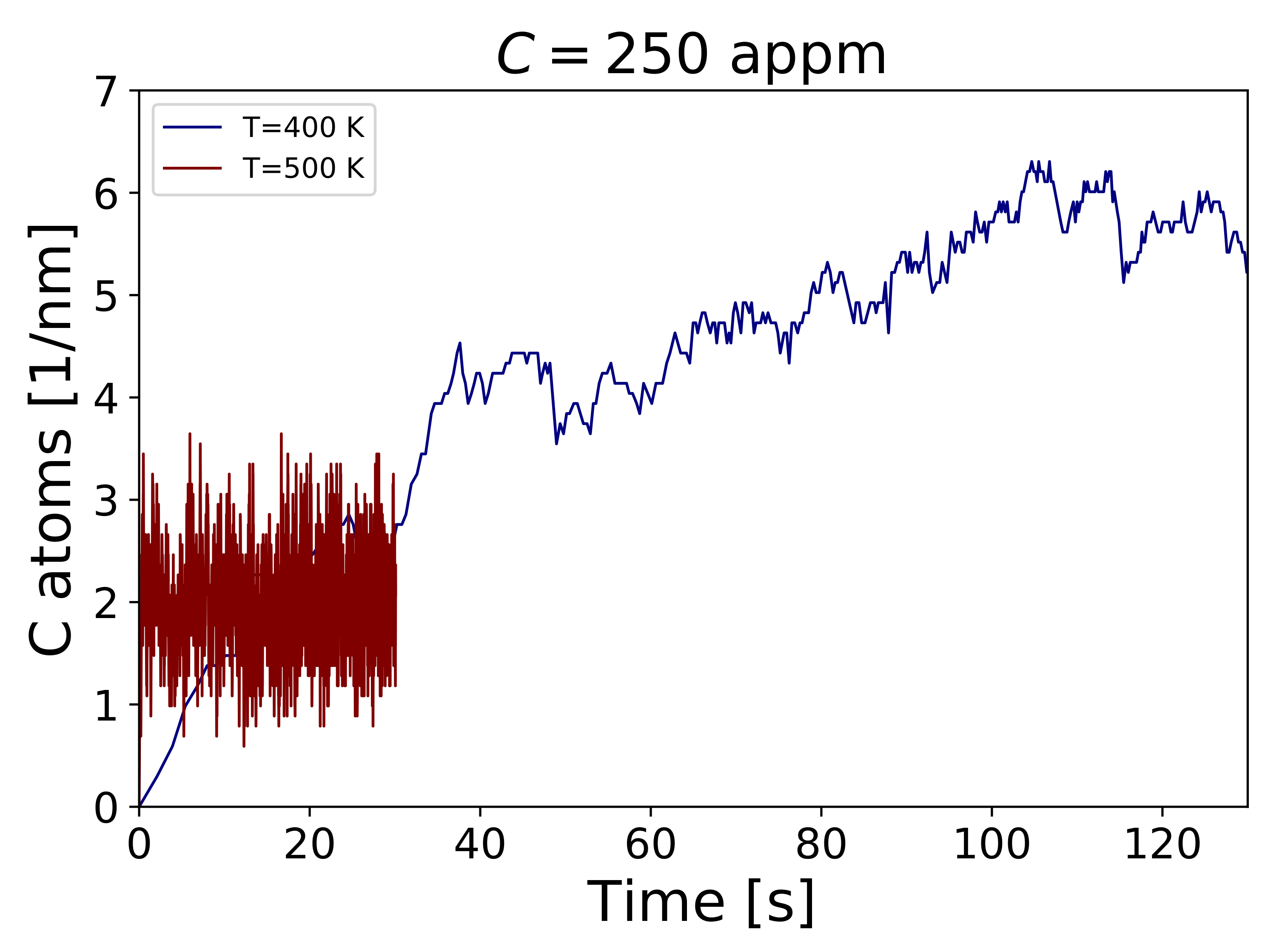
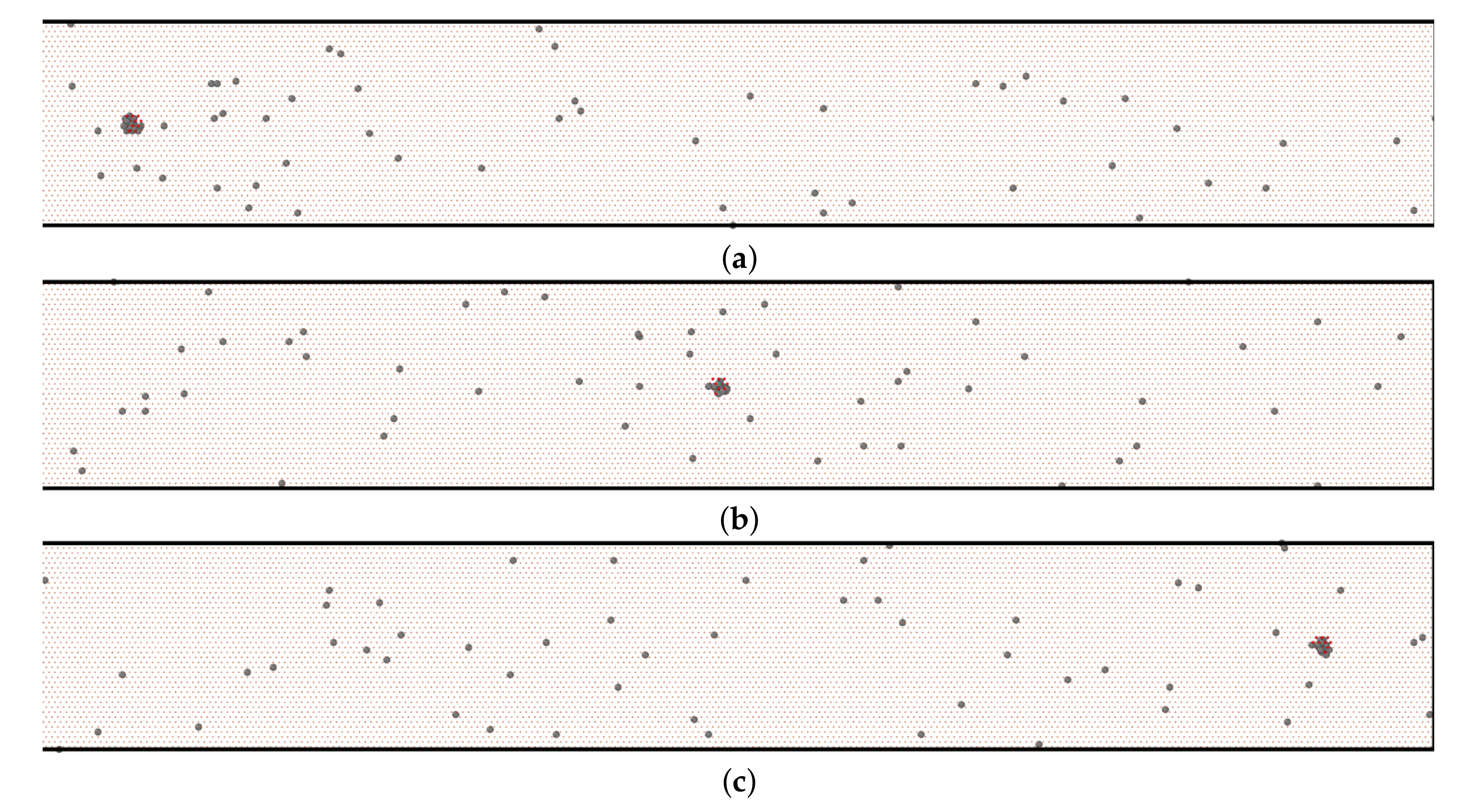
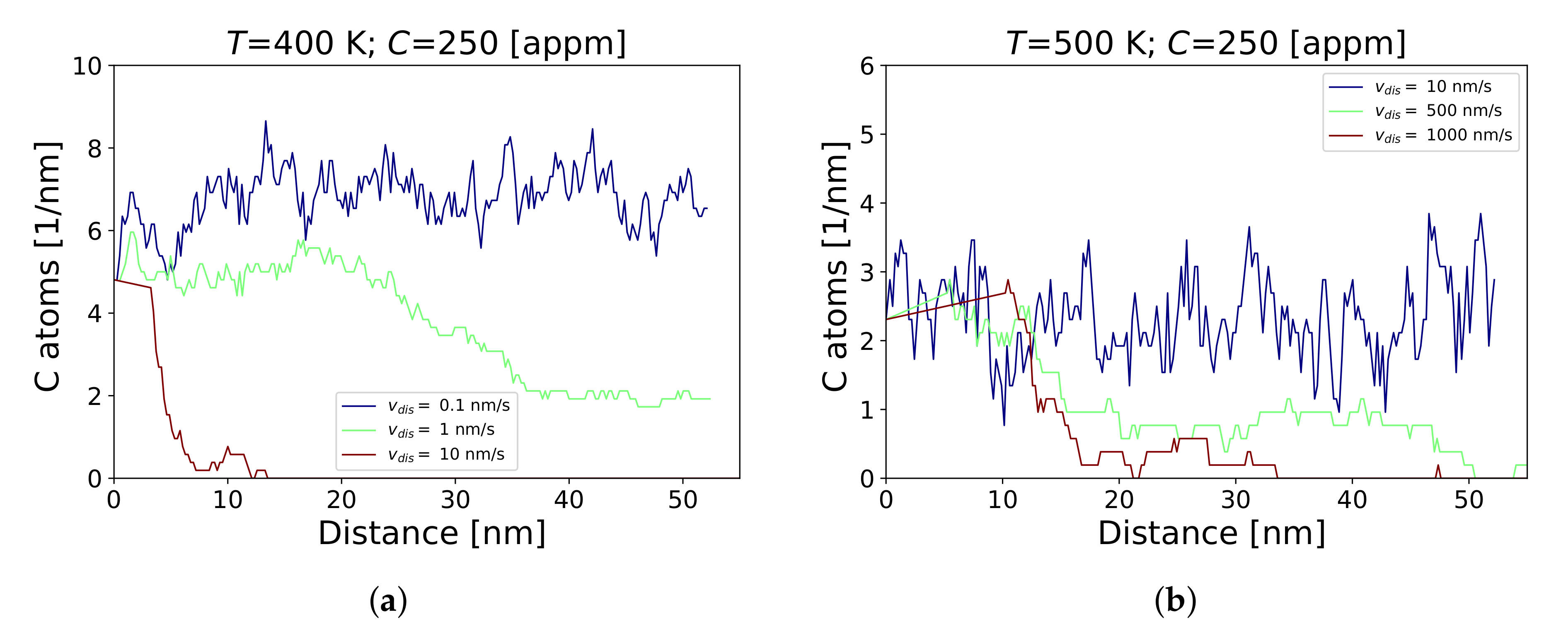
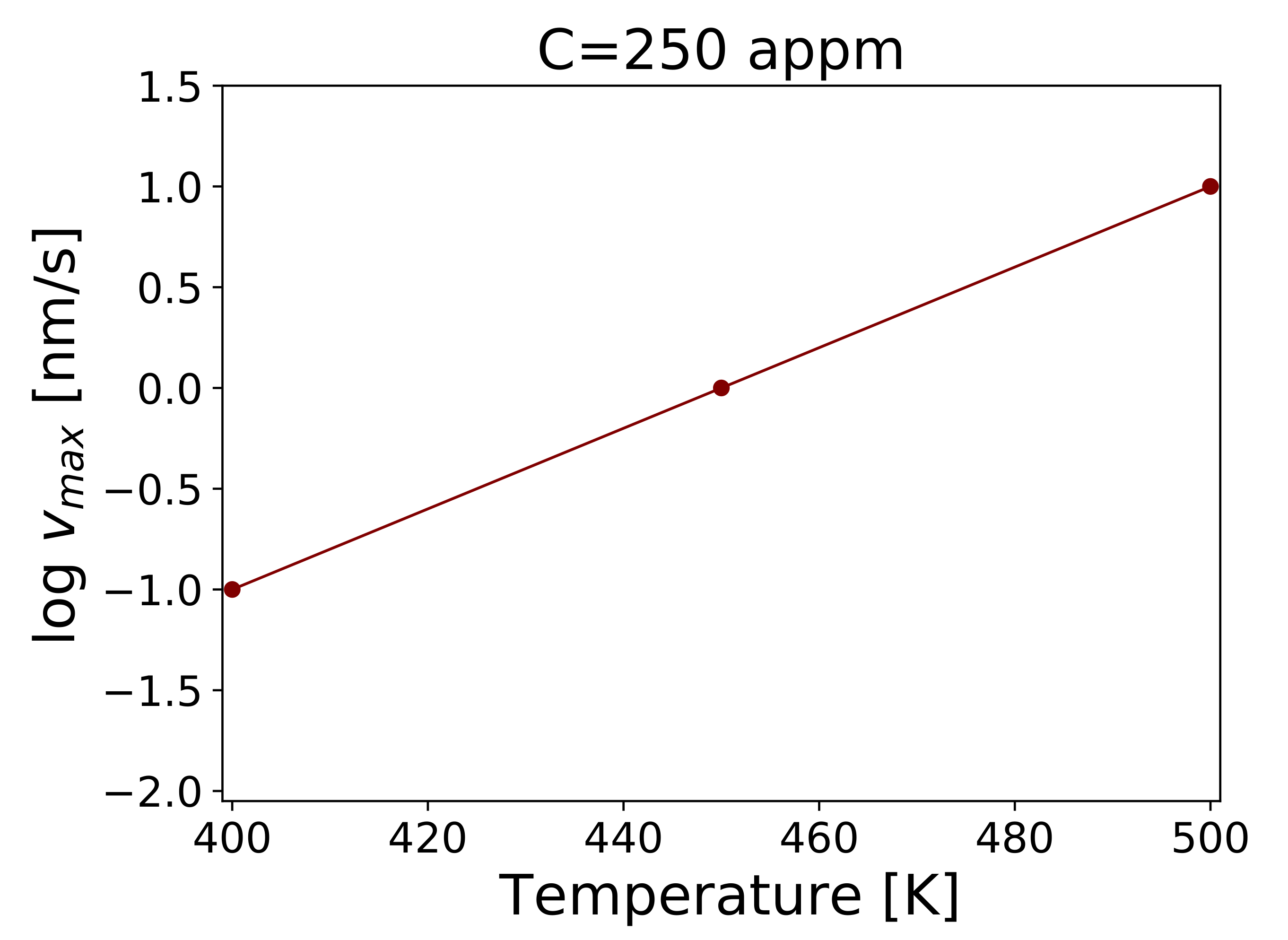
- KMC simulation of carbon drag and determination of maximal dislocation velocity at which the atmosphere of carbon atoms can follow a moving screw dislocation.
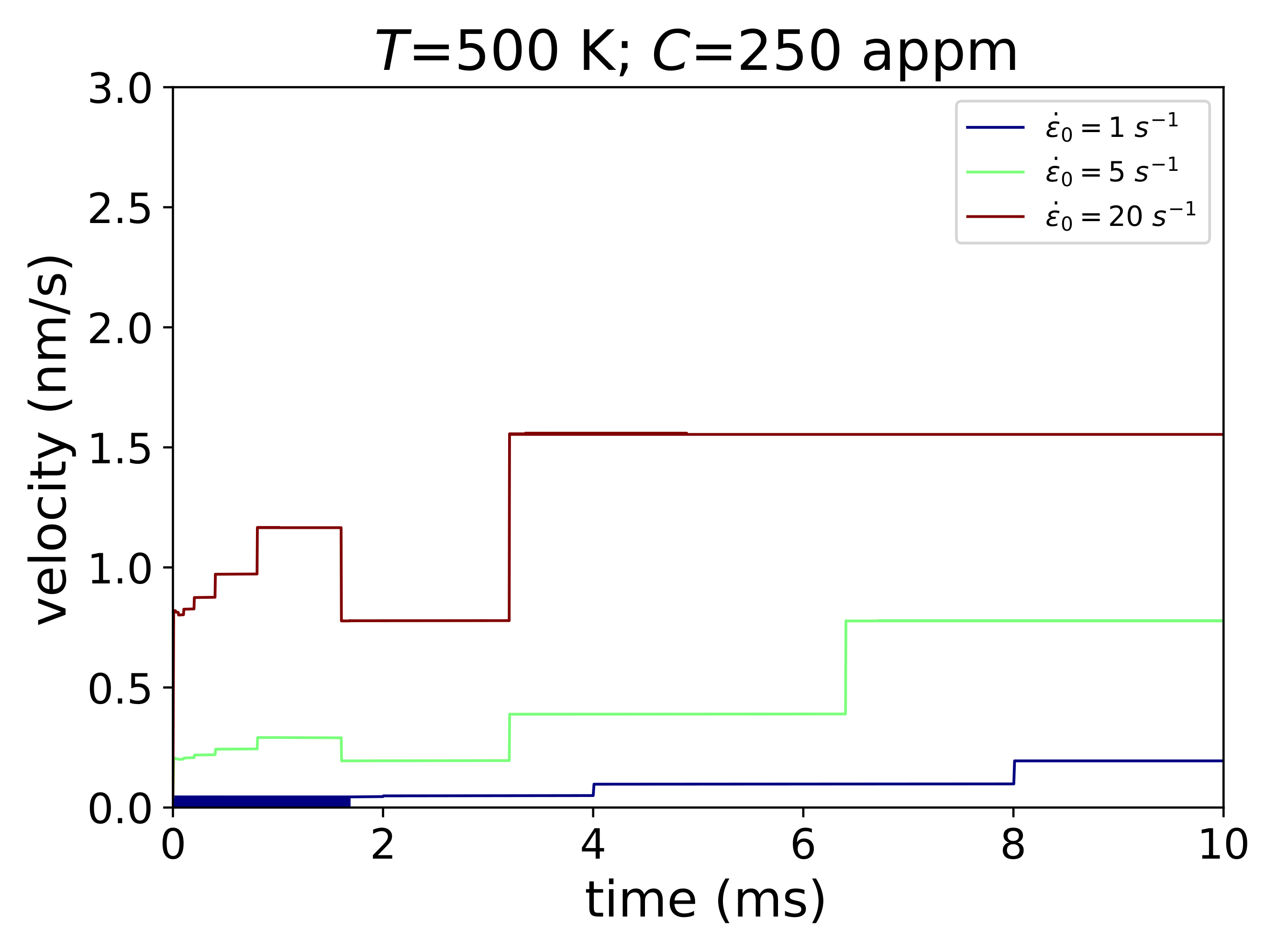
- Self consistent calculation of average velocity of screw dislocation in binary iron–carbon alloys gliding by a high-temperature kink-pair mechanism under constant strain rate.
- At high temperatures, kink-pair formation enthalpy decreases as a consequence of the increased carbon mobility in the dislocation core and reduced number of segregated C atoms.
- The enhanced diffusivity of carbon both in the core region and in dislocation surroundings lead to higher maximal dislocation velocity at which the atmosphere of carbon atoms can follow a moving screw dislocation.
Author Contributions
Funding
Institutional Review Board Statement
Informed Consent Statement
Data Availability Statement
Conflicts of Interest
References
- Caillard, D. An in situ study of hardening and softening of iron by carbon interstitials. Acta Mater. 2011, 59, 4974–4989. [Google Scholar] [CrossRef]
- Cottrell, A.H.; Bilby, B.A. Dislocation theory of yielding and strain ageing of iron. Proc. Phys. Soc. Sect. A 1949, 62, 49–62. [Google Scholar] [CrossRef]
- Clouet, E.; Garruchet, S.; Nguyen, H.; Perez, M.; Becquart, C.S. Dislocation interaction with C in α-Fe: A comparison between atomic simulations and elasticity theory. Acta Mater. 2008, 56, 3450–3460. [Google Scholar] [CrossRef] [Green Version]
- Li, Y.; Choi, P.; Borchers, C.; Westerkamp, S.; Goto, S.; Raabe, D.; Kirchheim, R. Atomic-scale mechanisms of deformation-induced cementite decomposition in pearlite. Acta Mater. 2011, 59, 3965–3977. [Google Scholar] [CrossRef]
- Allera, A.; Ribeiro, F.; Perez, M.; Rodney, D. Carbon-induced strengthening of bcc iron at the atomic scale. Phys. Rev. Mater. 2022, 6, 013608. [Google Scholar] [CrossRef]
- Patinet, S.; Bonamy, D.; Proville, L. Atomic-scale avalanche along a dislocation in a random alloy. Phys. Rev. B 2011, 84, 174101. [Google Scholar] [CrossRef] [Green Version]
- Zhao, Y.; Dezerald, L.; Pozuelo, M.; Zhou, X.; Marian, J. Simulating the mechanisms of serrated flow in interstitial alloys with atomic resolution over diffusive timescales. Nat. Commun. 2020, 11, 1–8. [Google Scholar] [CrossRef] [PubMed]
- Zhao, Y.; Marian, J. Direct prediction of the solute softening -to-hardening transition in W-Re alloys using stochastic simulations of screw dislocation motion. Model. Simul. Mater. Eng. 2018, 26, 045002. [Google Scholar] [CrossRef] [Green Version]
- Caillard, D. Dynamic strain ageing in iron alloys: The shielding effect of carbon. Acta Mater. 2016, 112, 273–284. [Google Scholar] [CrossRef]
- Katzarov, I.H.; Drenchev, L.B.; Pashov, D.L.; Zarrouk, T.N.A.T.; Al-lahham, O.; Paxton, A.T. Dynamic strain aging and the rôle Dynamic strain aging and the rôle of the Cottrell atmosphere. 2022; submitted. [Google Scholar]
- Nematollahi, G.A.; Grabowski, B.; Raabe, D.; Neugebauer, J. Multiscale description of carbon-supersaturated ferrite in severely drawn pearlitic wires. Acta Mater. 2016, 111, 321–334. [Google Scholar] [CrossRef] [Green Version]
- Wilde, J.; Cerezo, A.; Smith, G.D.W. Three-dimensional atomic-scale mapping of a Cottrell atmosphere around a dislocation in iron. Scr. Mater. 2000, 43, 39–48. [Google Scholar] [CrossRef]
- Gong, P.; Katzarov, I.H.; Nutter, J.; Paxton, A.T.; Rainforth, W.M. The influence of hydrogen on plasticity in pure iron–theory and experiment. Sci. Rep. 2020, 10, 10209. [Google Scholar] [CrossRef] [PubMed]
- Katzarov, I.H.; Pashov, D.L.; Paxton, A.T. Hydrogen embrittlement I. Analysis of hydrogen-enhanced localized plasticity: Effect of hydrogen on the velocity of screw dislocations in α-Fe. Phys. Rev. Mater. 2017, 1, 033602. [Google Scholar] [CrossRef] [Green Version]
- Itakura, M.; Kaburaki, H.; Yamaguchi, M.; Okita, T. The Effect of Hydrogen Atoms on the Screw Dislocation Mobility in Bcc Iron: A First-Principles Study. Acta Mater. 2013, 61, 18. [Google Scholar] [CrossRef]
- Clouet, E.; Ventelon, L.; Willaime, F. Dislocation core energies and core fields from first principles. Phys. Rev. Lett. 2009, 102, 055502. [Google Scholar] [CrossRef] [PubMed] [Green Version]
- Zarrouk, T. Atomistic Investigation of Dislocation-Assisted Carbon Migration in Iron. Ph.D. Thesis, King’s College London, London, UK, 2022. [Google Scholar]
- Paxton, A.T.; Elsässer, C. Analysis of a Carbon Dimer Bound to a Vacancy in Iron Using Density Functional Theory and a Tight Binding Model. Phys. Rev. B 2012, 87, 22. [Google Scholar] [CrossRef] [Green Version]
- Ventelon, L.; Lüthi, B.; Clouet, E.; Proville, L.; Legrand, B.; Rodney, D.; Willaime, F. Dislocation core reconstruction induced by carbon segregation in bcc iron. Phys. Rev. B 2015, 91, 220102(R). [Google Scholar] [CrossRef] [Green Version]
- Hirth, J.P.; Lothe, J. Theory of Dislocations, 1st ed.; McGraw-Hil Book Company: New York, NY, USA, 1968. [Google Scholar]
- Henkelman, G.; Jónsson, H. Improved tangent estimate in the nudged elastic band method for finding minimum energy paths and saddle points. J. Chem. Phys. 2000, 113, 9978–9985. [Google Scholar] [CrossRef] [Green Version]
- Itakura, M.; Kaburaki, H.; Yamaguchi, M. First-principles study on the mobility of screw dislocations in bcc iron. Acta Mater. 2012, 60, 3698–3710. [Google Scholar] [CrossRef] [Green Version]


Publisher’s Note: MDPI stays neutral with regard to jurisdictional claims in published maps and institutional affiliations. |
© 2022 by the authors. Licensee MDPI, Basel, Switzerland. This article is an open access article distributed under the terms and conditions of the Creative Commons Attribution (CC BY) license (https://creativecommons.org/licenses/by/4.0/).
Share and Cite
Katzarov, I.H.; Drenchev, L.B. Unveiling the Mechanisms of High-Temperature 1/2[111] Screw Dislocation Glide in Iron–Carbon Alloys. Crystals 2022, 12, 518. https://doi.org/10.3390/cryst12040518
Katzarov IH, Drenchev LB. Unveiling the Mechanisms of High-Temperature 1/2[111] Screw Dislocation Glide in Iron–Carbon Alloys. Crystals. 2022; 12(4):518. https://doi.org/10.3390/cryst12040518
Chicago/Turabian StyleKatzarov, Ivaylo Hristov, and Ljudmil Borisov Drenchev. 2022. "Unveiling the Mechanisms of High-Temperature 1/2[111] Screw Dislocation Glide in Iron–Carbon Alloys" Crystals 12, no. 4: 518. https://doi.org/10.3390/cryst12040518
APA StyleKatzarov, I. H., & Drenchev, L. B. (2022). Unveiling the Mechanisms of High-Temperature 1/2[111] Screw Dislocation Glide in Iron–Carbon Alloys. Crystals, 12(4), 518. https://doi.org/10.3390/cryst12040518