Article

Characterization of Tungstates of the Type Hf1−xLnxW2O8−x/2 (Ln = Eu, Tm, Lu) Synthesized Using the Hydrothermal Method

1
Laboratory of Rare and Rare Earth Elements, Department of Inorganic Chemistry, Faculty of Chemistry and Pharmacy, University of Sofia “St. Kliment Ohridski”, 1, J. Bourchier, 1164 Sofia, Bulgaria
2
Department of Condensed Matter Physics and Microelectronics, Faculty of Physics, University of Sofia “St. Kliment Ohridski”, 3, J. Bourchier, 1164 Sofia, Bulgaria
*
Authors to whom correspondence should be addressed.
Crystals 2022, 12(3), 327; https://doi.org/10.3390/cryst12030327
Submission received: 1 February 2022 / Revised: 21 February 2022 / Accepted: 23 February 2022 / Published: 26 February 2022
(This article belongs to the Special Issue Rare Earths-Doped Materials)

Abstract

:
Pure HfW2O8- and Ln3+-containing solid solutions, Hf1−xLnxW2O8−x/2 (Ln = Eu, Tm, Lu), were synthesized using the hydrothermal method. The lanthanide ions were selected based on the differences between their ionic radii. A content of the Ln3+ ions in the range of 0.01–0.15 mol with a step of 0.02 was used for Hf1−xLnxW2O8−x/2 preparation, although the main research was performed on x = 0.01 and 0.05 samples because of an inhomogeneity detected by powder X-ray diffraction (XRD) when the content of Ln3+ was above 0.07–0.09 mol. X-ray diffraction measurements were supported by Raman and infrared spectroscopy. A new band in the Raman spectra of the samples with 0.05 mol Ln3+, as well as a red shift of the most intensive band (assigned to valence stretching of W-O-W bonds) as a result of the Ln3+ presence, was detected. The Scanning Electron Microscopy and Transmission Electron Microscopy micrographs revealed well-crystalized microcrystals with lengths in the range of 2–5 μm, with larger interplanar distances, measured in the solid solutions of the same crystal plain. The alpha-HfW2O8 → beta-HfW2O8 order-to-disorder phase transition was followed by high temperature XRD, and its reversibility was evident. The influence of the Ln3+ both on the unit cell parameters of the solid solutions and on the temperature of phase transition and on the coefficient of thermal expansion, CTE, was observed. A band gap energy in the range of 2.8–3.1 eV for pure HfW2O8 and for the solid solutions Hf1−xLnxW2O8−x/2 (x = 0.01 and 0.05) was determined.

1. Introduction

Materials which contract upon heating, i.e., with negative thermal expansion (NTE), can play the role of thermal-expansion compensators, so they are considered important in the development of composites with adjustable thermal expansion [1,2,3]. Examples of these materials include various silicates [4], cyanide-bridged compounds [5], nickel-based perovskite oxide [6], and many others, reviewed in [7]. The isostructural tungstates from the group of the cubic AW2O8, A = Zr, Hf [8], are among these materials. The cubic AW2O8 have an open framework structure with WO4 tetrahedra sharing three of their four oxygen atoms with the adjacent AO6 octahedra [1,2,8,9,10]. ZrW2O8, as well as HfW2O8, shows an exceptionally large isotropic negative thermal expansion over an exceptionally large temperature range (0.3–1050 K) [8]. ZrW2O8 goes through an order–disorder change at about 440 K (167 °C) from a metastable, low-temperature cubic phase (alpha) with a coefficient of NTE of −9 × 10⁻⁶ K−1 to a metastable, high temperature cubic phase (beta) with a coefficient of NTE of −5 × 10⁻⁶ K−1 [8,10]. The NTE for HfW2O8 is less pronounced in the alpha-phase (−9 × 10⁻⁶ K−1) than in beta-phase (−6 × 10⁻⁶ K−1) with a temperature of order/disorder phase transition of 463 K [11], i.e., the absolute thermal expansion coefficient is slightly smaller for HfW2O8 than for ZrW2O8. Calorimetric studies show that the phase transition temperature is 24 K higher for HfW2O8 than for ZrW2O8, which is probably due to the stronger chemical bond of Hf-O than Zr-O [12]. In any case, ZrW2O8 and HfW2O8 show the low–high symmetry phase transition at similar temperatures and similar thermal contraction properties [9]. A phase transition from an alpha–phase to an orthorhombic gamma–phase induced under compression in both ZrW2O8 and HfW2O8 has been observed; significantly higher pressures are required to induce the transition in HfW2O8 than in ZrW2O8 [11]. The NTEs of those compounds originate from lattice vibrations, which could be affected by the masses and ionic radii of the constituent atoms [13]. The introduction of ions with different radii and charges can lead to a disorder in the crystalline structure of the tungstates and, consequently, to changes in their properties as detected by us for limited concentration ranges of Eu(III) on NTE and the phase transformation temperatures of ZrW2O8 [14]. The introduction of M4+, like Sn4+ and Ti4+ in tungstates [15,16], as well as the insertion of Y3+ and Lu3+ in HfW2O8, have been studied [17,18]. It has been found that even small amounts can led to essential changes in the temperatures of phase transitions, for instance, a 4% replacement decreases the temperature of the transition to 390 K for Y3+, 380 K for In3+ and 360 K for Sc3+ [17,18,19]. A series of solid solutions with a cubic ZrW2O8 structure, where the crystal sites of Zr4+ are substituted partially by lanthanide cations Ln3+ (Ln = Yb, Er, Eu), have been studied, and it has been found that the solubility of lanthanide cations in Zr1−xLnxW2O8−x/2 solid solutions increases as the radius of the lanthanide cations decrease [20]. In an attempt to expand the research, in this work, the influence of lanthanide ions Eu3+, Tm3+, and Lu3+ on the properties of HfW2O8 was followed by synthesis and characterization of solid solutions of the type Hf1−xLnxW2O8−x/2.

2. Materials and Methods

HfOCl22H2O (Sigma-Aldrich Chemie GmbH, Taufkirchen, Germany) and Na2WO42H2O (Aldrich Chemie GmbH, Taufkirchen, Germany) (both ACS grade) were used as starting materials. The nitrates Ln(NO3)3•nH2O were synthesized using Eu2O3 (Fluka Chemie GmbH, Buchs, Switzerland, p.a.), Tm2O3 (Sigma Aldrich, 99.99% Sigma-Aldrich Chemie GmbH, Taufkirchen, Germany), and Lu2O3 (Sigma Aldrich, 99.99% Sigma-Aldrich Chemie GmbH, Taufkirchen, Germany) by dissolving them in heated diluted HNO3 (70%, Sigma-Aldrich Chemie GmbH, Taufkirchen, Germany), followed by crystallization after the cooling of the solution. Titration with a 0.01 M water solution of a di-sodium salt of ethylene diammine tetraacetic acid Na2EDTA (99%+, Sigma-Aldrich Chemie GmbH, Taufkirchen, Germany) was applied to determine the amount of crystallization water in the nitrates synthesized.
The synthesis of HfW2O8: The initial water solutions of HfOCl2•2H2O (8.5 mL, 0.1 M) and Na2WO4 (8.5 mL, 0.1 M) were prepared with a calculated stoichiometric ratio of Hf/W = 1:2. The two solutions were added dropwise to 15 mL of distilled water simultaneously through dropping funnels. After mixing, the new solution (the white suspension) obtained was heated at 60 °C and stirred for 30 min. To obtain a homogeneous solution, 15 mL of 6 M HCl (37%, Sigma-Aldrich Chemie GmbH, Taufkirchen, Germany) was added (in order to obtain the final concentration of HCl about 3 M). An additional heating at 60 °C for 2 h was applied followed by adding of 5 mL 1-butanol. The solution obtained was heated in a 75 mL Teflon autoclave for 15 h at 180 °C, while stirring. Then, the obtained suspension was cooled down to room temperature followed by filtering, washing with water and ethyl alcohol, and drying at 50 °C. After calcination in preheated furnace for 1 h at 600 °C, the sample of HfW2O8 was analyzed and characterized.
The synthesis of the solid solutions: The procedure presented above for the pure HfW2O8 was followed for the synthesis of solid solutions, with only the exception of the first step, where a solution of Ln(NO3)3nH2O was added to obtain Hf1−xLnxW2O8−x/2 samples. The amount of the Ln3+ (Ln = Eu, Tm, Lu) ions used was in the range of 0.01–0.15 mol with a step of 0.02. The scheme for the typical synthesis procedure applied is presented in Figure 1.
The methods for characterization were as follows. A high temperature XRD was performed using a PANalytical Empyrean diffractometer (Malvern PANalytical Empyrean, Almelo, Netherlands) with a PIXcel 3D detector. The XRD patterns were recorded between 15–90° 2θ with a step of 0.026°. An Anton Paar HTK 16N camera (Anton Paar GmbH, Graz, Austria) was used for in situ high-temperature measurements in the interval of 25–250 °C with different steps. The unit cell parameters were calculated using the Rietveld method using the FullProf Suite software (v01-2021, Grenoble, France) [21]. Raman spectroscopy: The measurements were carried out on a HORIBA Jobin Yvon Labram HR 800 micro-Raman spectrometer (Horiba, Piscataway, NJ, USA) with a He–Ne (633 nm) laser, the absolute measurement accuracy of which was 0.5 cm−1 or better. FT–IR spectroscopy: The measurements were performed on a FT–IR Nicolet 6700—Thermo Scientific (Waltham, MA, USA). UV–Vis absorption spectroscopy was applied using an Evolution 300 UV–Vis spectrometer (Thermo Scientific, Waltham, MA, USA) to measure the absorption in the range of 200–900 nm. Transmission Electron Microscopy, TEM: investigations were performed on a JEM 2100 (JEOL, Tokyo, Japan) transmission electron microscope with an accelerator voltage of 200 kV and up to 1,500,000 times magnification. SEM: A Hitachi TM4000 (Krefeld, Germany) was used, with an accelerating voltage 15 kV.

3. Results

3.1. XRD of α-HfW2O8 and β-HfW2O8

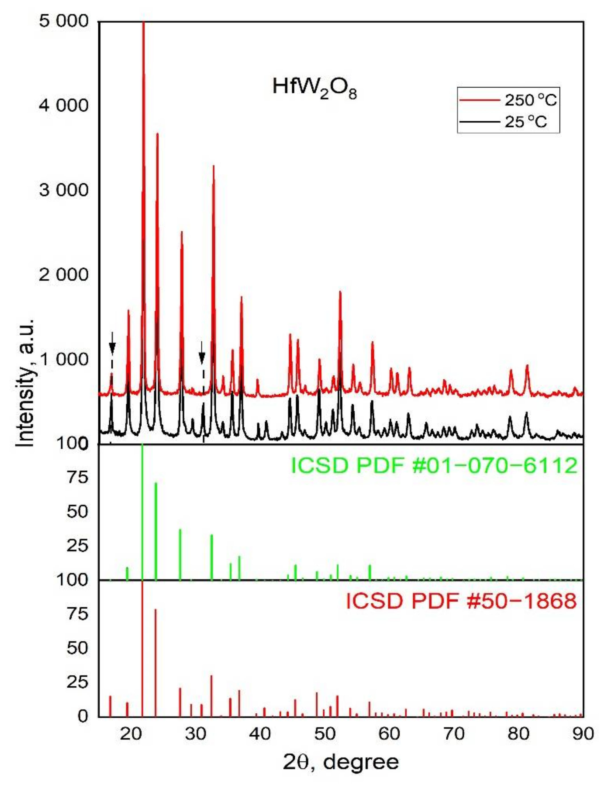
The structures of α-HfW2O8 and β-HfW2O8 were needed to evaluate the structure of the solid solutions. As long as our ICSD database did not contain .cif files of the α-HfW2O8 nor β-HfW2O8, we used the .cif file for α-ZrW2O8 (ICSD PDF #50-1868) to present the structure of α-HfW2O8, which is isostructural to α-HfW2O8. As for β-HfW2O8, the .cif file of ZrW0.977Mo1.023O8 (ICSD PDF #01-070-6112), which is isostructural to β-ZrW2O8 and β-HfW2O8, was used [22]. The diffractograms of the low-temperature phase (α-HfW2O8) and the high-temperature phase (β-HfW2O8) synthesized using the hydrothermal method along with mentioned ICSD data are shown in Figure 2. The starting structural parameters used for α-HfW2O8 and β-HfW2O8 are listed in Tables S1 and S2.

3.2. Characterization of the Solid Solutions Hf1−xLnxW2O8−x/2 by XRD; Raman and IR Spectroscopy—Homogeneity of the Samples; Influence of Ln3+

By introducing Ln3+ ions to the structure of HfW2O8 oxygen vacancies were generated, leading to the general formula of our solid solutions, i.e., Hf1−xLnxW2O8−x/2. It is widely accepted that O-vacancies introduced in this way are considered intrinsic, but we did not follow their evolution, nor did we have a way to measure them exactly. Essential to point out is that, during the Rietveld refinement, the occupancy of all O-atoms was refined, but, due to the very low concentration of these defects, we did not notice any major deviations.
The powder X-ray diffraction patterns of the solid solutions evidenced their crystalline nature. All diffractograms show the reflection peaks typical for HfW2O8. XRD patterns of the samples Hf1−xEuxW2O8−x/2, 0.01 ≤ x ≤ 0.15, recorded at 25 °C, are presented in Figure 3. The reflexes observed in the samples of Hf1−xEuxW2O8−x/2 with x = 0.09 and up to x = 0.15 indicate the formation of a secondary WO3 phase. Based on that, it can be stated that the samples of Hf1−xLnxW2O8−x/2 obtained were phase-homogeneous up to x = 0.07, as shown by the powder XRD patterns of Hf1−xEuxW2O8−x/2. Considering that, we focus our further research mainly on the solid solutions Hf1−xLnxW2O8−x/2 with x 0.01 and 0.05.
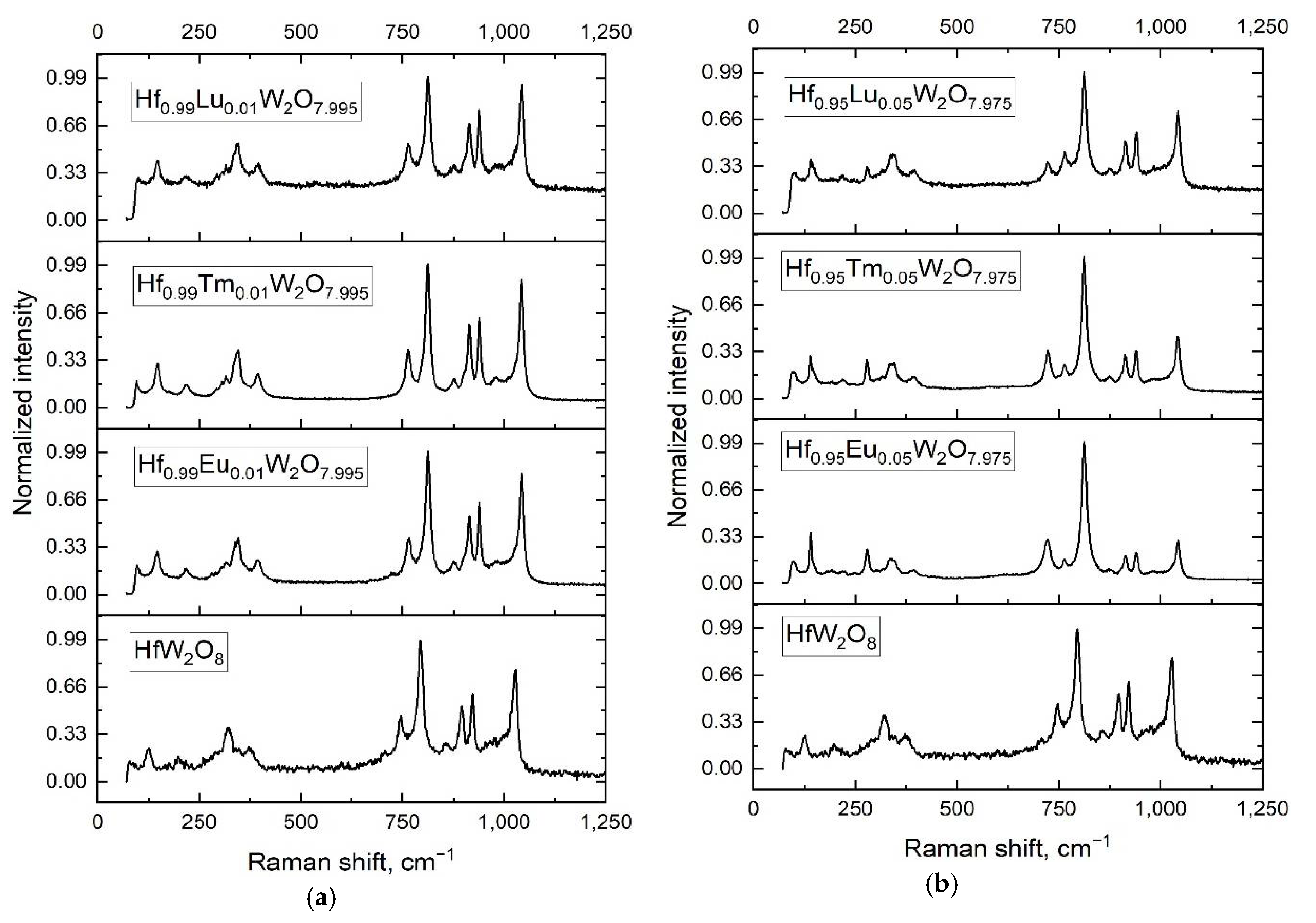
Taking into account that Raman spectroscopy is known as an effective and sensitive method to track the changes in the position of and bonding between the atoms of W and O in the crystal lattice [23], Raman spectra were recorded for the pure α-HfW2O8 and the solid solutions Hf1−xLnxW2O8−x/2, x = 0.01 and 0.05. The structure of α-HfW2O8 is viewed as a network of corner-sharing HfO6 octahedra and WO4 tetrahedra, and the Raman modes of tungstates are assigned as lattice modes, translation, vibrational, and internal modes of WO4 in the range of 100–1,100 cm−1 [24,25]. In the Raman spectrum of the pure α-HfW2O8 bands, low- and high-wavenumbers, in the range of 400–100 and 1,040–700 cm−1 are observed (Figure 4). The precise values of the bands position are listed in Table S3.
The Raman spectra interpretation was based on the literature data [26]. The modes centered at 1,026, 999, 921, 896, and 859 cm−1 can be assigned to the symmetric stretching vibrations vs. modes of the WO4; the modes of 796, 746 to the WO4 asymmetric stretching (vas modes); the one at 373.03 to the asymmetric bending, 345.9, 322.8; and 297.1 cm−1 to the symmetric bending modes. The bands at 199 and 125 cm−1 are regarded as originating from lattice modes.
In the Raman spectra of the solid solutions Hf1−xLnxW2O8−x/2, a shifting of bands toward higher wavenumbers, i.e., higher frequencies, is observed (Figure 4a,b). This shifting affects the bands assigned to the stretching vibrations of W−O−W bonds, νs(WO4), namely, 795.5 cm−1 (the most intensive one) and 745.9 cm−1 (the weaker one) of HfW2O8. Both bands are shifted to higher wavenumbers, i.e., 812–813 and 764–765 cm−1, respectively, in the solid solutions Hf1−xLnxW2O8−x/2, x = 0.01 and x = 0.05 (Figure 4a,b). Additionally, new bands at 721, 723, and 693 cm−1 were detected in the spectra of Hf0.95Ln0.05W2O8−x/2, Ln = Eu, Tm, and Lu, respectively. At the same time, the shifting of the band at 1,025.98 cm−1 for pure α-HfW2O8 toward the higher wavenumber of 1,043 cm−1 for Hf0.99Ln0.01W2O8−x/2 and Hf0.95Ln0.05W2O8−x/2 is clear evidence of the influence of Ln3+ on the crystal structure. Regarding the position of the band, the influence of Ln3+ is expressed by the essential decreasing of the intensity of the band in question, 1,043 cm−1, for the samples Hf0.95Ln0.05W2O8−x/2, i.e., the effect of the incorporation of the larger amount of Ln3+ is detected.
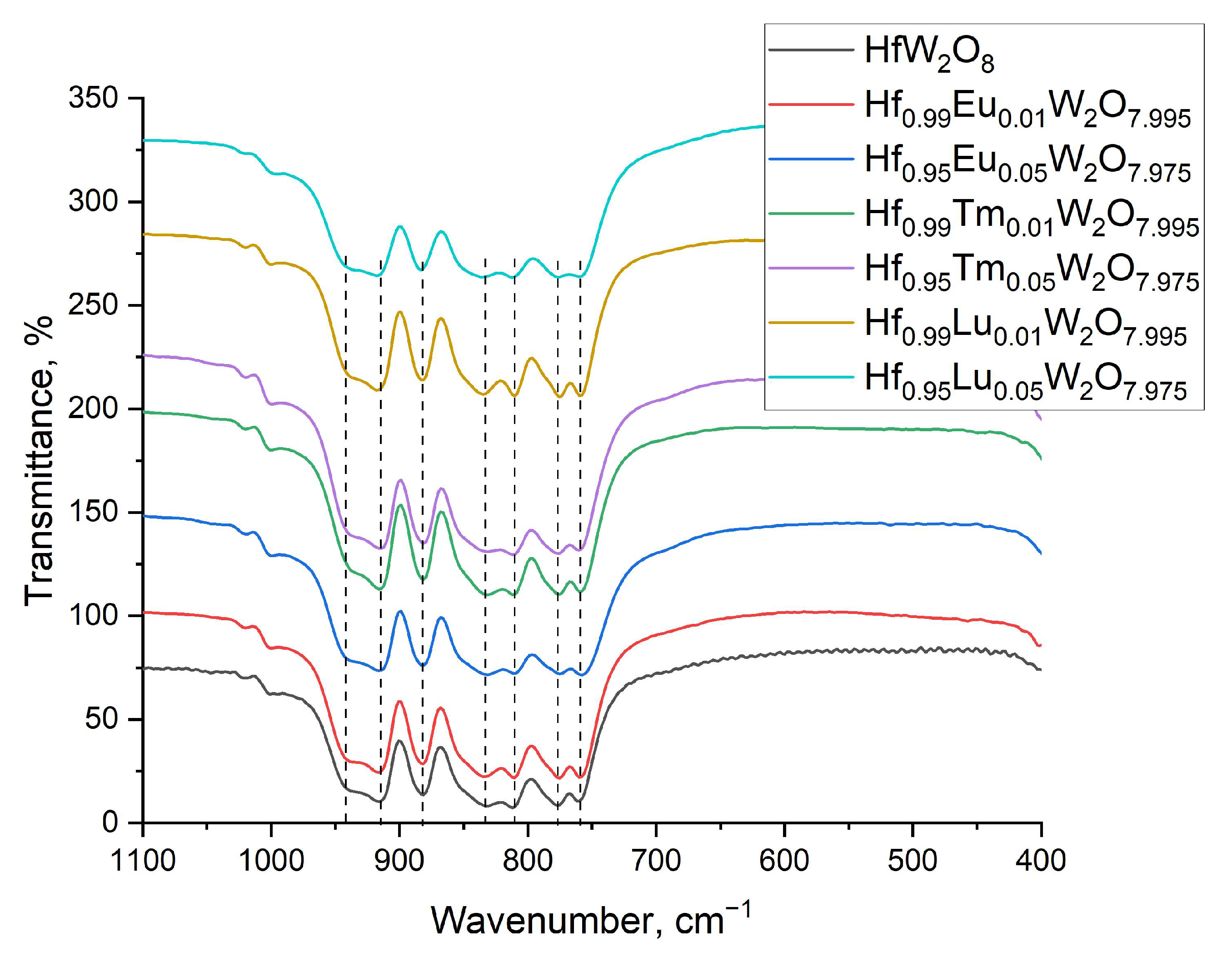
In addition to the Raman, infrared spectra of the samples were recorded in the range of 4,000–400 cm−1, with easily noticeable bands showing the presence of water (Figure S1). The more informative range of 1,100–400 cm−1, with the absorption bands of 941, 917, 882, 832, 809, 777, and 761 cm−1 accentuated with dashed lines, are shown in Figure 5.
The bands are caused by the symmetric (941, 917, 882, and 832 cm−1) and asymmetric stretching vibrations of W-O in WO4 tetrahedra (809, 777, and 761 cm−1) [26]. The asymmetric and symmetric bending, as well as the lattice modes, were below 400 cm−1, and so, they were not detected by the FT–IR equipment used. The influence of the Ln3+ doping is revealed in the spectrum of Hf0.95Lu0.05W2O8−x/2, where a broadening of the band at 761 cm−1 is visible, although slightly noticeable in the spectra of the other Hf0.95Ln0.05W2O8−x/2.

3.3. The Morphology of the Samples by Electron Microscopy, SEM, and TEM

The SEM micrographs exhibit similar needle-like crystals of HfW2O8 (Figure 6a) and of the solid solutions Hf0.99Eu0.01W2O8−x/2 and Hf0.095Eu0.05W2O8−x/2 (Figure 6b,c), proving that the morphology is not affected by Ln3+. SEM micrographs of the precursor HfW2O7(OH;Cl)2 and α-HfW2O8 verifying the method of α-HfW2O8 formation are shown in Figure S2.
The needle-like microcrystals, similar to those observed through SEM, were detected by TEM for α-HfW2O8 and the solid solutions; some more micrographs are included in the supplementary information (Figure S3). Well-formed microcrystals with high crystallinity are shown for Hf0.99Tm0.01W2O7.995 in Figure 7a. The lengths of the microcrystals vary in the range of 2 to 5 μm.
The lattice arrangements, clearly arranged crystalline planes and interplanar distances for the solid solutions Hf0.99Lu0.01W2O7.995, Hf0.99Eu0.01W2O7.995, and Hf0.95Eu0.05W2O7.975 are shown in Figure 7b–d.
The crystal plane alignments in the direction correspondent to the highest XRD diffraction peak in the cubic structure of α-HfW2O8 can be seen. The interplanar distances of the samples Hf0.95Eu0.05W2O7.975 and Hf0.99Lu0.01W2O7.995 (220) and (221) show increasing distances for Hf0.95Eu0.05W2O7.975, which is a result of the bigger ionic radius of Eu3+ (94.7 pm Eu3+; 86.1 pm Lu3+ [27]).

3.4. Phase Transition; Reversibility; and the Coefficients of Thermal Expansion in the Pure HfW2O8 and in the Solid Solutions Hf1−xLnxW2O8−x/2 (x = 0.01 and 0.05)

3.4.1. The Phase Transition α-HfW2O8 to β-HfW2O8 and its Reversibility

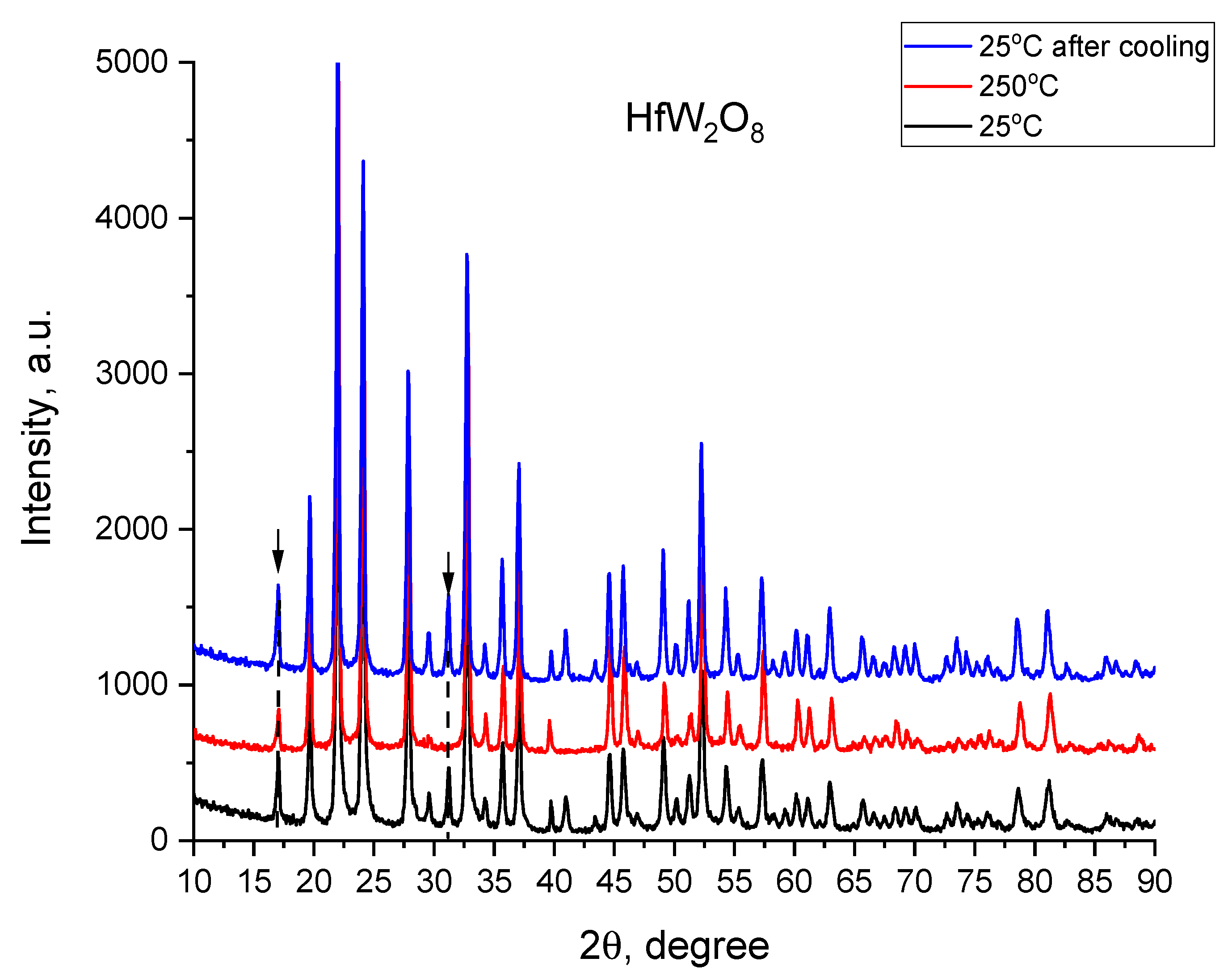
The X-Ray diffraction patterns recorded at 25/250/25 °C of pure HfW2O8 synthesized by hydrothermal method are presented in Figure 8, from them, the α-HfW2O8 ⇌ β-HfW2O8 transition and its reversibility follows. The reflex at 16.9 2Theta diminishes its intensity, while the intensity of the reflex at 31 2Theta diminishes and disappears with the temperature increase (indicated by arrows in Figure 8). As long as the latter two reflexes are typical for α-HfW2O8, their disappearance at 250 °C is a sign of the completed phase transition α-HfW2O8 → β-HfW2O8. After cooling down to 25 °C, these reflexes can be detected again as evidence for the reversibility of the transition (Figure 8).

3.4.2. Unit Cell Parameters and Coefficients of Thermal Expansion (CTE)

The unit cell parameters and the coefficients of thermal expansion (CTE) for pure HfW2O8 and Hf1−xLnxW2O8−x/2, x = 0.01 and 0.05, along with the coefficients of thermal expansion (CTE) calculated for the interval 25–100 °C (α-HfW2O8 phase) and 200–250 °C (β-HfW2O8 phase) and 25–250 °C are presented in Table 1.
Considering that HfW2O8 solid solutions have isotropic negative thermal expansion, we used the classical formula for linear expansion (instead of volume expansion) [14]
a = α a 298 T ,
where a is the change in the unit cell parameter, α is the linear coefficient of thermal expansion, a 298 is the unit cell parameter at room temperature, and T is the change in the temperature.
It can be seen that the cubic unit-cell parameter for pure HfW2O8 in fact diminishes with the temperature increase from 25 to 250 °C, proving that the cell shrinks and demonstrating the negative coefficient of thermal expansion. The same tendency is observed for the unit cell parameters of Hf0.99Ln0.01W2O8−x/2 and Hf0.95Ln0.05W2O8−x/2, upon the temperature increase (Table 1). When the Ln3+ content increases from x = 0.01 to x = 0.05, an influence on the unit cell parameters is observed; this influence is well pronounced for Eu3+, i.e., a slight decrease for the low-temperature phase α-Hf1−xLnxW2O8−x/2 (25 °C) and a slight increase for the high temperature phase β-Hf1−xLnxW2O8−x/2 (250 °C) (within the error range). In comparison with the pure HfW2O8, an increase of the cubic unit-cell parameter of Hf1−xLnxW2O8−x/2 is noticeable, especially for the Eu3+-containing samples (Table 1), as result of the bigger Eu3+ ion.
The coefficients of thermal expansion calculated were −10.22 and −1.10 × 10⁻⁶ K−1, for the pure α-HfW2O8 and β-HfW2O8 phases, respectively (Table 1). They differ from the literature data, −9 × 10⁻⁶K−1 and −6 × 10⁻⁶K−1 [11], quite likely as a result of the different method used for synthesis. The presence of Ln3+ in the solid solutions is essential for the α-HfW2O8 phase to effect an increase of CTE, and for β-HfW2O8 phase, to effect a decrease of CTE when a Ln3+ increase is observed. For the low temperature, the α-Hf1−xLnxW2O8−x/2 phase (25–100 °C) CTE increases with Ln3+ especially for Eu3+- and Tm3+-containing samples. The CTE values for the high-temperature phase β-Hf0.95Ln0.05W2O8−x/2 (200–250 °C) are lower than the value for the pure high-temperature β-HfW2O8 phase.
The high-temperature XRD values for Hf1−xLnxW2O8−x/2 (x = 0.01; Ln = Eu, Lu) show that the temperature of 140 °C is a critical temperature for the phase transition, i.e., the reflex at 31 2Theta, typical for α- HfW2O8, disappears there (Figure 9a,b).

3.4.3. Order-to-Disorder Phase Transition for Hf1−xLnxW2O8−x/2 (x = 0.01; 0.05) and the Role of Ln3+

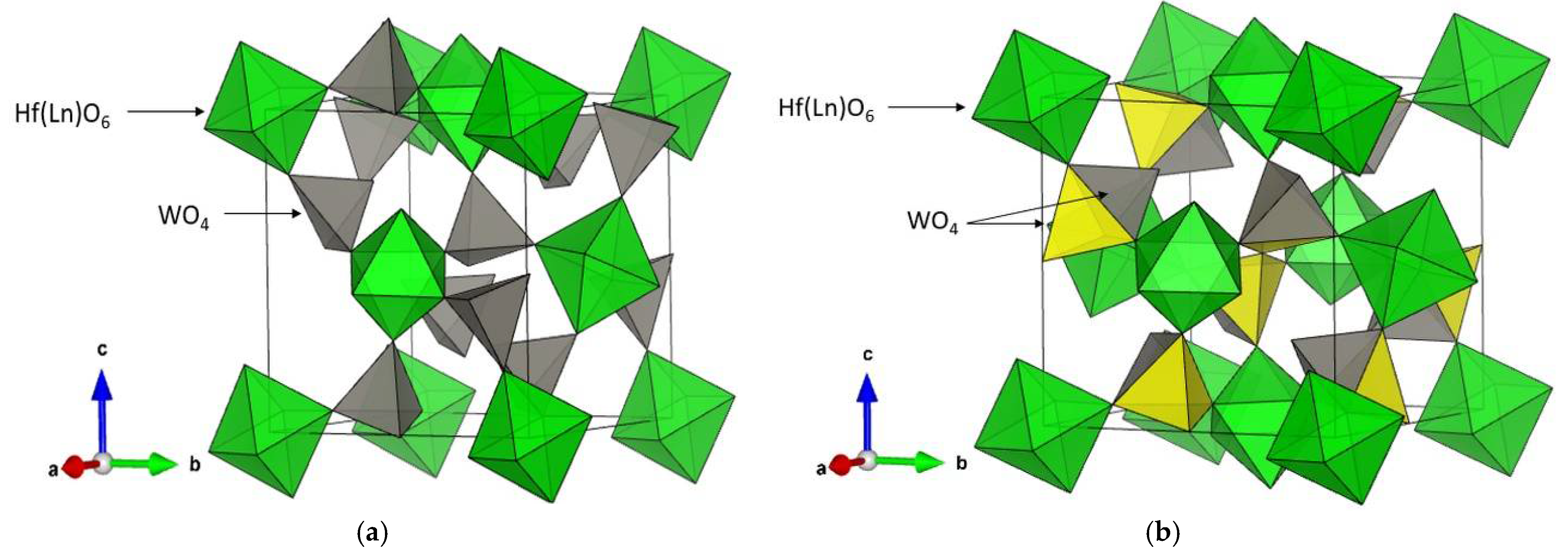
The structure of the low-temperature α-HfW2O8 and β-HfW2O8 phase has corner-sharing HfO6 octahedra and WO4 tetrahedra. The difference concerns the WO4 tetrahedra, namely, in the α-HfW2O8 phase, each WO4 tetrahedron shares three of its oxygen atoms with the adjacent octahedra, while, in the high-temperature β-HfW2O8 phase, two WO4 share three joined O atoms. The crystal structures of the low-temperature α-Hf1−xLnxW2O8−x/2 and the high-temperature β-Hf1−xLnxW2O8−x/2 are shown in Figure 10, where the half-filled WO4 in β- Hf1−xLnxW2O8−x/2 are accentuated by color.
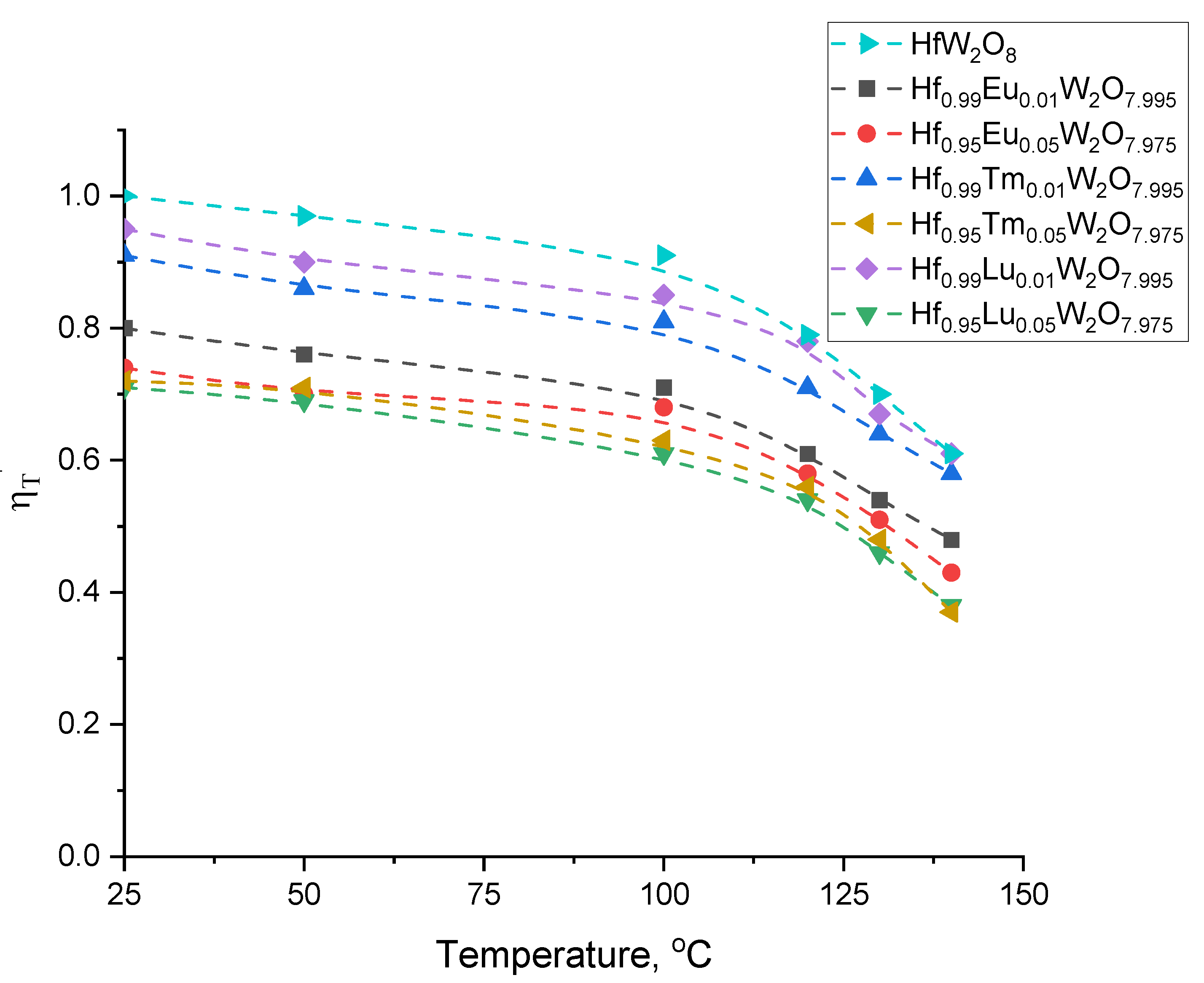
The orientations of the WO4 tetrahedra determine the transition pf α-HfW2O8 → β-HfW2O8, which is called order-to-disorder phase transition [8]. The extent of the WO4 tetrahedra disorder depending on the temperature can be evaluated by the parameter ηT’ [20], calculated by the following equation:
η T = [ ( I 310 I 210 ) ] T [ ( I 310 I 210 ) H f W 2 O 8 ] 298 K ,
where I310 and I210 are the integrated intensities of the reflections (310) and (210), respectively; the former indicates the ordered α-HfW2O8 phase, the latter does not changing during the phase transition. As can be seen in Figure 11, the relative order parameter at room temperature significantly decreases when Eu3+ is introduced to the system, leading to a higher degree of distortion in Hf0.99Eu0.01W2O8−x/2. The effect of Tm3+ and Lu3+ on Hf0.99Ln0.01W2O8−x/2 is less pronounced, and it can be explained by the degree of solid solubility of the heavier Ln3+, which is much more soluble in the system due to the smaller ionic radii in comparison with Hf4+ radius (Lu3+ 86.1, Tm3+ 88.0, Eu3+ 94.7, Hf4+ 71 pm, CN 6 [27]).

3.5. UV–Vis Absorption of the Solid Solutions and the Energy of the Band Gaps

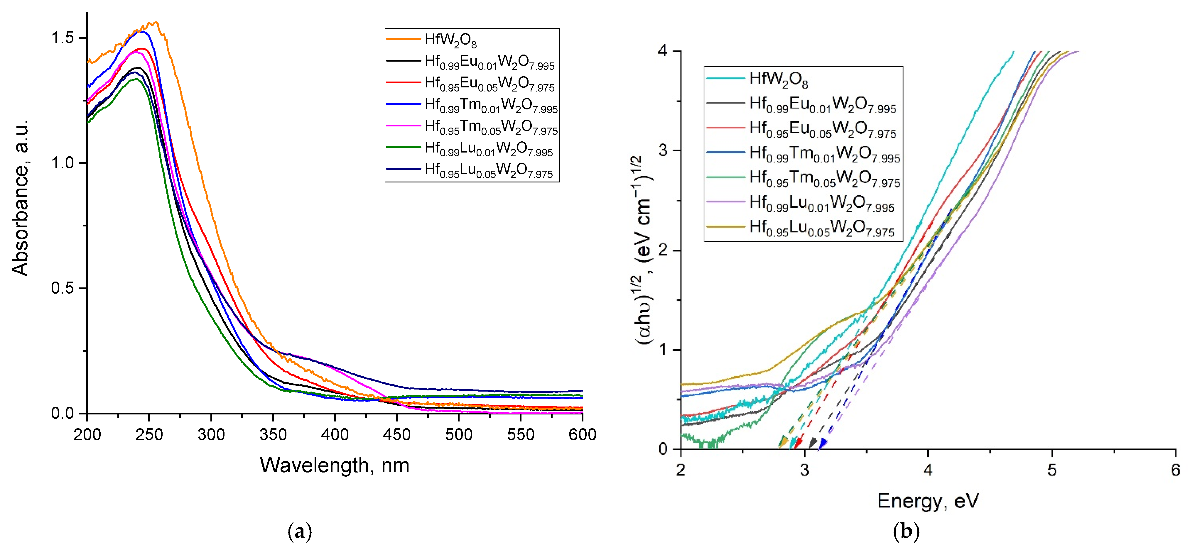
The absorbance in the UV–Vis range (200–450 nm) shows a clear maximum at approximately 250 nm for all samples. A weak absorbance at approximately 400 nm differs Hf1−xTmxW2O8 (x = 0.01 and 0.05) from the other samples (Figure 12a). It is quite likely that the bands between 250 and 350 nm exist due to the strong ligand-to-metal charge transfer observed both in slightly distorted monotungstate structures and polytungstates [28].
Band-gap-energy calculations were accomplished based on UV–Vis data (Figure 12a,b) and listed in Table 2. The UV–Vis data were analyzed to determine the relationship among the optical band gap, absorption coefficient, and energy (hν) of the incident photon for near-edge optical absorption. The calculations were performed from the measured curves by fits according to Tauc’s equation [29]; i.e., αhν = A(hν − Eg)n, where A is a constant independent of hν, Eg is the band gap, and n depends on the type of transition. In addition, the well-known approach for Eg determination from the intersection of the linear fits of (αhν)1/n versus hv on the x-axis was used, n being 1/2 and 2 for direct and indirect band gaps, respectively.
The band gap value of the pure α-HfW2O8, 2.87 eV, obtained by the Tauc’s equation corresponds well to the value observed by Ouyang for pure α-ZrW2O8, 2.84 eV [30]. The values of the solid solutions for all samples of the type Hf0.99Ln0.01W2O8−x/2 increased in the range of 3.02, 3.10, and 3.12 eV, for Eu3+, Tm3+, and Lu3+, respectively. This can be attributed to the decrease of the crystallites due to the presence of Ln3+ [31]. Interestingly, the further incorporation of Ln3+ for Hf0.95Ln0.05W2O8−x/2 leads to the significant narrowing of the band gap, especially for Tm3+ and Lu3+ (2.78 eV), most likely due to the increased order of distortion of the WO4 polyhedra. A similar effect was observed by Muthu and coauthors [32] due to pressure induced amorphization.

4. Conclusions

Using the hydrothermal method, pure HfW2O8- and Ln3+-containing homogeneous solid solutions Hf1−xLnxW2O8−x/2 (x = 0.01, 0.05; Ln = Eu, Tm, Lu) were obtained and characterized by XRD, Raman, FT–IR spectroscopy, and electron microscopy. The influence of Ln3+ was detected by (i) the Raman spectra shifting to the higher wavenumbers of the most intensive bands of Hf1−xLnxW2O8−x/2; (ii) the unit cell parameters decreasing with the temperature for the solid solutions Hf1−xLnxW2O8−x/2 in connection with the isotropic negative thermal expansion; (iii) the observed increase of CTE for the α-HfW2O8 phase and the decrease of CTE for the β-HfW2O8 phase, with a Ln3+ increase; (iv) the increased energy-band-gap values of the solid solutions Hf0.99Ln0.01W2O8−x/2 with decreases in the atomic radii of Eu3+, Tm3+, and Lu3+; and (v) the significant narrowing of the band gap for Hf0.95Ln0.05W2O8−x/2 (Ln = Tm3+ and Lu3+) due to the increased order of distortion of the WO4 polyhedra.
The question for the potential incorporation of Ln3+ into the structure of the tungstates is interesting taking into account the options for the potential position of the Ln3+, i.e., either in the interstices or on the surface or by replacing the Hf4+ ions in the HfO6 octahedra. This is challenging due to the fact that hafnium and lanthanides possess different atomic and ionic radii, complicating the replacement of Hf+4/Ln3+. On the other hand, the differences between the typical oxidation states of lanthanides and hafnium, +3 and +4, respectively, leads to the question of the neutrality of the charge of the solid solutions formed, which makes it important to follow the oxygen vacancies. In spite of the Rietveld refinement of the occupancy of all oxygen atoms, due to the very low concentration of defects, major deviations were not detected.

Supplementary Materials

The following supporting information can be downloaded at: https://www.mdpi.com/article/10.3390/cryst12030327/s1, Figure S1: FT–IR spectra of the samples in the range of 4000–400 cm−1; Figure S2: TEM micrographs; Figure S3: SEM micrographs; Table S1: Starting structural parameters for α-HfW2O8; Table S2: Parameters for the starting model for β-HfW2O8, based on [22]; Table S3: Raman spectra of HW2O8 and Hf1−xLnxW2O8−x/2 (x = 0.01 and 0.05): values of the bands position of the samples.

Author Contributions

Conceptualization, M.T. and M.M.; methodology, M.T.; software, M.T.; validation, M.T. and M.N.; formal analysis, M.T. and E.V.; investigation, M.T.; resources, M.T.; writing–original draft preparation, M.M. and M.T.; writing–review and editing, M.M. and M.T.; supervision, M.T.; project administration, M.T. All authors have read and agreed to the published version of the manuscript.

Funding

Bulgarian Fund for Scientific Investigations, project DM 19/5; European Regional Development Fund within the Operational Programme “Science and Education for Smart Growth 2014–2020” under the Project CoE “National Center of Mechatronics and Clean Technologies“ BG05M2OP001-1.001-0008-C01.

Institutional Review Board Statement

Not applicable.

Informed Consent Statement

Not applicable.

Data Availability Statement

Not applicable.

Acknowledgments

The financial support from the Bulgarian Fund for Scientific Investigations, project DM 19/5 from 2017 is highly acknowledged. E.V. acknowledges the support of the European Regional Development Fund within the Operational Programme “Science and Education for Smart Growth 2014–2020” under the Project CoE “National Center of Mechatronics and Clean Technologies“ BG05M2OP001-1.001-0008-C01.

Conflicts of Interest

The authors declare no conflict of interest.

References

  1. Takenaka, K. Negative thermal expansion materials: Technological key for control of thermal expansion. Sci. Technol. Adv. Mater. 2012, 13, 013001. [Google Scholar] [CrossRef] [PubMed]
  2. Lind, C. Two decades of negative thermal expansion research: Where do we stand? Materials 2012, 5, 1125–1154. [Google Scholar] [CrossRef] [PubMed]
  3. Sanson, A.; Chen, J. Towards the control of thermal expansion: From 1996 to today. Front. Chem. 2019, 7, 284. [Google Scholar] [CrossRef] [PubMed]
  4. Evans, D.L.; Fischer, G.R.; Geiger, J.E.; Martin, F.W. Thermal expansions and chemical modifications of cordierite. J. Am. Ceram. Soc. 1980, 63, 629–634. [Google Scholar] [CrossRef]
  5. Phillips, A.E.; Goodwin, A.L.; Halder, G.J.; Southon, P.D.; Kepert, C.J. Nanoporosity and exceptional negative thermal expansion in single-network cadmium cyanide. Angew. Chem. 2008, 120, 1418–1421. [Google Scholar] [CrossRef]
  6. Azuma, M.; Chen, W.-T.; Seki, H.; Czapski, M.; Smirnova, O.; Oka, K.; Mizumaki, M.; Watanuki, T.; Ishimatsu, N.; Kawamura, N.; et al. Colossal negative thermal expansion in BiNiO3 induced by intermetallic charge transfer. Nat. Commun. 2011, 2, 347. [Google Scholar] [CrossRef] [Green Version]
  7. Shi, N.; Song, Y.; Xing, X.; Chen, J. Negative thermal expansion in framework structure materials. Coord. Chem. Rev. 2021, 449, 214204. [Google Scholar] [CrossRef]
  8. Evans, J.S.; Mary, T.A.; Vogt, T.; Subramanian, M.A.; Sleight, A.W. Negative thermal expansion in ZrW2O8 and HfW2O8. Chem. Mater. 1996, 8, 2809–2823. [Google Scholar] [CrossRef]
  9. Evans, J.S.O.; David, W.I.F.; Sleight, A.W. Structural investigation of the negative thermal expansion material ZrW2O8. Acta Cryst. 1999, B55, 333–340. [Google Scholar] [CrossRef]
  10. Mary, T.A.; Evans, J.S.O.; Vogt, T.; Sleight, A.W. Negative thermal expansion from 0.3 to 1050 Kelvin in ZrW2O8. Science 1996, 272, 90–92. [Google Scholar] [CrossRef] [Green Version]
  11. Gallington, L.C.; Chapman, K.W.; Morelock, C.R.; Chupas, P.J.; Wilkinson, A.P. Dramatic softening of the negative thermal expansion material HfW2O8 upon heating through its WO4 orientational order-disorder phase transition. J. Appl. Phys. 2014, 115, 053512. [Google Scholar] [CrossRef]
  12. Yamamura, Y.; Nakajima, N.; Tsuji, T. Calorimetric and X-ray diffraction studies of a-to-b structural phase transitions in HfW2O8 and ZrW2O8. Phys. Rev. B 2001, 64, 184109. [Google Scholar] [CrossRef]
  13. Yamamura, Y.; Nakajima, N.; Tsuji, T.; Koyano, M.; Iwasa, Y.; Saito, K.; Sorai, M. Heat capacity and Gruneisen function of negative thermal expansion compound HfW2O8. Solid State Commun. 2002, 121, 213–217. [Google Scholar] [CrossRef]
  14. Encheva, E.D.; Nedyalkov, M.K.; Tsvetkov, M.P.; Milanova, M.M. The influence of the modification of zirconium tungstate with Eu(III) on the α→β phase transition temperature and optical band gap. Bulg. Chem. Comm. Spec. Issue F 2018, 50, 143–149. [Google Scholar]
  15. De Meyer, C.; Bouree, F.; Evans, J.S.O.; de Buysser, K.; Bruneel, E.; van Driessche, I.; Hoste, S. Structure and phase transition of Sn-substituted Zr1−xSnxW2O8. J. Mater. Chem. 2004, 14, 2988–2994. [Google Scholar] [CrossRef]
  16. De Buysser, K.; van Driessche, I.; Putte, B.V.; Vanhee, P.; Schaubroeck, J.; Hoste, S. Study of negative thermal expansion and shift in phase transition temperature in Ti4+- and Sn4+-substituted ZrW2O8 materials. Inorg. Chem. 2008, 47, 736–741. [Google Scholar] [CrossRef] [Green Version]
  17. Yamamura, Y.; Masago, K.; Kato, M.; Tsuji, T. Comprehensive interpretation of a substitution effect on an order-disorder phase transition in A1−xMxW2O8−y (A = Zr, Hf; M = trivalent cations) and other ZrW2O8-based solid solutions. J. Phys. Chem. B 2007, 111, 10118–10122. [Google Scholar] [CrossRef] [PubMed]
  18. Yamamura, Y.; Nakajima, N.; Tsuji, T.; Kojima, A.; Kuroiwa, Y.; Sawada, A.; Aoyagi, S.; Kasatani, H. Drastic lowering of the order-disorder phase transition temperatures in Zr1−xMxW2O8−y (M = Sc, Y, In) solid solutions. Phys. Rev. B 2004, 70, 104107. [Google Scholar] [CrossRef]
  19. Nakajima, N.; Yamamura, Y.; Tsuji, T. Synthesis and physical properties of negative thermal expansion materials Zr1−xMxW2O8−y (M = Sc, In, Y) substituted for Zr(IV) sites by M(III) ions. Solid State Commun. 2003, 128, 193–196. [Google Scholar] [CrossRef]
  20. Li, H.-H.; Han, J.-S.; Ma, H.; Huang, L.; Zhao, X.-H. Zr1−xLnxW2O8−x/2 (Ln = Eu, Er, Yb): Solid solutions of negative thermal expansion-synthesis, characterization and limited solid solubility. J. Solid State Chem. 2007, 180, 852–857. [Google Scholar] [CrossRef]
  21. Rodriguez-Carvajal, J. Recent developments of the program fullprof. In Newsletter in Commission on Powder Diffraction; IUCr: Chester, UK, 2001; Volume 26, pp. 12–19. [Google Scholar]
  22. Kameswari, U.; Sleight, A.W.; Evans, J.S. Rapid synthesis of ZrW2O8 and related phases, and structure refinement of ZrWMoO8. Int. J. Inorg. Mater. 2000, 2, 333–337. [Google Scholar] [CrossRef]
  23. Thummavichai, K.; Wang, N.; Xu, F.; Rance, G.; Xia, Y.; Zhu, Y. In situ investigations of the phase change behavior of tungsten oxide nanostructures. R. Soc. Open Sci. 2018, 5, 171932. [Google Scholar] [CrossRef] [PubMed] [Green Version]
  24. Yamamura, Y.; Nakajima, N.; Tsuji, T.; Koyano, M.; Iwasa, Y.; Katayama, S.; Saito, K.; Sorai, M. Low-temperature heat capacities and Raman spectra of negative thermal expansion compounds ZrW2O8 and HfW2O8. Phys. Rev. B 2002, 66, 014301. [Google Scholar] [CrossRef]
  25. Jorgensen, J.D.; Hu, Z.; Shor, S.; Sleight, A.W.; Evans, J.S.O. Pressure-induced cubic-to-orthorhombic phase transformation in the negative thermal expansion material HfW2O8. J. Appl. Phys. 2001, 89, 3184–3188. [Google Scholar] [CrossRef]
  26. Chen, B.; Muthu, D.V.S.; Liu, Z.X.; Sleight, A.W.; Kruger, M.B. High-pressure Raman and infrared study of HfW2O8. Phys. Rev. B 2001, 64, 214111. [Google Scholar] [CrossRef]
  27. Shannon, R.D. Revised effective ionic radii and systematic studies of interatomic distances in halides and chalcogenides. Acta Cryst. 1976, A32, 751–767. [Google Scholar] [CrossRef]
  28. Ross-Medgaarden, E.I.; Wachs, E.I. Structural determination of bulk and surface tungsten oxides with UV-vis diffuse reflectance spectroscopy and Raman spectroscopy. J. Phys. Chem. C 2007, 111, 15089–15099. [Google Scholar] [CrossRef]
  29. Tauc, J.; Grigorovici, R.; Vancu, A. Optical properties and electronic structure of amorphous germanium. Phys. Status Solidi B 1966, 15, 627–637. [Google Scholar] [CrossRef]
  30. Ouyang, L.; Xu, Y.-N.; Ching, W.Y. Electronic structure of cubic and orthorhombic phases of ZrW2O8. Phys. Rev. B 2002, 65, 113110. [Google Scholar] [CrossRef]
  31. Church, J.S.; Cant, N.W.; Trimm, D.L. Stabilisation of aluminas by rare earth and alkaline earth ions. Appl. Catal. 1993, 101, 105. [Google Scholar] [CrossRef]
  32. Muthu, D.V.S.; Chen, B.; Sleight, A.W.; Wrobel, J.M.; Kruger, M.B. ZrW2O8 and HfW2O8: Band gap shifts under pressure. Solid State Commun. 2002, 122, 25–28. [Google Scholar] [CrossRef]
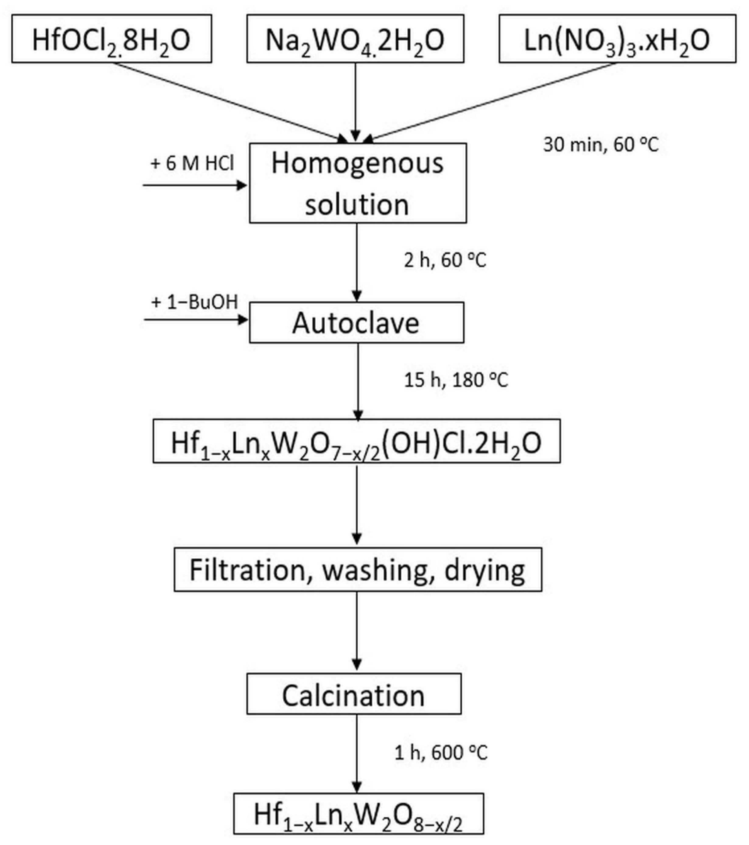
Figure 1. Typical synthesis steps.
Crystals 12 00327 g001
Figure 2. The comparison of XRD data for the synthesized α-HfW2O8 and β-HfW2O8 (top) with the analogues of the ICSD data for α-ZrW2O8 (bottom), ZrW0.977Mo1.023O8 (middle).
Crystals 12 00327 g002
Figure 3. XRD patterns of the solid solutions Hf1−xEuxW2O8−x/2, 0.01 ≤ x ≤ 0.15, recorded at 25 °C.
Crystals 12 00327 g003
Figure 4. Raman spectra of HW2O8 and Hf1−xLnxW2O8−x/2, (a) x = 0.01 and (b) x = 0.05.
Crystals 12 00327 g004
Figure 5. FT–IR spectra of the samples in the range of 1100–400 cm−1.
Crystals 12 00327 g005
Figure 6. SEM micrographs of (a) HfW2O8, (b) Hf0.99Eu0.01W2O7.995, and (c) Hf0.095Eu0.05W2O7.975.
Crystals 12 00327 g006
Figure 7. TEM micrographs for (a) microcrystals of Hf0.99Tm0.01W2O7.995 with well-defined edges, (b) Hf0.99Lu0.01W2O7.995, (c) Hf0.99Eu0.01W2O7.995, and (d) Hf0.95Eu0.05W2O7.975 showing the internal crystalline structure with characteristic interplanar distances.
Crystals 12 00327 g007
Figure 8. XRD of pure HfW2O8, recorded at 25/250/25 °C (from bottom to top), demonstrating the reversibility of the α-HfW2O8 ⇌ β-HfW2O8 transition. The reflexes at 16.9 and 31.1 2Theta are indicated.
Crystals 12 00327 g008
Figure 9. High temperature XRD for Hf1−xLnxW2O8−x/2, x = 0.01; Ln (a) Eu, (b) Lu. The temperature of 140 °C is the critical temperature of the phase transition.
Crystals 12 00327 g009
Figure 10. Crystal structures of (a) α-Hf1−xLnxW2O8−x/2 and (b) β-Hf1−xLnxW2O8−x/2. The yellow and grey tetrahedra in β- Hf1−xLnxW2O8−x/2 represent the half-filled WO4.
Crystals 12 00327 g010
Figure 11. Influence of the temperature and amount of Ln(III) in the solid solutions Hf1−xLnxW2O8−x/2 (x = 0.01 and 0.05) on WO4 tetrahedra disorder.
Crystals 12 00327 g011
Figure 12. (a) UV–Vis spectra and (b) Energy of the band gap.
Crystals 12 00327 g012
Table 1. Unit cell parameters and CTE for pure HfW2O8 and Hf1−xLnxW2O8−x/2 (x = 0.01 and 0.05).
T °CHfW2O8Hf1−xEuxW2O8−x/2Hf1−xTmxW2O8−x/2Hf1−xLuxW2O8−x/2
x = 0.01x = 0.05x = 0.01x = 0.05x = 0.01x = 0.05
Unit cell
parameters,
Å
25 9.1244(2)9.1246(3)9.1245(1)9.1245(1)9.1245(1)9.1244(1)9.1243(1)
100 9.1174(1) 9.1179(1)9.1177(1)9.1171(1)9.1170(1)9.1173(1)9.1172(1)
200 9.1055(1)9.1058(2)9.1057(1)9.1050(3)9.1049(1)9.1049(1)9.1048(1)
250 9.1050(1) 9.1051(1)9.1053(2)9.1044(1)9.1046(1)9.1044(1)9.1045(2)
CTE,
×10−6 K−1
25–100 −10.22 −9.79−9.94−10.81−10.96−10.38−10.36
200–250 −1.10−1.54−0.87−1.32−0.66−1.10−0.66
25–250−9.45−9.49−9.35−9.79−9.69−9.74−9.64
Table 2. Energy band gap of the samples, eV.
SampleBand Gap Eg, eV
1α-HfW2O82.87
2α-ZrW2O82.84 [31]
3Hf0.99Eu0.01W2O7,9953.02
4Hf0.95Eu0.05W2O7.9752.92
5Hf0.99Tm0.01W2O7.9953.10
6Hf0.95Tm0.05W2O7.9752.78
7Hf0.99Lu0.01W2O7.9953.12
8Hf0.95Lu0.05W2O7.9752.78
Publisher’s Note: MDPI stays neutral with regard to jurisdictional claims in published maps and institutional affiliations.