Article

High-Efficiency Plasmonic Lens Based on Archimedes-Spiral with Cross Section of an Asymmetric Slot

1
Engineering Research Center of Optical Instrument and System, Ministry of Education and Shanghai Key Laboratory of Modern Optical System, University of Shanghai for Science and Technology, Shanghai 200093, China
2
School of Information Engineering, Jiangxi University of Science and Technology, Ganzhou 341000, China
*
Author to whom correspondence should be addressed.
Crystals 2022, 12(3), 316; https://doi.org/10.3390/cryst12030316
Submission received: 10 January 2022 / Revised: 3 February 2022 / Accepted: 21 February 2022 / Published: 24 February 2022
(This article belongs to the Section Materials for Energy Applications)

Abstract

:
A high-efficiency plasmonic lens composed of a single Archimedes-spiral slot with a cross section of an asymmetric slot is proposed. By adding an auxiliary nanocavity under the primary spiral slot, unidirectional plasmonic waves can be efficiently transmitted in the inward direction and focused on a hot spot in the center. Due to the asymmetric slot, the finite-difference time-domain (FDTD) method is used to numerically optimize the geometric parameters of the single spiral slot, which can achieve high-intensity unidirectional inward focusing. The proposed structure can decrease background noises and prevent cross-talk of nearby components in optical networks, which significantly improves the integration level of nanophotonic circuits and devices.

1. Introduction

Surface plasmonic lenses caused by surface plasmon polaritons (SPPs) are characterized by good confinement and high field intensity, which have aroused wide interest in the fields of super-resolution imaging [1,2,3,4], nanolithography [5,6], optical trapping [7,8,9,10] and biosensing [11,12]. Many schemes have been proposed to confine and focus surface plasmon polaritons to form a nanoscale hot spot. To obtain a high intensity of the hot spot, a variety of surface plasmonic lenses have been designed [13,14,15,16,17,18,19,20,21,22,23,24,25,26,27,28,29,30,31,32]. A previous study has shown that SPPs can be focused using a surface plasmonic lens consisting of a single annular slit [33]. However, the intensity of such a hot spot is not very high because the SPPs propagating outward from the single annular slit are not utilized [34]. A circular periodic grating structure surrounding the annular slit was introduced to generate resonance and reflect the outward propagating SPPs, enhancing the intensity at the focal point [35,36]. A single annular ring composed of an asymmetric slot with unidirectional excitation of plasmonic waves was also adopted to enhance the intensity at the focal point [37]. Another structure consisting of an Archimedes-spiral slot was demonstrated as an in-plane focusing element [38]. Similarly, outward propagating surface plasmon polaritons from the single spiral slot do not contribute to the nanofocusing of highly confined lights. To eliminate outward propagating SPPs, an asymmetric plasmonic nanoslit was employed to create a spiral plasmonic lens, and a high-intensity focusing hot spot was formed in the center of the lens [39].
We noted that directional excitation of surface plasmon polaritons can be acquired by adding an auxiliary resonant structure to a single nanoslot [40]. Based on this directional excitation nanoslot structure, we proposed and theoretically optimized a simplified and compact plasmonic lens consisting of only an Archimedes spiral with a cross-section of an asymmetric slot. The influences of the Archimedes-spiral structure and incident light on the electromagnetic field distribution in the focus area are analyzed and explained in this paper. Our lens can only emit plasmonic waves in the inward direction, eliminating strong background noises and avoiding inter-coupling between nearby components. This advantage is of great significance for future upgraded nanophotonic chips.

2. Materials and Methods

The designed structure is a single Archimedes-spiral asymmetric nanoslot, as illustrated in Figure 1. Firstly, a thin silver layer was deposited on a quartz substrate, and then a spiral slot with a cross-section consisting of a primary metal-insulator-metal (MIM) slot and an auxiliary resonant nanocavity were structured in the layer. The inner boundary of the spiral slot is given by the following equation:
r ( θ ) = r 0 + m λ S P P 2 π θ ,
where the parameter m represents the spiraling of the slot, and r and θ are the cylindrical coordinates. Figure 1a is a schematic view of a cross-section of our plasmonic lens. w1 and w2 are the widths of the primary and auxiliary spiral slots, respectively. h1 and h2 represent the depths of the primary and auxiliary slots. r 0 and r ( π ) are the inner radii of the spiral slot, where θ = 0 and π , respectively, as shown in the figure. The top view of the lens structure is illustrated in Figure 1b. The light we used to excite the propagating SPPs on the surface plasmonic lens was a circularly or linearly polarized light with normal incidence from the top of the silver film.
The primary spiral slot can be regarded as a subwavelength MIM gap waveguide. Surface plasmonic modes exist in this MIM gap waveguide. These modes can be divided into the following two sets: one with odd symmetry of Ez, which we called anti-symmetric mode; the other with even symmetry of Ez, which we called symmetric mode. The SPPs’ mode can be excited when a normal incident beam illuminates the gap waveguide. With the aid of the auxiliary spiral slot, unidirectional excitation of surface plasmon polaritons is obtained due to interference between the symmetric and the anti-symmetric modes in the primary slot. The plasmonic waves from the spiral nanoslot propagate unidirectionally inward to the center and interfere constructively or destructively with the optimized design of specific geometrical parameters. Therefore, a highly efficient focusing hot or a dark spot is formed in the center of the plasmonic lens.
Different from the scheme in ref. 39, we used an asymmetric slot instead of an asymmetric slit. Meanwhile, our lens was a plasmonic reflective lens. The incident light normally impinges on the top of the lens. The unidirectional plasmonic excitation underlying physical mechanism is different from that in ref. 39 (see ref. 37). Moreover, the SPPs’ excitation efficiency of our lens is much higher because of the SPPs reflection back from the bottom of the primary slot and the SPPs constructive interference in the top of the primary slot, so higher intensity SPPs and hot spots can be achieved in our scheme.

3. Results and Discussion

3.1. Unidirectional Excitation of SPPs with a 2D Asymmetric Slot

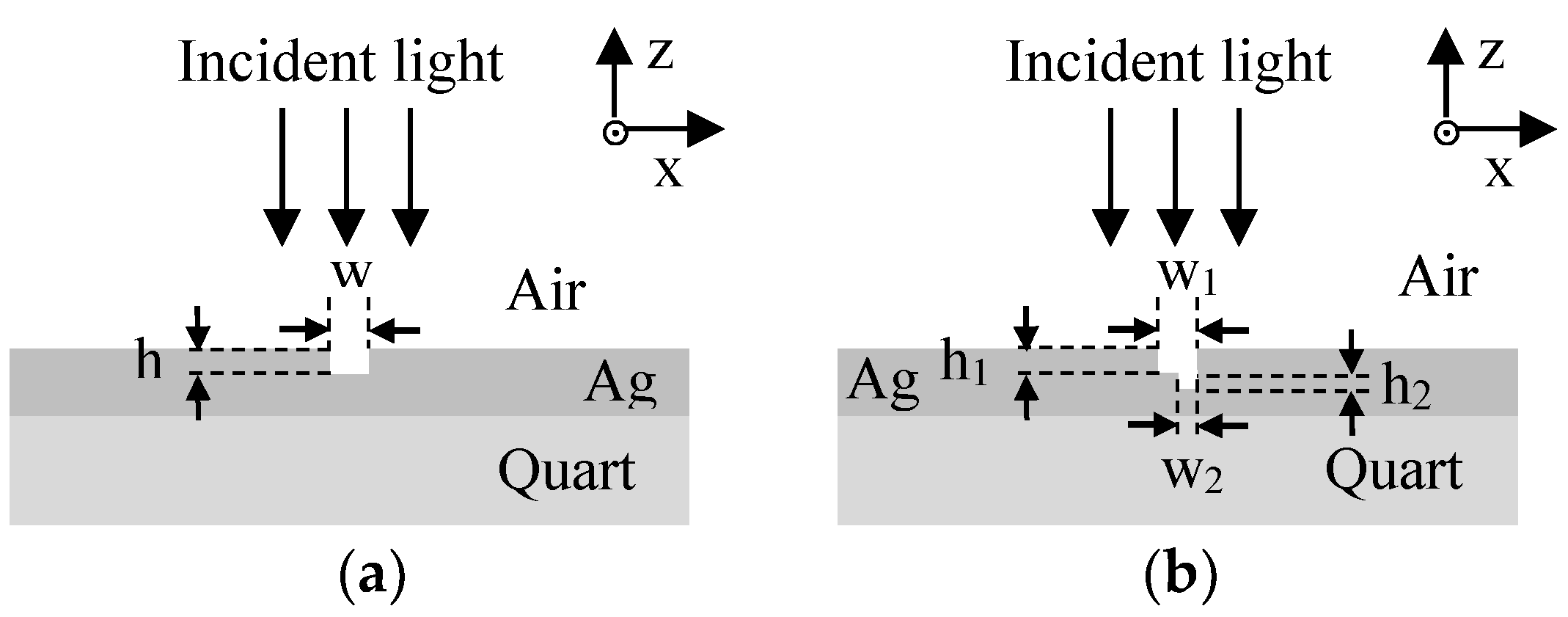
To obtain a high excitation efficiency for plasmonic nanofocusing with the above-mentioned structure in Figure 1, we first investigated the excitation of plasmonic waves along the Ag/air surface with a well-known traditional 2D symmetric MIM slot, as shown as Figure 2a. Afterwards, we examined the properties of unidirectional excitation for SPPs in a 2D asymmetric slot with a cross-section of a primary MIM slot and an auxiliary resonant nanocavity, as shown in Figure 2b. Finally, the nanofocusing behavior of the 3D spiral slot in Figure 1 was studied, for which the cross-section is shown in Figure 1a. Simulations were performed by using commercial software Lumerical Solutions (FDTD). The permittivity of the silver was −18.359 + 0.479i at a wavelength of λ = 633 nm, for which we took Johnson and Christy’s measurements as a reference [41].
In Figure 2a, the excitation light with its polarization direction along the x-direction normally impinged on the top of the Ag film in our FDTD simulations. The excitation light wavelength was set to λ = 633 nm. The width of the slot w was fixed to 310 nm. It was found that the excitation efficiency of the left or right propagating plasmonic waves from the MIM slot reached its maximum periodically with an increase in the depth h. We set the depth of h to 120 nm, and the excitation efficiency reached the first peak value.
An auxiliary nanocavity was added to the primary MIM slot for the unidirectional plasmonic excitation, as shown in Figure 2b. By carefully regulating amplitudes and phases of different plasmonic modes in the primary MIM slot, the unidirectional plasmonic excitation on the silver/air interface could be achieved. The values w1 and w2 were set to 310   nm and 155   nm . The critical parameters h1 and h2 were optimized in our FDTD simulations, and it was found that a highly efficient unidirectional excitation of plasmonic waves in the right direction is obtained when h1 = 110 nm and h2 = 40 nm.

3.2. Analysis of the Plasmonic Lens Based on Spiral Slot Illuminated by a Circularly Polarized Beam

Based on the above analysis, a surface plasmonic lens was designed on a silver film by adding an auxiliary spiral slot to a primary subwavelength spiral slot, as shown in Figure 1. The optimal geometry parameters of w 1 = 310   nm , w 2 = 155   nm , h 1 = 110   nm , and h 2 = 45   nm were used. The inner radius of the primary and the auxiliary spiral slots were r 0 = 2000   nm where θ = 0.
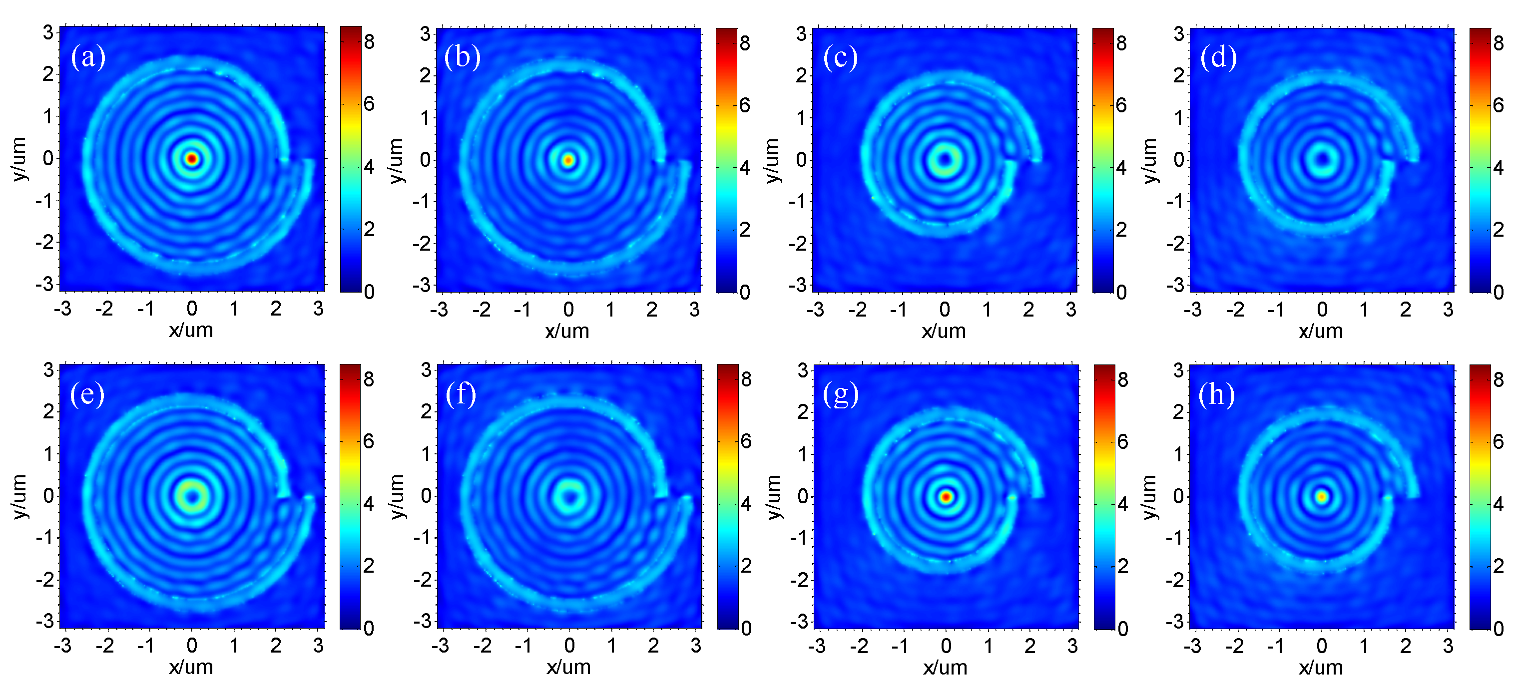
Figure 3 shows the electric field distribution |E| on the top surface of our plasmonic lens with different structures. The lens was illuminated by a circularly polarized beam (including left-circularly and right-circularly polarized light, λ = 633 nm) with normal incidence from the top of the silver film. The permittivity of the silver was −18.359 + 0.479i at the wavelength of λ = 633 nm, for which we took Johnson and Christy’s measurements as a reference [41], resulting in the SPPs’ wavelength λSPP = 615.5 nm at the silver-air interface, which was regulated by λ S P P = λ 0 ( ε m R e + ε d ) / ( ε m R e ε d ) . ε m R e represents the real part of ε m . Figure 3a is the |E| distribution when the spiraling of the slot parameter m = 1, with an auxiliary spiral slot and illuminated by a left-circularly polarized light. Figure 3b is the same as Figure 3a but for the structure without an auxiliary spiral slot. Figure 3c is the same as Figure 3a but for m = −1. Figure 3d is the same as Figure 3c but for the structure without an auxiliary spiral slot. Figure 3e–h are the same as Figure 3a–d, respectively, but for right-circularly polarized incident light.
It is observed that strong plasmonic nanofocusing is achieved when the spiraling of the slot parameter m = 1 with the illumination of left-circularly polarized light, as shown in Figure 3a. Left-circularly polarized light can be decomposed into x- and y-polarized light, which is given by the following equation:
[ E x E y ] = A [ exp [ i ( ω t ) ] exp [ i ( δ ω t ) ] ] ,
where δ = π / 2 . On the one hand, x- or y-polarized light can generate plasmonic waves with antiphase at the antipodal point of the spiral slot. The optical path difference of the plasmonic waves from the antipodal point of the spiral slot from the point of the SPPs excitation to the center of the lens is λ S P P / 2 when m = 1. Therefore, the plasmonic waves excited by x- or y-polarized light at the antipodal point of the spiral slot interfere constructively when propagating to the center of the lens. On the other hand, the phase difference between the plasmonic waves excited by x- and y-polarized light at the spiral slot φ s p p _ y φ s p p _ x = π / 2 due to δ = π / 2 . The optical path difference between the plasmonic waves excited by x- and y-polarized light from the point of the SPPs excitation to the center of the lens is L s p p _ y L s p p _ x = λ S P P / 4 when m = 1. Thus, the plasmonic waves excited by x- and y-polarized light at the spiral slot also interfere constructively when propagating to the center of the lens and are finally focused on a hot spot, whereas L s p p _ y L s p p _ x = λ s p p / 4 and the plasmonic waves excited by x- and y-polarized light at the spiral slot interfere destructively when m = 1 and then form a dark spot with the illumination of left-circularly polarized light, shown as Figure 3c. Similar analyses have also been performed for the illumination of right-circularly polarized light. We found that the plasmonic waves interfered destructively in the central area, and a dark spot appeared when m = 1, whereas they interfered constructively in the center of the lens and obtained a hot spot when m = 1, as shown as Figure 3e,g. This different result is due to δ = π / 2 for the illumination of right-circularly polarized light instead of δ = π / 2 for left-circularly polarized light. This kind of plasmonic lens based on Archimedes spiral exhibits different properties (forming a hot spot or a dark spot) for the illumination of left-circularly and right-circularly polarized light; thus, they can be used to discern the handedness of circular polarization.
In order to obtain more details of the effect on plasmonic lens efficiency by adding an auxiliary spiral slot to a primary subwavelength spiral slot, we also studied the electric field distribution |E| of the plasmonic lens consisting of a single spiral slot without an auxiliary spiral slot, as shown as Figure 3b,d,f,h. We can see that the plasmonic waves were excited in both outward and inward directions, with a circularly polarized beam illuminated on the lens. However, the outward propagating surface plasmon polaritons from the single spiral slot did not contribute to the nanofocusing of highly confined lights. Compared to the lens without an auxiliary spiral slot, the plasmonic waves of the lens with an auxiliary spiral slot were excited efficiently and propagate almost only in the inward direction. Therefore, the amplitude of the hot spot is stronger than when without an auxiliary spiral slot. In addition, cross-talk between our plasmonic lens and the nearby optical nanocomponents can be dramatically decreased. This advantage enables a much higher integration level for optical circuits.
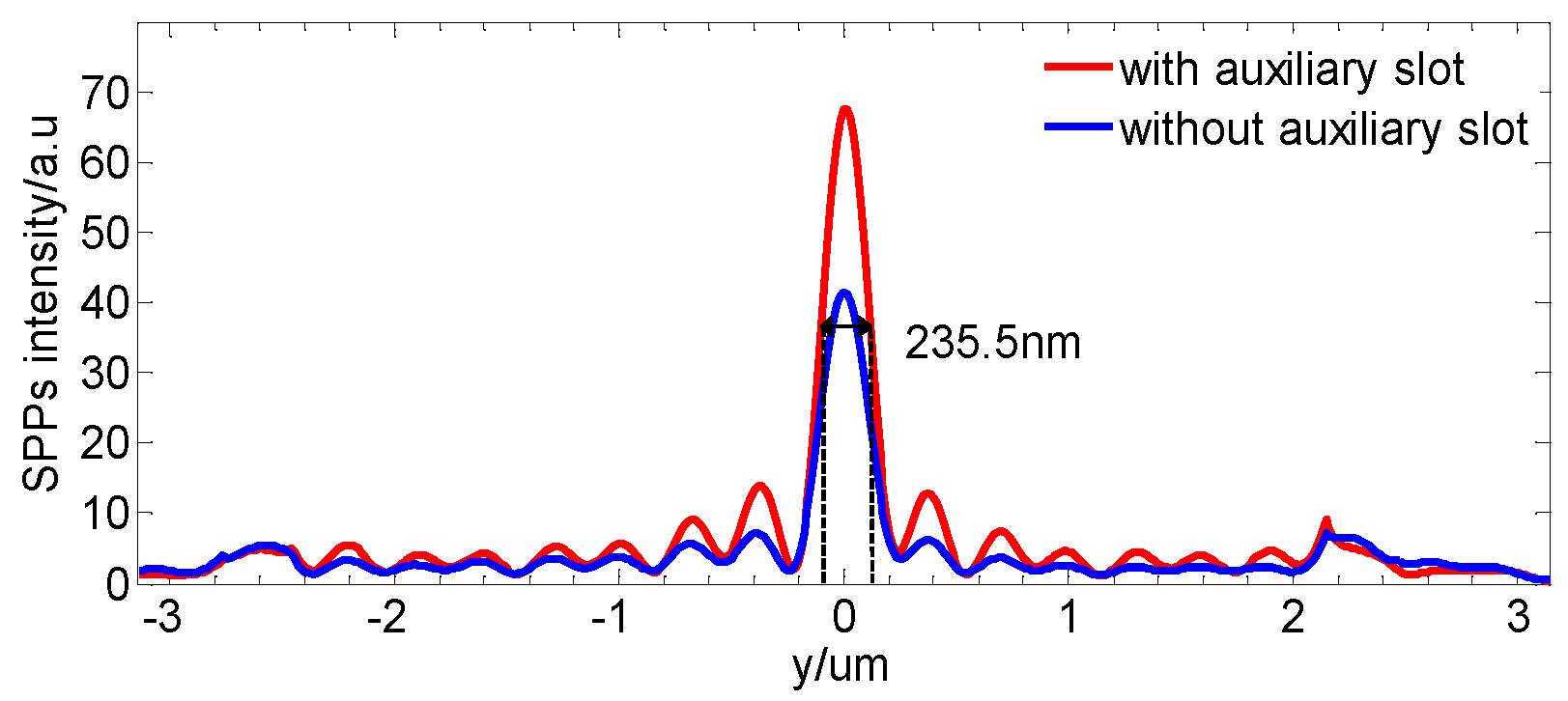
To obtain the electric field distribution of the hot spot, the one-dimensional intensity profile along the y-axis of the focused spot in the center of the spiral slot illuminated by a left polarized light is shown in Figure 4. The red and the blue lines represent the intensity profiles of the hot spots focused by the structure with and without the auxiliary spiral slot. It is eventually visible that almost no plasmonic waves are propagating outside the spiral slot of our plasmonic lens. All the power contributes to the nanofocusing of the plasmonic waves. The electric field intensity of the plasmonic hot spot normalized to the intensity of the incident light can be increased to 67.6, which is about 1.63 times the value for the plasmonic lens without the auxiliary spiral slot. We also found that the full width at half maximum of the hot spot of our plasmonic lens is approximately 235.5 nm, which is 0.38 times the value of the SPPs’ wavelength λSPP at the silver–air interface.
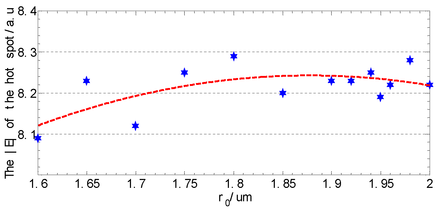
Next, we investigated the influence rule of the inner radius of the spiral slot r0 on the focusing properties of our lens by the FDTD simulation method. The incident light is a left-circularly polarized light at the wavelength of λ = 633 nm and the spiralling of the slot parameter m = 1. We found that the focused hot spots of our lens were obtained when r0 is set to different values. The relation between the electric field |E| of the hot spot and the parameter r0 is shown in Figure 5.
The blue dots in the Figure 5 are simulation results of the electric field |E| of the hot spots with different values of r0. The red dashed line is the trend line fitted to the blue dots. The results show that the hot spot electric field |E| initially increases and then decreases. This could be attributed to the increase in the spiral slot length as the r0 increases. However, the SPPs’ ohmic losses of the metal layer increase with the increase in r0, which could be the reason for the decrement of the hot spot electric field |E| when r0 increases to exceed a certain extent.

3.3. Analysis of the Plasmonic Lens Based on a Spiral Slot Illuminated by a Linearly Polarized Beam

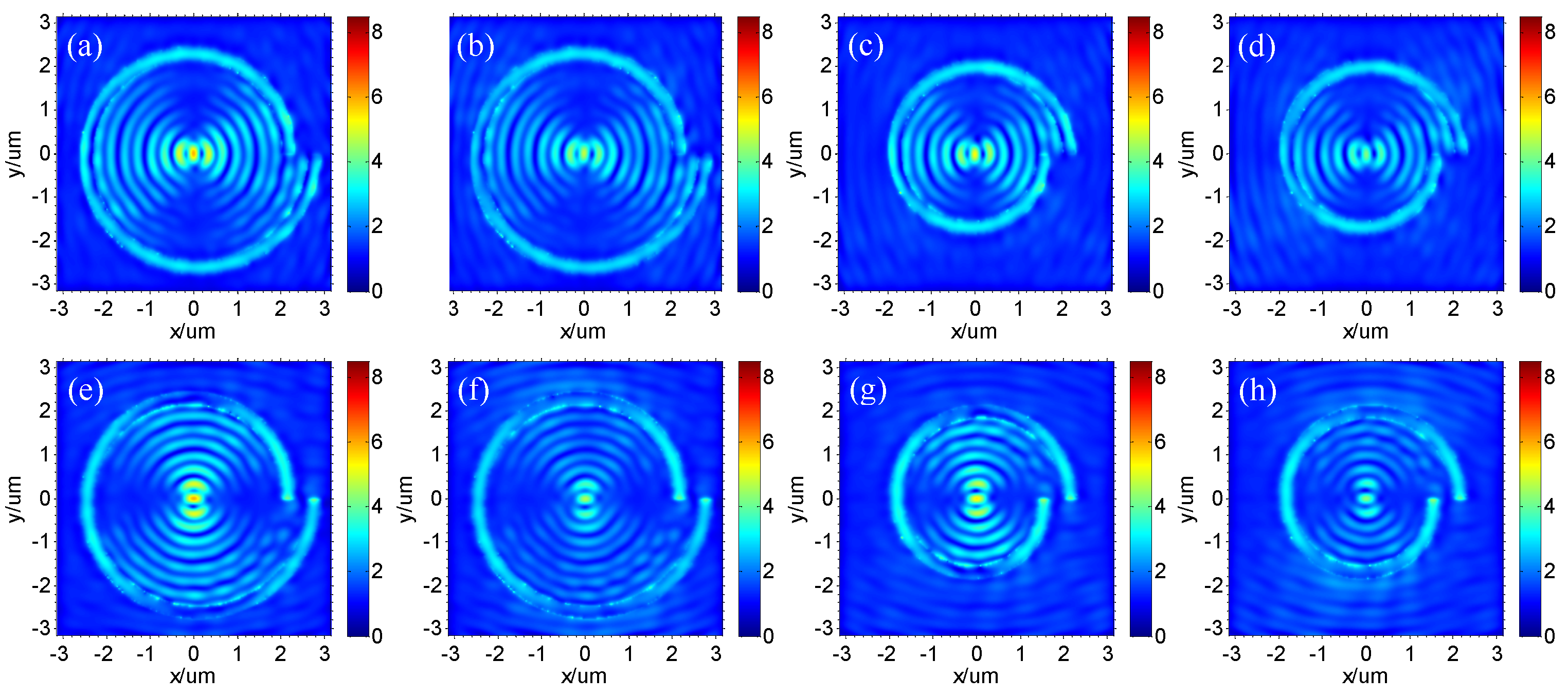
Figure 6 shows the focusing properties of the plasmonic lens with different structures, illuminated by a linearly polarized light (including x-axis and y-axis direction polarized light, λ = 633 nm) with normal incidence from the top of the silver film. Figure 6a is the |E| distribution when the spiraling of the slot parameter m = 1, with an auxiliary spiral slot and illuminated by an x-axis direction polarized light. Figure 6b is the same as Figure 6a but for the structure without an auxiliary spiral slot. Figure 6c is the same as Figure 6a but for m = −1. Figure 6d is the same as Figure 6c but for the structure without an auxiliary spiral slot. Figure 6e–h are the same as Figure 6a–d, respectively, but with a y-axis-direction polarized beam for the incident light.
We can see that a high-intensity hot spot is formed in the center of the plasmonic lens, regardless of the spiraling of the slot parameter m = 1 or 1, or whether illuminated by an x- or y-polarized light, shown as Figure 6a,c,e,g. x- or y-axis-direction polarized light can generate plasmonic waves with antiphase at the antipodal point of the spiral slot. The optical path difference of the plasmonic waves from the antipodal point of the spiral slot to the center of the lens is ± λ S P P / 2 when m = ±1. Therefore, the plasmonic waves excited by x- or y-polarized light at the antipodal point of the spiral slot interfere constructively when propagating to the center of the lens due to the total phase difference of 0 or 2 π and then focused on a hot spot in the center.
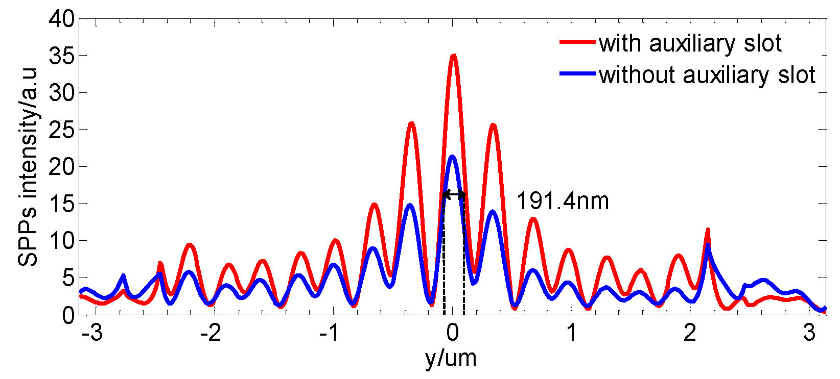
Similar to Figure 3, we also found that plasmonic waves propagate outside the single spiral slit without the auxiliary spiral slot, as shown in Figure 6b,d,f,h. Hence, the outward propagating SPPs can be weakened by adding an auxiliary spiral slot, and the intensity of the hot spot is further enhanced. Figure 7 shows the intensity profile of the hot spot along the y-axis in the center of the surface plasmonic lens with and without the auxiliary spiral slot illuminated by a y-axis-direction polarized light. The electric field intensity of the plasmonic hot spot normalized to the intensity of the incident light can reach up to 61.6, which is about 1.64 times the value for the plasmonic lens without the auxiliary spiral slot. The full width at half maximum of the hot spot is approximately 191.4 nm, which is 0.31 times the value of the SPPs wavelength λSPP at the silver–air interface.

4. Conclusions

In this paper, a high excitation efficiency plasmonic lens with a simple structure that is illuminated by a circularly or linearly polarized light is presented. It consists of a primary and an auxiliary Archimedes-spiral slot. By adding the auxiliary spiral slot, the excited plasmonic waves propagate only in the inward direction of the lens. The electric field intensity of the plasmonic hot spot normalized to the intensity of the incident light can be increased to 67.6, which is about 1.63 times the value for the plasmonic lens without the auxiliary spiral slot. The full width at half maximum of the hot spot is approximately 0.38 times the value of the SPPs wavelength λSPP at the silver–air interface. These kinds of plasmonic lenses can minimize the inter-coupling between optical components, which is of great importance for future optical integration chips.

Author Contributions

Conceptualization and methodology, Y.Z., Q.W., J.W., D.Z. and S.Z.; software, Y.Z.; resources, Q.W., J.W. and D.Z.; writing—original draft preparation, Y.Z.; writing—review and editing, Q.W., J.W., D.Z. and Y.Z.; All authors have read and agreed to the published version of the manuscript.

Funding

This research was supported by the National Natural Science Foundation of China, grant numbers 61775141 and 62075133.

Data Availability Statement

The data in this study are available from the corresponding authors upon request.

Conflicts of Interest

The authors declare no conflict of interest.

References

  1. Rothenhäusler, B.; Knoll, W. Surface plasmon microscopy. Nature 1988, 332, 615–617. [Google Scholar] [CrossRef]
  2. Mao, Y.; Chang, S.; Sherif, S.; Flueraru, C. Graded-index fiber lens proposed for ultrasmall probes used in biomedical imaging. Appl. Opt. 2007, 46, 5887–5894. [Google Scholar] [CrossRef] [PubMed]
  3. Fang, N.; Lee, H.; Sun, C.; Zhang, X. Sub-diffraction-limited optical imaging with a silver superlens. Science 2005, 308, 534–537. [Google Scholar] [CrossRef] [PubMed] [Green Version]
  4. Liu, Z.; Lee, H.; Xiong, Y.; Sun, C.; Zhang, X. Far-field optical hyperlens magnifying sub-diffraction-limited objects. Science 2007, 315, 1686. [Google Scholar] [CrossRef] [Green Version]
  5. Srituravanich, W.; Pan, L.; Wang, Y.; Sun, C.; Bogy, D.; Zhang, X. Flying plasmonic lens in the near field for high-speed nanolithography. Nat. Nanotechnol. 2008, 3, 733–737. [Google Scholar] [CrossRef] [PubMed]
  6. Liu, Z.W.; Wei, Q.H.; Zhang, X. Surface plasmon interference nanolithography. Nano Lett. 2005, 5, 957–961. [Google Scholar] [CrossRef]
  7. Pang, Y.; Gordon, R. Optical trapping of 12 nm dielectric spheres using double-nanoholes in a gold film. Nano Lett. 2011, 11, 3763–3767. [Google Scholar] [CrossRef]
  8. Tsai, W.Y.; Huang, J.S.; Huang, C.B. Selective trapping or rotation of isotropic dielectric microparticles by optical near field in a plasmonic archimedes spiral. Nano Lett. 2014, 14, 547–552. [Google Scholar] [CrossRef]
  9. Roxworthy, B.J.; Ko, K.D.; Kumar, A.; Fung, K.H.; Chow, E.K.C.; Liu, G.L.; Fang, N.X.; Toussaint, K.C. Application of plasmonic bowtie nanoantenna arrays for optical trapping, stacking, and sorting. Nano Lett. 2012, 12, 796–801. [Google Scholar] [CrossRef]
  10. Wang, K.; Schonbrun, E.; Steinvurzel, P.; Crozier, K.B. Scannable plasmonic trapping using a gold stripe. Nano Lett. 2010, 10, 3506–3511. [Google Scholar] [CrossRef]
  11. Haes, A.J.; Zou, S.; Schatz, G.C.; Duyne, R.P.V. Nanoscale optical biosensor: Short range distance dependence of the localized surface plasmon resonance of noble metal nanoparticles. J. Phys. Chem. B 2004, 108, 6961–6968. [Google Scholar] [CrossRef]
  12. Dahlin, A.; Zäch, M.; Rindzevicius, T.; Käll, M.; Sutherland, D.S.; Höök, F. Localized surface plasmon resonance sensing of lipid-membrane-mediated biorecognition events. J. Am. Chem. Soc. 2005, 127, 5043–5048. [Google Scholar] [CrossRef] [PubMed]
  13. Zhao, C.; Zhang, J. Binary plasmonics: Launching surface plasmon polaritons to a desired pattern. Opt. Lett. 2009, 34, 2417–2419. [Google Scholar] [CrossRef] [PubMed]
  14. Li, H.; Yan, L.S.; Guo, Z.; Pan, W.; Wen, K.H.; Luo, X. Enhanced focusing properties using surface plasmon multilayer gratings. IEEE Photonics J. 2012, 4, 57–64. [Google Scholar] [CrossRef]
  15. Lerman, G.M.; Yanai, A.; Levy, U. Demonstration of nanofocusing by the use of plasmonic lens illuminated with radially polarized light. Nano Lett. 2009, 9, 2139–2143. [Google Scholar] [CrossRef]
  16. Lv, X.M.; Qiu, W.B.; Wang, J.X.; Ma, Y.H.; Zhao, J.; Li, M.K.; Yu, H.Y.; Pan, J.Q. A chirped subwavelength grating with both reflection and transmission focusing. IEEE Photonics J. 2013, 5, 2200907. [Google Scholar]
  17. Zhang, Q.; Shan, X.Y.; Zhou, L.; Zhan, T.R.; Wang, C.X.; Li, M.; Jia, J.F.; Zi, J.; Wang, Q.Q.; Xue, Q.K. Scattering focusing and localized surface plasmons in a single ag nanoring. Appl. Phys. Lett. 2010, 97, 261107. [Google Scholar] [CrossRef]
  18. Fu, Y.; Liu, H.; Zhou, X.; Xu, Z.; Fang, F. Experimental investigation of superfocusing of plasmonic lens with chirped circular nanoslits. Opt. Express 2010, 18, 3438–3443. [Google Scholar] [CrossRef]
  19. Zhang, M.; Du, J.; Shi, H.; Yin, S.; Xia, L.; Jia, B.; Gu, M.; Du, C. Three-dimensional nanoscale far-field focusing of radially polarized light by scattering the spps with an annular groove. Opt. Express 2010, 18, 14664–14670. [Google Scholar] [CrossRef]
  20. Wang, E.W.; Li, L.L.; Yu, W.X.; Wang, T.S.; Gao, J.S.; Fu, Y.Q.; Liu, Y.L. The focusing property of immersed plasmonic nanolenses under radially polarized illumination. IEEE Photonics J. 2013, 5, 4500207. [Google Scholar] [CrossRef]
  21. Chen, J. Numerical study of a nonplanar two-stage surface plasmonic lens illuminated by a radially polarized beam. Plasmonics 2013, 8, 931–936. [Google Scholar] [CrossRef]
  22. Jia, S.; Wu, Y.; Wang, X.; Wang, N. A subwavelength focusing structure composite of nanoscale metallic slits array with patterned dielectric substrate. IEEE Photonics J. 2014, 6, 4800108. [Google Scholar] [CrossRef]
  23. Gjonaj, B.; David, A.; Blau, Y.; Spektor, G.; Orenstein, M.; Dolev, S.; Bartal, G. Sub-100 nm focusing of short wavelength plasmons in homogeneous 2d space. Nano Lett. 2014, 14, 5598–5602. [Google Scholar] [CrossRef]
  24. Takeda, M.; Kimura, N.; Inoue, T.; Aizawa, K. Plasmonic lens with multi-circular-slit apertures for improvement of light utilization efficiency. Jpn. J. Appl. Phys. 2015, 54, 09MG02. [Google Scholar] [CrossRef]
  25. Zhao, C.; Zhang, J.; Liu, Y. Light manipulation with encoded plasmonic nanostructures. EPJ Appl. Metamater. 2014, 1, 6. [Google Scholar] [CrossRef] [Green Version]
  26. Zhao, C.; Zhang, J. Flexible wavefront manipulation of surface plasmon polaritons without mechanical motion components. Appl. Phys. Lett. 2011, 98, 211108. [Google Scholar] [CrossRef]
  27. Chen, W.; Abeysinghe, D.C.; Nelson, R.L.; Zhan, Q. Plasmonic lens made of multiple concentric metallic rings under radially polarized illumination. Nano Lett. 2009, 9, 4320–4325. [Google Scholar] [CrossRef] [Green Version]
  28. Darak, M.S.; Mote, R.G.; Shukla, S. Asymmetry-Based Plasmonic Phase Manipulation for a Compact Far-Field Optical Lens. Adv. Photonics Res. 2020, 1, 2000018. [Google Scholar] [CrossRef]
  29. Mote, R.G.; Minin, O.V.; Minin, I.V. Focusing behavior of 2-dimensional plasmonic conical zone plate. Opt. Quantum Electron. 2017, 49, 271. [Google Scholar] [CrossRef]
  30. Wang, S.; He, J.; Qu, S.; Zhang, Y. Metasurface Lens for both Surface Plasmon Polaritons and Transmitted Wave. Plasmonics 2016, 12, 621–626. [Google Scholar] [CrossRef]
  31. Shi, W.B.; Chen, T.Y.; Jing, H.; Peng, R.W.; Wang, M. Dielectric lens guides in-plane propagation of surface plasmon polaritons. Opt. Express 2017, 25, 5772. [Google Scholar] [CrossRef] [PubMed]
  32. Li, G.; Sun, Y.; Wang, S. Spin-Independent Plasmonic Lens. Nanoscale Res. Lett. 2019, 14, 156. [Google Scholar] [CrossRef] [PubMed] [Green Version]
  33. Liu, Z.; Steele, J.M.; Srituravanich, W.; Pikus, Y.; Sun, C.; Zhang, X. Focusing surface plasmons with a plasmonic lens. Nano Lett. 2005, 5, 1726–1729. [Google Scholar] [CrossRef] [PubMed]
  34. Zhu, M.; Zhang, D.; Zhu, L.; Chen, J. A near infrared broadband surface plasmonic lens constructed with multiple couplers with unidirectional propagation property. Plasmonics 2015, 10, 1315–1323. [Google Scholar] [CrossRef]
  35. Steele, J.M.; Liu, Z.; Wang, Y.; Zhang, X. Resonant and non-resonant generation and focusing of surface plasmons with circular gratings. Opt. Express 2006, 14, 5664–5670. [Google Scholar] [CrossRef]
  36. Song, W.; Fang, Z.; Huang, S.; Lin, F.; Zhu, X. Near-field nanofocusing through a combination of plasmonic bragg reflector and converging lens. Opt. Express 2010, 18, 14762–14767. [Google Scholar] [CrossRef]
  37. Zhong, Y.; Wen, J.; Chen, J.; Zhu, L.; Gao, X.; Tao, C.; Zhang, D. A highly efficient plasmonic lens based on a single annular ring with cross section of an asymmetric slot. IEEE Photonics J. 2016, 8, 4801309. [Google Scholar] [CrossRef]
  38. Takeda, M.; Okuda, S.; Inoue, T.; Aizawa, K. Focusing characteristics of a spiral plasmonic lens. Jpn. J. Appl. Phys. 2013, 52, 09LG03. [Google Scholar] [CrossRef]
  39. Gou, Q.; Zhang, C.; Hu, X. A spiral plasmonic lens with directional excitation of surface plasmons. Sci. Rep. 2016, 6, 32345. [Google Scholar]
  40. Yao, W.; Liu, S.; Liao, H.; Li, Z.; Sun, C.; Chen, J.; Gong, Q. Efficient directional excitation of surface plasmons by a single-element nanoantenna. Nano Lett. 2015, 15, 3115–3121. [Google Scholar] [CrossRef]
  41. Johnson, P.B.; Christy, R.W. Optical constants of the noble metals. Phys. Rev. B 1972, 6, 4370. [Google Scholar] [CrossRef]
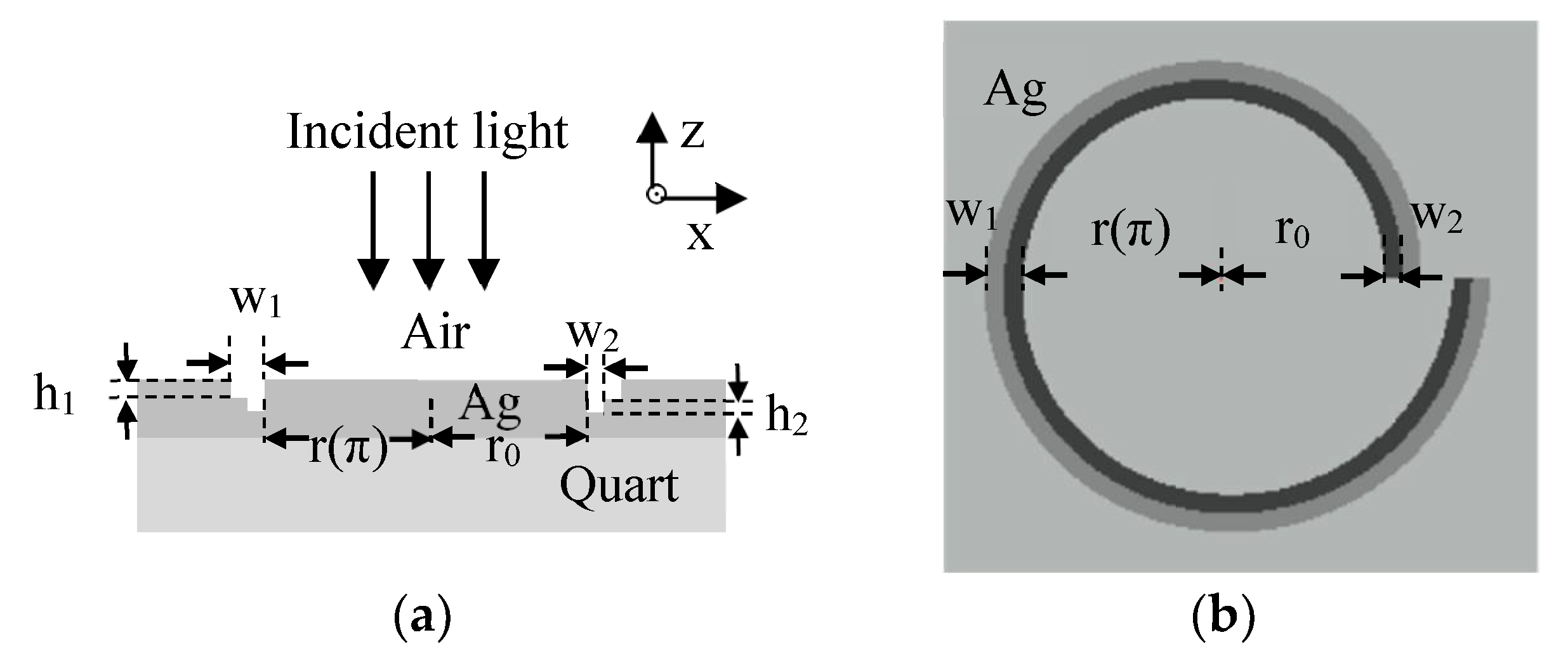
Figure 1. Schematic view for (a) the cross-section and (b) the top view of the surface plasmonic lens.
Crystals 12 00316 g001
Figure 2. Schematic view of (a) 2D symmetric MIM slot and (b) 2D asymmetric slot with a primary MIM slot and an auxiliary cavity.
Crystals 12 00316 g002
Figure 3. The electric field distribution | E | on the top surface of the plasmonic lens with different structures, illuminated by a circularly polarized beam   (   λ = 633   nm ) with normal incidence from the top of the silver film, w 1 = 310   nm ,   w 2 = 155   nm , h 1 = 110   nm , h 2 = 45   nm ,   r 0 = 2000   nm . (a) | E | distribution when the spiraling of the slot parameter m = 1, with an auxiliary spiral slot and illuminated by a left-circularly polarized light. (b) is the same as (a) but for the structure without an auxiliary spiral slot. (c) is the same as (a) but for m = 1. (d) is the same as (c) but for the structure without an auxiliary spiral slot. (eh) are the same as (ad), respectively, but for right-circularly polarized incident light.
Crystals 12 00316 g003
Figure 4. The intensity profile of the hot spot along y-axis in the center of the surface plasmonic lens with and without the auxiliary spiral slot illuminated by a left polarized light, w1 = 310 nm, w2 = 155 nm, h1 = 110 nm, h2 = 45 nm, r0 = 2000 nm, m = 1, λ = 633 nm.
Crystals 12 00316 g004
Figure 5. The relation between the electric field |E| of the hot spot and the parameter r0 when our lens was illuminated by a left-circularly polarized light, w1 = 310 nm, w2 = 155 nm, h1 = 110 nm, h2 = 45 nm, m = 1, λ = 633 nm, r0 are set to 1.6 um, 1.65 um, 1.7 um, 1.75 um, 1.8 um, 1.85 um, 1.9 um, 1.92 um, 1.94 um, 1.95 um, 1.96 um, 1.98 um, 2.0 um, respectively.
Crystals 12 00316 g005
Figure 6. The electric field distribution | E | on the top surface of the plasmonic lens with different structures, illuminated by a linearly polarized beam (   λ = 633   nm ) with normal incidence from the top of the silver film, w 1 = 310   nm , w 2 = 155   nm , h 1 = 110   nm , h 2 = 45   nm ,   r 0 = 2000   nm . (a) | E | distribution when the spiraling of the slot parameter m = 1, with an auxiliary spiral slot and illuminated by an x-axis direction polarized light. (b) is the same as (a) but for the structure without an auxiliary spiral slot. (c) is the same as (a) but for m = −1. (d) is the same as (c) but for the structure without an auxiliary spiral slot. (eh) are the same as (ad), respectively, but with a y-axis-direction polarized beam for the incident light.
Crystals 12 00316 g006
Figure 7. The intensity profile of the hot spot along the y-axis in the center of the surface plasmonic lens with and without the auxiliary spiral slot illuminated by a y-axis direction polarized light, w1 = 310 nm, w2 = 155 nm, h1 = 110 nm, h2 = 45 nm, r0 = 2000 nm, m = 1, λ = 633 nm.
Crystals 12 00316 g007
Publisher’s Note: MDPI stays neutral with regard to jurisdictional claims in published maps and institutional affiliations.