Article

Study on the Molten Pool Fluid Behavior of PAW-Cable-Type Seven-Wire GMAW Hybrid Welding

1
Public Utilities School, Jiangsu Urban and Rural Construction College, Changzhou 213003, China
2
School of Materials Science and Engineering, Jiangsu University of Science and Technology, Zhenjiang 212003, China
*
Author to whom correspondence should be addressed.
Crystals 2022, 12(3), 306; https://doi.org/10.3390/cryst12030306
Submission received: 22 January 2022 / Revised: 11 February 2022 / Accepted: 16 February 2022 / Published: 22 February 2022

Abstract

:
Plasma arc welding (PAW)-cable-type seven-wire GMAW (gas metal arc welding) hybrid welding is known as a high-efficiency welding combining plasma arc, GMAW arc and cable-type welding wire. In this study, numerical simulation via Fluent of the molten pool temperature field and flow field and experimental verification were conducted on Q235 thin plate hybrid welding with cable-type wire to explore molten pool fluid behavior. The simulation results show that keyholes form in the molten pool due to the strong penetration ability of a plasma arc and then the evolved pores by the surface tension float out of the molten pool. When the GMAW welding current increases, both the length and width of the weld pool enlarge, the weld reinforcement increases and the flow rate of molten metal in the weld pool also speeds up. While the PAW current increases, the weld pool length also increases and the molten metal in the weld pool significantly flows faster, but the weld reinforcement decreases. When the welding speed increases, the weld pool length and fusion depth decrease, but the reinforcement will first increase and then decrease. The experimental results are in strong agreement with the simulation results. It shows that the numerical analysis model established in this paper is accurate, laying a certain theoretical foundation for the popularization of PAW-cable-type seven-wire GMAW hybrid welding.

1. Introduction

Arc welding has a large place in today’s industrial production. Hybrid welding by superimposing multiple arc welding heat sources can greatly improve welding efficiency [1,2]. In the 1970s, W. G. Essers and A. C. Liefken from Philips Research Labs (the Netherlands) proposed a new process combining plasma arc welding (PAW) and metal inert-gas welding (MIG) [3], which can achieve greater depth of fusion by the compressed plasma arc and larger width of fusion by the spreading MIG arc so as to improve welding quality and welding efficiency. With the development of welding technology, two types of plasma-MIG hybrid welding have been evolved—a coaxial type by Philips and a paraxial by the Paton Welding Institute [4,5,6]. The research findings about gas metal arc welding (GMAW) with cable-type welding wire show that the melting speed of cable-type welding wire is 1.45 times that of ordinary welding wire, the deposition rate is 1.35 times and the electric energy efficiency is about 1.2 times [7,8]. In this paper, an innovative and efficient PAW-cable-type seven-wire GMAW hybrid welding was used by paraxially combining the plasma-GMAW hybrid welding and the cable-type welding wire GMAW welding. Compared with traditional welding, it can achieve high welding quality, high welding efficiency and less welding consumables [9]. However, during PAW-cable-type seven-wire GMAW hybrid welding, the dynamic behavior of molten pool fluid is complex, and the multi arc rotation coupling of cable-type GMAW welding arc and the mutual interference of inter-electrode arc have a great impact on the heat and mass transfer in the welding process. Therefore, it is necessary to research the molten fluid behavior of this innovative hybrid in order to understand the heat and mass transfer process. The numerical simulation becomes a useful tool and is reliable for now, as it has many advantages compared to the experimental method. Then, the molten fluid behavior of this hybrid welding is studied by using numerical analysis.
Many studies have numerically simulated the heat source mechanism of PAW-MIG hybrid welding. Zhang et al. [10,11] simulated the welding temperature field with double arc and single arc by ANSYS. During coaxial hybrid welding, with the increase of the distance between two arcs, the maximum fusion depth and the maximum fusion width decrease. But when the total heat input of welding remains unchanged, the reduction of fusion depth and fusion width is not large. Hertel [12] integrated the simulation calculation of arc, droplet and molten pool, and found that the MIG welding stage is an important factor affecting the stability of the whole welding process. Wei [13] and Huo [14] selected two groups of heat source combinations with a power ratio of 0.33:0.67 to simulate the temperature field of 5083 aluminum alloy plasma-MIG hybrid welding through the Gaussian double ellipsoid heat source combination model established by SYSWELD. The simulated result is consistent with the actual change of plasma current it is positively correlated with, while the welding speed is inversely correlated with the weld fusion depth and width. Piao et al. [15,16] established a unified three-dimensional mathematical model of arc and weld pool for paraxial plasma-MIG hybrid welding and obtained the temperature field and flow field distribution data of the weld pool. The temperature distribution of a plasma arc is an inverted cone shape, while that of an MIG/MAG arc is a typical bell shape. The front part of the weld pool is deep and wide, and the rear part gradually becomes shallow and narrow, conforming to the shape of a double ellipsoid.
Cable-type wire has been applied to CO2 gas shielded welding, submerged arc welding, double wire welding and other welding methods [17,18], which has brought many numerical simulation research results for relevant molten pool flow fields. Fang, Zhou, Xu et al. [4,6] added the numerical simulation analysis method to the traditional test method. It was found that the temperature field distribution and thermal cycle curve of a submerged arc welding and cable-type wire CO2 gas shielded welding are similar, that the maximum temperature of thermal cycle at each characteristic point of CO2 gas shielded welding with cable welding wire is low, and that the range of high temperature zone on the lower surface of molten pool and the fusion depth is large. Moreover, the shorter the grain heating time in the heat affected zone, the better the mechanical properties of the weld. Leng [19] established the numerical analysis model of double cable GMAW welding and compared the temperature field distribution of ordinary single wire gas shielded welding, cable wire gas shielded welding and double cable GMAW welding. The results show that the temperature field distribution range of double cable GMAW welding pool is wider, which can effectively reduce the pool temperature and is suitable for narrow gap welding.
In this paper, the theoretical research on the fluid behavior in the molten pool was carried out to reveal the heat and mass transfer mechanism and theoretical basis of PAW-cable-type seven-wire GMAW hybrid welding. The mathematical model suitable for plasma-GMAW hybrid welding was established, and the effects of GMAW welding current, PAW current and welding speed on the molten pool fluid behavior during PAW-cable-type seven-wire GMAW hybrid welding were studied. Moreover, the macro morphology of weld was compared with the simulation results to verify the simulation model.

2. Materials and Methods

The experiment was carried out on a 300 mm × 100 mm × 6 mm Q235B carbon steel plate with a cable wire ER50-6 1.6mm in diameter. The chemical compositions of the welding wire and Q235B are shown in Table 1. The melting point temperature of Q235B is 1723K.
A novel high-efficiency Super-GMAW welding system was applied to conduct paraxial plasma-GMAW hybrid welding (as shown in Figure 1) [9]. For GMAW welding, it can control GMAW welding current, arc voltage and wire feeding speed. For plasma welding, it can control plasma arc current, plasma gas flow and shielding gas flow. During the whole welding process, it can also change welding parameters such as welding speed, included angle of welding torch, distance between welding wire and tungsten electrode, etc. There are many changes in the combination of various parameters. Different welding parameters can achieve different welding effects.
In this study, welding process parameters were set as invariant except the welding current and welding speed. The plasma arc was in front and perpendicular to the surface of the workpiece to be welded, and the GMAW arc was in the rear at a 15° angle with the plasma arc. The distance between the welding wire and the workpiece was 10 mm, the distance between the wire and tungsten electrode was 15 mm, the stickout was 15 mm, the angle between welding guns was 15°, the shielding gas of the GMAW was mixed by 80% Ar and 20% CO2, the gas flow was 15 L/min, the diameter of the plasma nozzle and tungsten electrode were both 3.2 mm and the plasma gas of the PAW was pure argon with a plasma flow rate of 2.0 L/min. During welding, the plasma arc started first and, ignited the GMAW arc until the plasma arc was stable. The mode of the MAG metal transfer is spray arc. This paper focuses only on the influences of GMAW welding current, PAW current and welding speed on the weld formation of Q235 steel plate. Table 2 lists the welding parameters.

3. Numerical Models of the Hybrid Welding

Given the following assumptions for the simulation:
(1)
The liquid metal in the molten pool is incompressible laminar Newtonian fluid;
(2)
The welding wire has the same thermo-physical properties and chemical composition as the base metal;
(3)
Only electromagnetic force, surface tension, arc pressure, buoyancy and gravity need to be considered in the molten pool;
(4)
The current density and the heat flux density of the welding arc are in Gaussian distribution.
Governing equations describing heat transfer and flow in molten pool include energy, momentum and mass conservation equations, as per [20].

3.1. Heat Source Model of the Hybrid Welding

3.1.1. GMAW Arc Heat Input Model

In the process of hybrid welding, under the arc pressure and plasma force, some deformation will occur on the surface of the molten pool (the area around the keyhole). Due to the fast welding speed, the arc heat input distribution should be described by a double ellipsoid heat source model [21]. During calculation, the heat source center is located on the surface of the weldment, and its heat flux density distribution function is as follows:
q f ( x , y , z ) = 6 3 ( f f η A I U ) a f b h c h π π exp ( 3 ( x v 0 t ) 2 a f 2 3 y 2 b h 2 3 z 2 c h 2 ) , x 0
q f ( x , y , z ) = 6 3 ( f r η A I U ) a r b h c h π π exp ( 3 ( x v 0 t ) 2 a r 2 3 y 2 b h 2 3 z 2 c h 2 ) , x < 0
f f + f r = 2
where I is the welding current, U is the arc voltage, ηA is the arc thermal efficiency, v0 is the welding speed, t is time, af, ar, bh and ch are the heat source distribution parameters and ff and fr are the heat distribution coefficient of the front and rear part of the heat source.

3.1.2. Plasma Arc Heat Input Model

A plasma-induced keyhole will appear during welding when the plasma energy density reaches a certain value. Thus, when establishing the keyhole model, the thermal-dynamic balance of the keyhole should be taken into account. By comprehensively considering the steam reaction force, surface tension, arc pressure, gravity and other forces, a suitable conical heat source model is preliminarily established. To improve the calculation efficiency, the research focuses on the fluid flow and keyhole shape in the hybrid welding pool. The hyperbolic rotating body heat source model with adjustable heat flow peak value based on the keyhole size is used to describe the plasma heat flow distribution mode. The heat flux distribution parameters are as follows:
q ( r , z ) = Q 0 exp ( ln ( χ ) z i z e ( z z e ) ) exp ( 3 r 2 [ r 0 ( z ) ] 2 )
Q 0 = 3 Q ln ( χ ) π ( 1 e 3 ) ( z i z e ) A
A = { r e 2 r i 2 χ 2 r i r e ln ( χ ) [ r e r i χ r i r e ln ( χ ) ( 1 χ ) ] }
r 0 ( z ) = a z + b
{ a = r i r e z i z e b = r e z i r i z e z i z e
where r and z are the coordinate values, r = ( x v 0 t ) 2 + y 2 , r0(z) is the action radius of the heat source, re and ri are the radii of the upper and lower surfaces of the heat source, respectively, ze and zi are the coordinates of the upper and lower surfaces of the heat source, respectively, Q is the effective heat input of the plasma arc, χ is the ratio coefficient of the peak heat flow on the upper and lower surfaces of the heat source and a and b are the calculation parameters.
The conical heat source radius linearly reduces along the thickness direction. Moreover, the heat flux peak value along the heat source central axis changes exponentially along the direction of weld thickness, exponentially increasing when the scale coefficient is greater than 1, while exponentially decreasing when less than 1. In any section of the heat source, the heat flow is in Gaussian distribution, that is, the heat source is superimposed of a series of Gaussian plane heat sources with different heat source radii and heat flow peaks [22].

3.2. Forces Analysis of Molten Pool

The keyhole has a strong stirring effect on the fluid in the molten pool during hybrid welding. The influence of keyhole dynamic behavior on the hybrid welding fluid flow mode must be considered in the process of numerical simulation.
Regard the keyhole as the surface deformation of the molten pool under the combined action of the plasma-induced steam reaction force, arc pressure and surface tension, and ignore the effects of the plasma thermal field and force field inside the keyhole. The following stress boundary condition exists on the free surface of the molten pool:
P = P A + P R P S
where P is the pressure acting on the free surface of the molten pool, PA is the arc pressure, PR is the steam reaction force and PS is the surface tension.

3.2.1. Arc Pressure

The arc pressure adopts the double ellipse distribution mode:
P A ( x , y ) = C 3 μ 0 I 2 2 π 2 ( a j 1 + a j 2 ) b j exp ( 3 ( x v 0 t ) 2 a j 1 2 3 y 2 b j 2 ) , x 0
P A ( x , y ) = C 3 μ 0 I 2 2 π 2 ( a j 1 + a j 2 ) b j exp ( 3 ( x v 0 t ) 2 a j 2 2 3 y 2 b j 2 ) , x < 0
where μ0 is the magnetic permeability, C is the calculation coefficient and aj1, aj2 and bj are the arc pressure distribution coefficients.

3.2.2. Steam Reaction Force

The main force driving the formation of the keyhole is the steam reaction force, which is expressed as
P R = A 0 B 0 T w exp ( U 0 T w )
U = m a L b N a k a
where A0 and U0 are the calculation coefficients, B0 is the evaporation constant, Tw is the surface temperature of the molten pool, ma is the atomic mass, Lb is the latent heat of evaporation, Na is the Avogadro constant and ka is the Boltzmann constant.

3.2.3. Surface Tension

On the surface of the molten pool, the surface tension of the fluid is usually in equilibrium with the viscous shear force of the fluid. The expression is as follows [15]:
μ u z = γ T T x
μ v z = γ T T y
where γ is the surface tension, γ T is the temperature coefficient of the surface tension and μ is the fluid viscosity coefficient.

3.2.4. Electromagnetic Force

The components of electromagnetic force in the x, y and z coordinate axes are:
F x = μ 0 I 2 4 π 2 σ j 2 r exp ( r 2 2 σ j 2 ) [ 1 exp ( r 2 2 σ j 2 ) ] ( 1 z L ) 2 x r
F y = μ 0 I 2 4 π 2 σ j 2 r exp ( r 2 2 σ j 2 ) [ 1 exp ( r 2 2 σ j 2 ) ] ( 1 z L ) 2 y r
F z = μ 0 I 2 4 π 2 L r 2 [ 1 exp ( r 2 2 σ j 2 ) ] 2 ( 1 z L )
where μ0 is the permeability of vacuum, L is the thickness of the workpiece, I is the welding current and r is the distance to the arc center.

3.2.5. Buoyancy

The buoyancy term is related to the direction of gravity and only appears in the source term of the z-direction momentum equation:
S B = ρ g β ( T T m )
where SB is the buoyancy, β is the expansion coefficient, T is the actual temperature and Tm is the melting temperature of the metal.

3.2.6. Plasma Flow Force

Considering the normal distribution of arc, the characteristic expression [23] is
P ( r ) = P max C X P ( α r 2 )
where Pmax is the peak pressure, α is the concentration coefficient of the distribution curve, which is constant, and r is the radial coordinate value.

3.3. Pool Surface Tracking

The multiphase VOF model was used to track the gas-liquid free interface. If the volume fraction of the fluid satisfies F(x,y,z,t) = 1, it means that the cell corresponding to it is filled with liquid. If 0 < F(x,y,z,t) < 1, the liquid surface is in the cell. When F(x,y,z,t) = 0, it means that there is no liquid in the corresponding cell. Therefore, F can be used to calculate the free surface element and its normal direction. The governing equation of the fluid volume function F [24] is:
F t + u F z + v F y + w F z = 0
where u, v, w are, respectively, the flow rate of x, y, z directions.

3.4. Meshing

The meshing of the PAW-GMAW hybrid welding calculation model is shown in Figure 2 and the boundary conditions are set. The air layer 3 mm in thickness is above the groove of the workpiece 6 mm in thickness.
The x, y and z axes represent, respectively, the length, width and thickness directions of the workpiece. The welding direction is the positive direction of the x axis and the gravity direction is the reverse direction of the z axis. Because the heat transfer in the weld center and near the weld is intense, these areas of the model have been densified twice.

3.5. Solution

Adopt the fluid dynamics software Fluent to simulate and calculate the molten pool fluid behavior of the plasma-GMAW hybrid-heat-source welding. Fluent can achieve the fastest convergence speed and the highest solution accuracy by using multi solution method and multi grid accelerated convergence technology. During calculation, program blocks need to be written in C language and added to user-defined function (UDF) for secondary development. Define the boundary conditions (including the initial velocity of high-temperature liquid metal flowing into the molten pool), material properties and source terms of energy and momentum by UDF. Some material properties are shown in Table 3.

4. Calculation Results of Molten Pool Fluid Behavior

4.1. Evolution of the Molten Pool Keyhole

As stated above, the plasma arc started first and, until it was stable, ignited the GMAW arc when welding. Plasma arc mainly contributes to larger fusion depth, while GMAW arc is mainly for larger fusion width. After the plasma arc induces the “keyhole” in the weld and acts on the bottom of the molten pool, the GMAW arc starts to melt the surrounding weld metal, so that the molten weld metal can fill the keyhole in time. Figure 3 displays the cross-sectional views of weld pool at different welding times in experiment No. 4, which describes the formation, change and disappearance of keyholes in the process of PAW-GMAW hybrid welding and shows the morphologies of the weld pool and the change of temperature field in a complete welding process.
When the welding time is 0.11 s, as shown in Figure 3a, an inverted triangular weld pool with a fusion depth of 3 mm and a fusion width of 2 mm has been generated in the base metal by the plasma arc after arcing for a period of time. Plasma arc is a compression arc with high energy and high arc stiffness, so it can form a weld with large fusion depth and small fusion width in the welding process. The plasma flow force blows the molten metal in the molten pool to both sides and a small “keyhole” is formed on the weld surface. By this time, the GMAW arc has just been ignited, forming a small high-temperature area on the upper surface of the base metal, and the temperature reaches about 800 °C. When the welding process reaches 0.23 s, the GMAW arc has been acting for a period of time, as shown in Figure 3b, and the heat input of the GMAW arc to the base metal continues to increase, a typical GMAW welding double ellipsoidal weld appearing next to the plasma conical weld pool. The part of the molten metal in the weld pool that is directly affected by the GMAW welding current is blown to both sides due to the arc pressure, forming a metal depression in the middle of the molten pool. Meanwhile, the plasma arc continues to weld the base metal. It can be seen that the length of the plasma arc molten pool becomes larger and the fusion depth becomes deeper. Some of the molten metal in the weld pool is evaporated at high temperature and some are blown to both sides by the plasma arc. Under the co-influence of the GMAW arc and the heat transfer of the molten metal in the weld pool, the weld metal that is not directly affected by the GMAW arc or the plasma arc is also observed to melt, connecting the GMAW arc pool and plasma arc pool to form an overall pool with a length of 6mm and a fusion depth of 3.5 mm. It is worth noting that the fusion depth of the molten pool does not increase much at this stage. This is mainly because the heat transmitted by the plasma arc is absorbed by the metal around the molten pool, the length of the molten pool increases and the molten metal in the original molten pool does not receive much heat in the depth direction of the molten pool. At the same time, the molten metal in the original molten pool moves to both sides under the action of plasma flow and part of the metal evaporates to form a “keyhole”. When welding for 0.28 s, as shown in Figure 3c, bubbles appear in the weld under the direct action of PAW current, but the base metal is not fully welded. The plasma arc continues to act on the weld pool and the plasma flow force forms a “keyhole” in the middle of the weld pool. However, the GMAW arc continues to act on the weld to melt the surrounding weld metal. Under the action of arc pressure, the molten metal in the weld pool directly affected by the GMAW arc is blown forward and accumulated between the two arcs, while the molten metal in the upper part of the molten pool begins to flow downward under the action of gravity to cover the “keyhole”. However, the “keyhole” cannot be completely covered due to the surface tension, and bubbles are formed in the molten pool. Since the bubbles have just formed and their volumes are small, they have not started to move at the bottom of the molten pool.
When the welding process reaches 0.36 s, as shown in Figure 3d, the plasma flow force and the plasma arc pressure continuously act on the molten pool, blowing the molten metal in the pool to both sides so as to expose the pool bottom, meaning that the arc directly acts on the bottom of the molten pool, deepening the molten pool. The newly formed bubbles do not last long before they are blown away. With the continuous GMAW arc pressure, the molten metal in the pool is blown to the rear, forming a high metal accumulation pile. When the molten metal accumulates to a certain extent, it will move forward under the gravity, covering the metal depression formed by GMAW arc in the molten pool. When the welding process goes to 0.54 s, as shown in Figure 3e, a 1 mm wide molten pool appears on the back of the base metal. Part of the metal on the weld pool forms a weld pool length of 7 mm due to the dual action of two arcs, and a deeper weld pool is formed under the action of plasma arc. Meanwhile, the molten metal in the weld center is blown to both sides due to the action of the plasma arc. At this time, under the arc pressure of the GMAW arc, the molten metal in the weld pool directly affected by GMAW arc is blown to both sides of the pool, and most of the metal is blown to the front of the pool. A high metal accumulation is formed in the molten pool between the two arcs, and the molten metal tends to move forward under the action of gravity. At 0.71 s, as shown in Figure 3f, due to the long-time action of the GMAW arc on the molten pool, more molten metal is formed. Part of the accumulated metal in the rear of the molten pool moves forward under the action of force, covering the metal concave area formed by the GMAW arc in the molten pool. At the same time, the excess metal from GMAW continues to move forward and flow to the molten pool that is directly acted by the plasma arc. The plasma flow force is not enough to blow away so many metals, so the metals flow downward because of gravity. Moreover, large pores form at the bottom of the molten pool under the action of surface tension. At the longitudinal section of the weld, the weld pool is divided into two parts by the keyhole. The thickness of the weld pool at the front wall of the keyhole is thin, and the thickness decreases gradually from top to bottom along the thickness direction of the workpiece. This is mainly due to the fact that the moving forward heat source not only melts the metal, but the strong plasma flow force will also blow away most of the molten metal, so that the molten pool area at the front wall of the keyhole maintains a relatively stable thin-wall state, while the molten pool at the rear wall of the keyhole has a certain thermal lag. Meanwhile, under the action of the GMAW arc, the upper metal of the molten pool is continuously melted, and the molten metal is added to the rear wall of the molten pool, so that the thickness of the rear wall of the molten pool is thicker. When reaching 0.98 s, as the cross-section shows in Figure 3g, the upper part of the weld is ellipsoidal and the lower part is conical with width at the top and narrow at the bottom. Due to the large volume of pores formed and the high temperature of molten metal in the weld, the pores float out of the surface under the action of buoyancy, without residual pores in the weld center.

4.2. The Influence of GMAW Welding Current on the Molten Pool Fluid Behavior

Experiments No. 3, 4 and 5 in Table 2, whose GMAW welding currents are 280A, 320A and 340A, respectively, have been numerically simulated, and the simulation results under different welding parameters have been compared in order to obtain the influence law of the GMAW welding current on the weld pool flow field of cable welding wire. Figure 4 is the distribution diagram of the temperature field and flow field in the molten pool under different GMAW welding currents at 0.25 s of welding.
The molten metal in the molten pool under the direct action of GMAW welding current is forced to flow to the “keyhole” produced by the direct action of the plasma arc. Under the GMAW arc pressure, part of the molten metal in the weld pool directly affected by GMAW arc is squeezed to the rear of the pool, moving downward along the molten pool wall and upward to the center of the molten pool. Due to the stirring effect of cable welding wire on the interior of the molten pool, another part of the metal flows to the “keyhole” direction. Under a small GMAW welding current, the contact between the molten pools affected by the GMAW arc and by the plasma arc is less, and the metal reflow in the molten pool is less. With the increase of GMAW welding current, some metals begin to reflow to the molten pool affected by the GMAW arc. At the same time, due to the stirring effect of cable welding wire, the reflow metal cannot reach the rear of the molten pool, but only stays in the front part of the molten pool, flowing on the surface of the molten pool, then flowing in the direction of the “keyhole”. The stirring effect of cable welding wire makes the molten pool in the action of the GMAW arc form two obvious circulating flow fields. With the increase of the GMAW welding current, the melting speed of welding wire increases, and more droplet metal enters the molten pool. Moreover, the ability of cable welding wire to stir the molten pool becomes stronger with the increase of the GMAW arc pressure, and more molten metal in the GMAW arc affected pool flows to the “keyhole” and collides with the metal fluid rising along the “keyhole” wall, with more metal accumulations on the upper part of the “keyhole”, showing a more obvious trend of metal covering the “keyhole”. It can be seen that, with the increase of GMAW welding current, the movement speed of fluid in the molten pool increases.

4.3. The Influence of PAW Current on the Molten Pool Fluid Behavior

Experiments No. 5, 6 and 7 in Table 2, whose PAW currents are 240A, 260A and 280A, respectively, have been numerically simulated, and the simulation results under different welding parameters are compared in order to obtain the influence law of the PAW current on the weld pool flow field of cable welding wire. Figure 5 is the distribution diagram of the weld longitudinal cross-section (xoy surface) temperature field under different PAW currents at 0.71 s of welding. With the increase of PAW current, the molten metal and the flow speed of molten metal in the weld pool increase. It can be seen that the flow speed of the liquid metal in the weld pool directly acted upon by the GMAW arc does not change much, but that, with the increase of PAW current, the pressure of plasma arc on the molten metal in the pool increases and the liquid metal is forced to move upward along the “keyhole” wall. Moreover, the greater the force, the faster the movement speed.

4.4. The Influence of Welding Speed on the Molten Pool Fluid Behavior

The temperature field and flow field during cable wire welding of experiments No. 1, 2 and 3 in Table 2, whose welding speeds are 0.5 m/min, 0.6 m/min and 0.7 m/min, respectively, have been numerically simulated to obtain the influence law of welding speed on the weld pool flow field of cable wire welding. Figure 6 illustrates the flow field distribution diagram in the molten pool under a different welding speed of 0.14 s. When the welding speed is slow, the GMAW arc has enough time to heat the base metal and the molten pool directly affected by GMAW arc and plasma arc begin to make contact. Under the GMAW arc, some molten metal flows to the molten pool that is affected by the plasma arc. When the welding speeds up to 0.7 m/min, the GMAW arc does not have enough time to melt the base metal, with only one molten pool affected by the plasma arc, as shown in Figure 6c. Because of the effects of arc pressure and plasma flow force, the liquid metal at the bottom of the molten pool flows upwards along the keyhole wall and moves downward along the pool wall upon reaching the pool surface. It can be seen that, with the increase of welding speed, the oscillation of molten pool decreases obviously and the movement speed of fluid slows down.

5. Plasma-GMAW Hybrid Welding Verification

In order to verify the accuracy of the simulation results, the actual welded workpiece was cut by wire, and then the obtained sample was subjected to water grinding, polishing and corrosion to obtain the macro morphology of the weld, and the actual results were compared with the simulation results.
Choose sample No. 4, with the GMAW welding current of 320A, the PAW current of 280A and the welding speed of 0.5 m/min. Figure 7 exhibits the comparison between the simulation and the actual weld cross-section morphologies. It can be seen that the simulated weld pool and the actual weld pool are roughly the same in shape, with the upper part of an ellipsoid and the lower part of a cone. The simulation results are in strong agreement with the actual situation, but the simulated reinforcement is slightly lower than the actual weld reinforcement.

6. Conclusions

(1)
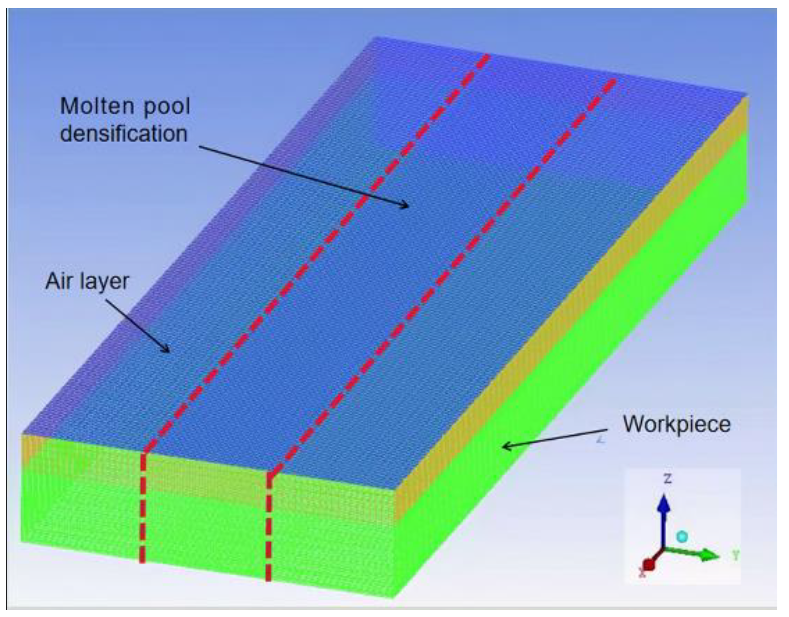
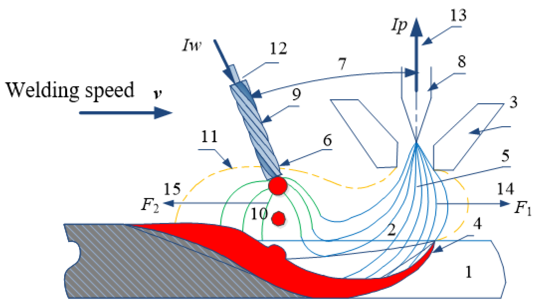
By considering the coupling of heat source pool and the keyhole of PAW-cable-type seven-wire GMAW hybrid welding, three-dimensional numerical analysis models of molten pool flow field, temperature field and plasma induced keyhole have been established based on ANSYS.
(2)
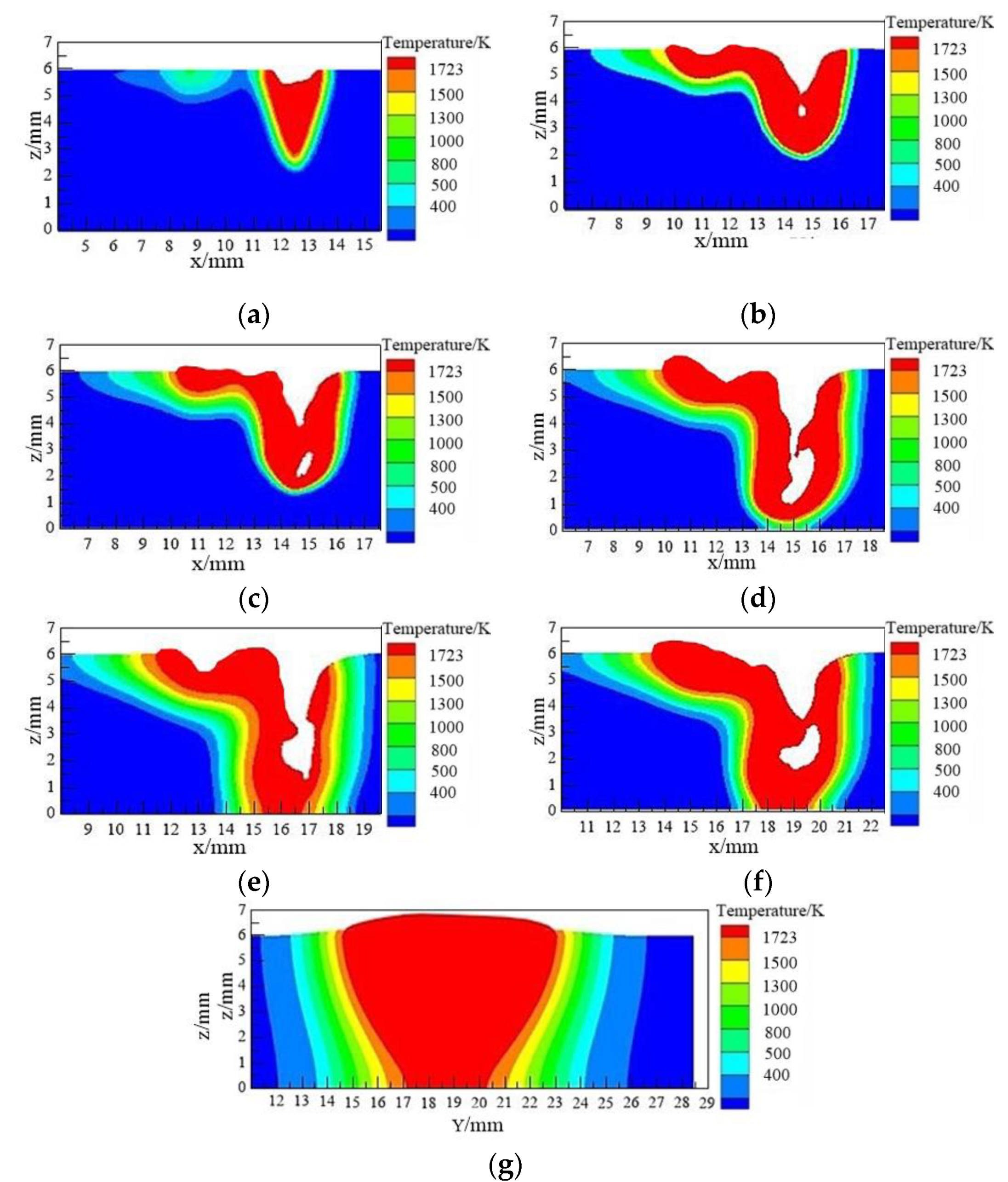
The evolution process of the keyhole in the welding process has been studied by selecting a group of welding parameters and understanding the formation, change and disappearance of keyholes through observing the longitudinal section of a molten pool temperature field at seven different times during welding. Due to the strong penetration ability of plasma arc, the plasma arc forms the “keyhole” in the molten pool during welding. The GMAW arc melts the base metal and the molten metal moves downward to cover the “keyhole”, forming pores under the action of surface tension. The pores float out of the molten pool with the metal in the molten pool.
(3)
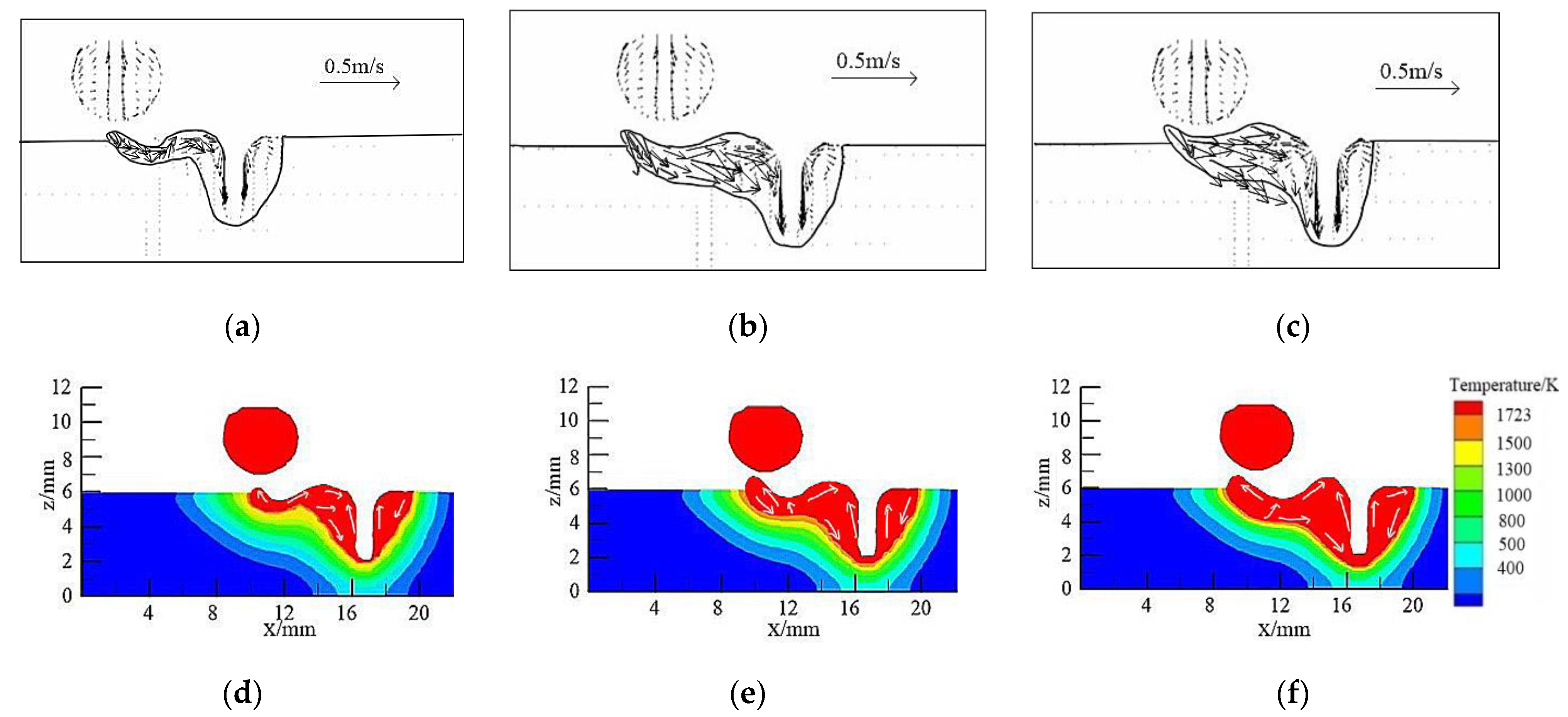
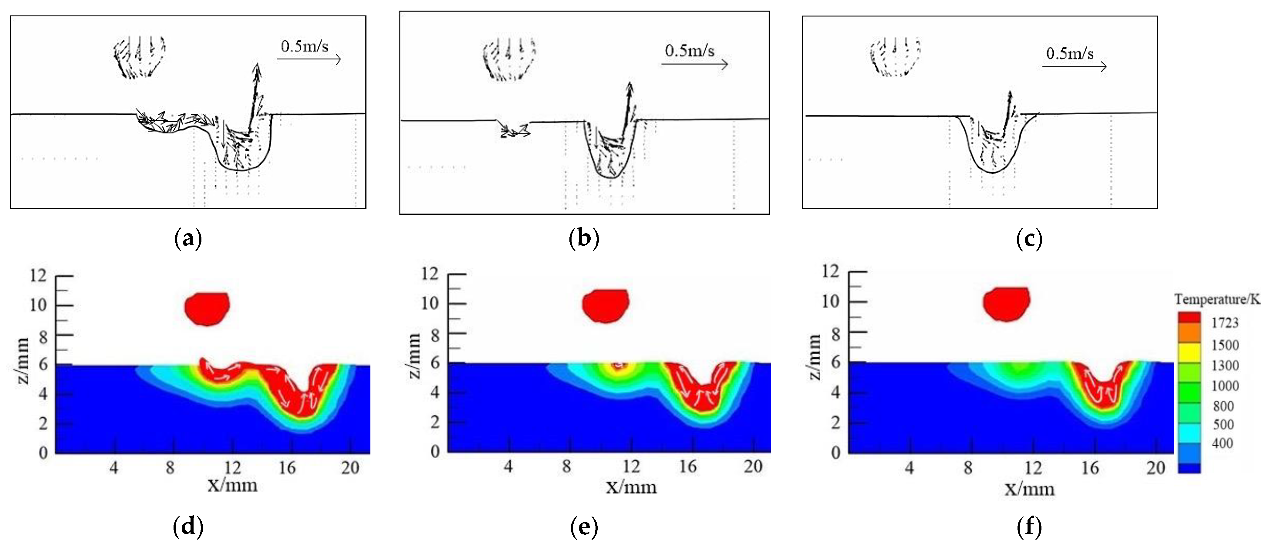
The temperature field and flow field of the weld pool welded with cable welding wire have been simulated, and the effects of GMAW welding current, PAW current and welding speed on the temperature field and flow field of weld pool have been studied, respectively. With the increase of GMAW welding current, both the length and width of the weld pool becomes larger, the volume of the whole weld zone becomes larger, the weld reinforcement becomes higher and the flow rate of molten metal in the pool increases. With the increase of PAW current, the weld pool length increases, the weld reinforcement decreases and the metal flow speed in the weld pool is obviously accelerated. With the increase of welding speed, the weld pool length and fusion depth will decrease, but the reinforcement will first increase and then decrease. Although the metal flow speed in the weld pool decreases, it does not change much.
(4)
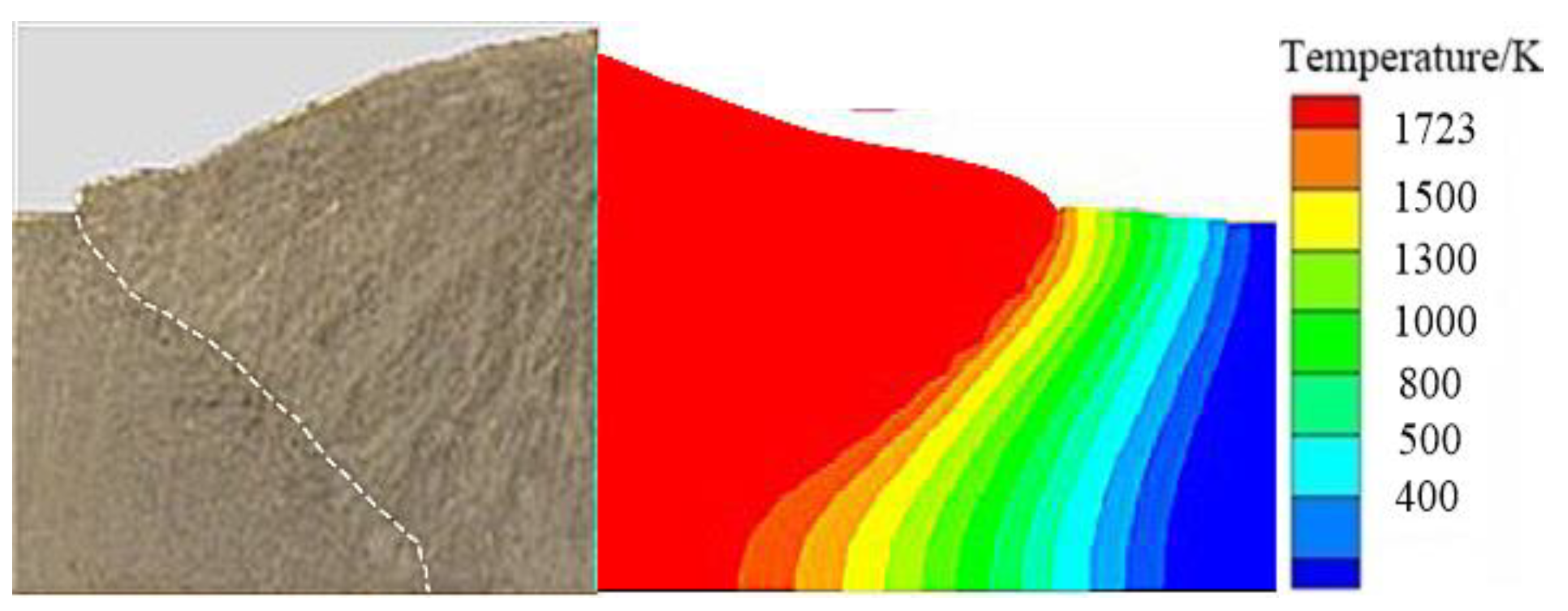
The simulation results are in strong agreement with the test results, verifying the accuracy of the simulation.

Author Contributions

Conceptualization, C.Z. and Q.H.; methodology, C.Z.; validation, C.Z., Q.H. and J.P.; writing—original draft preparation, C.Z. and H.W.; writing—review and editing, C.Z., Q.H. and J.P. All authors have read and agreed to the published version of the manuscript.

Funding

This work is sponsored by the National Natural Science Foundation of China (No. 51675249), Changzhou Science and Technology Plan Project (No.CJ20190028), Natural Science Research General Project of Jiangsu Province (No.19KJB46001) and the Excellent Scientific and Technological Innovation Team of Universities in Jiangsu Province.

Institutional Review Board Statement

Not applicable.

Informed Consent Statement

Not applicable.

Data Availability Statement

The data used to support the findings of this study are available from the corresponding authors upon request.

Acknowledgments

Thank Chengdu Tianqi Wanfeng Electromechanical Equipment Co., Ltd. for providing equipment.

Conflicts of Interest

The authors declare no conflict of interest.

References

  1. Lin, S.B.; Fan, C.L.; Yang, C.L. Efficient Welding Method; Mechanical Industry Press: Beijing, China, 2012. (In Chinese) [Google Scholar]
  2. Wu, C.S.; Wang, L.; Chen, J. Development of high-efficiency modification of arc welding process. Weld. Join. 2013, 8, 1–10. (In Chinese) [Google Scholar]
  3. Essers, W.G.; Liefkens, A.C. Plasma-MIG welding developed by Philips. Mach. Prod. Eng. 1972, 121, 631–634. [Google Scholar]
  4. Que, F.H.; Wang, Z.M. Research progress in the plasma-MIG welding. Electr. Weld. Mach. 2013, 43, 28–32. (In Chinese) [Google Scholar]
  5. Essers, W.G.; Jelmorini, G.; Tichelaar, G.W. Arc characteristics and metal transfer with plasma-MIG welding. Met. Constr. 1972, 4, 439–447. [Google Scholar]
  6. Wang, C.C. Brand new technical breakthrough—Plasma MIG composite welding process. Mod. Weld. Technol. 2010, 11, J18–J22, J25. (In Chinese) [Google Scholar]
  7. Zhou, H.Y. Multi-Arc Rotating Coupling Arc and Temperature Field of CO2 Gas Shielded Welding of Cable Welding Wire; Jiangsu University of Science and Technology: Zhenjiang, China, 2012. (In Chinese) [Google Scholar]
  8. Hu, X.G. Study on Cladding Characteristics and Joint Properties of CO2 Gas Shielded Welding Wire; Jiangsu University of Science and Technology: Zhenjiang, China, 2012. (In Chinese) [Google Scholar]
  9. Fang, C.; Chen, Z.; Xu, G.; Hu, Q.; Zhou, H.; Shi, Z. Study on the process of CTWW CO2 gas shielded welding. Acta Metall. Sinca 2012, 48, 1299–1305. (In Chinese) [Google Scholar] [CrossRef]
  10. Zhang, Y.S.; Dong, X.Q.; Li, D.Y. Analysis on the welding pool geometry under the action of double-arc of plasma-MIG welding. Weld. Technol. 2005, 34, 21–22. (In Chinese) [Google Scholar]
  11. Zhang, Y.S.; Cai, J.; Li, D.Y.; Dong, X.Q. Infinity element analyzed of plasma-MIG welding temperature field. J. Shenyang Univ. Technol. 2004, 26, 258–260. (In Chinese) [Google Scholar]
  12. Hertel, M.; Füssel, U.; Schnik, M. Numerical simulation of the plasma-MIG process-interactions of the arcs, droplet detachment and weld pool formation. Weld. World 2014, 58, 85–92. [Google Scholar] [CrossRef]
  13. Wei, B. Research on Hybrid Palsma-Mig Welding Progress of Aluminum Alloys. Master’s Thesis, Southwest Jiaotong University, Chengdu, China, 2014. (In Chinese). [Google Scholar]
  14. Huo, H.L. Research on Hybrid Palsma-Mig Welding Progress of Medium Thickness Plate Aluminum Alloys. Master’s Thesis, Southwest Jiaotong University, Chengdu, China, 2014. (In Chinese). [Google Scholar]
  15. Piao, S.J.; Jin, C. Numerical simulation of arc and molten pool of plasma-MIG/MAG hybrid welding. Hot Work. Technol. 2016, 45, 202–205, 209. (In Chinese) [Google Scholar]
  16. Piao, S.J. Numerical Simulation of Arc and Weld Pool Temperature Field in Plasma-MIG/MAG Hybrid Welding; Dalian University of Technology: Dalian, China, 2016. (In Chinese) [Google Scholar]
  17. Shi, Z.; Lu, X.H. Large Diameter Stranded Flux Cored Wire. CN201677141U, 22 December 2010. (In Chinese). [Google Scholar]
  18. Shi, Z.; Lu, X.H. A Manufacturing Method of Large Diameter Carbon Dioxide Protected Stranded Welding Wire. CN101885118A, 17 November 2010. (In Chinese). [Google Scholar]
  19. Leng, H.K. Study on Narrow Gap Double-Cable-Wire GMAW Welding Pool Fluid Behaviors; Jiangsu University of Science and Technology: Zhenjiang, China, 2017. (In Chinese) [Google Scholar]
  20. Zhang, T.; Wu, C.S.; Feng, Y.H. Numerical analysis of heat transfer and fluid flow in keyhole plasma arc welding. Numer. Heat Transf. Part A Appl. 2011, 60, 685–698. [Google Scholar] [CrossRef]
  21. Goldak, J.; Chakravarti, A.; Bibby, M. A new finite element model for welding heat sources. Metall. Trans. B 1984, 15, 299–305. [Google Scholar] [CrossRef]
  22. Xu, G.X.; Wu, C.S.; Qin, G.L.; Wang, X.Y.; Lin, S.Y. Adaptive volumetric heat source models for laser beam and laser + pulsed GMAW hybrid welding processes. Int. J. Adv. Manuf. Technol. 2011, 57, 245–255. [Google Scholar] [CrossRef]
  23. Xu, G.; Wu, C.; Ma, X.; Wang, X. Numerical analysis of welding residual stress and distortion in laser+GMAW hybrid welding of aluminum alloy T-joint. Acta Met. Sin. 2013, 26, 352–360. [Google Scholar] [CrossRef]
  24. Zhang, T.; Wu, C.S. Numerical simulation of temperature field and fluid flow in keyhole plasma arc welding. Trans. China Weld. Inst. 2011, 32, 87–90. (In Chinese) [Google Scholar]
Figure 1. Schematic diagram of the paraxial plasma- cable-type seven-wire GMAW hybrid welding [9]. Note: 1-workpiece, 2-plasma flow, 3-plasma nozzle, 4-molten metal, 5-plasma arc center, 6-welding wire center, 7-angle between electrodes, 8-tungsten electrode, 9-welding wire, 10-GMAW welding arc, 11-plasma, 12-welding wire current (IW) direction, 13-PAW current (IP) direction, 14-electromagnetic force applied to PAW arc (F1), 15-electromagnetic force applied to GMAW arc (F2).
Crystals 12 00306 g001
Figure 2. The workpiece meshing diagram.
Crystals 12 00306 g002
Figure 3. Temperature field distribution of weld pool at different welding times. (a) temperature field at 0.11 s. (b) temperature field at 0.23 s. (c) temperature field at 0.28 s. (d) temperature field at 0.36 s. (e) temperature field at 0.54 s. (f) temperature field at 0.71 s. (g) temperature field at 0.98 s (weld cross-sectional view).
Crystals 12 00306 g003
Figure 4. The fluid field and temperature field distribution of xoy surface at 0.25 s. (a) fluid field at 280 A. (b) fluid field at 320 A. (c) fluid field at 340 A. (d) temperature field at 280 A. (e) temperature field at 320 A. (f) temperature field at 340 A.
Crystals 12 00306 g004
Figure 5. The fluid field and temperature field distribution of xoy surface at 0.71 s. (a) fluid field at 240 A. (b) fluid field at 260 A. (c) fluid field at 280 A. (d) temperature field at 240 A. (e) temperature field at 260 A. (f) temperature field at 280 A.
Crystals 12 00306 g005
Figure 6. The fluid field distribution of xoy surface at 0.14 s. (a) fluid field at 0.5 m/min. (b) fluid field at 0.6 m/min. (c) fluid field at 0.7 m/min. (d) temperature field at 0.5 m/min. (e) temperature field at 0.6 m/min. (f) temperature field at 0.7 m/min.
Crystals 12 00306 g006
Figure 7. Comparison of the simulated results with the actual weld section morphology.
Crystals 12 00306 g007
Table 1. Chemical compositions of the welding wire and Q235B (unit: wt.%).
MaterialCMnSiSPNiCrMoVCuFe
ER50-60.06–0.151.4–1.850.8–1.15≤0.025≤0.025≤0.15≤0.15≤0.15≤0.03≤0.5Balanced
Q235B0.12–0.200.3–0.67≤0.3≤0.045≤0.045Balanced
Table 2. Welding parameters.
No.GMAW Welding Current I1
/A
PAW Current I2
/A
Plasma Flow Rate P(G)
/L·min—1
Welding Speed v
/m·min—1
12802802.00.5
22802802.00.6
32802802.00.7
43202802.00.5
53402802.00.5
63402602.00.5
73402402.00.5
Table 3. Material thermophysical properties.
Temperature T/KThermal Conductivity ×103/(W/mK)Density × 103 /(kg/m3)Specific Heat Capacity /(J/kgK)
2930.0507.80460
5230.0477.70480
7730.0407.61530
10230.0277.55675
12730.0307.49670
17730.0357.35660
19730.1507.30780
Publisher’s Note: MDPI stays neutral with regard to jurisdictional claims in published maps and institutional affiliations.

