Article

Surface Modification with Phosphate and Hydroxyapatite of Porous Magnesium Scaffolds Fabricated by Binder Jet Additive Manufacturing

1
Additive Manufacturing Division, Singapore Institute of Manufacturing Technology (SIMTech), Agency for Science, Technology and Research (A*STAR), 5 Cleantech Loop, Singapore 636732, Singapore
2
Department of Materials Science and Engineering, National University of Singapore, 9 Engineering Drive 1, Singapore 117575, Singapore
*
Authors to whom correspondence should be addressed.
Crystals 2022, 12(12), 1850; https://doi.org/10.3390/cryst12121850
Submission received: 27 November 2022 / Revised: 12 December 2022 / Accepted: 16 December 2022 / Published: 19 December 2022
(This article belongs to the Special Issue State-of-the-Art Magnesium Alloys)

Abstract

:
The presence of porosity within magnesium-based orthopaedic implants is known to be beneficial, promoting cell proliferation and vascularisation. However, the presence of porosity increases the surface area available for corrosion, compounding the issue of high corrosion rates which has long been plaguing magnesium-based materials. This work looks at the influence of hydroxyapatite and phosphate conversion coatings on the corrosion performance of conventionally cast, dense Mg-Zn-Zr alloys and binder jet additive manufactured porous Mg-Zn-Zr scaffolds. The performance of coating on dense Mg-Zn-Zr was found to be more effective than the coating on the porous Mg-Zn-Zr scaffold, with the discrepancies attributed to both the microstructure and geometric influence of the binder jet additive manufactured, porous Mg-Zn-Zr scaffold, which not only increases the rate of hydrogen evolution but also reduces the ability of the hydrogen gas generated within the pore channels to escape to the sample’s surface. This restricts the effectiveness of coating application for porous Mg scaffold. Furthermore, the limited diffusion within the pore channels can also result in differing localized corrosion environments, causing discrepancies between the localised corrosion environment within the pore channels and that at the bulk electrolyte.

1. Introduction

The prominent emergence of 3-dimensional (3D) porous structures in recent times cannot be overlooked, providing a special niche for applications. For orthopaedic applications, 3D porous structures are often deemed as an essential property for tissue scaffold engineering [1], which is well known to improve cell proliferation [2] and vascularisation [3]. In recent times, research into magnesium-based 3D porous structures has been gaining traction, due to their well-known biocompatibility and biodegradability [4,5,6,7]. The ability of such Mg porous structures to release essential bodily nutrients during service has also been proposed to aid in the healing process [8]. However, the relatively high degradation rate of Mg has always been its Achilles heel, which is compounded by the increased surface area of any 3D porous structure [9,10], which further increases corrosion. The reduction in the corrosion rate of Mg can be achieved either through material design [11,12] and/or the application of coatings [13].
The coatings for Mg often specifically target a single property or a combination of properties, typically in the form of improved chemical and/or mechanical properties of the Mg substrate [14,15,16]. Research into coating technologies can be separated into two main categories, the type of coatings and their application techniques. Coatings for biomedical Mg alloys often are phosphate [6,17,18,19] or hydroxyapatite [6,20,21] based due to their demonstrated good bone compatibility [6] and osteogenesis [22]. Similarly, the coating application techniques used on Mg can also be physical (e.g., cold sprayed) [23,24], electrodeposited [21,25], or chemical [20,26] based. The majority of the coating formulation and application techniques target 2-dimensional (2D) structures, i.e., flat substrates [27,28]. When dealing with coating applications on porous structures with micron-sized pores, the lack of line-of-sight for the physical spraying method or the limited reach of the electric field during electrodeposition can result in the coating only having a limited penetration depth into the porous structure. This limits the available coating techniques. Shirokova et al. [29] demonstrated the potential of vacuum infiltration of the coating of porous titanium and nickel structures; however, its effectiveness on corrosion has yet to be investigated, especially when applied to porous Mg structures. With studies on the corrosion protection of porous Mg structures or scaffolds [26,30] remaining limited, the performance of coatings during the transfer of formulation from dense to porous structure remains of great interest.
The performance of the different coatings can be determined by electrochemical corrosion testing. Often, the preferred method of testing choice is potentiodynamic polarisation [20], due to its ability to provide informative insights into the change in the cathodic and anodic kinetics of the coating. Alternatively, measurement of the rate of hydrogen evolution from the coated sample [31,32] can also be carried out for the corrosion of coatings targeting biomedical applications. However, the shortcomings of hydrogen evolution measurements are apparent, as they provide only a limited understanding of the corrosion kinetics mechanisms [33]. Although the potentiodynamic polarisation testing of coated porous structures (scaffolds) has been attempted [26], it was reported that the penetration of the electric field into porous structures is limited [34]. As such, the effectiveness and results of the potentiodynamic polarisation when used for the determination of a 3D porous scaffold are limited.
Conventional manufacturing technologies based on powder metallurgy and casting have been used to fabricate the porous structures of Mg alloys [35,36,37,38]. These conventional approaches are useful within their boundaries. However, their applications are restricted by the limitations of conventional manufacturing methods to produce porous Mg structures with simple geometry. These restrictions are targets to be addressed by additive manufacturing technologies. In previous studies [39,40,41,42], we developed the binder-jet additive manufacturing method for fabricating interconnected porous Mg structures. This study aimed to conduct a comparative study between the corrosion characteristics of Mg alloys in 3D (3D printed porous Mg-Zn-Zr scaffolds) and 2D structures (dense Mg-Zn-Zr substrate). In this regard, electrodeless deposition and conversion coating techniques were used to form/deposit hydroxyapatite and phosphate-based conversion coating on dense Mg substrates (2D structure) and binder-jet printed porous scaffolds (3D structure). Then, the corrosion performance of these structures was investigated using potentiodynamic polarisation (for 2D Mg-Zn-Zr substrate) and hydrogen evolution measurements (for 3D porous Mg-Zn-Zr scaffold).

2. Materials and Methods

2.1. Fabrication of Dense and Porous Mg Samples

In this work, the 2D, dense Mg-Zn-Zr alloy samples for coating application were gravity cast in steel moulds at 750 °C; after cooling, the oxide-coated surface layer was machined away. Binder jetting was used to fabricate the porous samples. Detailed descriptions of the binder jetting and sintering of Mg alloys can be found in our earlier work [39,40,41,42]. The printed green sample was then sintered at the elevated temperature of 615 °C. The microstructure and composition of both the as-casted and binder jet printed (BJP) Mg-Zn-Zr sample will be reported in the results section.

2.2. Coating of Dense and Porous Mg Samples

A solution of hydroxyapatite (HA) was prepared using a precipitation method [29]. Five volume parts of 0.02 M calcium hydroxide (Ca(OH)2) were mixed with one volume part of 0.07 M phosphoric acid (H3PO4). The mixture was left to mix and precipitate on a magnetic stirring plate for 1 h, allowing the hydroxyapatite to precipitate. The precipitated hydroxyapatite was then rinsed and filtered before an equal volume was evenly spread on the surfaces of the dense Mg-Zn-Zr samples. The surfaces of the dense Mg-Zn-Zr samples were sequentially ground until they reached 1200 grit prior to coating applications. The different batches of hydroxyapatite-coated samples were dried at different temperatures of 25 °C, 40 °C, 55 °C, and 100 °C in a temperature-regulated oven.
Similarly, a series of stock solutions containing H3PO4 and magnesium hydroxide (Mg(OH)2) was also prepared. The eventual stock solutions contained 0.1 M Mg(OH)2, with varying concentrations of H3PO4 (0.12 M, 0.16 M, and 0.24 M). The pH of the stock solutions was determined to be approximately 5.15, 3.48, and 2.62, respectively. The samples were immersed in the stock solution for a duration of 1 h, eventually removed, rinsed with deionised water, and dried with nitrogen gas.
For the coating of porous Mg-Zn-Zr scaffolds, the use of a vacuum pump was introduced. The vacuum pump removes the air from the pore channels of the porous substrate. With the release of vacuum, a negative pressure is generated within the pores of the porous substrate, which allows the atmospheric pressure to aid penetrating the coating deeper into the pore channels. The use of the vacuum pump aided the penetration of the stock solutions (both HA and phosphate conversion coating) into the interconnected porous structure of Mg-Zn-Zr scaffolds. The processing steps of the coating process remained the same for consistency.

2.3. Materials Characterisation

SEM and EDX characterisations were conducted with a Zeiss Sigma 300 Fe-SEM (Zeiss, Oberkochen, Germany), with an accelerating voltage of 15 keV. Phase composition was obtained using a Bruker D8 Discover XRD (Bruker, Billerica, MA, USA) with Cu-kα radiation (λ = 1.5418 A). The XRD profiles were collected in step sizes of 0.1°, with a dwell time of 3 s. The elemental composition of the samples was determined with a Perkin Elmer Optima 4300 DV (PerkinElmer, Waltham, MA, USA) inductive coupled plasma optical emission spectroscopy (ICP-OES), with the oxygen content determined with inert gas fusion infrared absorbance. The densities of the dense and porous specimens were measured by Archimedes’ principle, according to ASTM B962. The internal structure of the porous Mg-Zn-Zr scaffold was characterised by Nanotom M180 X-ray (General Electric, Boston, MA, USA) computed tomography system (XCT), with a resolution of 3.5 µm. The post-processing of the tomograms was done with computational analysis software provided by the system.

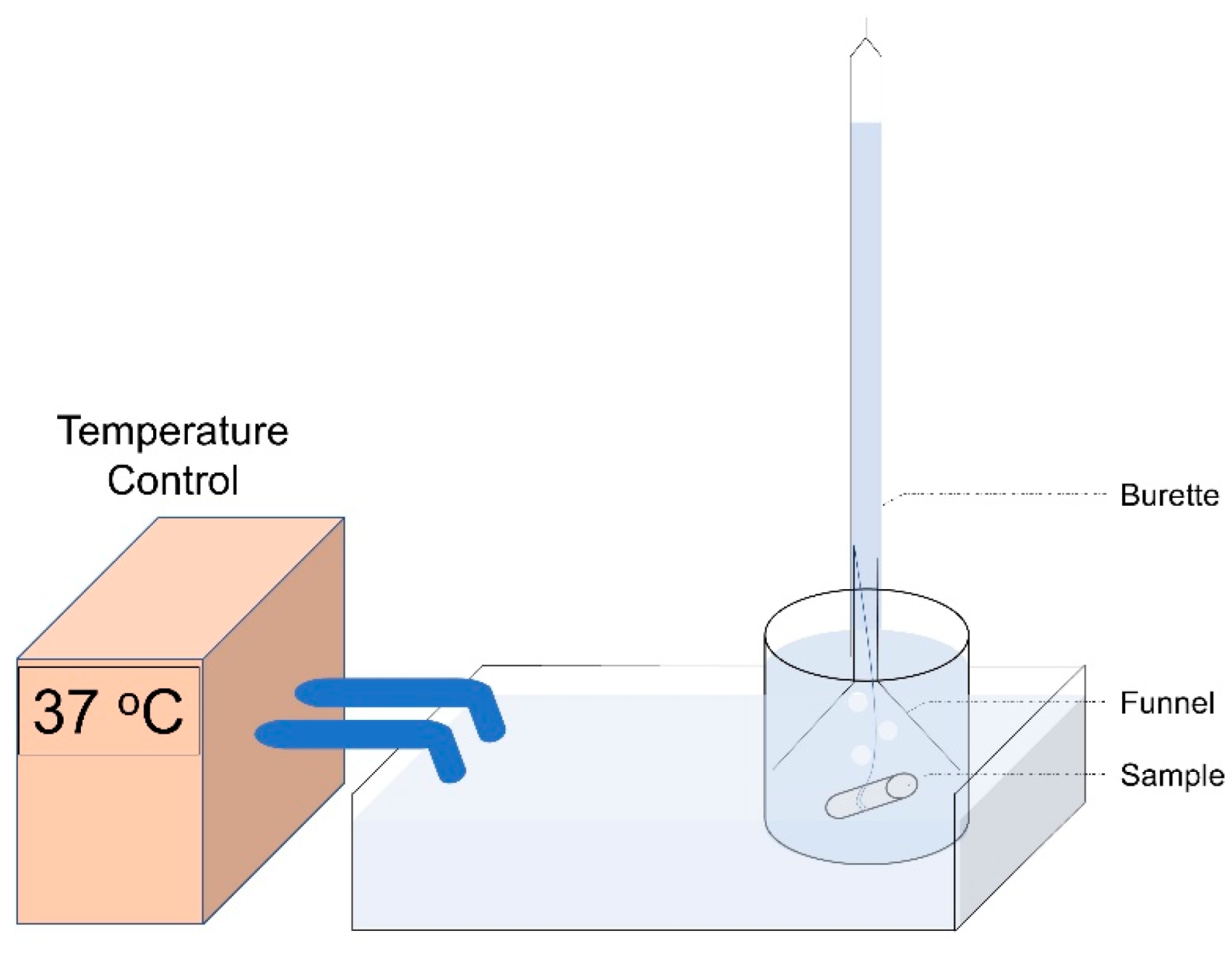
2.4. Corrosion Study

The corrosion performance of the coated and uncoated dense Mg samples was investigated in 0.1 M sodium chloride. Afterward, for 30 min under open-circuit conditions, potentiodynamic polarisation tests were carried out at a scan speed of 1 mV s−1 against a saturated calomel reference electrode (SCE) with a graphite rod counter electrode. The corrosion performance of the coated and uncoated 3D porous scaffold was investigated through hydrogen evolution measurements. The hydrogen evolution measurement was carried out in Phosphate Buffered Saline (PBS), maintained at 37 °C using a water bath. Figure 1 shows a schematic of the hydrogen evolution setup, consisting of an inverted funnel and burette, similar to the one proposed in the work of Song et al. [43].

3. Results and Discussions

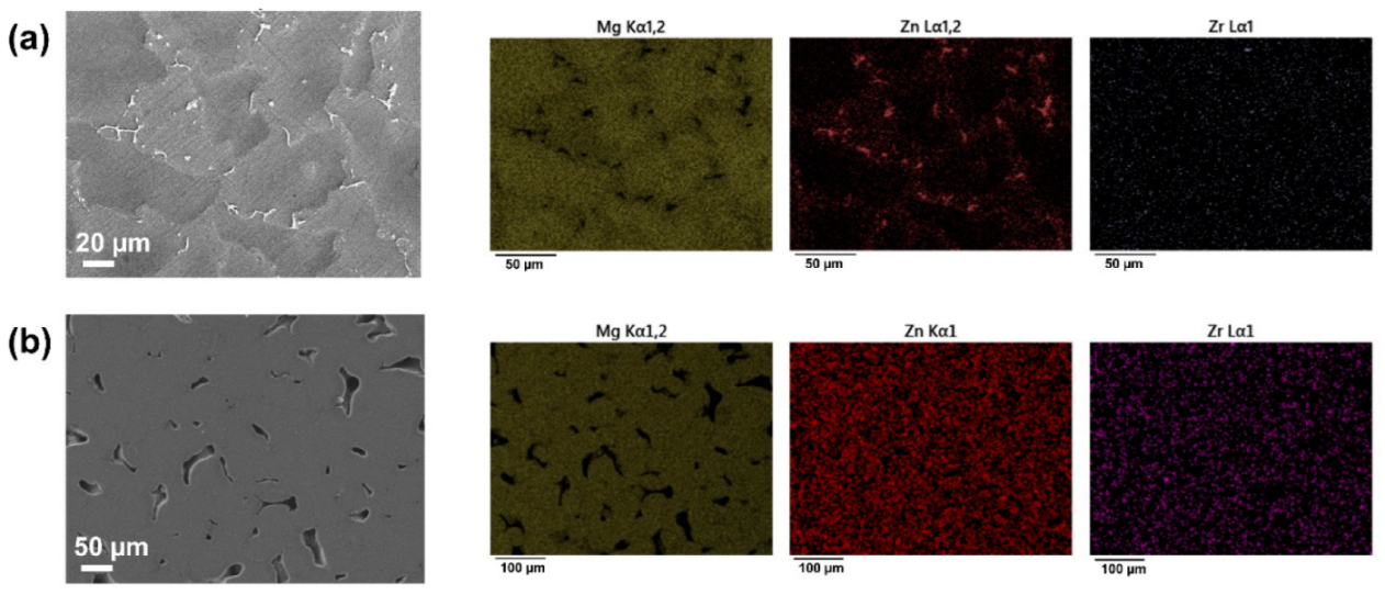
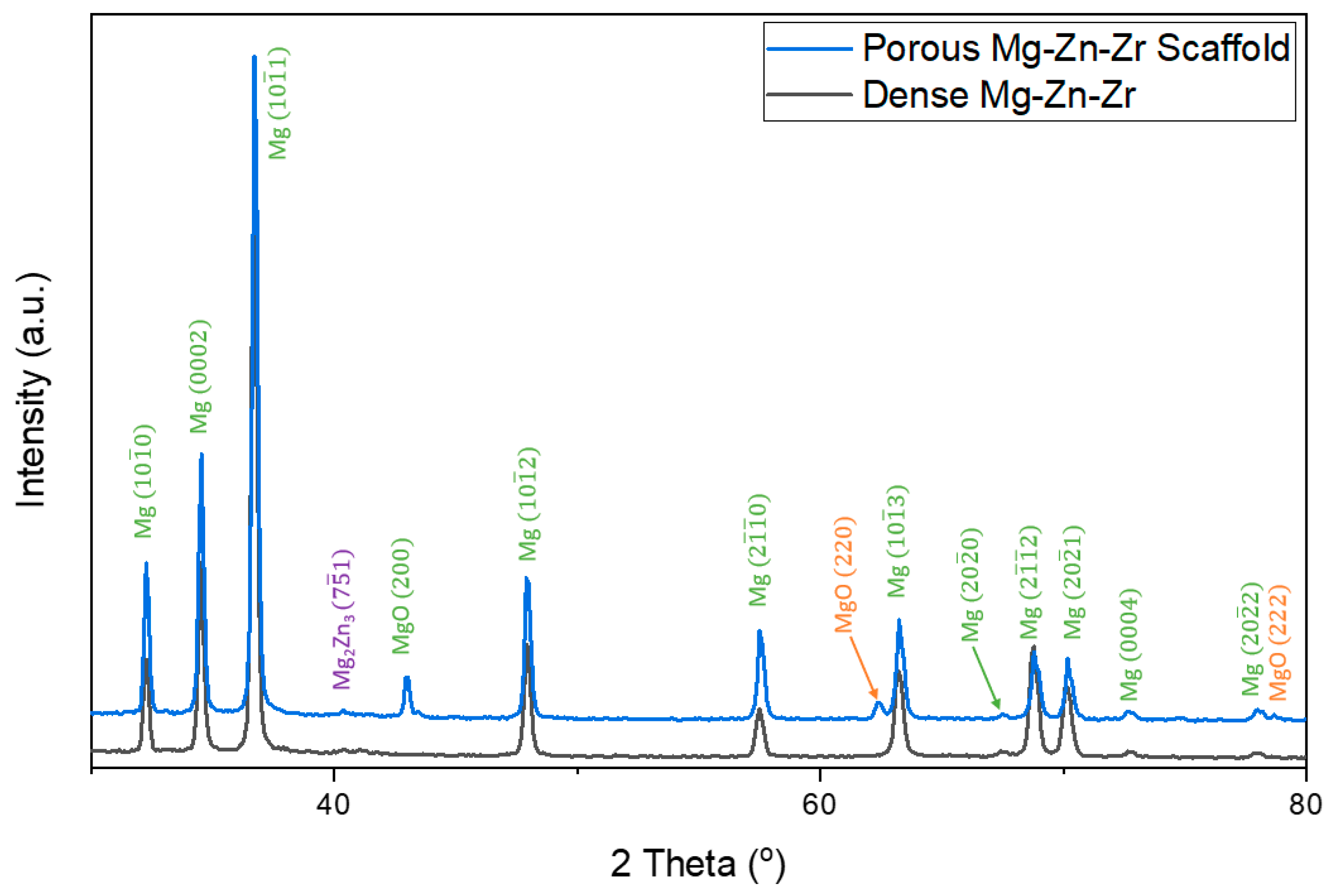
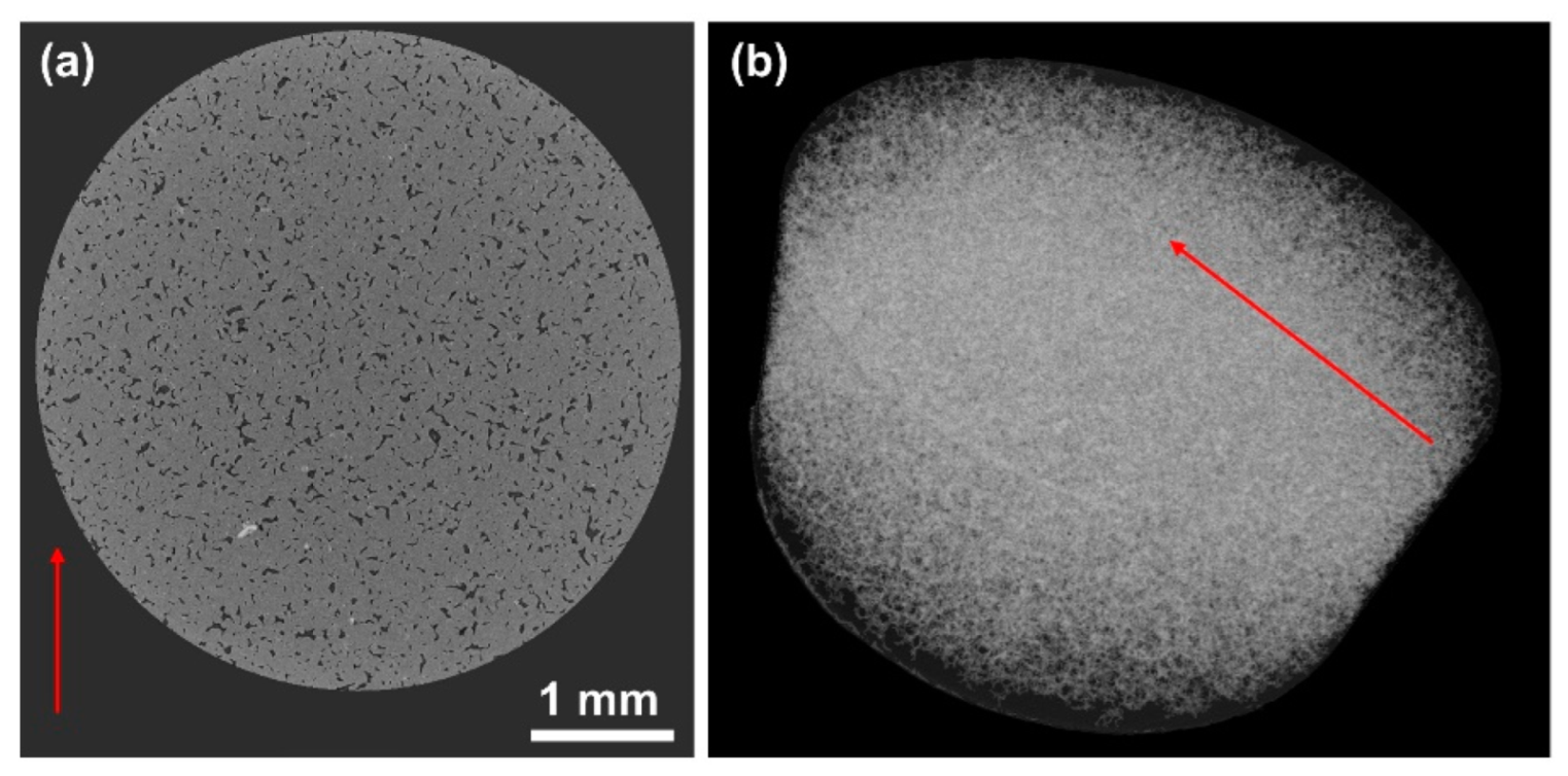
3.1. Characterisation of Dense and Porous Mg-Zn-Zr Samples

Figure 2a shows SEM and EDX images of a polished cross-section of the dense Mg-Zn-Zr sample. The dense Mg-Zn-Zr sample demonstrates a microstructure with precipitation of zinc-rich secondary phases along the grain boundaries of Mg-rich matrices. Table 1 shows the elemental composition of the as-casted Mg-Zn-Zr alloy, determined from ICP-OES to be 5.49 wt.% Zn, 0.73 wt.% Zr, and Bal. Mg.
Figure 2b shows SEM and EDX images of a cross-section of the porous Mg-Zn-Zr scaffold manufactured via binder jet additive manufacturing. Its cross-sectional microstructure demonstrated evenly distributed pores with evenly dispersed elements of magnesium, zinc, and zirconium. The oxygen-rich regions correspond to MgO; identified later via XRD (Figure 3b). These MgO inclusions were introduced during the high-temperature sintering of the green samples, which oxidises the surface of the Mg powders [44,45]. Table 1 shows the elemental composition of the BJP Mg alloy, determined from ICP-OES and inert gas fusion infrared absorbance. The composition is reported to be 5.16 wt.% Zn, 0.18 wt.% Zr, 0.12 wt.% O, and Bal. Mg. The chemical composition of the porous Mg-Zn-Zr scaffold manufactured via binder jet additive manufacturing is similar to that of the dense Mg-Zn-Zr sample provided in the same table. One subtle difference in the elemental compositions is in the zirconium concentration, with the dense Mg-Zn-Zr sample having a higher (0.73 vs. 0.18 wt%) concentration of zirconium than the porous Mg-Zn-Zr scaffold. The addition of zirconium is known to serve as a grain refiner [46] during the manufacturing process of Mg. It is also known to possibly worsen (increase) the corrosion rate of Mg-based alloys due to the formation of zirconium secondary phases [47]. Zinc is added to the Mg matrix for mechanical properties, in particular, it has an age-hardening effect [48,49]. Similar to Zr, the formation of MgxZny secondary phases is also known to serve as local cathodes during the corrosion of Mg [46]. This means that an increase in the Zn concentration can decrease the overall corrosion resistance of the Mg alloy due to detrimental galvanic interactions from the increased MgxZny secondary phase formation. However, this paper does not intend to discuss the difference in the corrosion mechanisms of the base sample.
Figure 3 shows the phase composition of a dense Mg-Zn-Zr sample. The phases available in the microstructure of Mg-Zn-Zr are also confirmed to consist of α-Mg and minute Mg2Zn3 secondary phases, which are believed to be the identities of the magnesium and zinc-rich regions identified in the EDX (Figure 2a). Figure 3 also shows the XRD pattern of the BJP Mg-Zn-Zr alloy, from which can be derived that the main phase constituents are α-Mg matrix, Mg2Zn3 secondary phase, and MgO inclusions. The MgO inclusions originate from the sintering process and are incorporated within the microstructure during the sintering process, as previously mentioned. From the ratios of the α-Mg and Mg2Zn3 peaks in Figure 3, it can be concluded that the fraction of the secondary phase in the dense and porous samples is approximately the same. Thus, other than the MgO, the phase composition of the porous and dense Mg-Zn-Zr samples can be considered almost identical.
Archimedes’ density of the dense and porous samples was measured to be 99.5% and 87%. Figure 4 shows the 3D reconstruction of the porous Mg-Zn-Zr scaffold manufactured via binder jet additive manufacturing. The computational software analysis shows that the pore channels within the structure can be characterised, with the relative porosity being approximately 13%, possessing an open porosity index of >95%. With open porosity of the porous Mg-Zn-Zr scaffold >95%, the electrolytes are aided (through a vacuum) into the interconnected pore channels, before being deposited on the internal walls of the porous structure, either through precipitation (in the case of HA) or conversion (phosphate conversion coating), achieving corrosion protection.

3.2. Coating of Dense Samples

As there is still excess liquid upon applying the stock solution on the sample’s surface, removing an excess solvent is necessary. Variations in drying temperature have been known to influence the corrosion protection properties of coatings due to the potential to form microcracks at high drying temperatures [50]. To investigate the influence of drying temperature on the corrosion properties of the applied HA coating, the dense Mg-Zn-Zr samples were coated with the same stock solution of HA and dried at temperatures of 25 °C, 40 °C, 55 °C, and 100 °C. Similarly, differences in the composition of the initial stock phosphate solution prior to the application of the conversion coating are known to induce variations in the properties of the final coated samples [27,28]. To investigate the influence of initial H3PO4 concentration on the corrosion protection properties of the applied phosphate conversion coatings, these were coated on dense Mg-Zn-Zr samples using initial concentrations of H3PO4 varying from 0.12 M, 0.16 M to 0.24 M.
Figure 5 shows SEM images of the HA (dried at 25 °C) and phosphate conversion (0.12 M, 0.16 M, and 0.24 M) coated samples. From the morphology of both the HA and phosphate conversion coated surfaces the coatings appear to be generally uniform across the surface, despite the observation of some microcracks on the coatings. Although it is known that a thicker coating layer can provide a better barrier against corrosion, thicker coatings have a greater tendency to crack (Figure 5) which nullifies the benefits of increased thickness. As such, the optimization of the process parameters can be seen as a means to minimize the influence of cracks on corrosion performance instead of varying the coating thickness to optimize corrosion performance. In view of this, the coating thicknesses were not measured. The corrosion performance of these coated samples is explored in more detail in the following section.

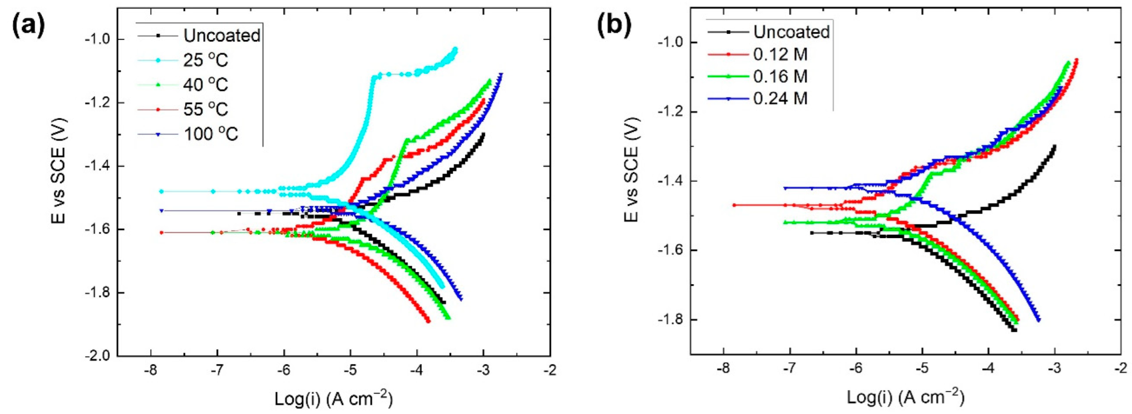
3.3. Corrosion of Coated Dense Samples

3.3.1. Hydroxyapatite Coating

Figure 6a shows potentiodynamic polarisation curves for HA-coated dense Mg-Zn-Zr samples in 0.1 M sodium chloride. The polarisation curves were obtained after a 30 min immersion at open circuit potential, with a scan rate of 1 mV s−1. The corrosion current densities obtained from Tafel extrapolation of the potentiodynamic polarisations curves are tabulated in Table 2. The polarisation curve of the uncoated Mg-Zn-Zr sample (with a measured current density of 1.5 × 10⁻⁵ A cm−2) is provided as a reference. It is observed that the drying temperature of the HA coating in this work does not have a direct correlation to the measured corrosion current density. The measured current varied from 5.0 × 10⁻⁶ A cm−2 when dried at 25 °C, to 5.26 × 10⁻⁵ A cm−2 when dried at 40 °C, and 6.2 × 10⁻⁶ A cm−2 when dried at 55 °C and 2.2 × 10⁻⁵ A cm−2 when dried at 100 °C. The corrosion performance of HA coating dried at 25 °C appeared to be optimal for the coating of dense Mg-Zn-Zr sample, with this sample having both the lowest corrosion current recorded and a positive shift in its pitting potential relative to the HA coatings prepared with other parameters. As previously hypothesised, the drying temperature played an important role in the determination of the corrosion protection of the HA coating. An inappropriate coating processing parameter resulted in detrimental corrosion performance relative to the uncoated Mg-Zn-Zr sample (i.e., the samples dry at 40 °C and 100 °C).
When comparing the corrosion performance of the HA coating via the precipitation method on a dense Mg-Zn-Zr sample dried at 25 °C with the conversion-based HA coating method reported in another work by Chen et al. [20], a 16~22x reduction in corrosion current density (of coated vs. uncoated) was reported after a successful conversion coating with HA/Mg(OH)2 on pure Mg. Although only a 3x reduction in current density (of coated vs. uncoated) was observed in this present work, it is worth noting that the eventual measured corrosion current densities reported in the two works are of the same magnitude being 2.7 × 10⁻⁶ A cm−2 in the work of Chen et al. [20] and 5.0 × 10⁻⁶ A cm−2 in the present work. Thus, we translated this electroless precipitation parameter for the surface modification of the interior pores and exterior surface of the porous Mg samples with hydroxyapatite.

3.3.2. Phosphate Conversion Coating

Figure 6b shows the potentiodynamic polarisation curves of the dense Mg-Zn-Zr sample after phosphate conversion coating, in 0.1 M NaCl. The phosphate conversion coating was conducted with stock solutions of premixed H3PO4/Mg(OH)2 with initial concentrations of 0.12 M, 0.16 M, and 0.24 M H3PO4, respectively. The polarisation curves were obtained after 30 min of immersion under open-circuit conditions, with a scan rate of 1 mV s−1. The corrosion current densities obtained from Tafel extrapolation of the potentiodynamic polarisations curves are tabulated in Table 2. Similarly, the polarisation curve of an uncoated Mg-Zn-Zr sample (with a measured current density of 1.5 × 10⁻⁵ A cm−2) is also provided as a reference. The measured current density increases from 3.1 × 10⁻⁶ A cm−2 with an initial H3PO4 concentration of 0.12 M to 4.7 × 10⁻⁶ A cm−2 with an initial concentration of H3PO4 of 0.16 M and 5.9 × 10⁻⁶ A cm−2 with an initial concentration H3PO4 of 0.24 M. It is observed that an increase in the initial concentration of H3PO4 during the coating process led to an increase in the measured corrosion current density. The corrosion performance of phosphate conversion coating with an initial concentration of 0.12 M phosphoric acid appeared to provide better corrosion resistance to the sample, relative to the conversion coatings applied with initial concentrations of either 0.16 M or 0.24 M H3PO4. The result resonates with the previous finding by Jayaraj et al. [27], where a higher pH of the phosphate conversion coating, which was done through a reduction in H3PO4 concentration, improved the corrosion properties of the phosphate conversion coating formed. Comparing the corrosion performance of the phosphate conversion coatings and their effectiveness in reducing the corrosion of the uncoated dense Mg-Zn-Zr alloy, a 4.8× reduction in corrosion current density is found from the phosphate conversion coating in 0.12 M stock H3PO4 solution (relative to the uncoated dense Mg-Zn-Zr alloy). The 4.8× reduction in the corrosion rate post phosphate conversion coating falls within the range reported in the work of Jayaraj et al. [27], where 3 to 15x improvements in corrosion rates were reported from the base AZ31 alloy after phosphate conversion coating. The reported corrosion density of the phosphate conversion coating in 0.12 M (3.1 × 10⁻⁶ A cm−2) is also of the same magnitude as the corrosion current density of the magnesium phosphate conversion coating reported in the works of Phuong et al. (6.3 × 10⁻⁶ A cm−2) [19] and Jayaraj et al. (9 to 49 × 10−6 A cm−2) [27].
Comparing how the optimised HA (dried at 25 °C) and phosphate conversion coating (0.12 M) in this work fare against each other, the potentiodynamic polarisation of uncoated dense Mg-Zn-Zr alloy, HA coating with a drying temperature of 25 °C (Figure 6a) and phosphate conversion coating with an initial concentration of 0.12 M H3PO4 (Figure 6b) are compared. The overall corrosion performance, as determined from the measured corrosion current density, increases in the order uncoated, to HA (25 °C), to phosphoric (0.12 M) conversion coating, with the decreases in the corrosion rates for the coated samples compared to the uncoated sample being a factor of 3.0× for the HA (25 °C) and 4.8× for the phosphoric conversion (0.12 M) coated samples (Table 2). Although the phosphoric conversion (0.12 M) coated sample displayed the lowest corrosion current density the HA (25 °C) coated Mg-Zn-Zr sample had the most positive pitting potential of the three dense Mg-Zn-Zr samples; i.e., the HA (25 °C) coating provided the best protection against localized pitting corrosion.

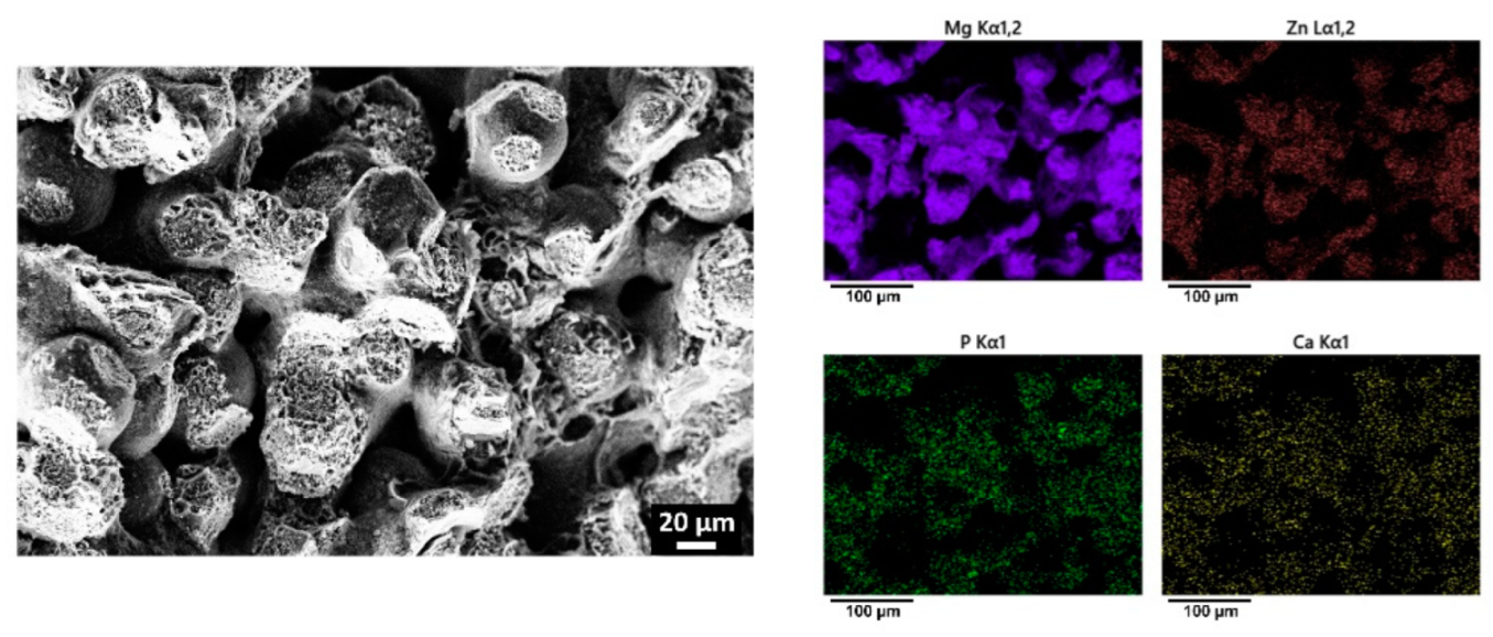
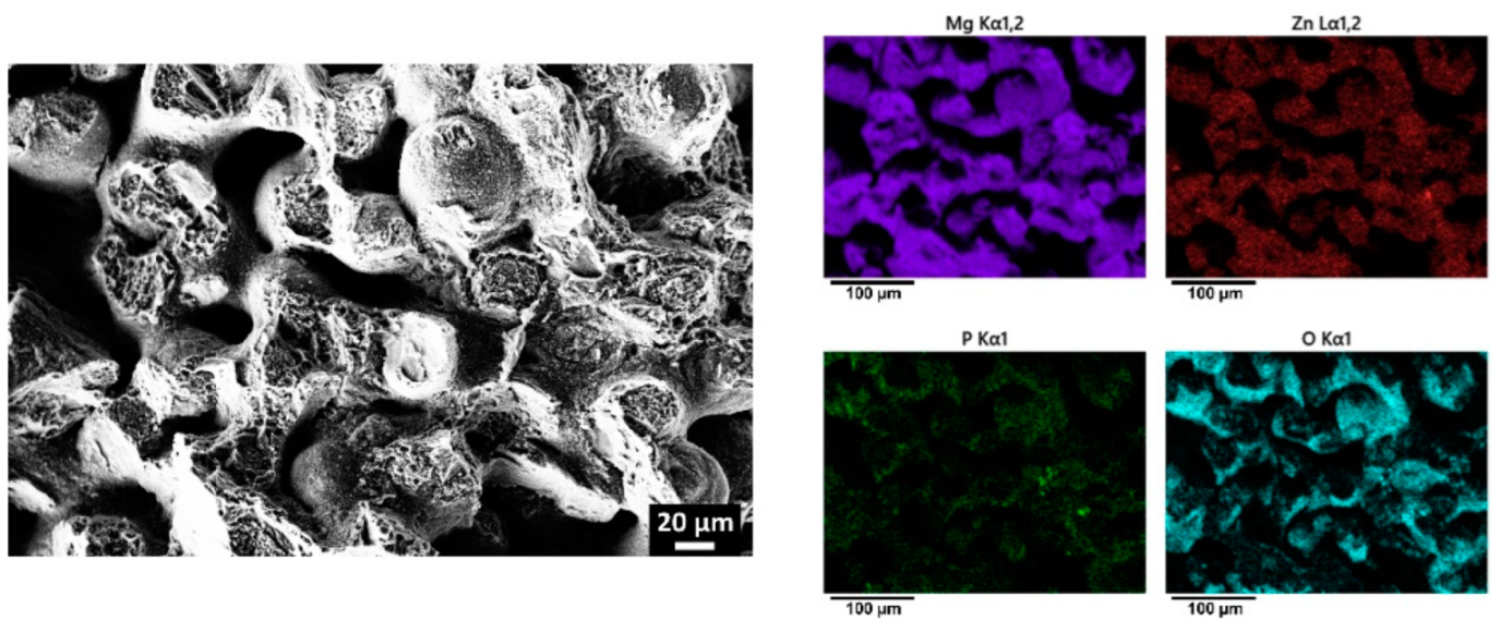
3.4. Coating of Porous Mg-Zn-Zr Scaffolds

From the studies on both the coating process optimisation and corrosion performance, both HA (25 °C) and phosphoric conversion (0.12 M) coating were subsequently chosen to be applied to the porous Mg-Zn-Zr scaffold manufactured via binder jet printing (Figure 3) using vacuum impregnation. Penetration of electrolytes into the pore channels is one of the major challenges in the coating of porous structures given limited electrolyte penetration as a result of its surface tension. As such, selected coated porous samples were fractured and characterised (at their midpoint) to investigate the penetration depth and effectiveness of the coating process. Figure 7 shows SEM and EDX images of a fracture surface coated with hydroxyapatite and dried at 25 °C. The main constituents of HA, calcium and phosphorous, can be observed to be evenly spread over the internal porous channels of the BJP structure. Similarly, this uniform coating can be observed in the phosphate conversion coating, with Figure 8 showing SEM and EDX images of the phosphate conversion coating after being coated in H3PO4 with the initial concentration of 0.12 M. The presence of phosphorous in the centre of the sample indicates that the phosphate coating successfully formed during the conversion coating process. Overall, these results show the promise of the vacuum impregnation methodology in the coating of the interiors and exteriors of porous scaffolds, resonating with the findings presented in the work of Shirokova [29].

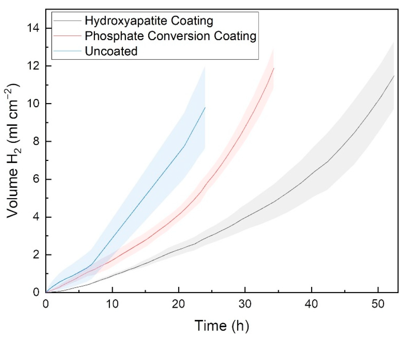
3.5. Corrosion of Coated Porous Scaffolds

As discussed in the introduction, although polarisation tests are known to provide valuable information on corrosion kinetics, previous studies on the corrosion mechanism of porous Mg revealed the limitations of potentiodynamic polarisation test for the determination of corrosion kinetics on porous BJP alloys [34]. This limitation is attributed to the inability of the electric field to penetrate and probe deep into the pore channels, resulting in an underestimation of the actual corrosion rate. As such, the authors deem the corrosion rate determined via hydrogen evolution to be a more accurate representation of corrosion for porous samples compared to polarisation tests. Figure 9 shows the comparison of the hydrogen evolution rate of the uncoated porous Mg-Zn-Zr scaffold with those coated with HA and phosphate conversion coatings. The hydrogen evolution rates of the samples are tabulated in Table 3. The average hydrogen evolution of porous Mg-Zn-Zr scaffold decreases from 0.41 mL cm−2 hr−1 (uncoated) to 0.35 mL cm−2 hr−1 when coated with phosphate conversion coating. The samples that are coated with HA coating demonstrated the most significant decrease in the average hydrogen evolution, reduced to a rate of 0.22 mL cm−2 hr−1. This is a 1.9× and 1.2× decrease in the corrosion rate of the hydroxyapatite (25 °C) and phosphate conversion (0.12 M) coated samples, respectively, over their uncoated counterpart.
It is notable that no direct comparison has been made between the two samples, i.e., coated dense Mg-Zn-Zr samples vs. coated porous Mg-Zn-Zr scaffold. In the authors’ previous work, it was found that the uncoated porous Mg-Zn-Zr scaffold demonstrated a higher corrosion rate than that of a dense Mg-Zn-Zr sample [34,45]. As such, there is no basis for comparison. Instead, the corrosion results are better presented as the improvement in the corrosion performance of the coated samples relative to their uncoated counterpart.

4. Challenges of Coating and Corrosion Testing of Porous Mg-Zn-Zr Scaffolds

Upon further analysis, it is hypothesised that the restricted geometry within the pore channels of the porous Mg-Zn-Zr alloy may have contributed to the discrepancies with the performance of HA and phosphate conversion coatings, in particular, the significant reduction in the effectiveness of the phosphate conversion coating when applied to the porous sample in this work.

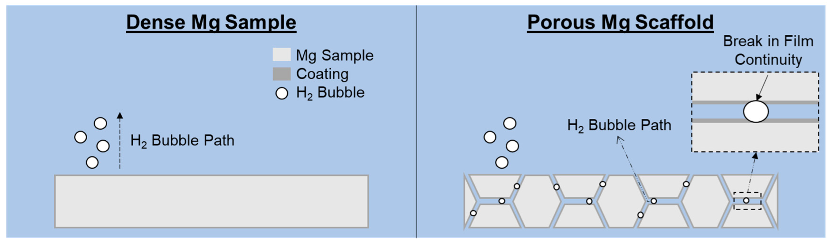
4.1. Influence of H2 Evolution during Coating Process

Equations (1) and (2) show the reaction mechanism for the phosphate conversion coating on an Mg surface [51]. Despite no change in pH being proposed from the reaction, the dissolution of the Mg in the acidic media cannot be avoided. It is known that the dissolution of Mg in acidic media is accompanied by the release of hydrogen gas (Equation (3)) [46]. Figure 10 shows the schematic of the phosphate conversion coating forming process of the dense Mg sample and porous Mg scaffold. Due to restricted geometry within the pore channels of the porous structure, the hydrogen gas formed from the dissolution of Mg may accumulate, isolating the surfaces from the electrolyte and preventing further formation of phosphate coating, which may result in an uneven coating layer. This contrasts with the dense sample where the hydrogen gas evolved can freely detach from the sample surface due to buoyancy force, allowing a more even coating across the sample surface.
Mg OH 2 + 2 H 3 PO 4 Mg H 2 PO 4 2 + 2 H 2 O
MgO + Mg H 2 PO 4 2   ·   2 H 2 O 2 MgHPO 4   ·   3 H 2 O
Mg + 2 H + Mg 2 + + H 2
Conversely, the HA coating was precipitated, filtered, and rinsed before deposition on the Mg-Zn-Zr surfaces. Despite the expectation of hydrogen evolution from the Mg surface during the coating process, due to the availability of the aqueous environment, the lower aggressiveness of the HA solution relative to its phosphate conversion coating counterpart means that less hydrogen evolution can be expected to have occurred during the coating process. Thus, the lowered aggressiveness of the HA deposition solutions may result in a more uniform coating layer and the eventual coating providing better corrosion resistance.
Furthermore, it is known that a compact phosphate conversion coating is required for optimal corrosion protection. Zhou et al. [52] extensively discussed the cracking of chemical conversion coatings on Mg alloys, in particular, the defects caused by the entrapment of H2 bubbles within the coating. From our previous study [45], it is found that there is a significant increase in the cathodic kinetics of the uncoated porous sample over the dense Mg-Zn-Zr sample used in this work due to the presence of MgO. The difference in the hydrogen evolution rate of the porous and dense Mg-Zn-Zr samples may contribute to the increased trapping of hydrogen inside the coating, causing increased hydrogen-induced cracking of the coating and reducing the protection offered, as observed from the discrepancies between the reduction in corrosion offered by the phosphate conversion coating of the porous and dense Mg-Zn-Zr samples in this work.

4.2. Limited Diffusion within the Pore Channel during the Coating and Corrosion Processes

During the coating of porous Mg-Zn-Zr scaffolds, the limited material transport within the porous channels may also result in a high concentration difference between the electrolyte in the bulk solution and that in the pore channels. This contrasts with the coating process of the dense sample where the relatively higher diffusion rate can compensate quickly for variations in localised concentration gradients. This difference may influence the properties of the coating formed. This hypothesis is supported by previously reported findings of variations in coating properties formed under different pH conditions [27,28].
Similarly, the restricted material transport during corrosion, due to limited diffusion within the pore channels, can also result in discrepancies in coating performance. The corrosion performances of coatings are well known to vary with changes in the corroding environment [53,54]. The limited material transport within the pore channels during corrosion can lead to the accumulation of corrosion by-products and local variation of pH, resulting in the alteration of the localised environment affecting the corrosion protection effectiveness of the coating, especially within the channels of the porous Mg-Zn-Zr scaffold.
The combination of possible implications of hydrogen evolution and limited material transport during the coating and corrosion processes means that the quality of applied coatings may perform better or worse in porous Mg structures relative to their dense Mg counterpart. Other than the type of formulation of coating, the extent of performance may vary across structures based on the inherent properties of the pore channels, such as degree of porosity, pore sizes, and tortuosity, which will all affect material transport rates.
In summary, a combination of accumulation of H2 gas during the coating process and the development of different localised conditions within the pore channels compared to the external surface results in an inability to directly translate the corrosion protection performance of coatings from dense solids to porous Mg structures. This means that more focus is needed on the understanding of coating technologies applicable to the corrosion protection of porous Mg structures. The proportionate H2 evolution that occurs from the corrosion of Mg alloys at high rates is known to result in post-implantation mortality [55]. Therefore, improvements in coating knowledge and techniques will allow for better retardation of the corrosion rate of Mg alloys, pushing the boundary for the use of Mg in biomedical applications. In addition, the reduction in the corrosion rate of Mg is also known to positively influence cell adhesion [56], coupled with improved cell proliferation [2] and vascularisation [3] from the porous geometry of the Mg structure. Consequently, the future of Mg as the next-generation biomaterial has never been brighter.

5. Conclusions

In this work, the influence of hydroxyapatite and phosphate conversion coatings on the corrosion performance of conventionally cast, dense Mg-Zn-Zr alloy and binder jet additive manufactured porous Mg-Zn-Zr scaffold was investigated. It was found that the optimum hydroxyapatite and phosphate conversion coatings resulted in a 3x and 4.8x reduction in the corrosion rate of dense Mg-Zn-Zr samples, respectively, and a 1.9x and 1.2x reduction in the corrosion rate of porous Mg-Zn-Zr scaffold, respectively. The discrepancies between the corrosion performance of hydroxyapatite and phosphate conversion coating, when applied to dense and porous Mg-Zn-Zr samples, can be attributed to both the microstructure and the geometry’s influence on the binder jet additive manufactured porous Mg-Zn-Zr scaffold, which not only increases the rate of hydrogen evolution but also reduces the ability of the hydrogen gas generated within the pore channels to escape to the sample surface. This restricts the effectiveness of the coating application for porous Mg scaffolds. The limited diffusion within the pore channels can also result in differing localized corrosion environments, causing discrepancies between the localised corrosion environment within the pore channels and those at the bulk electrolyte.

Author Contributions

Conceptualization, K.X.K., M.S., Z.H. and D.J.B.; methodology, K.X.K.; validation, K.X.K., M.S. and Z.H.; formal analysis, K.X.K., M.S. and Z.H.; investigation, Z.H.; resources, S.X.Z.; data curation, K.X.K., M.S. and Z.H.; writing—original draft preparation, K.X.K. and Z.H.; writing—review and editing, M.S. and D.J.B.; supervision, S.X.Z.; project administration, H.L.S., M.L.S.N. and D.J.B.; funding acquisition, M.L.S.N. and D.J.B. All authors have read and agreed to the published version of the manuscript.

Funding

This research was funded by the first Singapore-Germany academic-industry (2+2) international collaboration grant (Grant no. A1890b0050) and Agency for Science, Technology and Research (A*STAR), under the RIE2020 Advanced Manufacturing and Engineering (AME) Programmatic Grant (Grant no. A18B1b0061).

Data Availability Statement

The data presented in this study are available on request from the corresponding authors. The data are not publicly available due to ongoing studies.

Conflicts of Interest

The authors declare no conflict of interest.

References

  1. Malda, J.; Woodfield, T.B.F.; Van Der Vloodt, F.; Wilson, C.; Martens, D.E.; Tramper, J.; Van Blitterswijk, C.A.; Riesle, J. The effect of PEGT/PBT scaffold architecture on the composition of tissue engineered cartilage. Biomaterials 2005, 26, 63–72. [Google Scholar] [CrossRef] [PubMed]
  2. Samourides, A.; Browning, L.; Hearnden, V.; Chen, B. The effect of porous structure on the cell proliferation, tissue ingrowth and angiogenic properties of poly(glycerol sebacate urethane) scaffolds. Mater. Sci. Eng. C 2020, 108, 110384. [Google Scholar] [CrossRef] [PubMed]
  3. Cheng, A.; Schwartz, Z.; Kahn, A.; Li, X.; Shao, Z.; Sun, M.; Ao, Y.; Boyan, B.D.; Chen, H. Advances in Porous Scaffold Design for Bone and Cartilage Tissue Engineering and Regeneration. Tissue Eng. Part B Rev. 2019, 25, 14–29. [Google Scholar] [CrossRef] [PubMed]
  4. Bairagi, D.; Mandal, S. A comprehensive review on biocompatible Mg-based alloys as temporary orthopaedic implants: Current status, challenges, and future prospects. J. Magn. Alloys 2022, 10, 627–669. [Google Scholar] [CrossRef]
  5. Ding, P.; Liu, Y.; He, X.; Liu, D.; Chen, M. In vitro and in vivo biocompatibility of Mg–Zn–Ca alloy operative clip. Bioact. Mater. 2019, 4, 236–244. [Google Scholar] [CrossRef]
  6. Hiromoto, S.; Inoue, M.; Taguchi, T.; Yamane, M.; Ohtsu, N. In vitro and in vivo biocompatibility and corrosion behaviour of a bioabsorbable magnesium alloy coated with octacalcium phosphate and hydroxyapatite. Acta Biomater. 2015, 11, 520–530. [Google Scholar] [CrossRef]
  7. Benn, F.; Kröger, N.; Zinser, M.; van Gaalen, K.; Vaughan, T.J.; Yan, M.; Smeets, R.; Bibiza, E.; Malinov, S.; Buchanan, F.; et al. Influence of surface condition on the degradation behaviour and biocompatibility of additively manufactured WE43. Mater. Sci. Eng. C 2021, 124, 112016. [Google Scholar] [CrossRef]
  8. Sezer, N.; Evis, Z.; Koç, M. Additive manufacturing of biodegradable magnesium implants and scaffolds: Review of the recent advances and research trends. J. Magn. Alloys 2021, 9, 392–415. [Google Scholar] [CrossRef]
  9. Sharma, P.; Pandey, P.M. Corrosion rate modelling of biodegradable porous iron scaffold considering the effect of porosity and pore morphology. Mater. Sci. Eng. C 2019, 103, 109776. [Google Scholar] [CrossRef]
  10. Md Saad, A.P.; Jasmawati, N.; Harun, M.N.; Abdul Kadir, M.R.; Nur, H.; Hermawan, H.; Syahrom, A. Dynamic degradation of porous magnesium under a simulated environment of human cancellous bone. Corros. Sci. 2016, 112, 495–506. [Google Scholar] [CrossRef]
  11. Chen, X.-B.; Li, C.; Xu, D. Biodegradation of Mg-14Li alloy in simulated body fluid: A proof-of-concept study. Bioact. Mater. 2018, 3, 110–117. [Google Scholar] [CrossRef] [PubMed]
  12. Xu, W.; Birbilis, N.; Sha, G.; Wang, Y.; Daniels, J.E.; Xiao, Y.; Ferry, M. A high-specific-strength and corrosion-resistant magnesium alloy. Nat. Mater. 2015, 14, 1229–1235. [Google Scholar] [CrossRef] [PubMed]
  13. Rahman, M.; Li, Y.; Wen, C. HA coating on Mg alloys for biomedical applications: A review. J. Magn. Alloys 2020, 8, 929–943. [Google Scholar] [CrossRef]
  14. Johari, N.A.; Alias, J.; Zanurin, A.; Mohamed, N.S.; Alang, N.A.; Zain, M.Z.M. Anti-corrosive coatings of magnesium: A review. Mater. Today Proc. 2022, 48, 1842–1848. [Google Scholar] [CrossRef]
  15. Hornberger, H.; Virtanen, S.; Boccaccini, A.R. Biomedical coatings on magnesium alloys—A review. Acta Biomater. 2012, 8, 2442–2455. [Google Scholar] [CrossRef]
  16. Tokunaga, T.; Ohno, M.; Matsuura, K. Coatings on Mg alloys and their mechanical properties: A review. J. Mater. Sci. Technol. 2018, 34, 1119–1126. [Google Scholar] [CrossRef]
  17. Zeng, R.; Lan, Z.; Kong, L.; Huang, Y.; Cui, H. Characterization of calcium-modified zinc phosphate conversion coatings and their influences on corrosion resistance of AZ31 alloy. Surf. Coat Technol. 2011, 205, 3347–3355. [Google Scholar] [CrossRef] [Green Version]
  18. Arrabal, R.; Matykina, E.; Viejo, F.; Skeldon, P.; Thompson, G.E. Corrosion resistance of WE43 and AZ91D magnesium alloys with phosphate PEO coatings. Corros. Sci. 2008, 50, 1744–1752. [Google Scholar] [CrossRef]
  19. Van Phuong, N.; Moon, S. Comparative corrosion study of zinc phosphate and magnesium phosphate conversion coatings on AZ31 Mg alloy. Mater. Lett. 2014, 122, 341–344. [Google Scholar] [CrossRef]
  20. Chen, X.B.; Birbilis, N.; Abbott, T.B. A simple route towards a hydroxyapatite-Mg(OH)2 conversion coating for magnesium. Corros. Sci. 2011, 53, 2263–2268. [Google Scholar] [CrossRef]
  21. Pezzato, L.; Brunelli, K.; Diodati, S.; Pigato, M.; Bonesso, M.; Dabalà, M. Microstructural and corrosion properties of hydroxyapatite containing peo coating produced on az31 mg alloy. Materials 2021, 14, 1531. [Google Scholar] [CrossRef] [PubMed]
  22. Tsuruga, E.; Takita, H.; Itoh, H.; Wakisaka, Y.; Kuboki, Y. Pore size of porous hydroxyapatite as the cell-substratum controls BMP-induced osteogenesis. J. Biochem. 1997, 121, 317–324. [Google Scholar] [CrossRef] [PubMed] [Green Version]
  23. Hasniyati, M.; Zuhailawati, H.; Sivakumar, R.; Dhindaw, B.K.; Noor, S.N.F.M. Cold spray deposition of hydroxyapatite powder onto magnesium substrates for biomaterial applications. Surf. Eng. 2015, 31, 867–874. [Google Scholar] [CrossRef]
  24. Noorakma, A.C.W.; Zuhailawati, H.; Aishvarya, V.; Dhindaw, B.K. Hydroxyapatite-Coated Magnesium-Based Biodegradable Alloy: Cold Spray Deposition and Simulated Body Fluid Studies. J. Mater. Eng. Perform. 2013, 22, 2997–3004. [Google Scholar] [CrossRef]
  25. Narayanan, T.S.N.S.; Lee, M.H. A simple strategy to modify the porous structure of plasma electrolytic oxidation coatings on magnesium. RSC Adv. 2016, 6, 16100–16114. [Google Scholar] [CrossRef]
  26. Dong, J.; Tümer, N.; Putra, N.E.; Zhu, J.; Li, Y.; Leeflang, M.A.; Taheri, P.; Fratila-Apachitei, L.E.; Mol, J.M.C.; Zadpoor, A.A.; et al. Extrusion-based 3D printed magnesium scaffolds with multifunctional MgF2 and MgF2–CaP coatings. Biomater. Sci. 2021, 9, 7159–7182. [Google Scholar] [CrossRef]
  27. Jayaraj, J.; Amruth Raj, S.; Srinivasan, A.; Ananthakumar, S.; Pillai, U.T.S.; Dhaipule, N.G.K.; Mudali, U.K. Composite magnesium phosphate coatings for improved corrosion resistance of magnesium AZ31 alloy. Corros. Sci. 2016, 113, 104–115. [Google Scholar] [CrossRef]
  28. Zai, W.; Su, Y.; Man, H.C.; Lian, J.; Li, G. Effect of pH value and preparation temperature on the formation of magnesium phosphate conversion coatings on AZ31 magnesium alloy. Appl. Surf. Sci. 2019, 492, 314–327. [Google Scholar] [CrossRef]
  29. Shirokova, A.G.; Bogdanova, E.A.; Skachkov, V.M.; Pasechnik, L.A.; Borisov, S.V.; Sabirzyanov, N.A. Bioactive coatings of porous materials: Fabrication and properties. J. Surf. Investig. 2017, 11, 107–113. [Google Scholar] [CrossRef]
  30. Ghasemi, A.; Kamrani, S.; Hübler, D.; Fleck, C. Corrosion behavior of porous magnesium coated by plasma electrolytic oxidation in simulated body fluid. Mater. Corros. 2019, 70, 1561–1569. [Google Scholar] [CrossRef]
  31. Daavari, M.; Atapour, M.; Mohedano, M.; Sánchez, H.M.; Rodríguez-Hernández, J.; Matykina, E.; Arrabal, R.; Taherizadeh, A. Quasi-in vivo corrosion behavior of AZ31B Mg alloy with hybrid MWCNTs-PEO/PCL based coatings. J. Magn. Alloys 2021, 10, 3217–3233. [Google Scholar] [CrossRef]
  32. Castro, Y.; Durán, A. Control of degradation rate of Mg alloys using silica sol–gel coatings for biodegradable implant materials. J. Solgel Sci. Technol. 2019, 90, 198–208. [Google Scholar] [CrossRef]
  33. Kirkland, N.; Birbilis, N.; Staiger, M. Assessing the corrosion of biodegradable magnesium implants: A critical review of current methodologies and their limitations. Acta Biomater. 2012, 61, 65–69. [Google Scholar] [CrossRef] [PubMed]
  34. Kuah, K.X.; Blackwood, D.J.; Ong, W.K.; Salehi, M.; Seet, H.L.; Nai, M.L.S.; Wijesinghe, S. Analysis of the corrosion performance of binder jet additive manufactured magnesium alloys for biomedical applications. J. Magn. Alloys 2022, 10, 1296–1310. [Google Scholar] [CrossRef]
  35. Kleger, N.; Cihova, M.; Masania, K.; Studart, A.R.; Löffler, J.F. 3D Printing of Salt as a Template for Magnesium with Structured Porosity. Adv. Mater. 2019, 31, 1903783. [Google Scholar] [CrossRef]
  36. Kapłon, H.; Blawert, C.; Chęcmanowski, J.; Naplocha, K. Development of open-porosity magnesium foam produced by investment casting. J. Magn. Alloys 2022, 10, 1941–1956. [Google Scholar] [CrossRef]
  37. Kang, M.H.; Lee, H.; Jang, T.S.; Seong, Y.J.; Kim, H.E.; Koh, Y.H.; Song, J.; do Jung, H. Biomimetic porous Mg with tunable mechanical properties and biodegradation rates for bone regeneration. Acta Biomater. 2019, 84, 453–467. [Google Scholar] [CrossRef]
  38. Kucharczyk, A.; Naplocha, K.; Kaczmar, J.W.; Dieringa, H.; Kainer, K.U. Current Status and Recent Developments in Porous Magnesium Fabrication. Adv. Eng. Mater. 2018, 20, 1700562. [Google Scholar] [CrossRef]
  39. Salehi, M.; Maleksaeedi, S.; Nai, S.M.L.; Meenashisundaram, G.K.; Goh, M.H.; Gupta, M. A paradigm shift towards compositionally zero-sum binderless 3D printing of magnesium alloys via capillary-mediated bridging. Acta Mater. 2019, 165, 294–306. [Google Scholar] [CrossRef]
  40. Salehi, M.; Maleksaeedi, S.; bin Sapari, M.A.; Nai, M.L.S.; Meenashisundaram, G.K.; Gupta, M. Additive manufacturing of magnesium–zinc–zirconium (ZK) alloys via capillary-mediated binderless three-dimensional printing. Mater. Des. 2019, 169, 107683. [Google Scholar] [CrossRef]
  41. Salehi, M.; Seet, H.L.; Gupta, M.; Farnoush, H.; Maleksaeedi, S.; Nai, M.L.S. Rapid densification of additive manufactured magnesium alloys via microwave sintering. Addit. Manuf. 2021, 37, 101655. [Google Scholar] [CrossRef]
  42. Salehi, M.; Maleksaeedi, S.; Nai, M.L.S.; Gupta, M. Towards additive manufacturing of magnesium alloys through integration of binderless 3D printing and rapid microwave sintering. Addit. Manuf. 2019, 29, 100790. [Google Scholar] [CrossRef]
  43. Song, G.; Atrens, A.; StJohn, D. An Hydrogen Evolution Method for the Estimation of the Corrosion Rate of Magnesium Alloys. In Magnesium Technology 2001; John Wiley & Sons, Inc.: Hoboken, NJ, USA, 2013; pp. 254–262. [Google Scholar] [CrossRef]
  44. Salehi, M.; Maleksaeedi, S.; Farnoush, H.; Nai, M.L.S.; Meenashisundaram, G.K.; Gupta, M. An investigation into interaction between magnesium powder and Ar gas: Implications for selective laser melting of magnesium. Powder Technol. 2018, 333, 252–261. [Google Scholar] [CrossRef]
  45. Kuah, K.X.; Salehi, M.; Ong, W.K.; Seet, H.L.; Nai, M.L.S.; Wijesinghe, S.; Blackwood, D.J. Insights into the influence of oxide inclusions on corrosion performance of additive manufactured magnesium alloys. NPJ Mater. Degrad. 2022, 6, 36. [Google Scholar] [CrossRef]
  46. Gusieva, K.; Davies, C.H.J.; Scully, J.R.; Birbilis, N. Corrosion of magnesium alloys: The role of alloying. Int. Mater. Rev. 2015, 60, 169–194. [Google Scholar] [CrossRef]
  47. Gandel, D.S.; Easton, M.A.; Gibson, M.A.; Abbott, T.; Birbilis, N. The influence of zirconium additions on the corrosion of magnesium. Corros. Sci. 2014, 81, 27–35. [Google Scholar] [CrossRef]
  48. Clark, J.B. Transmission electron microscopy study of age hardening in a Mg-5 wt.% Zn alloy. Acta Metall. 1965, 13, 1281–1289. [Google Scholar] [CrossRef]
  49. Chun, J.S.; Byrne, J.G. Precipitate strengthening mechanisms in magnesium zinc alloy single crystals. J. Mater. Sci. 1969, 4, 861–872. [Google Scholar] [CrossRef]
  50. Zhang, X.; Böhm, S.; Bosch, A.J.; van Westing, E.P.M.; de Wit, J.H.W. Influence of drying temperature on the corrosion performance of chromate coatings on galvanized steel. Mater. Corros. 2004, 55, 501–510. [Google Scholar] [CrossRef]
  51. Fouladi, M.; Amadeh, A. Comparative study between novel magnesium phosphate and traditional zinc phosphate coatings. Mater. Lett. 2013, 98, 1–4. [Google Scholar] [CrossRef]
  52. Zhou, P.; Yu, B.; Hou, Y.; Duan, G.; Yang, L.; Zhang, B.; Zhang, T.; Wang, F. Revisiting the cracking of chemical conversion coating on magnesium alloys. Corros. Sci. 2021, 178, 109069. [Google Scholar] [CrossRef]
  53. Hua, T.S.; Song, R.G.; Zong, Y.; Cai, S.W.; Wang, C. Effect of solution pH on stress corrosion and electrochemical behaviour of aluminum alloy with micro-arc oxidation coating. Mater. Res. Express. 2019, 6, 096441. [Google Scholar] [CrossRef]
  54. Sadeghi, S.; Ebrahimifar, H. Effect of Electrolyte pH on Microstructure, Corrosion Behavior, and Mechanical Behavior of Ni-P-W-TiO2 Electroplated Coatings. J. Mater. Eng. Perform. 2021, 30, 2409–2421. [Google Scholar] [CrossRef]
  55. Noviana, D.; Paramitha, D.; Ulum, M.F.; Hermawan, H. The effect of hydrogen gas evolution of magnesium implant on the postimplantation mortality of rats. J. Orthop. Transl. 2016, 5, 9–15. [Google Scholar] [CrossRef] [Green Version]
  56. Wagener, V.; Schilling, A.; Mainka, A.; Hennig, D.; Gerum, R.; Kelch, M.L.; Keim, S.; Fabry, B.; Virtanen, S. Cell Adhesion on Surface-Functionalized Magnesium. ACS Appl. Mater. Interfaces 2016, 8, 11998–12006. [Google Scholar] [CrossRef]
Figure 1. Schematic of the hydrogen evolution setup for Mg samples, maintained at 37 °C with a water bath.
Crystals 12 01850 g001
Figure 2. SEM micrographs and EDX elemental mappings for the samples, (a) dense and (b) porous Mg-Zn-Zr scaffold.
Crystals 12 01850 g002
Figure 3. XRD characterisation of dense Mg-Zn-Zr and porous Mg-Zn-Zr scaffold.
Crystals 12 01850 g003
Figure 4. X-Ray Computed Tomography. (a) 2-dimensional (2d) and (b) 3-dimensional (3d) recreation of the porous Mg-Zn-Zr scaffold manufactured via binder jet printing. The red arrows indicate the building direction (stacking direction of the powder).
Crystals 12 01850 g004
Figure 5. SEM images of the dense Mg-Zn-Zr sample after (a) hydroxyapatite coated dried at 25 °C, and phosphate conversion coated with initial concentration of (b) 0.12 M, (c) 0.16 M, and (d) 0.24 M phosphoric acid.
Crystals 12 01850 g005
Figure 6. Potentiodynamic polarisation of dense Mg-Zn-Zr samples coated with (a) hydroxyapatite at different drying temperatures and (b) phosphoric conversion coating with different initial concentrations of phosphoric acid. The polarisations curved were obtained after 30 min immersion in 0.1 M NaCl at a scan rate of 1 mV s−1.
Crystals 12 01850 g006
Figure 7. SEM and EDX images of the porous Mg-Zn-Zr scaffold’s fracture surface coated with hydroxyapatite.
Crystals 12 01850 g007
Figure 8. SEM and EDX images of the porous Mg-Zn-Zr scaffold’s fracture surface coated with phosphate conversion coating.
Crystals 12 01850 g008
Figure 9. Hydrogen evolution comparison between uncoated, hydroxyapatite-coated, and phosphoric conversion coated porous Mg-Zn-Zr scaffolds. The shaded regions represent the standard deviation of the respective hydrogen evolution collection data.
Crystals 12 01850 g009
Figure 10. Schematic of the phosphate conversion coating forming process of both dense Mg sample and porous Mg scaffold. As the hydrogen gas that evolves within the pore channels is unable to escape freely, its accumulation leads to a break in film continuity during the film formation process.
Crystals 12 01850 g010
Table 1. Chemical composition of dense and porous Mg-Zn-Zr samples as determined from ICP-OES. The oxygen content of the porous sample was determined from inert gas fusion infrared absorbance. ICP was also used to analyse a range of additional metallic elements including Al, As, B, Be, Ca, Cd, Cr, Co, Cu, Fe, Hf, Mo, Mn, Nb, Ni, P, Pb, Re, Sb, Si, Sn, Ta, Ti, Y, V and W, none of which were found to exceed 0.01 wt.% in any of the alloys.
SampleZn (wt.%)Zr (wt.%)O (wt.%)Mg (wt.%)
As cased dense5.490.73-Bal.
BJP porous5.160.180.12Bal.
Table 2. Corrosion current of uncoated 2-dimensional (dense) Mg-Zn-Zr, HA-coated dense Mg-Zn-Zr, and phosphate-coated dense Mg-Zn-Zr alloy, obtained from Tafel extrapolation of respective potentiodynamic polarisation curve in 0.1 M NaCl.
SampleCorrosion Current Density
(×10−6 A cm−2)
Uncoated dense Mg-Zn-Zr15.0
Hydroxyapatite dried at 25 °C5.0
Hydroxyapatite dried at 40 °C52.6
Hydroxyapatite dried at 55 °C6.2
Hydroxyapatite dried at 100 °C22.0
0.12 M H3PO43.1
0.16 M H3PO44.7
0.24 M H3PO45.9
Table 3. Tabulated average hydrogen evolution rate of uncoated and coated porous Mg-Zn-Zr samples with hydroxyapatite and phosphate conversion coating in PBS maintained at 37 °C.
SampleAverage Hydrogen Evolution Rate (mL cm−2 hr−1)
Uncoated porous0.41 ± 0.09
Phosphate Conversion Coating0.35 ± 0.03
Hydroxyapatite Coating0.22 ± 0.03
Publisher’s Note: MDPI stays neutral with regard to jurisdictional claims in published maps and institutional affiliations.

