1. Introduction
Flat panel displays currently suffer from the contradiction between information capacity, portability and power consumption, so people are actively exploring next-generation display technologies. AR near-eye display devices are considered the next generation of information display terminals due to their wearability, translucency, and ability to achieve huge screen displays with low power consumption. The wavelength and angular selectivity of the liquid crystal optical elements (LCOEs) allow the see-through view of the real scene to be transmitted to the eye unaltered, thereby enabling an optical see-through AR configuration. In the meantime, LCOEs can be made on very thin substrates, allowing the display system to have a favorable profile and be lightweight for a better wearing experience for the user.
Research on LCOEs with photoalignment techniques began in the early 1980s [
1]. Since then, recording materials and methods have been steadily improved. Currently, Pancharatnam-Berry (PB) phase gratings [
2,
3] or lens [
4,
5,
6,
7], cholesteric liquid crystal (CLC) reflectors [
8], and polarization volume gratings (PVG) [
9,
10,
11,
12,
13,
14] or lens (PVL) [
15,
16,
17] are the main LCOEs used for near-eye displays. In the current near-eye display, waveguide display solutions are one of the industry’s focuses. As PVG overcomes the problems of low efficiency of surface relief grating (SRG) and narrow response bandwidth of volume holographic grating (VHG), PVG-based waveguide displays have been widely studied and demonstrated in recent years. Weng et al. proposed a dual-layer PVG-based waveguide solution to achieve a full-color AR display with a 35° diagonal field of view (FOV) [
18]. The dual-layer structure is specifically a blue composite green sharing one layer of the waveguide, with red propagating independently in another layer of the waveguide. Cui et al. demonstrated a PVG-based waveguide display system with a 35° diagonal FOV using an “L” shaped two-dimensional exit pupil expansion structure [
19]. Then, Gu et al. superimposed PVGs with different polarization responses as coupling elements and extended the angular response bandwidth by stacking PVGs to improve the efficiency and FOV of the waveguide system [
20]. However, the limits of the FOV that can be achieved with PVG-based waveguide displays have not been explored, especially in the case of full-color waveguide displays.
To enable a better understanding of the design challenges of PVG-based waveguides, this paper presents different schemes for realizing full-color diffractive waveguide display, including single-layer waveguides, dual-layer waveguides, and three-layer waveguides, providing an analysis of the FOV that such schemes can support. And in combination with bandwidth compounding [
20], we simulate and experimentally demonstrate a dual-layer PVG-based waveguide RGB display scheme that achieves the same RGB FOV as the three-layer waveguide while reducing the size of the three-layer waveguide.
2. Device Design and Simulation
PVG has a complex three-dimensional helical structure, which tends to have the lowest free energy state [
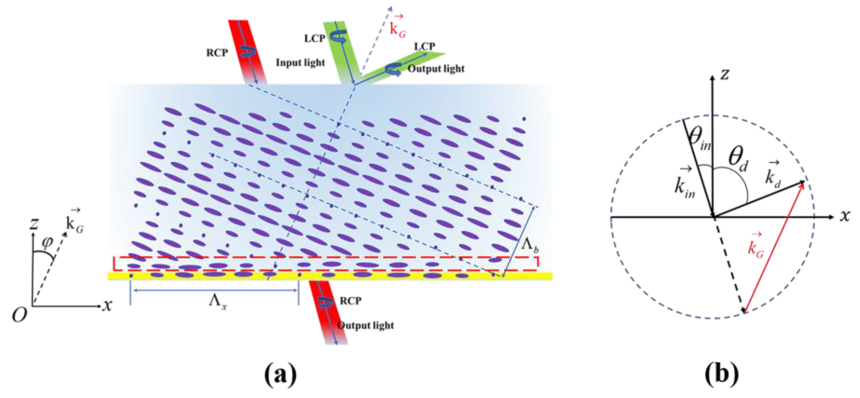
21]. As sketched in
Figure 1a, the azo molecular compound at the bottom acts as an optical orientation layer, which shows a sinusoidal pattern along the
x-axis. Meanwhile, there exists a transition region in which the liquid crystal molecules change from planar to three-dimensional helical orientation [
22], and there exists a grating inclination angle
, which satisfies the Bragg equation:
where
is the average refractive index of the PVG material,
p is the length of the liquid crystal molecule rotated by 360°,
is the Bragg angle,
is the PVG Bragg wavelength,
is the PVG Bragg period and
is the PVG lateral period. The self-assembled helical structure has sensitive polarization response characteristics. For the PVG with a left-handed helical structure, when the incident light is left-handed circularly polarized (LCP), strong primary diffraction will occur, while when the incident light is right-handed circularly polarized (RCP), the light will pass directly through the grating without diffraction.
To satisfy the Bragg condition,
Figure 1b shows that the k-vector of the incident light, diffracted light and the grating vector should form a triangular relationship:
. When the incident light is coupled into the PVG waveguide from air, and the total internal reflection (TIR) occurs, the diffraction angle
(in waveguide media with refractive index
) and the incident angle
(in air) should satisfy:
where
is the wavelength of the incident light in a vacuum. The diffraction angle is limited by the refractive index of the waveguide and must be greater than the TIR:
The corresponding incident angle is
Equation (4) shows that one boundary of the FOV is not affected by the refractive index of the waveguide but is closely related to the ratio of the incident wavelength to the PVG lateral period. Assuming that the maximum propagation angle in the waveguide is
, the corresponding incident angle is
Therefore, the FOV can be calculated as
It is important to note that the FOV mentioned here refers to the horizontal FOV in air, as well as the FOV not specifically described below. From the above equation, it seems that the FOV is related to
, and the FOV increases as
increases. However, for VHG or PVG, the incident light is diffracted inside the grating, so the diffraction angle inside the grating cannot exceed 90 degrees:
This requires a matching refractive index between the grating and the waveguide medium. Otherwise, the upper limit of the propagation angle will be greatly limited. When the refractive index of the waveguide medium is matched with the refractive index of the grating material,
, is determined by the allowable collimator aperture W and the thickness of the waveguide
t:
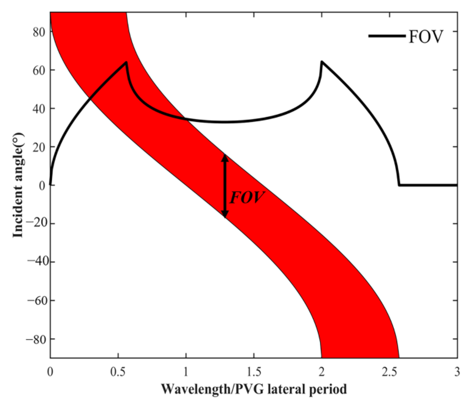
In the actual design application, we first choose the
matching with
. The
W and
t used in this paper are set to 18 mm and 0.7 mm, respectively, and the relationship between FOV and
, in this case, is shown in
Figure 2. The FOV is in an approximately symmetric trend with the
. When
approaches 0.5 times or 1.78 times the value of
, the FOV tends to the maximum. And since the larger the
is in the PVG preparation process, the better the arrangement of PVG liquid crystal molecules will be, so we prefer a larger
when designing a large FOV.
The simplest way to achieve a full-color waveguide display is to use stacked waveguides, each designed for a single color (R, G, or B), and by adjusting the diffraction angle of the grating, the maximum RGB FOV can be obtained. Independent three-layer waveguides are used to transmit R, G and B band beams, respectively. Since the beam propagation of the three bands is independent, the diffraction angles of the corresponding three coupled beams can be designed independently as needed without worrying about crosstalk. The architecture is currently used in many SRG waveguides, such as HoloLens 1 and Magic Leap One. When designing a PVG-based full-color waveguide, as shown in
Figure 2, it is sufficient to obtain a corresponding
according to the desired FOV, and thus the suitable
can be obtained for different wavelengths of incident light. The RGB FOV of the three-layer color waveguide structure is comparable to the monochromatic case. However, the main drawback of this structure is that it leads to an inevitable increase in the size and weight of the system.
PVG composite technology allows for a single-layer color waveguide system structure, thus minimizing the thickness and weight of the waveguide. A single-layer waveguide is a composite of red PVG, green PVG, and blue PVG in some form, and the coupled beam is transmitted within the same waveguide. This structure keeps the thickness and weight within the desired range because there is only a single layer of waveguide medium. Nevertheless, the single-layer waveguide structure has strict requirements for coupling composite gratings. Specifically, the R, G, and B grating components of the composite grating need to have an equal lateral period so that R, G and B grating components have the same dispersion curve, otherwise severe crosstalk will occur between the different grating components, leading to dispersion and ghosting in the final image.
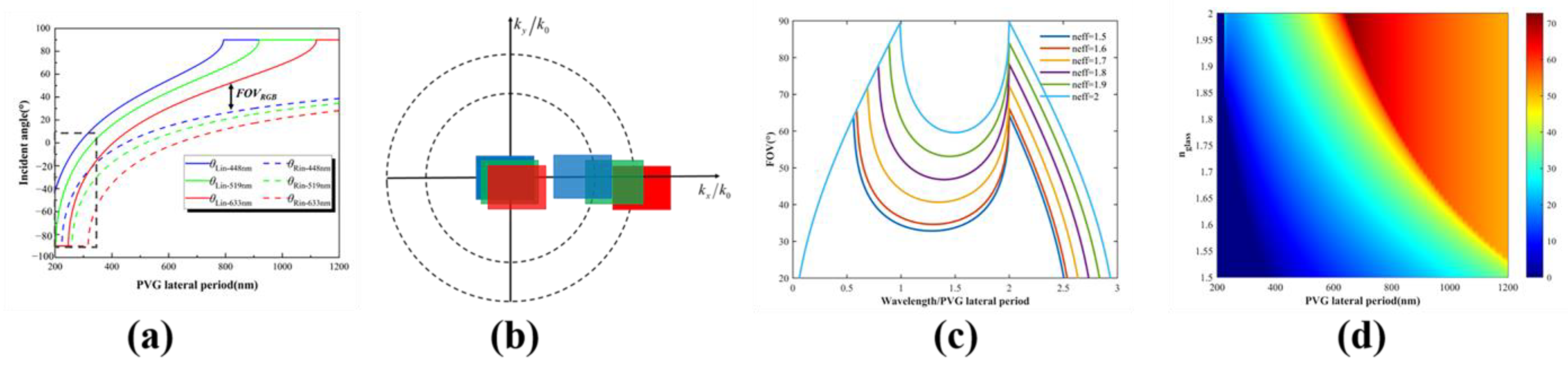
Figure 3a plots the curves for different values of
corresponding to different incident angle ranges at R (633 nm), G (519 nm), and B (448 nm) bands in the single-layer RGB waveguide structure. When
is very small, R and B cannot be transmitted in the waveguide at the same time (black dashed box), which confirms the wisdom of our previous choice of large
. In the case of large
, it is difficult to couple all RGB light into the waveguide over a large angular range if
is fixed for R, G, and B (
Figure 3b). Compared to the three-layer waveguide solution, RGB FOV will obviously have a significant loss.
Since the
of the PVG material we prepare is around 1.57,
is also chosen to be 1.57, and the diffraction angle will be distributed in a limited range of waveguide propagation angles according to the dispersion curve, thus limiting FOV. If we want to achieve a larger FOV, we need to increase
and the corresponding
. As shown in
Figure 3c, when the refractive index reaches 2, the FOV can reach about 90°. At the same time, the tilt angle between the light engine and the waveguide sheet can be smaller if a larger FOV is desired. Similarly, the RGB FOV of the single-layer waveguide becomes larger as
and
increase. As shown in
Figure 3d, the RGB FOV of single-layer waveguides can also achieve up to nearly 70°. Relevant materials for high-refractive-index waveguide media are available, so it is necessary to find suitable high-refractive-index PVG materials in the future.
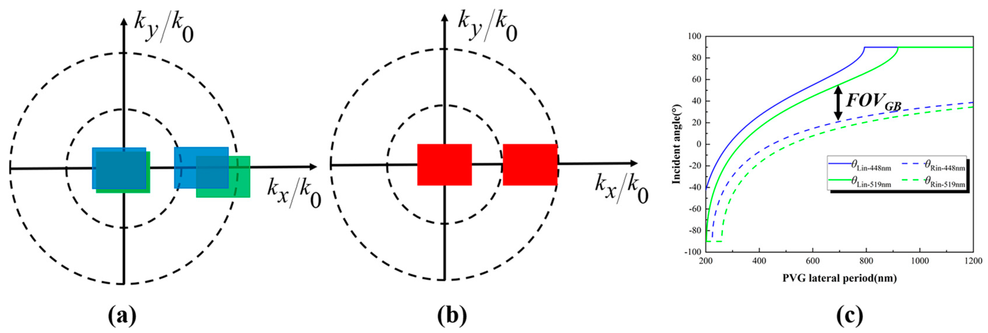
A dual-layer PVG RGB waveguide proposed by Weng et al. [
18] reduces the weight and volume of the three-layer waveguide while also avoiding the small FOV of the single-layer waveguide [
18]. Their scheme is to share one layer of waveguide for B and G and propagate R separately, as is shown in
Figure 4a,b. When blue and green are in the same layer of the waveguide, and when we ensure that one of the color components propagates with full FOV, there inevitably exists a portion of the FOV of the other color component that cannot satisfy the propagation conditions of the waveguide.
Figure 4c shows the incident angles satisfying the propagation conditions of G (519 nm) and B (448 nm) at different
values. In this instance, the FOV can be expressed as:
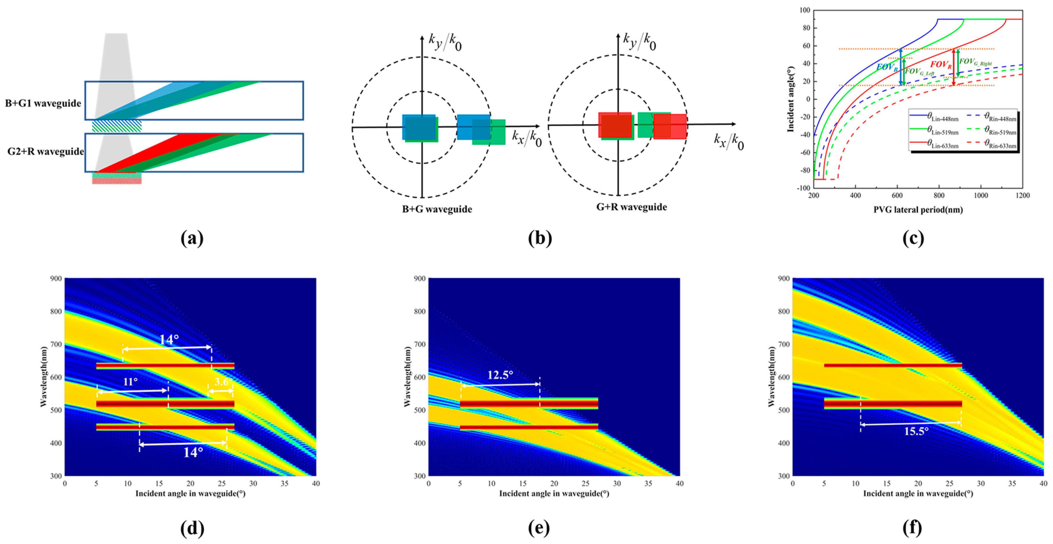
Another PVG-based dual-layer RGB waveguide is proposed in this paper, as shown in
Figure 5a. This structure places B and G1 in the same waveguide and G2 and R in the same waveguide. As can be seen in
Figure 5b, G1 is responsible for the green left part of the FOV and G2 is responsible for the green right FOV. G1 and G2 have partially overlapping FOVs in some cases (
Figure 5c). To prevent the problem that the light diffracted by G1 is diffracted again by G2 during the propagation to the human eye in the out-coupling grating region, we can use G1 and G2 with different polarization responses in the out-coupling region. This dual-layer RGB waveguide can effectively reduce the size and weight of conventional three-layer RGB waveguides and maintain the same FOV as three-layer RGB waveguides.
In order to match the light engine used in the experimental section, we need to select a suitable PVG lateral period. The diagonal field of view of the light engine used in the experimental section is 45° (resolution 4:3), so the lateral field of view needs to be guaranteed to be about 36°. According to
Figure 2, we can calculate that the R (633 nm) PVG lateral period needs to be set near 705 nm, and the B (448 nm) PVG lateral period needs to be set near 501 nm. In the PVG preparation process, the lateral period is determined by the exposure angle and based on the current accuracy of our exposure rotary table of only 1°, the final R (633 nm) PVG lateral period is set to 739.44 nm, and the Bragg angle is 16.62°, and the B (448 nm) PVG lateral period is set to 521.25 nm, and the Bragg angle is 16.62°. The FOV of this light engine ranges from 8.6° to 44.6° (in air). For the efficiency of the PVGs in
Figure 5d, the red band FOV supported is only 14° (22.3° in air), and the blue band FOV supported is only 14° (22.3° in air). And the FOV of the green band is divided into 8.6°–26.5° (in air) and 39°–44.6° (in air) under the circumstances.
We need to fill in the missing part of the FOV with laminated composite PVGs [
20]. We superimposed three layers of PVG in the R+G2 waveguide and two layers of PVG in the B+G1 waveguide. The parameters for the design of each layer of PVG are shown in
Table 1. As shown in
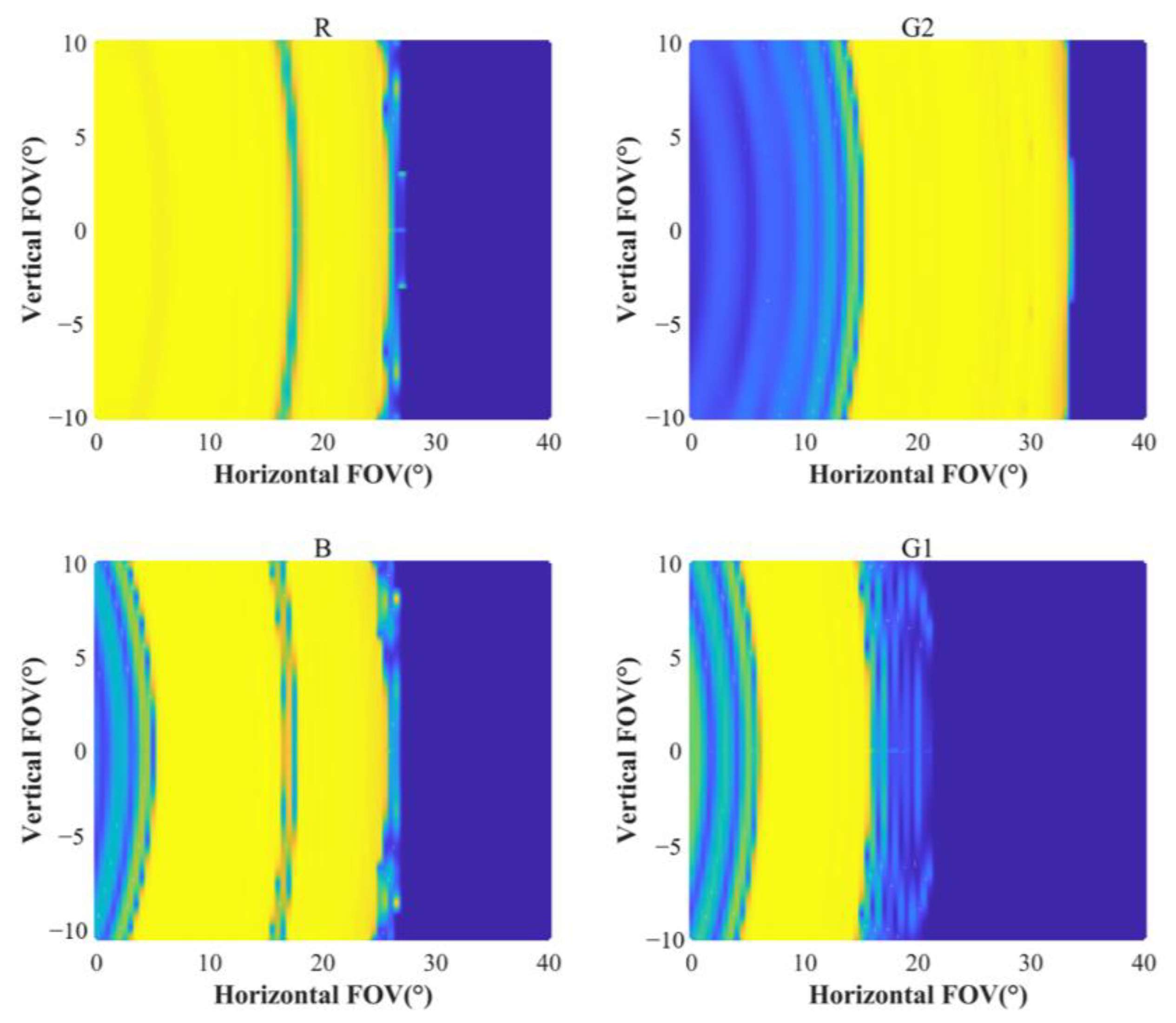
Figure 5e,f, the FOV of the red band of the light engine will be fully displayed in the R+G2 waveguide, the blue band will be fully displayed in the B+G1 waveguide, and the green band will be fully displayed in the B+G1 waveguide (8.6°–29° in air) and R+G2 waveguide (17.5°–44.6° in air), respectively. We also simulated the efficiency distribution of the horizontal FOV and vertical FOV for this design parameter (
Figure 6). The horizontal coordinates represent the range of incident light angles along the waveguide propagation direction, and the vertical coordinates represent the range of incident light angles perpendicular to the waveguide propagation direction. We designed the incident light wavelengths as R (633 nm), G (519 nm), and B (448 nm), respectively. Red and blue propagate with an entire FOV in their respective waveguides, while the green FOV is split into two parts to propagate. Both horizontal and vertical field-of-view angles are satisfied with this structure.
3. Device Fabrication and Results
The experimental procedure was similar to that described in [
20] except for the different chiral agent concentrations (mass ratio of chiral agent to photocurable monomer) and exposure angles. The azo-dye brilliant yellow (0.5 wt.% BY in DMF) is coated onto the cleaned glass substrate to form a photo-alignment (PA) layer. A substrate with a PA layer is exposed with a 457 nm laser using a polarization interference, after which a solution with a chiral agent liquid crystal mixture is then coated onto the PA layer. For each layer of PVG, the preparation parameters are shown in
Table 2. Since there are several solutions with different chiral agent concentrations, we first coat one of these solutions and cure it. The PVG film formed after curing can be used as a new PA layer. As there are a variety of solutions with different chiral agent concentrations, the previous layer of PVG with a certain concentration is cured, and then another concentration of solutions is coated in the same way.
Figure 7a,b present the polarized optical microscope (POM, Nikon, LV100N) images of R+G2 PVG and B+G1 PVG. We have marked the lateral period of the PVG in the POM images. The measured lateral period of R+G2 PVG is 0.74 µm, and that of B+G1 PVG is 0.52 µm, which is basically consistent with the design value.
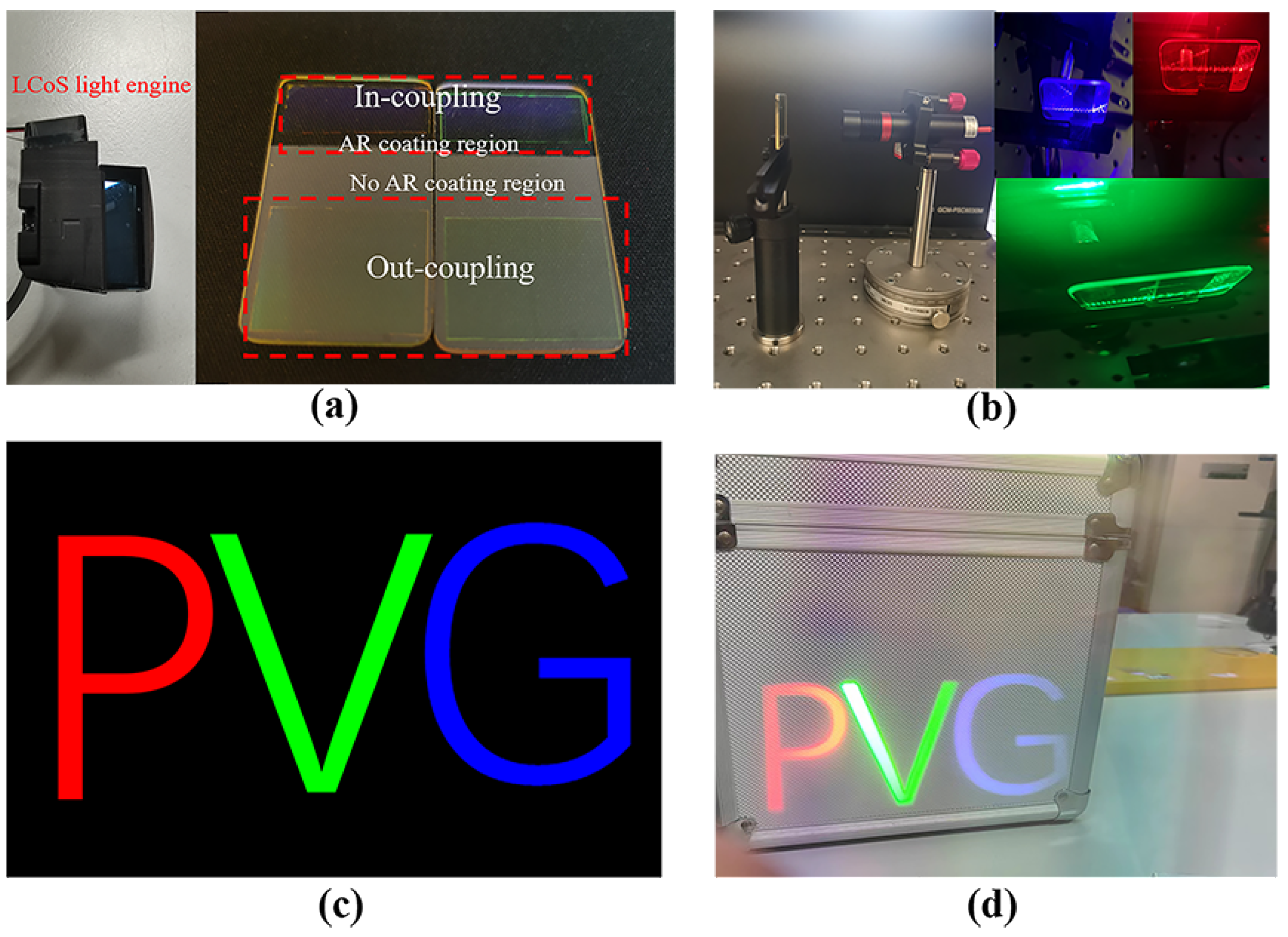
As mentioned before, to prevent crosstalk, we set the two waveguides to have different polarization responses. Also, to prevent reflection loss from the glass surface due to tilted incidence, we coated the glass substrate with the anti-reflection (AR) film in the in-coupling grating region. The prepared waveguide samples are shown in
Figure 8a (Right). The refractive index of the substrate used here was 1.57, and each waveguide contained in-coupling gratings and out-coupling gratings. We can see from the figure that the transmittance near the in-coupling grating is significantly higher than the rest of the waveguide. We used lasers with wavelengths of 630 nm (red), 532 nm (green) and 457 nm (blue) as incident light tilted at 27° into the in-coupling grating to observe the coupling transmission function of the prepared waveguide, and the photographs taken are shown in
Figure 8b. A simple demonstration model was assembled, with the laser built on a rotating table. The three wavelengths of light can propagate within the waveguides, demonstrating the good coupling capability of the waveguides.
To verify the display effect, we used a 45° FOV LCoS light engine (
Figure 8a (Left)). The input image of the microdisplay is shown in
Figure 8c, and the final imaging effect is shown in
Figure 8d. It can be seen that the resulting image contains the color information of red, green and blue, while the black background of the original image becomes transparent in the resulting virtual image so that the human eye can observe the surrounding environment through the waveguide without hindrance.


 ,
, 

