Article

Improving Strength-Ductility via Short Austenitization in a Low-Carbon Carbide-Free Bainitic Steel

1
The State Key Laboratory of Rolling and Automation, Northeastern University, Shenyang 110819, China
2
Department of Materials Physics and Chemistry, School of Materials Science and Engineering, Northeastern University, Shenyang 110819, China
*
Authors to whom correspondence should be addressed.
Crystals 2022, 12(11), 1636; https://doi.org/10.3390/cryst12111636
Submission received: 30 October 2022 / Revised: 10 November 2022 / Accepted: 11 November 2022 / Published: 14 November 2022
(This article belongs to the Special Issue Advances in High Strength Steels)

Abstract

:
The strength and ductility of low-carbon carbide-free bainitic (CFB) automotive steel are not good enough. In this study, a short austenitization (SA) process in conjunction with isothermal bainitic transformation was adopted to refine the bainitic ferrite lath, thus improving the mechanical properties of low-carbon CFB steel. The microstructure evolution was traced by dilatometric measurements and microstructure characterization, which revealed the refined microstructure by SA process. Besides, the deformation behaviors of the studied steels were analyzed, indicating that the improved work hardening capability by refined bainitic ferrite lath and more stable austenite were responsible for the better strength-ductility match. The CFB steel treated by SA process exhibits a high tensile strength of ~1180 MPa, and its elongation of 22.6% is comparable with commercial QP980 steel.

1. Introduction

The carbide-free bainitic (CFB) steels have received considerable attention over the past few decades due to the well-balanced combination of strength and ductility [1,2], which satisfy the ever-increasing demands for automobile steels to fulfill the requirement in reducing carbon dioxide emissions and improving fuel efficiency. The CFB steels also have good cold stamping and cold forming properties [3]. Their excellent mechanical properties are attributed to the fine-scale microstructure composed of bainitic ferrite lath and retained austenite without cementite precipitation [4,5,6]. The higher carbon content is primarily for the fine-scale microstructure; it allows bainitic transformation at low temperature to form tiny bainitic ferrite lath and stabilizes the retained austenite after this transformation. Hence, many efforts have been conducted to investigate the medium-to-high carbon CFB steels [7,8,9,10].
However, there are some undesirable factors introduced by the higher carbon content in carbide-free bainitic steels. On one hand, the excessively long isothermal holding times at low temperature for the bainitic transformation limit the industrial application [11]. On the other hand, the high carbon content has a deteriorating effect on the weldability, which is unsatisfactory for structural components that require welding [12]. Thus, some studies focus on the designing of low-carbon CFB steel in recent years [13,14,15]. Caballero et al. [16] and Hell et al. [17] have designed a series of CFB steels with carbon content between 0.2 and 0.3 wt.% based on thermodynamic and kinetic models. Even though a microstructure consisting of bainite ferrite and retained austenite was obtained in low-carbon CFB steel, bainitic ferrite laths coarsening occurred, thus depriving the favorable mechanical properties by fine microstructure. Some studies were attempted to modify the process of CFB steels for refining the bainitic ferrite lath and thus improving mechanical properties. Qian et al. [18] reported that the introduction of pre-formed martensite could accelerate the subsequent bainitic transformation kinetics, reduce the thickness of bainitic ferrite lath and significantly enhance the impact toughness and tensile properties. The two-step isothermal bainitic transformation process was adopted in some studies for refining bainitic ferrite lath, and it involves forming a certain amount of bainite at a higher temperature, followed by isothermal holding at a lower temperature [19,20]. However, the above-mentioned methods are costly or complex, which are not favorable for the industrial production. Therefore, a suitable process is required for optimizing the microstructure of low-carbon CFB steel.
The thickness of bainitic ferrite is determined by the driving force and the strength of prior austenite [21]. It is thus believed that strengthening austenite could refine the final microstructure of CFB steel. In addition, the features (fraction, size, and morphology) of retained austenite are critical for the mechanical properties of CFB, which is also affected by prior austenite. In the present work, a short austenitization (SA) process was adopted for the adjustment in prior austenite of a high-strength low-carbon CFB steel. The effect of the SA process on the microstructure evolution and mechanical properties was investigated in detail. Besides, the SA process was designed based on the industrial continuous annealing lines. In view of the low cost and process feasibility, this study will provide guidance for the industrial use of bainitic steels.

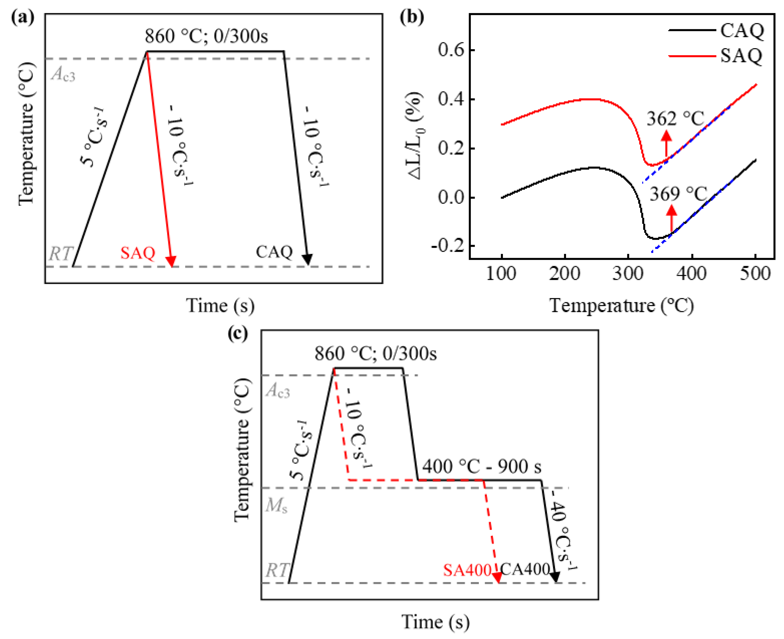
2. Experimental Procedure

The chemical composition of the steel applied in this work was Fe-0.23C-2.85Mn-1.28Si (in wt.%). A 150 kg ingot was cast using a vacuum induction furnace, and slabs with a cross-section of 40 × 100 mm2 were forged and finally cut into blocks. After homogenizing at 1200 °C for 2 h, the blocks were hot rolled into plates with a thickness of 3 mm through seven passes at a finished rolling temperature of about 900 °C. Subsequently, the steel was cooled in a furnace to room temperature for obtaining a microstructure of ferrite and pearlite. Finally, the hot-rolled plate was surface descaled and cold rolled to 1.5 mm.
Dilatometric measurements were carried out using a DIL 805A∙D−1 dilatometer (Bähr D805, Hüllhorst, Germany) equipped with quartz push-rods. The samples with dimensions of 10 × 4 × 1.5 mm3 were processed along the rolling direction of the cold-rolled plate. An S-type thermocouple was welded on the surface of the samples to monitor the temperature, and Argon (Ar) with high purity was supplied for cooling. To determine the Ms temperature of different austenitization processes, the samples were heated to 860 °C and isothermal held for 300 s (CA) and 0 s (SA), followed by Ar cooling to ambient temperature at a cooling rate of 10 °C∙s−1 (Figure 1a), referred to as CAQ and SAQ, respectively. As shown in Figure 1b, the Ms temperatures of the CAQ and SAQ heat are 369 °C and 362 °C, respectively, which were determined by the common tangent method [22]. Besides, these samples were also used to measure the prior austenite grain size (PAGS). The heat treatment processes applied in the current study are shown in Figure 1c. After austenitizing, samples were rapidly cooled down to the austempering temperature (400 °C) at a cooling rate of 10 °C∙s−1 and held for 900 s before quenching to ambient temperature, referred to as CA400 and SA400, respectively.
Samples with dimensions of 1.5 × 60 × 150 mm3 were cut from the cold-rolled sheets. The parameters of heat treatment were designed based on the dilatometry results. The samples were heated to 860 °C for austenitizing in an air furnace with a heating rate of 5 °C∙s−1 and held for 300 s and 0 s, respectively. Then, they were transferred to a salt bath of 400 °C and held for 900 s, followed by water quenching to ambient temperature. The temperature of each sheet was monitored by a K-type thermocouple welded on the surface.
In addition to the tension to failure, various true strain levels of 0.02, 0.05, 0.08, 0.10, and 0.14 were performed for further investigation of the microstructure evolution during tensile deformation. The rectangular sample for the tensile test had a thickness of 1.5 mm, a gauge length of 50 mm, and a gauge width of 12.5 mm, machined in the rolling direction according to the ASTM A370-21 standard [23]. The surface oxide layer of the tensile specimen was removed by pickling after heat treatment. Tensile tests were conducted using a SANS CMT-3000 tensile machine with a cross-head speed of 2 mm∙min−1 (nominal strain rate of ~5 × 10⁻⁴ s−1) at ambient temperature. Three samples were repeated for each condition.
The prior austenite grain boundaries were revealed using a saturated picric acid solution with wetting agents at 65 °C and observed in optical microscope (OM). The microstructure was characterized by an electron probe microanalyzer (EPMA). The samples for the EPMA observation were etched with a 4 vol.% nital after mechanical grinding and polishing. Electron backscatter diffraction (EBSD) experiments were performed with a scanning step size of 30 nm. AZtec software was used to complete the data collection and subsequent processing. EBSD samples were mechanically ground and then electrolytically polished in a 10% perchloric acid solution at 20 V for 20 s.
The volume fraction of austenite and its carbon content of samples before deformation, after interrupted deformation, and after fracture were measured by X-ray diffraction with Cu-Kα radiation run at 40 kV and 100 mA, scanning from 40° to 101° at a speed of 2°∙min−1. The volume fraction of austenite was analyzed by the following equation [24]:
V γ = 1.4 I γ I α + 1.4 I γ
where Vγ represents the volume fraction of austenite, Iγ and Iα were achieved from the mean integral intensities of the (200), (220), and (311) austenite peaks and the (200), (211) ferrite peaks, respectively. The carbon content in austenite was estimated by the following equation [25]:
α γ = 3.556 + 0.0453 x c + 0.00095 x M n + 0.0056 x A l
where xC, xMn, and xAl represent the concentration (wt.%) of carbon, manganese, and aluminum in austenite, respectively, and αγ is the lattice parameter of austenite.

3. Results and Discussion

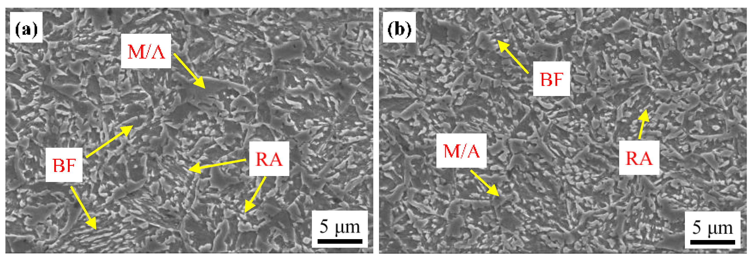
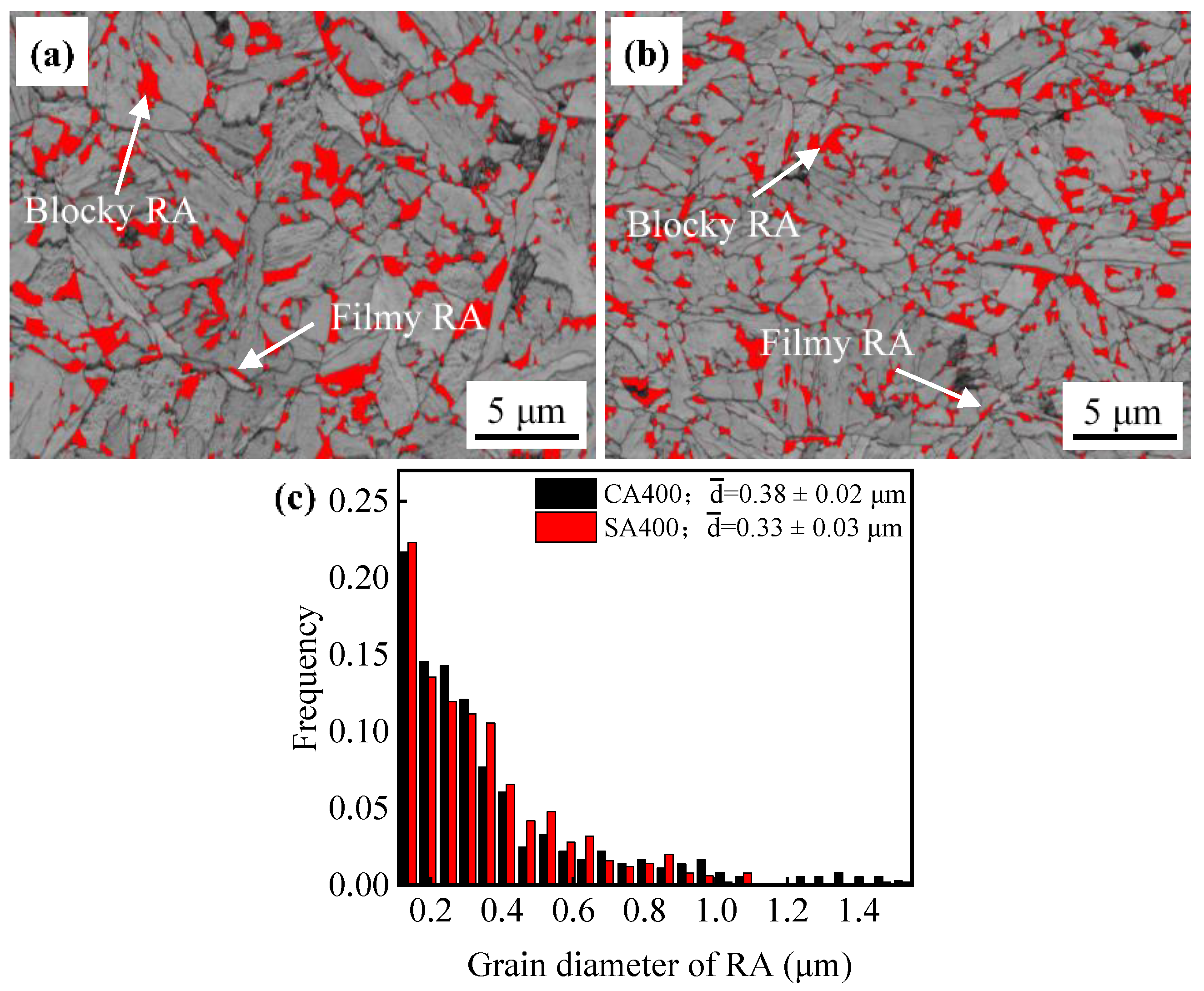
3.1. Microstructure Evolution

The optical micrographs of samples CAQ and SAQ revealed that the PAGS was obviously refined by SA process (Figure 2a,b). The grain sizes were normally distributed, and the average PAGSs measured with Nano Measure software according to the linear intercept method were 10.8 ± 4.0 μm and 4.4 ± 2.0 μm for samples CAQ and SAQ, respectively (Figure 2c). The refinement in PAGS by the SA process would significantly affect the subsequent bainitic transformation during the austempering process.
After the austempering treatment in Figure 1a, multiphase microstructures of bainitic ferrite, retained austenite and martensite were obtained in both samples SA400 and CA400 (Figure 3). No allotriomorphic ferrite or pearlite was observed, indicating that the austenite did not decompose before austempering. This was also verified by dilatometry curves, which show no change in the slope before isothermal holding at 400 °C (Figure 4a). There was a dramatic expansion during the isothermal holding process at 400 °C, resulting from the bainitic transformation (Figure 4). Besides, carbide was not precipitated during this process due to the high silicon addition. Thus, the bainitic ferrite was the primary phase in both samples (Figure 3). Subsequently, slight slop changes occurred at the final cooling stage, corresponding to the martensitic transformation (Figure 4a). The start temperature of martensitic transformation (Ms’) was estimated to be 186 °C and 151 °C for samples CA400 and SA400, respectively, much lower than the initial Ms (Figure 1b and Figure 4a). This confirms that the austenite became more stable after the austempering process. Although the two samples have similar microstructure constitutions, the size and morphology of these phases are diverse.
The most obvious distinction in microstructure of two samples is the size of bainitic ferrite plate, determined by the bainitic transformation of prior austenite. The bainitic transformation is proceeded by incomplete reaction; and it is started with a sub-unit nucleation at the grain boundary of austenite, and then it lengthens until restrained by the plasticity deformation in austenite [26]. With the proceeding of bainitic transformation, the prior austenite was subdivided by bainitic ferrite, and the transformation will be terminated when the size of retained austenite is less than the critical size for bainitic transformation [27]. Thus, the bainitic transformation finishes firstly in SA400 due to the finer PAGS (Figure 4b). After the bainitic transformation, the bainitic ferrite in sample SA400 is shorter and thinner than that in sample CA400 (Figure 3). The shorter bainitic ferrite is attributed to the restriction effect of prior austenite boundaries on its lengthening. The thickness of bainitic ferrite plate in SA400 was measured to be 278 ± 12 nm, while that in CA400 was measured to be 407 ± 8 nm. The thickness of bainitic ferrite is significantly affected by the austenite strength and driving force [28,29]. The two samples were treated by the same austempering process, and thus the influence of driving force on the different thicknesses was ignored. There was not enough time for the dynamic recovery of dislocation during the SA process, resulting in more dislocations being retained in the prior austenite in sample SA400. So, this austenite has higher yield strength with the contribution of dislocation strengthening, leading to the smaller thickness of bainitic ferrite. Azuma [30] developed a quantitative model for estimating the plate thickness. The calculated plate thickness of CA400 was 409 nm based on this model, which is consistent with the measured results.
The retained austenite after austempering partly transformed to martensite, revealed as M/A in Figure 3. The lower Ms’ temperature of sample SA400 implies that this austenite is stabilizer due to the finer size (Figure 4a). This also leads to a reduction in M/A size (Figure 3). The volume fractions of austenite in samples CA400 and SA400 were estimated to be 11.5% and 10.2%, respectively, by EBSD measurements (Figure 5), which are smaller than the fractions of 14.5% and 16.1% obtained by XRD results. There are two morphologies of austenite in samples CA400 and SA400 at ambient temperature, namely blocky austenite, located between the unparallel bainite sheaves or at the prior austenite boundaries, and filmy austenite distributed between bainitic ferrite (Figure 3 and Figure 5). A previous study has elucidated that not all thin film-like austenite could be identified because of the limitation of EBSD resolution, especially in the size range of 20–100 nm [31]. Compared with the sample CA400, the reduced size of austenite in SA400 is beneficial for the austenitic mechanical stabilization. As shown in Figure 5c, the grain size of austenite in SA400 and CA400 is 0.33 ± 0.03 μm and 0.38 ± 0.02 μm, respectively. More blocky austenite could be observed in CA400. The carbon content in austenite is 1.15 wt.% in sample SA400, higher than that of 1.02 wt.% in sample CA400, indicating the higher chemical stability of austenite.

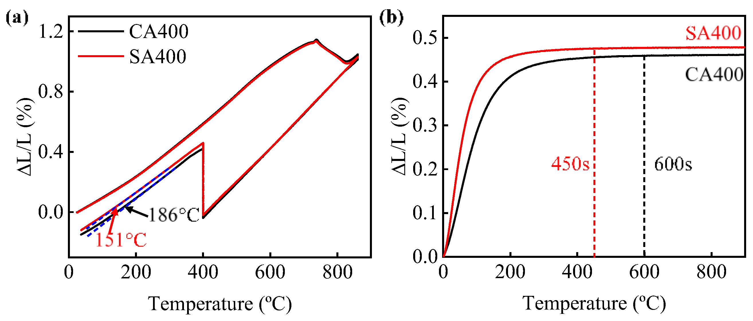
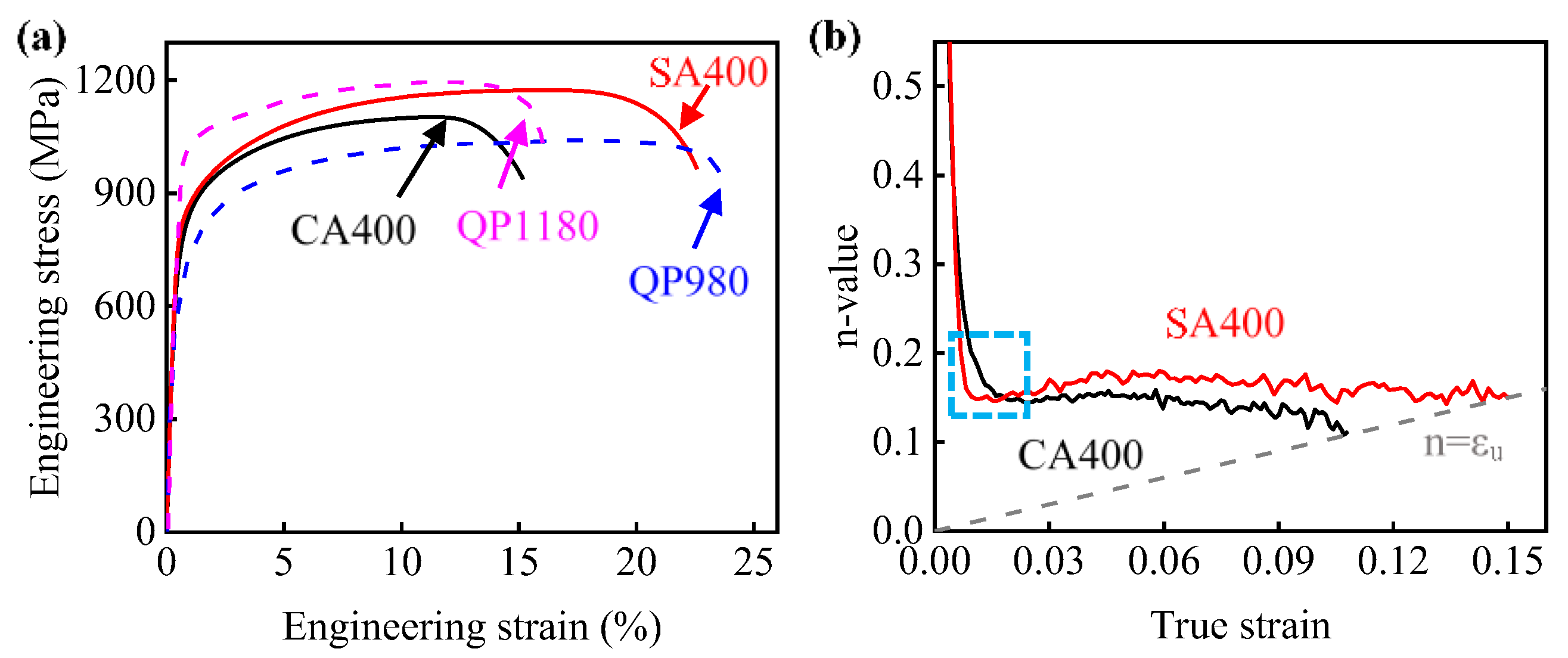
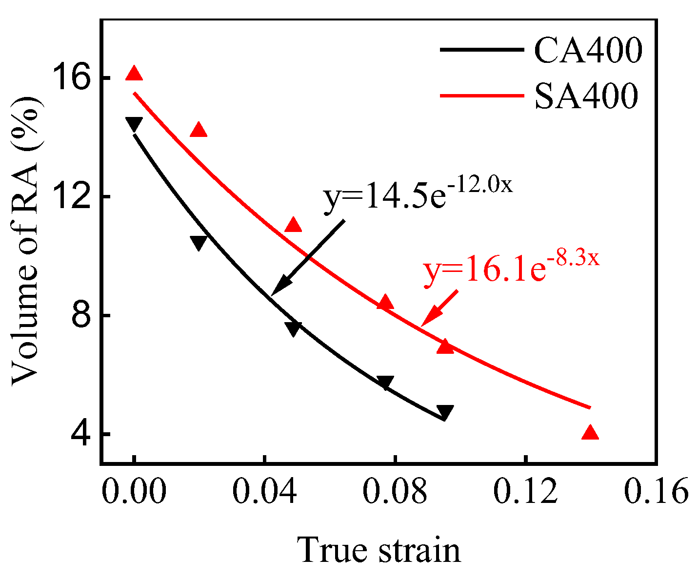
3.2. Improved Strength-Ductility Match by SA

The engineering stress-strain curves of samples CA400 and SA400 are presented in Figure 6a, while the mechanical properties are summarized in Table 1. Two samples show continuous yield behavior, which is attributed to the activation of many movable dislocations [32]. The high yield strengths above 700 MPa were obtained in two CFB steels. In addition, sample SA400 showed higher tensile strength of 1174 ± 7 MPa and elongation of 22.6 ± 0.5% than those of sample CA400. Compared to commercial QP980 steel, the ultimate tensile strength of samples SA400 was increased by more than 100 MPa, while the elongation was essentially equivalent [33]. In addition, the elongation of samples SA400 was approximately 50% higher than that of the commercial QP1180 steel (Figure 6a) [34].
The enhanced tensile strength of sample SA400 is related with the optimized work hardening behavior. Other than the monotonous decreasing in sample CA400, the n-value of sample SA400 presents a slight recovery, and then becomes constant with the increasing strain (Figure 6b). For the present CFB steel, their work hardening behavior should be determined by the dislocation slipping and the TRIP effect. Firstly, the work hardening rate is related with the evolution rate of dislocation. The reduced size of bainitic ferrite gives a small mean free path for dislocation glide, and thus a bigger dislocation accumulation rate. This contributes to the higher n-value of sample SA400. Secondly, the austenite is significantly consumed during the deformation process (Figure 7). Although the austenite grain size unlikely has any significant effect on strength [21], it is believed that the work hardening behavior at this stage is significantly influenced by the TRIP effect, which is determined by the carbon content, morphology, size, and stress state of austenite [35,36,37,38]. The variation in the volume fraction of the austenite at different true strain levels was measured by XRD (Figure 7), which can be reflected by applying the following equation [39,40]:
f γ = f γ 0 exp ( k ε )
where fγ0 is the volume fraction of austenite before deformation, fγ is the austenite fraction at strain ε, and k represents the stability of austenite. The k values are about 12.0 and 8.3 for samples CA400 and SA400, respectively, which reveals that the austenite in sample SA400 has a higher stability due to the smaller size and more carbon enrichment. According to previous works [41,42], the blocky austenite in two samples transformed at low strain level due to the lower stability, and the TRIP effect of the austenite with different sizes gradually happened. As the austenite is more stable in sample SA400, its TRIP effect impels the work hardening to a high strain level. Thus, higher work hardening ability was obtained by sample SA400. The higher work hardening capability is responsible for the enhanced tensile strength of sample SA400 (Figure 6a).
Meanwhile, the total elongation increases by 7.4% by conducting SA process (Figure 6a). It is well known that the transformation of austenite into martensite delays the necking by TRIP effect [43]. Besides, the voids formation in such CFB steels generally initiates at the region of hard martensite, as the brittle failure of martensite offers the nuclei for void growth [44]. Less martensite was obtained in sample SA400 than that in sample CA400 at the same strain, because of the lower Ms´ and postponed TRIP effect, and thus suppressed the formation of voids. Consequently, better strength and ductility has been achieved in the sample SA400 treated by SA process.

4. Conclusions

In this work, a SA process based on industrial continuous annealing lines was designed for the development of low-carbon CFB steel with improved strength and ductility. The microstructure evolution during this process was investigated, and its influence on the mechanical properties was discussed in detail. The main conclusions are as follows:
(1)
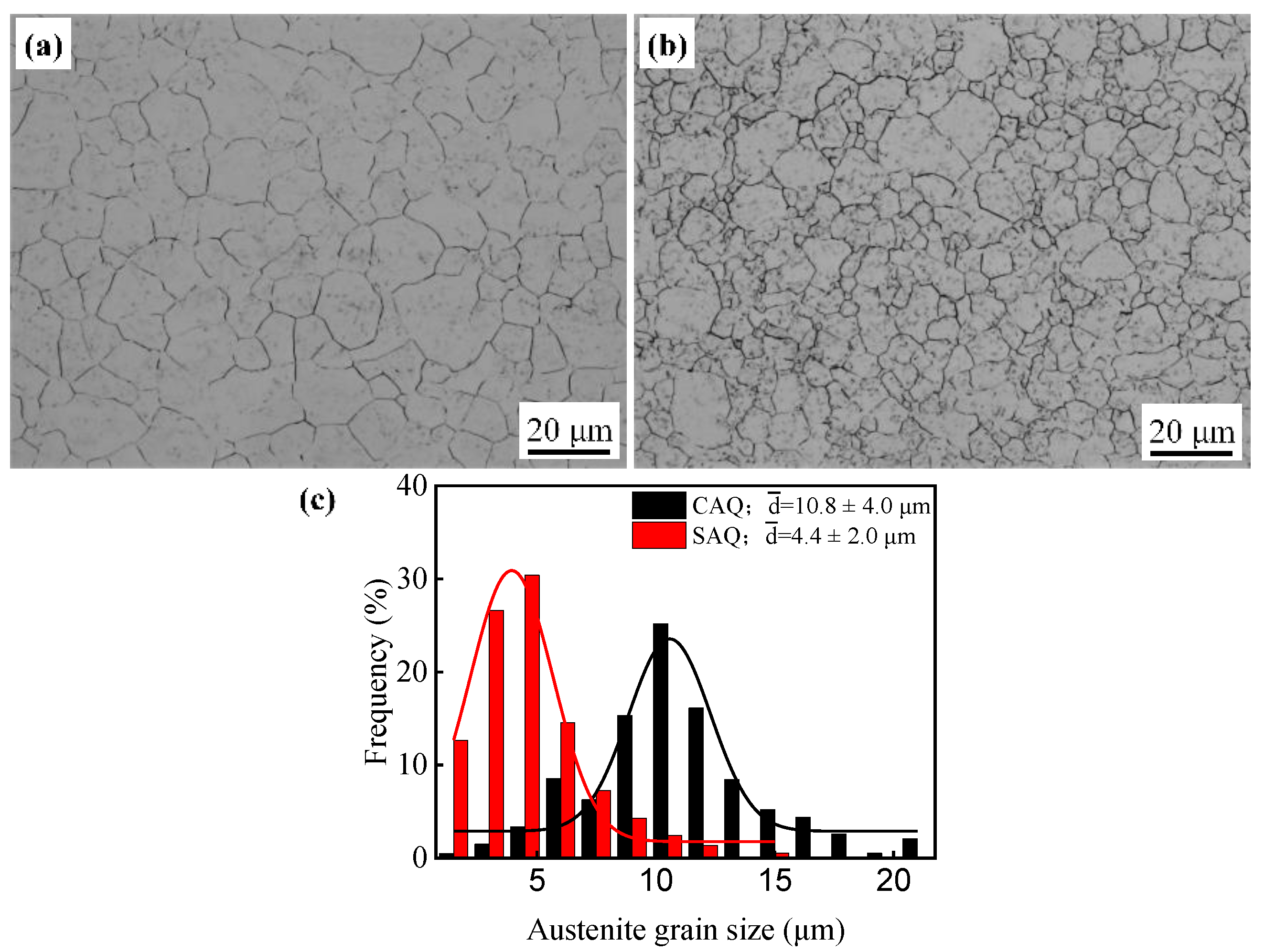
The average PAGS was refined from 10.8 ± 4.0 μm to 4.4 ± 2.0 μm via the SA process. The fined PAGS not only reduces the size of bainitic ferrite lath, but also improves the stability of retained austenite.
(2)
A higher strength and ductility (tensile strength of 1174 MPa and elongation of 22.6%) have been achieved by adopting the SA process, which is comparable or even better compared with commercial QP980 and QP1180 steels. The enhanced work hardening capability, by more efficient TRIP effect and refined bainitic ferrite lath, is responsible for the simultaneously improved strength and ductility. Besides, less martensite in SA400 is also beneficial for the high ductility.

Author Contributions

Conceptualization, J.L. and H.Y.; methodology, J.L. and D.Y.; validation, P.C. and H.Y.; investigation, J.L. and D.Y.; data curation, J.L. and P.C.; writing—original draft preparation, J.L.; writing—review and editing, J.L., P.C. and H.Y.; supervision, H.D.; project administration, H.Y.; funding acquisition, P.C. and H.Y. All authors have read and agreed to the published version of the manuscript.

Funding

This research was funded by National Natural Science Foundation (No. 52101128), National Key R&D Program (No. 2018YFE0306102), Postdoctoral Science Foundation (No. 2022M710021), Fundamental Research Funds for the Central University (No. N2202007) and Postdoctoral Research Fund of Northeastern University of China (No. 20220202).

Data Availability Statement

Data is contained within the article.

Conflicts of Interest

The authors declare no conflict of interest.

References

  1. Takayama, N.; Miyamoto, G.; Furuhara, T. Chemistry and three-dimensional morphology of martensite-austenite constituent in the bainite structure of low-carbon low-alloy steels. Acta Mater. 2018, 145, 154–164. [Google Scholar] [CrossRef]
  2. Rampelberg, C.; Allain, S.Y.P.; Geandier, G.; Teixeira, J.; Lebel, F.; Sourmail, T. Carbide-free bainite transformations above and below martensite start temperature investigated by in-situ high-energy X-ray diffraction. JOM 2021, 73, 3181–3194. [Google Scholar] [CrossRef]
  3. Caballero, F.G.; Allain, S.; Cornide, J.; Puerta Velásquez, J.D.; Garcia-Mateo, C.; Miller, M.K. Design of cold rolled and continuous annealed carbide-free bainitic steels for automotive application. Mater. Des. 2013, 49, 667–680. [Google Scholar] [CrossRef] [Green Version]
  4. Garcia-Mateo, C.; Caballero, F.G. Ultra-high-strength bainitic steels. ISIJ Int. 2005, 45, 1736–1740. [Google Scholar] [CrossRef] [Green Version]
  5. Cornide, J.; Garcia-Mateo, C.; Capdevila, C.; Caballero, F.G. An assessment of the contributing factors to the nanoscale structural refinement of advanced bainitic steels. J. Alloys Compd. 2013, 577, S43–S47. [Google Scholar] [CrossRef]
  6. Eres-Castellanos, A.; Hidalgo, J.; Zorgani, M.; Jahazi, M.; Toda-Caraballo, I.; Caballero, F.G.; Garcia-Mateo, C. Assessing the scale contributing factors of three carbide-free bainitic steels: A complementary theoretical and experimental approach. Mater. Des. 2021, 197, 109217. [Google Scholar] [CrossRef]
  7. Garcia-Mateo, C.; Caballero, F.G.; Bhadeshia, H.K.D.H. Mechanical Properties of Low-Temperature Bainite. Mater. Sci. Forum 2005, 500–501, 495–502. [Google Scholar] [CrossRef] [Green Version]
  8. Kumar, A.; Singh, A. Mechanical properties of nanostructured bainitic steels. Materialia 2021, 15, 101034. [Google Scholar] [CrossRef]
  9. Yang, J.; Wang, T.S.; Zhang, B.; Zhang, F.C. Microstructure and mechanical properties of high-carbon Si–Al-rich steel by low-temperature austempering. Mater. Des. 2012, 35, 170–174. [Google Scholar] [CrossRef]
  10. Gong, W.; Tomota, Y.; Harjo, S.; Su, Y.H.; Aizawa, K. Effect of prior martensite on bainite transformation in nanobainite steel. Acta Mater. 2015, 85, 243–249. [Google Scholar] [CrossRef]
  11. Garcia-Mateo, C.; Caballero, F.G.; Bhadeshia, H.K.D.H. Development of Hard Bainite. ISIJ Int. 2003, 43, 1238–1243. [Google Scholar] [CrossRef] [Green Version]
  12. Caballero, F.G.; Santofimia, M.J.; Garcia-Mateo, C.; Chao, J.; García de Andrés, C. Theoretical design and advanced microstructure in super high strength steels. Mater. Des. 2009, 30, 2077–2083. [Google Scholar] [CrossRef] [Green Version]
  13. Hasan, S.M.; Ghosh, M.; Chakrabarti, D.; Singh, S.B. Development of continuously cooled low-carbon, low-alloy, high strength carbide-free bainitic rail steels. Mater. Sci. Eng. A 2020, 771, 138590. [Google Scholar] [CrossRef]
  14. Lan, H.F.; Du, L.X.; Misra, R.D.K. Effect of microstructural constituents on strength–toughness combination in a low carbon bainitic steel. Mater. Sci. Eng. A 2014, 611, 194–200. [Google Scholar] [CrossRef]
  15. Yang, H.S.; Bhadeshia, H.K.D.H. Designing low carbon, low temperature bainite. Mater. Sci. Technol. 2013, 24, 335–342. [Google Scholar] [CrossRef]
  16. Caballero, F.G.; Santofimia, M.J.; Capdevila, C.; Garcia-Mateo, C.; García de Andrés, C. Design of advanced bainitic steels by optimisation of TTT diagrams and T0 curves. ISIJ Int. 2006, 46, 1479–1488. [Google Scholar] [CrossRef] [Green Version]
  17. Hell, J.C.; Dehmas, M.; Allain, S.; Prado, J.M.; Hazotte, A.; Chateau, J.P. Microstructure-properties relationships in carbide-free bainitic steels. ISIJ Int. 2011, 51, 1724–1732. [Google Scholar] [CrossRef] [Green Version]
  18. Qian, L.H.; Li, Z.; Wang, T.L.; Li, D.D.; Zhang, F.C.; Meng, J.Y. Roles of pre-formed martensite in below- Ms bainite formation, microstructure, strain partitioning and impact absorption energies of low-carbon bainitic steel. J. Mater. Sci. Technol. 2022, 96, 69–84. [Google Scholar] [CrossRef]
  19. Long, X.Y.; Kang, J.; Lv, B.; Zhang, F.C. Carbide-free bainite in medium carbon steel. Mater. Des. 2014, 64, 237–245. [Google Scholar] [CrossRef]
  20. Wang, X.L.; Wu, K.M.; Hu, F.; Yu, L.; Wan, X.L. Multi-step isothermal bainitic transformation in medium-carbon steel. Scr. Mater. 2014, 74, 56–59. [Google Scholar] [CrossRef]
  21. Bhadeshia, H.K.D.H. Bainite in Steels: Theory and Practice, 3rd ed.; Maney Publishing: London, UK, 2015. [Google Scholar] [CrossRef]
  22. García de Andrés, C.; Caballero, F.G.; Capdevila, C.; Álvarez, L.F. Application of dilatometric analysis to the study of solid–solid phase transformations in steels. Mater. Charact. 2002, 48, 101–111. [Google Scholar] [CrossRef] [Green Version]
  23. ASTM 370–21; Standard Test Methods and Definitions for Mechanical Testing of Steel Products. ASTM International: West Conshohocken, PA, USA, 2021. [CrossRef]
  24. Zinsaz-Borujerdi, A.; Zarei-Hanzaki, A.; Abedi, H.R.; Karam-Abian, M.; Ding, H.; Han, D.; Kheradmand, N. Room temperature mechanical properties and microstructure of a low alloyed TRIP-assisted steel subjected to one-step and two-step quenching and partitioning process. Mater. Sci. Eng. A 2018, 725, 341–349. [Google Scholar] [CrossRef]
  25. Vandijk, N.; Butt, A.; Zhao, L.; Sietsma, J.; Offerman, S.; Wright, J.; Vanderzwaag, S. Thermal stability of retained austenite in TRIP steels studied by synchrotron X-ray diffraction during cooling. Acta Mater. 2005, 53, 5439–5447. [Google Scholar] [CrossRef]
  26. Bhadeshia, H.K.D.H.; Edmonds, D.V. The mechanism of bainite formation in steels. Acta Metall. 1980, 28, 1265–1273. [Google Scholar] [CrossRef]
  27. Xu, B.Y.; Chen, P.; Chen, X.F.; Wu, D.; Wang, G.D.; Guo, J.Y.; Liu, R.D.; Yi, H.L. The critical prior austenite grain size of bainitic transformation in a δ-TRIP steel. Scripta Mater. 2022. submitted. [Google Scholar]
  28. Caballero, F.G.; Bhadeshia, H.K.D.H. Very strong bainite. Curr. Opin. Solid State Mater. Sci. 2004, 8, 251–257. [Google Scholar] [CrossRef] [Green Version]
  29. Singh, S.B.; Bhadeshia, H.K.D.H. Estimation of bainite plate-thickness in low-alloy steels. Mater. Sci. Eng. A 1998, 245, 72–79. [Google Scholar] [CrossRef]
  30. Azuma, M.; Fujita, N.; Takahashi, M.; Iung, T. Modelling upper and lower bainite transformation in Steels. Mater. Sci. Forum 2003, 426–432, 1405–1412. [Google Scholar] [CrossRef]
  31. Santofimia, M.J.; Nguyen-Minh, T.; Zhao, L.; Petrov, R.; Sabirov, I.; Sietsma, J. New low carbon Q&P steels containing film-like intercritical ferrite. Mater. Sci. Eng. A 2010, 527, 6429–6439. [Google Scholar] [CrossRef]
  32. Barbacki, A. The role of bainite in shaping mechanical properties of steels. J. Mater. Process. Technol. 1995, 53, 57–63. [Google Scholar] [CrossRef]
  33. Yi, H.L.; Sun, L.; Xiong, X.C. Challenges in the formability of the next generation of automotive steel sheets. Mater. Sci. Technol. 2018, 34, 1112–1117. [Google Scholar] [CrossRef]
  34. Wu, Y.; Guo, Y.; Zhang, W.; Li, L. Microstructure evolution and dynamic mechanical behavior of laser welded dissimilar joint between QP1180 and TRIP780. J. Mater. Res. Technol. 2022, 16, 977–987. [Google Scholar] [CrossRef]
  35. Avishan, B.; García -Mateo, C.; Morales-Rivas, L.; Yazdani, S.; Caballero, F.G. Strengthening and mechanical stability mechanisms in nanostructured bainite. J. Mater. Sci. 2013, 48, 6121–6132. [Google Scholar] [CrossRef] [Green Version]
  36. Yi, H.L.; Lee, K.Y.; Bhadeshia, H.K.D.H. Mechanical stabilisation of retained austenite in δ-TRIP steel. Mater. Sci. Eng. A 2011, 528, 5900–5903. [Google Scholar] [CrossRef]
  37. Caballero, F.G.; García-Mateo, C.; Chao, J.; Santofimia, M.J.; Capdevila, C.; García de Andrés, C. Effects of morphology and stability of retained austenite on the ductility of TRIP-aided bainitic steels. ISIJ Int. 2008, 48, 1256–1262. [Google Scholar] [CrossRef] [Green Version]
  38. Xu, N.; Wang, L.; Hu, J.; Liu, H.; Yu, S.; Xu, W. Batch annealing enhances the yield strength of a high quenching temperature Q&P steel through accelerated bainitic transformation. Mater. Sci. Eng. A 2022, 855, 143888. [Google Scholar] [CrossRef]
  39. Shi, J.; Sun, X.J.; Wang, M.Q.; Hui, W.J.; Dong, H.; Cao, W.Q. Enhanced work-hardening behavior and mechanical properties in ultrafine-grained steels with large-fractioned metastable austenite. Scr. Mater. 2010, 63, 815–818. [Google Scholar] [CrossRef]
  40. Sugimoto, K.I.; Kobayashi, M.; Hashimoto, S.I. Ductility and strain-induced transformation in a high-strength transformation-induced plasticity-aided dual-phase steel. Metall. Trans. A 1992, 23, 3085–3091. [Google Scholar] [CrossRef]
  41. Chen, P.; Chen, R.; Li, X.W. Tensile deformation behavior related with strain-induced martensitic transformation in a duplex Fe-Mn-Al-C low-density steel. Mater. Charact. 2022, 189, 111954. [Google Scholar] [CrossRef]
  42. Zhao, F.Y.; Chen, P.; Xu, B.Y.; Yu, Q.; Misra, R.D.K.; Wang, G.D.; Yi, H.L. Martensite transformation of retained austenite with diverse stability and strain partitioning during tensile deformation of a carbide-free Bainitic steel. Mater. Charact. 2021, 179, 111327. [Google Scholar] [CrossRef]
  43. Zackay, V.F.; Parker, E.R.; Farh, D.; Busch, R. The enhancement of ductility in high-strength steels. ASM Trans. Q. 1967, 60, 252–259. [Google Scholar]
  44. McCutcheon, D.B.; Trumper, T.W.; Embury, J.D. Controlled rolling of acicular ferrite plate. Rev. Métallurgie 1976, 73, 143–174. [Google Scholar] [CrossRef]
Figure 1. (a) Quenching processes; (b) dilatation curves of direct quenched samples; (c) schematic illustration of heat-treatment processes. ΔL: the length change; L0: the initial length.
Crystals 12 01636 g001
Figure 2. Effect of heating processes on PAGS: (a) CAQ; (b) SAQ; (c) distribution of PAGS.
Crystals 12 01636 g002
Figure 3. Microstructure of the samples CA400 (a) and SA400 (b). BF: bainitic ferrite; M/A: martensite austenite island; RA: retained austenite.
Crystals 12 01636 g003
Figure 4. (a) The relative change in length of dilatometry samples with temperature during heating, cooling, and isothermal holding processes; (b) the expansion curves of bainitic transformation during austempering at 400 °C.
Crystals 12 01636 g004
Figure 5. Band contrast (BC) maps of sample CA400 (a) and SA400 (b); (c) the grain diameter distribution of RA.
Crystals 12 01636 g005
Figure 6. (a) Engineering strain-stress curves; (b) instantaneous work-hardening (n-value) versus true strain.
Crystals 12 01636 g006
Figure 7. Variation in volume fraction of austenite with true strain.
Crystals 12 01636 g007
Table 1. Tensile properties of the studied samples.
SamplesYS/MPaUTS/MPaTEL/%
CA400740 ± 71102 ± 515.2 ± 0.3
SA400789 ± 91174 ± 722.6 ± 0.5
QP980 [33]634104023.7
QP1180 [34]993119715.9
YS: yield strength; UTS: ultimate tensile strength; TEL: total elongation.
Publisher’s Note: MDPI stays neutral with regard to jurisdictional claims in published maps and institutional affiliations.

