Article

Electro-Acoustic Properties of Scandium-Doped Aluminum Nitride (ScxAl1-xN) Material and its Application to Phononic Crystal-Coupled SAW Devices

1
Photonic Crystals Team, Research Unit in Optics and Photonics–Center for Development of Advanced Technologies (UROP-CDTA), El-Bez, Setif 19000, Algeria
2
MEMS and Sensors Team, Microelectronic and Nanotechnology Division, Center for Development of Advanced Technologies, Cité 20 Août 1956, Baba Hassen 16303, Algeria
3
IEMN, UMR CNRS 8520, University of Lille, 59652 Villeneuve d’Ascq, France
4
Mersin Vocational High School, Electronic and Automation Department, Mersin University, Mersin 33110, Turkey
5
Laboratoire d’Optoélectronique et Composants, Département de Physique, Université Sétif 1, Sétif 19000, Algeria
*
Authors to whom correspondence should be addressed.
Crystals 2022, 12(10), 1431; https://doi.org/10.3390/cryst12101431
Submission received: 10 September 2022 / Revised: 29 September 2022 / Accepted: 3 October 2022 / Published: 10 October 2022
(This article belongs to the Special Issue Advances in Phononic Crystals and Elastic Metamaterials)

Abstract

:
Within the framework of the Density Functional Theory, the elastic, dielectric, and piezoelectric coefficients of w-ScxAl1−xN material were investigated for scandium (Sc) concentrations x = 0 to 0.375. The electro-acoustic properties are used to investigate the frequency response of the SAW delay line, based on the tilt θ° of the normal c-axis of the w-ScxAl1−xN piezoelectric thin film. We found that the piezoelectric response is improved as the Sc concentration increases, which is consistent with existing works in the literature. A 2D-phononic crystal pillars was then grafted on top of the surface, and the dependence of the acoustic band gaps is investigated with the help of the finite element method as a function of the Sc concentration and the tilted angle of w-Sc0.375Al0.625N. It was found that the two first band gaps exhibit a shift toward low frequencies with increasing Sc concentration. Moreover, the second acoustic bandgap is more sensitive to the inclination angle than the first. Furthermore, the insertion loss (S21) of w-Sc0.375Al0.625N is improved by 22 dB at θ° = 60°. The c-axis tilted Sc0.375Al0.625N-SAW delay line coupled with 2D-phononic crystals is a promising structure for low-loss and high-frequency SAW devices.

1. Introduction

Surface acoustic wave (SAW) devices are among the most attractive candidates for modern electronic devices because of their low cost, low losses, and great sensitivity and integrability. These devices have become crucial for mobile telecommunication systems that require high-frequency and low-loss sensing components. In SAW devices, piezoelectric materials are required to convert the incoming electric signal to an acoustic one and then back to electric. One of the most challenging features in producing high-performance SAW devices is to select an appropriate piezoelectric material in combination with a suitable substrate [1,2].
The interest in piezoelectric thin films for electromechanical systems increased after the discovery of aluminum nitride (AlN) with, in particular, the commercial success of the SAW sensors. Most conventional SAW devices made of silicon have been reproduced with enhanced performance using AlN thin-film piezoelectric technology [3].
Unlike other widely used piezoelectric materials such as zinc oxide (ZnO) [4] and lead zirconate titanate (PZT) [5], AlN has good chemical properties, thermal stability, high hardness, and high surface wave velocity, and is compatible with conventional CMOS technology on silicon [6,7,8]. Conversely, AlN piezoelectric thin film has a lower effective piezoelectric constant, which can be improved using specific transition metals as dopants.
Recently, a number of works have been devoted to the AlN doping of scandium (Sc), yttrium (Y), ytterbium (Yb), and other elements to increase the piezoelectric properties and improve the efficiency of SAW devices [9,10,11,12,13,14]. Compared to other transition metals, scandium as a dopant exhibits a structural transition from the wurtzite phase to the rocky phase, which occurs at low alloying concentrations, leading to easily synthesized and more stable alloys. Second, the piezoelectric coefficients are much higher in AlScN than in pure AlN. This can be explained by the fact that, in the growth process of the AlScN thin film, a competition between Al3+ and Sc3+ for coordination with nitrogen is introduced, which weakens the resistance to nitrogen displacement in the crystal structure and increases the volume of the unit cell. Due to this remarkable piezoelectricity property, scandium (Sc)-doped AlN (ScAlN) is extensively used in high-frequency filters, sensors, and micro-electromechanical devices [15,16,17,18]. Basically, the high piezoelectric constant of ScAlN leads to a significant increase in the electro-mechanical coupling factor, thus resulting in a significant improvement in the performance of SAW devices. ScxAl1-xN alloy thin films may represent an alternative material to replace AlN.
M. Akiyama et al. [19,20] found that the piezoelectric coefficient d33 increases from 6 pC/N for pure AlN to 27.6 pC/N for Sc0.43Al0.57N, i.e., at least 500% larger than for AlN. They showed that the piezoelectric response is strongly dependent on the growth temperature. Furthermore, W. Gunilla et al. [21] showed that the electromechanical coupling (kt2), influenced by the Sc concentration, increases from 7% in AlN to 15% in Al0.7Sc0.3N. As an example, Konno Akira et al. [22] reported that, when using a 40% Sc-doped AlN film, the piezoelectric characteristic of Lamb wave resonators is approximately five times higher than in pure AlN.
From the perspective of different applications, ScxAl1-xN thin films have been deposited on several substrates such as Si [23], 6H-SiC [24], diamond [25], and sapphire [26]. In each case, the structures enhance the SAW velocity and the electro-mechanical coupling factor k2. Some examples of SAW devices properties based on ScxAl1-xN/sapphire structures have been investigated using experiments [27] and theories [13,14,28], showing relatively high insertion losses. By comparison, ScxAl1-xN/sapphire structures are promising SAW devices for high-temperature sensor applications [16,29,30].
Additionally, highly c-axis-oriented thin films are useful for surface acoustic device fabrication, as evidenced by the rising electromechanical coupling coefficient of c-axis tilted ScAlN thin films. Many studies witness that the direction of wave propagation and the c-axis tilt angle of scandium-doped aluminum nitride piezoelectric thin films have a major impact on the electromechanical properties of SAW devices [25,31]. Theoretical analysis of the Rayleigh SAW mode showed that (k2), in a tilted ScAlN film on the R-sapphire, is 3.9% at a tilt angle of 90° and 3.7% at a tilt angle of 54° [32]. By comparison, the insertion loss of fabricated IDT/ScAlN tilted at 33°/R-sapphire structure is 34.4 dB, demonstrating that higher electromechanical coupling factor k2 improves the crystal orientation of ScAlN films. The c-axis-tilted ScAlN films with a Sc concentration of 40%, prepared on a silicon substrate via RF magnetron sputtering based on the self-shadowing effect, reach a maximum c-axis tilt angle of 57.4°. In this structure, the electromechanical coupling coefficient (k2) has been increased because of the c-axis tilt angle [33,34].
Furthermore, recent studies have shown that surface acoustic waves (SAWs) have a significant interest in phononic crystals (PnCs) [35,36,37,38], in particular to generate and detect SAW using interdigital transducers [39,40,41]. In such structures, the well-known band gap, in which acoustic waves cannot propagate in any direction of the piezoelectric phononic crystals [42], plays an important role in the design of applications such as demultiplexers [43], filters, and waveguides [44,45,46]. The insertion loss can be improved by −7 dB with PnCs used as reflected gratings [47]. Similarly, as grating sizes are reduced, a novel proposed structure may provide a new idea for resonator, filter, or other possible application designs [48].
We also mention the development of highly sensitive SAW sensors, using nano- or micro-pillar structures, attached like a cantilever between the fingers of the IDT and used as a sensing medium [49]. The interaction of surface elastic waves with 2D phononic crystal (PnCs) on top of piezoelectric substrate has been studied to control the central frequency and the opening of acoustic band gaps [50,51]. Phononic crystals have been recently proposed as a platform for the investigation of the acoustic velocity and/or the density of the liquid filling parts of the structure. The sensing phenomena are based on the high sensitivity to external stimuli (temperature, pressure, nature of the liquid, etc.) of localized modes, associated with defects, appearing inside absolute phononic band gaps. Shaped and pillar-based phononic crystal anchors have recently been used in the field of micro-electromechanical system (MEMS) resonators to reduce anchor losses and improve the quality factor (Q) [52,53,54,55]. It is demonstrated that using pillar-based PnC anchors in AlN lamb wave resonators can reduce the anchor loss and boost the Q factor by 24 times compared to the conventional resonators [55]. Recently, SAW-PnC-based devices with non-metallic pillars have been designed on Si substrate for wide ultrahigh frequency range applications, such as wirelesses communications, filters, and duplexers [56,57,58].
Despite the large number of studies on SAW-PnCs, none of them have examined the effect of ScxAl1-xN or c-tilted ScxAl1-xN on PnCs band gaps. For this purpose, because of the dependence of the elastic properties due to scandium concentration and c-axis tilted angle, we first studied the influence of Sc concentration on elastic, piezoelectric, and dielectric properties using the Density Functional Theory (DFT). Then, we used the calculated values of the elastic parameters to investigate the influence of Sc concentration and c-axis tilt angle of ScxAl1-xN thin films on both the acoustic band gap generated by the pillars structuration, and the insertion loss of the SAW device, i.e., the S21(dB)-scattering parameter.

2. Computational Methods

Density Functional Theory (DFT), in combination with generalized gradient approximation GGA-PBE [59], is used to predict the structural characteristics and elastic coefficients of w-ScxAl1-xN Wurtzite crystals. A Monkhorst–Pack mesh of 5 × 5 × 5 k-points in the Brillouin-zone integral was used with a cutoff energy of 500 eV and total energy convergence threshold of 10−6 eV [60]. The Density Functional Theory Perturbation (DFTP) [61] was used to determine both piezoelectric and dielectric constants of w-ScxAl1-xN in the range of x = 0, 0.125, 0.25, and 0.375, and then, the elastic constants (Cij), the piezoelectric coefficients (eij), and the permittivity tensor (εij) of w-ScxAl1-xN. The physical parameters were introduced in the Finite Element model (COMSOL) to obtain the acoustic band gaps of the 2D ScxAl1-xN pillar-based phononic crystals (PnCs), the mechanical transmission, and the transmission loss S21(dB) of the SAW delay line. The results were compared with the non-structured surface. The same methodology was used in the case of the c-axis tilt angle of w-ScxAl1-xN [62] (see diagram in Figure 1).

3. Results and Discussion

In the first step, we determined the equilibrium geometries, including the lattice parameters (a, c) of w-AlN for a structural optimization. The equilibrium structural parameters were obtained at zero pressure and under the temperatures gathered in Table 1. Our results are in good agreement with both experimental data [63], with an error of about 0.70%, and theoretical values [9,64] (see Table 1).
We then examined the effect of the proportion of Sc on the properties of aluminum scandium nitrite (w-ScxAl1−xN). For this study, we substituted the concentrations of two, four, and six Al by the Sc atoms in a supercell of (2 × 2 × 1) constructed from a w-AlN Wurtzite structure containing 16 atoms, then representing 12.5%, 25%, and 37.5%. In all concentrations (x = 0, 0.125, 0.25, and 0.375), the predicted lattice parameters of w-ScxAl1-xN agree with the experimental [9] and theoretical results [65] (see Table 1).
Furthermore, when the Sc concentration increased, the lattice constants (a and c) increased respectively by 5.6% and 1%, while the c/a ratio decreased by 4.6%. This effect may be due to changes in the bond lengths and angles of the AlN4 tetrahedron, which deforms when Al atoms are replaced by Sc atoms [19,65]. This effect can then be estimated geometrically from the determination of the lattice constants a and c [9]. Theoretical and experimental details of the impact of scandium concentration on bond length can be found in several papers [9,19,65,66]. Again, these results agree with the experimental [19] and theoretical data [65] obtained from the Quantum Expresso (QE) software package with a (3 × 3 × 1) super cell.
Table 1 also compares the single-crystal elastic constants for w-ScxAl1−xN obtained from the proposed functional GGA-PBE for various concentrations x = 0, 0.125, 0.25, 0.375, theoretically [64,65,67,68] and experimentally [69,70,71]. Our result agrees with most of the accessible data, indicating the accuracy of our calculation. The elastic stiffness constants Cij should respect the mechanical stability criteria for hexagonal symmetry, as described below [72]:
(C11C12) > 0 and C44 > 0 (C11 + C12) C33−2C213 > 0
The elastic constants of w-ScxAl1-xN satisfy the above criteria in all compositions over the considered range, indicating that the compounds are mechanically stable. From Figure 2a, we observe that, when the Sc concentration increases, C33 and C11 present an almost linear variation, decreasing from 354 to 220 GPa and from 376 to 282 GPa, respectively, corresponding to a relative decrease of 38 and 25%. Similarly, C44 decreases as a function of the Sc concentration with a relative reduction of 25%. By comparison, doping AlN with Sc increases the mixed compression/shear C12 and C13 elastic constants. This behavior is similar with the observed theoretical [66,73,74] and experimental [9] works. We can therefore conclude that, as the concentration of Sc increases, the material softens along the c-axis, and hardens in the basal plane.

3.1. Piezoelectric and Dielectric Constants

The piezoelectric coefficients eij explain the piezoelectric properties of the material, through the piezoelectric moduli dik and the elastic constants Cij as follows [75]:
e i j   =   k d i k C k j ,   where   = 1 ,   2 ,   3   j = 1 ,   6   and   k = 1 , 6
For the hexagonal material, the tensor eij is given by:
e i j = ( 0 0 0 0 e 15 0 0 0 0 e 15 0 0 e 31 e 31 e 33 0 0 0 )                                                                                                          
d i k = ( 0 0 0 0 d 15 0 0 0 0 d 15 0 0 d 31 d 31 d 33 0 0 0 )  
C i j = ( C 11 C 12 C 13 0 0 0 C 12 C 11 C 13 0 0 0 C 13 C 13 C 33 0 0 0 0 0 0 C 44 0 0 0 0 0 0 C 44 0 0 0 0 0 0 1 2 ( C 11 C 12 ) )                                                      
The dielectric tensor is symmetric and respects all the symmetry operations of the corresponding point group. This limits the number of independent elements in the tensor to a minimum of 1 and a maximum of 6 depending on the crystal symmetry. For a hexagonal crystal it only has two components ( ε 11 ,   ε 33 ) different from zero, expressed as:
ε i j = ( ε 11 0 0 0 ε 11 0 0 0 ε 33 )
DFTP is used to calculate the piezoelectric and dielectric tensors of w-ScxAl1-xN, which are the sum of the ionic and electronic contributions. Table 2 reports our calculated values, which are in good agreement with other theoretical data and measured values.
Figure 2b depicts the evolution of the piezoelectric coefficients (e15, e31, e33) as a function of the Sc concentration. The most striking feature of this graph is the quick evolution of e33, which increases by 67%. By comparison, the two coefficients e15 and e31 show a relative increase of 18 and 2.75%, respectively. This result indicates that the addition of a trivalent dopant (Sc3+) constrains the displacement along the c-axis. Moreover, because the electronegativity of the Sc atom is lower than that of the Al atom, the w-ScxAl1-xN material is more electrovalent, which improves the piezoelectric properties [19].
The dependence of the piezoelectric coefficients e15, e31, and e33 with increasing Sc content is consistent and follows the general trend obtained from previous theoretical results [64,65,67,68] and experimental measurements [9,69,70].
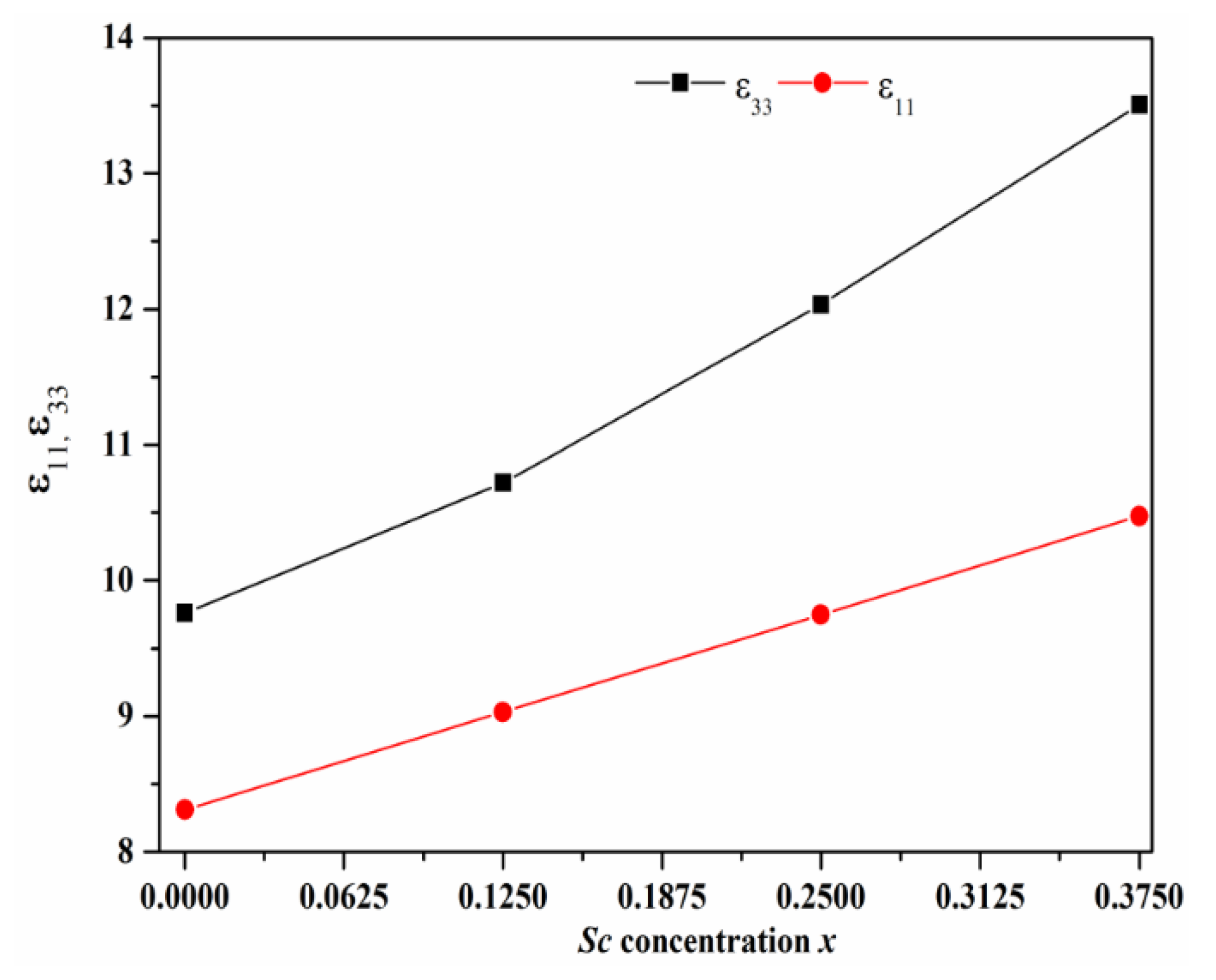
Table 2 shows that our calculated dielectric constants ε11 and ε33 at x = 0% are in good agreement with previous data [68,69,70]. Then, as seen in Figure 3, the two components ε33 and ε11 increase almost linearly with the concentration of Sc [21]. Obviously, ε33 is more sensitive than ε11, increasing by 38% compared to 26%. This is mainly due to the strong lattice polarization induced by the out-of-plane (c-axis) Sc atom.
These results indicate an increasing charge and polarization binding capacity of the compound w-ScxAl1-xN. All these results show an enhanced electromechanical coupling (k2), which justify the selection of w-Sc0.375Al0.625N material for SAW devices.

3.2. Dependence on Electro-Acoustic Parameters of w-Sc0.375Al0.625N with tilted c-Axis Orientation

The description of the dependence of the tilted c-axis orientation angle on the electro-acoustic properties is a very important issue for the growth of films with oriented structure. In order to investigate the inclination angle on the electro-acoustic properties of Sc0.375Al0.625N, a rotation following a clockwise angle θ against the y-axis was considered. The original coordinates (x, y, z) were changed to a set of new coordinates (x, y, z). It was found that the elastic stiffness Cij, the piezoelectric stress eij coefficient, and the dielectric permittivity εij can be computed through properties in original coordinate system (x, y, z) with the help of matrix algebra [76].
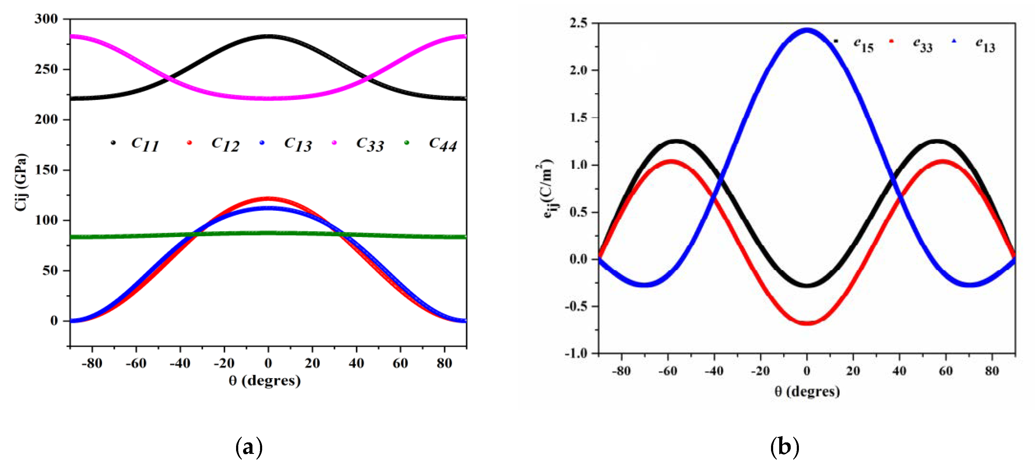
According to Euler’s laws on the rotation, all physical matrices in a new orientation are obtained by a transformation matrices methodology [77]. Figure 4a illustrates the dependence of Cij against the inclination angle θ. It is clearly seen that, when changing θ from −90° to 90°, a symmetric behavior for all Cij is observed at θ = 0°. The increase in θ leads to decreases in C11, C12, and C13. An opposite dependence is observed between C33 and C11 due to the c-axis inclination angle, as these two elements are related to the out-of-plane and in-plane component. It should be mentioned that C44 does not depend on the inclination angle, which can be explained by the fact that x2 and x2 present the same axis.
Figure 4b shows the variation of direct piezoelectric constants eij with the c-axis tilted angle. We observed that e15 and e31 are negative at 0° and behave as a sinus. With the increase of the inclination angle θ, e15 and e31 reach a maximum at 56° and 58° respectively. This dependence was also observed in c-axis-tilted AlN with the same trends [78]. In addition, e33 reaches a maximum at θ = 0°, a minimum at θ = 70°, then becomes zero at 90°, in addition to e15 and e33.
In Figure 4c, we plot the dielectric constants ε11 and ε33 as a function of the c-axis tilted angle θ°. The dielectric constants ε11 and ε33 present an opposite trend with equal values at (θ = 45°). Indeed, the absolute value of ε11 is maximum at θ = 90°, while ε33 component has a maximum at θ = 0°, equivalent to the behavior of undoped AlN [78]. This is attributed to the fact that the x1 axis becomes x3, and x3 coincides with negative x1 when θ is equal to 90°, and is a direct consequence of the Wurtzite crystal structure of group III-Nitrides [79,80].

3.3. FEM Simulation of PnCs Unit Cell Dispersion Modes

In this study, we define a phononic crystal (PnC) made of AlN cylindrical pillars, deposited on a semi-infinite AlN/Al2O3 substrate, arranged in a square lattice. The elementary unit cell, shown in Figure 5a, is repeated periodically in the (x, y) plane with the pillar axis oriented along the z-axis. The filling factor is defined by f = π.r2/a2, where a is the lattice parameter of the phononic crystal and r the radius of the cylindrical pillar. The pillar height is h1, h2 is the thickness of the AlN layer, and h3 is the thickness of the bulk material (Al2O3), chosen to be five times the lattice constant of the PnCs unit cell (h3 = 5 × a) [81].
In the elementary unit cell, we applied, on the upper surface, free mechanical displacement as boundary conditions, whereas the bottom surface of the substrate has fixed boundary conditions (i.e., zero mechanical displacement). On the lateral sides of the unit cell, we applied Bloch–Floquet periodic boundary conditions (PBCs). The Bloch wave vector components (kB) (in the x and y directions) are swept between the high symmetry points of the first irreducible Brillouin zone (Γ-X-M-Γ) represented Figure 5b.
The dispersion curves were computed by plotting the calculated eigenfrequency values versus the wave vector magnitude, swept in the first irreducible Brillouin zone (Figure 5b). The eigenfrequencies and the corresponding vibration modes of the PnC unit cell structure were computed by solving the dispersion relation using the Finite Element Method (FEM), in the COMSOL Multiphysics software. The FEM has been proven to be an efficient tool to obtain dispersion curves and mechanical displacement fields in phononic structures [82]. All calculations were performed with the physical parameters reported in Table 3.
Figure 6 depicts the computed acoustic band structure in the first irreducible Brillouin zone, along the high symmetry directions, for pillars with a relative height h/a, and radius r/a of 30% and 37.5% respectively. The sound line delimits the bulk modes (gray area) from the surface coupled modes, below the line. The latter correspond to SAW modes with an acoustic energy localized at the surface and/or in the pillars. Under those conditions, the blue area represents an acoustic bandgap, extending from 313 to 350 MHz, with an 11% relative bandwidth, generated by local resonances of pillars interacting with the SAW [58].

3.3.1. Effect of the Structural Parameters

The band gaps can be characterized by two key indicators, namely the center frequency fc and the bandgap width Bw. These two indicators determine the operating parameters of the PnCs and are defined as [55]:
f c = ( f u + f l ) / 2 ,   B w = f u f l
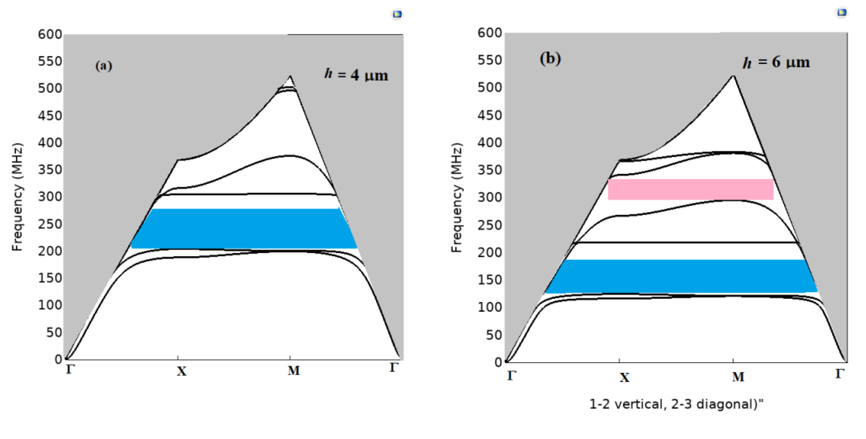
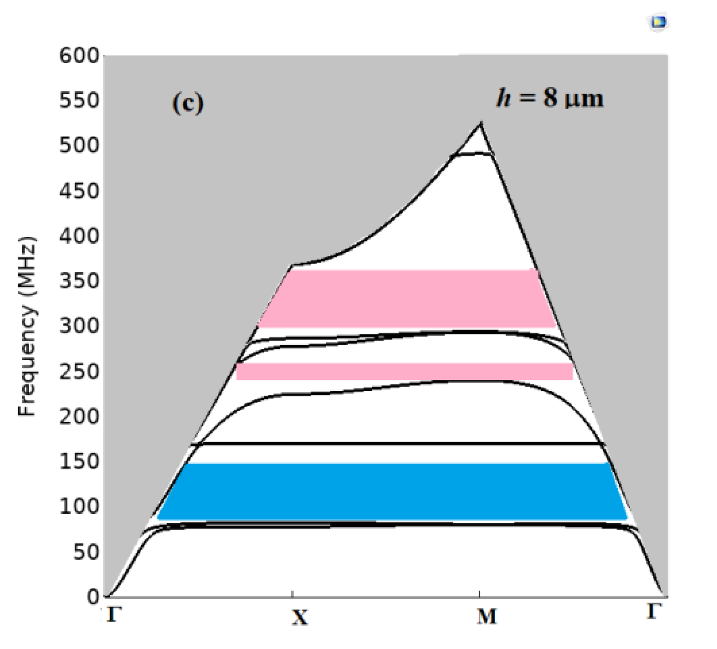
where fu and fl represent respectively the upper and lower frequency limits of the band gap. The band gaps operating parameters have been investigated as a function of the geometrical parameters, namely the pillar’s height (h) and radius (r). Figure 7a–c show the phononic crystal band structure for three different characteristic values of (h), i.e., 4, 6, and 8 µm, with a fixed radius value of r = 3 µm and a = 8 µm. The dependence of the forbidden band according to the height of the pillars is highlighted. The absolute band gap of the SAWs is limited to the domain below the sound line. When h = 4 µm, only one absolute band gap is observed (Figure 7a), whereas two band gaps occur for 6 µm, then three for 8 µm. Additionally, when the height of the pillars h increases, the band gaps downshift toward low frequencies and new band gaps appear. According to [58,83], they can be attributed to local resonance bandgaps.
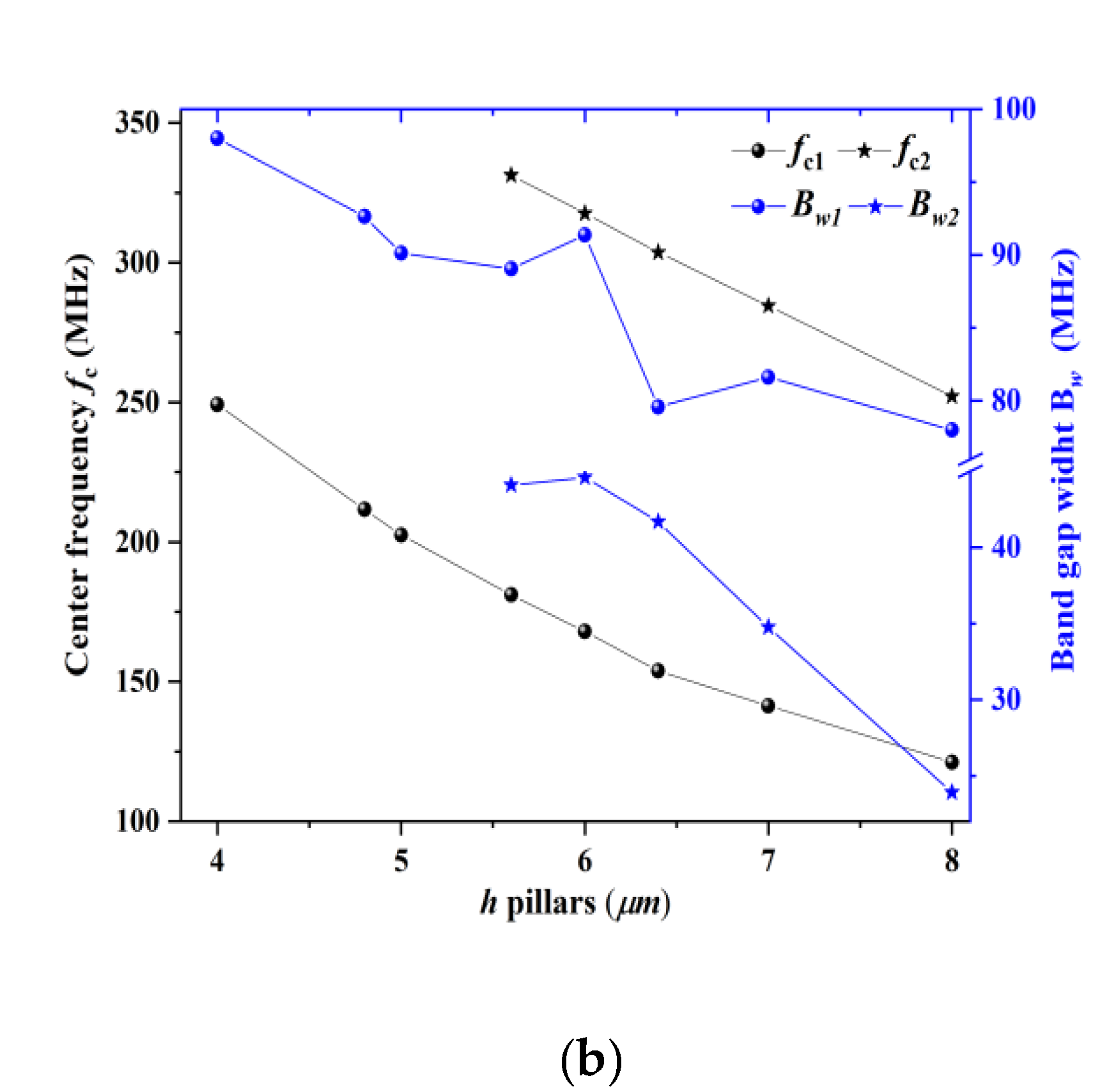
Figure 8a outlines the evolution of the first and second acoustic band gaps with the aspect ratio h/a in the range [0.3, 1]. We find that the height of the pillars plays an important effect on both the width and the frequency position of the gaps. Increasing h shifts the band gaps down toward low frequencies. By comparison, the second acoustic bandgap does not exist until h/a = 0.7. For h/a = 0.7, the first and second acoustic bandgaps now extend from 136 to 225 MHz and from 309 to 352 MHz, respectively. Figure 8b shows, as an example, the variation in fc and Bw of the first and second bandgap as a function of h, keeping constant a = 8 µm and r = 2.6 µm. For the first (resp. second) band gap, the width Bw decreases from 98 MHz (resp. 45 MHz) to 78 MHz (resp. 24 MHz) when h increases from 4 µm (resp. 6µm) to h = 8 µm. Furthermore, as shown in Figure 8b, the center frequency fc1 decreases almost linearly from 339 to 121 MHz when h changes from 2.4 to 8 µm, and fc2 decreases from 331 to 252 MHz when h changes from 5.6 to 8 µm.
By comparison, the influence of the radius r, even if optimized, on the two bandgaps indicators, is low (see Figures S1 and S2, Supplementary Materials). Therefore, h = 6 µm and r = 2.6 µm represent an appropriate choice to obtain the largest acoustic gap openings for SAW-coupled PnCs applications. It is worth noting that modifying the geometrical characteristics of the pillars can modulate the acoustic band gaps of pillar-based PnCs over a large frequency range.

3.3.2. Effect of AlN Doping on the Acoustic Band Gaps

As mentioned in Section 1, the elastic, dielectric, and piezoelectric coefficients of AlN are affected by the doping concentration in Sc which, in consequence, has the potential to affect the acoustic bandgap characteristics, i.e., the frequency position fc and the bandwidth Bw. Indeed, as seen Figure 9a, when the Sc concentration increases, both first and second band gaps exhibit a consequent shift down toward low frequencies, while their widths are slightly modified. This is confirmed by a representation of fc and Bw as a function of the Sc concentration (Figure 9b). From this figure, we notice that the center frequencies vary linearly from 161 to 131 MHz and from 321 to 259 MHz when the Sc concentration increases from 0 to 37.5% for the first and second acoustic band gaps, respectively. Such a variation is due to the acoustic velocity which is modified by the elastic constant Cij and density ρ (g/cm3) of w-ScxAl1-xN. For the two band gaps, the bandgap width (Bw) has been slightly modified, with a variation of −10% for the first gap and +7% for the second.
Finally, we studied the dependence of the acoustic bandgaps on a tilted c-axis orientation angle of a w-Sc0.375Al0.625N PnC-based structure. From the results shown in Figure 10a,b, it is clear that when θ changes from −90° to 90°, a symmetric behavior with respect to θ = 0° is observed for the two acoustic bandgaps, due to the dependence of Cij on the angle of inclination. Additionally, we can see that the second gap is more sensitive to c-axis inclination angle (see Figure 10b). All the modification of the physical parameters can provide a new perspective for controlling SAW-coupled PnC devices and applications.

3.3.3. Analysis of Surface Phononic Modes in the SAW-PnCs

To gains more insight into the involved phononic modes, we report in Figure 11a the dispersion curves of w-Sc0.375Al0.625N pillars with a = 8 µm, h = 6 µm, and r = 2.6 µm, and in Figure 11b the corresponding mechanical displacement field of the first modes, designated by points A, B, C, D, and E. The acoustic branches, passing by A and D, are degenerated because of the x and y polarization modes appearing at the same frequency.
The calculations of the displacement fields of modes A, B, C, and D show that the elastic fields are mostly localized inside the pillars (see Figure 11c). Mode A, occurring at 88 MHz, corresponds to a first-order flexural oscillation of the pillar, either in the sagittal plane (x, z) or in the (y, z) plane. Mode B, at 182 MHz, shows a radial oscillation. Mode C, at f = 205 MHz, is a compressional mode, exhibiting an axial elongation of the pillar in the direction z. Finally, mode D at f = 282 MHz is associated with a second-order flexural mode of the pillar. All these modes interact with the Rayleigh wave and generate dispersion branches of more or less slow group velocity [84,85,86,87]. Mode E at 413 MHz is located over the sound cone, and corresponds to a radiative mode in the substrate, for which the mechanical displacement field penetrates into the bulk of the substrate (w-Sc0.375Al0.625N/Al2O3 structure).
To go further, we calculated the transmission spectra of the finite 3D PnC with h = 6 µm, r = 2.6 µm, and a = 8 µm to understand the effect of the modes on the SAW propagation. To achieve this objective, we built a super unit cell containing 11 pillars distributed along the direction of propagation x, bounded with PML, and infinite along y by applying periodic conditions. In this first calculation, the incident plane wave was generated roughly by considering a displacement perpendicular to the surface along a line source in front of the phononic crystal. The transmission coefficient, given by (uout/uin), was then recorded after the phononic crystal (Figure 11b). The transmission spectrum presents zero transmissions at frequencies 88, 205, and 282 MHz, which correspond to the frequencies of modes A, C, and D, respectively. One can note that mode C is at the origin of a large band gap compared to modes A and D, while mode B does not lead to any effect in the transmission curve. This is due to the symmetry of mode B, which cannot be excited under the SAW.
We now turn to the study of the interaction of the elastic waves generated by the interdigital transducers (IDTs). The Sc0.625Al0.375N phononic crystal was set between the IDTs transmitter and receiver (see Figure 12a). To avoid time-consuming calculations and to focus on the physical effects induced by the Sc concentration, we performed all the following calculations based on a 2D model. In that case, the pillared structure will be transformed in a phononic crystal made of ridges, oriented infinitely along y. Compared to the 3D pillared crystal, it results eigenmodes A′, B′, and D′ operating now at the corresponding frequencies 89, 190, and 277 MHz, obtained by the calculation of dispersion curves and transmission curves performed on the 2D model (see Supplementary Materials).
The input and output IDTs consist of 20 pairs of fingered aluminum (Al) electrodes of thickness 0.2 µm and width λ / 4 . In the IDTs, the even electrodes are connected with Vin = 1 V (input), while the odd ones are connected to the ground. In the output, Vout is connected between the even electrodes and the odd ones as ground.
We first generated a SAW of wavelength λ equal to 16 µm through the ScxAl1-xN piezoelectric layer of 2 µm thickness in the x direction. Figure 12b shows the insertion loss (S21) for different values of Sc concentration, i.e., x = 0, 12.5, 25, and 37.5%. As seen in Figure 12b, we were able to generate an acoustic surface pulse in the frequency range (355 MHz, 385 MHz) for pure AlN (x = 0%). When now increasing the Sc concentration, the maximum of the transmitted amplitude increases and shifts toward the low frequencies, from 371 MHz (x = 0%) to 360 MHz (x = 37.5%). Under the same conditions of excitation ( λ = 16   µ m ) and for pure AlN (x = 0%), the deviation in the center frequency of the SAW device from the experimental value of 355 MHz obtained by Ginlinger et al. [27] is 4.5%. Moreover, their experimental work shows that doping the AlN (27% Sc) enhanced the performance of ScxAl1-xN-based SAW devices.
The shift in the passing band toward the low frequencies when x increases comes from the decrease of the phase velocity, given by v s a w = λ × f , where λ is the acoustic wavelength equal to the spatial period of the IDTs and f is the center frequency.
Indeed, the phase velocities corresponding to x = 0, 12.5, 25, and 37.5% are respectively 5936, 5856, 5808, and 5760 m/s. The insertion loss (S21) of ScxAl1-xN-based delay line has been increased from −34.52, −32.56, −30.56, and −28.81 dB for the respective concentrations x = 0, 12.5, 25, and 37.5%. This behavior agrees the conclusion that the insertion loss (S21) of pure AlN can be improved by a Sc concentration of 37.5%.
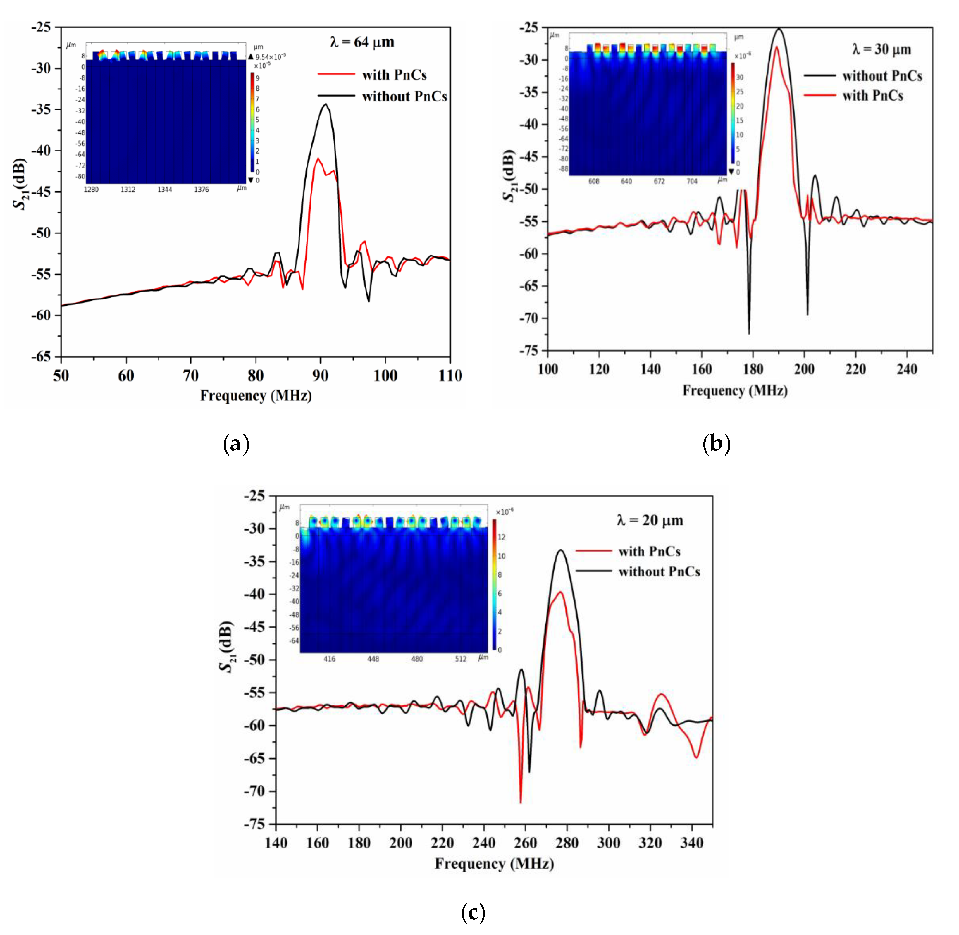
We now turn to the interaction of the SAW generated by the interdigital transducers (IDTs) with the phononic crystal made of parallel ridges. Figure 13 shows the scattering parameters S21 of the Al/ScxAl1-xN/Sapphire for x = 37.5%, obtained with and without the phononic crystal at different wavelengths. The wavelengths were chosen in order to track the frequencies’ eigenmodes of the ridges, namely A′, C′, and D′. To define the appropriated wavelengths, we used the expression f = vsaw, where the surface wave velocity results from the calculation at x = 37.5%. We found that the wavelengths λ = 64 μm, λ = 30 μm, and λ = 20 μm cover respectively the eigenfrequencies A′, C′, and D′.
In all cases, it is seen in Figure 13 that the electrical performances of S21 are affected in the vicinity of the SAW central frequency. In other words, the propagation of the SAW is disturbed by the presence of the ridged structure, resulting in a decrease in the mechanical energy of the IDT receiver. S21 also presents a slight frequency shift toward low frequencies because of the mass loading effect caused by the presence of the PnC [87,88]. S21 in the delay line also shows small oscillations, which are induced by Fabry–Perot reflection from the metallic IDT fingers [89].
Finally, using the values of the elastic constants Cij (Figure 4a), and the piezoelectric eij (Figure 4b) and dielectric values ɛij (Figure 4c), the dependence of the insertion loss (S21) of the SAW delay line without PnCs versus the c-axis tilted angle (θ°) of Sc0.375Al0.625N was examined for θ = 20°, 40°, 60° and 80°, and compared to that when the c-axis is normally oriented (θ = 0°). The result is reported in Figure 14a, which shows that the insertion loss (S21) is affected by the c-axis tilting. The variation in the insertion loss is directly linked to the electromechanical coupling coefficient, which is very sensitive to the tilted angle [90].
Figure 14b shows that the minimum value of insertion loss is found at the tilting angle θ = 60°. This is due to the coupling factor, whose value is maximum at this angle, which also in good concordance with experimental data [33]. This maximum coupling factor is due to the large piezoelectric constant e15 and e31 of Sc0.375Al0.625N thin films (see Figure 4b). In addition, the variation om the resonances frequencies as a function of x behaves as the calculated SAW velocities at λ= 20 µm (5531.4, 5473.2, 5495.6, 5466.4, and 5405 m/s).
In summary, we observed a significant improvement in the insertion loss at the 60° inclined Sc0.375Al0.625N SAW delay line compared to the pure AlN SAW delay line. The same improvement was observed experimentally by A. Kochar et al. [26,30]. Moreover, the passing frequency band of the SAW delay line based on 60° inclined pure AlN is shifted down to the low frequencies compared to Sc0.375Al0.625N at the same angle. This is due to the influence of the Sc concentration on the acoustic velocity [91].

4. Conclusions

In this work, the effects of Sc concentrations on electro-acoustic material properties were theoretically investigated for w-ScxAl1-xN in the x range from 0 to 37.5% by means of Density Functional Theory. The calculated elastic, piezoelectric, and dielectric properties using the GGA-PBE function show very good agreement with experiments and theoretical works. For all considered Sc contents, w-ScxAl1-xN material exhibits good mechanical stability criteria. By increasing the Sc concentrations for pure AlN, the elastic constants C11 and C33 decrease, whereas the piezoelectric (e33) and dielectric (ε33) constants increase, enhancing the performance of the SAW devices based on w-Sc0.375Al0.625N.
Furthermore, the dependences of the electro-acoustic properties (Cij, eij, and εij) with the tilted angle of w-Sc0.375Al0.625N was investigated. It is observed that all these properties exhibit a symmetric behavior at a 0° tilted angle, whereas an opposite trend for both C11, C33, ε11, and ε33 was found at the tilted angle of 45°. The material becomes non-piezoelectric at the tilted angle of 90°.
The electro-acoustic properties of w-Sc0.375Al0.625N calculated by DFT were used to calculate the dispersion curves of a pillared phononic crystal deposited on top of the substrate. The effects of scandium (Sc) concentration and tilted angle θ° of w-Sc0.375Al0.625N on acoustic band gaps and S21 scattering parameters were studied for the first time. The geometrical, (h = 6 μm and r = 2.6 µm), and physical (x = 37.5%) parameters were found to be the appropriate choice to obtain a maximum bandwidth of 44.83 MHz. By comparison, a symmetric behavior at a 0° tilted angle was also revealed for larger acoustic band gaps. An improvement in the S21 intensity (in dB) of SAW delay lines is demonstrated when x = 37.5% for a normally oriented c-axis. We found that 60° is an optimal tilted angle to improve the insertion loss (S21) from −19 dB for AlN to −12.8 dB for w-Sc0.375Al0.625N. Ongoing work is dealing with AlScN-SAW devices coupled with 2D phononic crystal as a highly sensitive micro-sensor for liquid property determination.

Supplementary Materials

The following supporting information can be downloaded at: https://www.mdpi.com/article/10.3390/cryst12101431/s1. The figure S1 describes the evolution of the acoustic bandgap (gap map) as a function of the aspect ratio (r/a). The figure S2 represents the evolution of the center’s frequency fc and the widths Bw of the first and second bandgap as a function of r. The figure S3 shows the dispersion curves, the transmission spectrum and displacement field of modes A’, B’, and C’.

Author Contributions

Conceptualization, F.A., F.K. and R.S.; methodology, F.A., F.K. and Y.P.; formal analysis, F.A., Z.Ö. and K.B.; writing—original draft preparation, F.A.; supervision, Y.P. All authors have read and agreed to the published version of the manuscript.

Funding

This research received no external funding.

Institutional Review Board Statement

Not applicable.

Informed Consent Statement

Not applicable.

Data Availability Statement

Data are available upon request to the corresponding authors.

Acknowledgments

This work was supported by the General Directorate of Scientific Research and Technological Development DGRSDT of Algeria. The High-Performance Computing Network of the University of Setif 1 is acknowledged for computer time.

Conflicts of Interest

The authors declare no conflict of interest.

References

  1. Panneerselvam, G.; Thirumal, V.; Pandya, H.M. Review of surface acoustic wave sensors for the detection and identification of toxic environmental Gases/Vapours. Arch. Acoust. 2019, 44, 117–127. [Google Scholar]
  2. Caliendo, C.; Imperatori, P. High-frequency, high-sensitivity acoustic sensor implemented on ALN/Si substrate. Appl. Phys. Lett. 2003, 83, 1641–1643. [Google Scholar] [CrossRef]
  3. Korovin, A.V.; Pennec, Y.; Stocchi, M.; Mencarelli, D.; Pierantoni, L.; Makkonen, T.; Ahopelto, J.; Rouhani, B.D. Conversion between surface acoustic waves and guided modes of a quasi-periodic structured nanobeam. J. Phys. D Appl. Phys. 2019, 52, 32LT01. [Google Scholar] [CrossRef]
  4. Water, W.; Yan, Y.-S.; Meen, T.-H. Effect of magnesium doping on the structural and piezoelectric properties of sputtered ZnO thin film. Sens. Actuators A: Phys. 2008, 144, 105–108. [Google Scholar] [CrossRef]
  5. Toyama, M.; Kubo, R.; Takata, E.; Tanaka, K.; Ohwada, K. Characterization of piezoelectric properties of PZT thin films deposited on Si by ECR sputtering. Sens. Actuators A: Phys. 1994, 45, 125–129. [Google Scholar] [CrossRef]
  6. Lin, C.-M.; Chen, Y.-Y.; Felmetsger, V.V.; Lien, W.-C.; Riekkinen, T.; Senesky, D.; Pisano, A.P. Surface acoustic wave devices on AlN/3C–SiC/Si multilayer structures. J. Micromech. Microeng. 2013, 23, 25019. [Google Scholar] [CrossRef]
  7. Deger, C.; Born, E.; Angerer, H.; Ambacher, O.; Stutzmann, M.; Hornsteiner, J.; Riha, E.; Fischerauer, G. Sound velocity of AlxGa1−xN thin films obtained by surface acoustic-wave measurements. Appl. Phys. Lett. 1998, 72, 2400–2402. [Google Scholar] [CrossRef]
  8. Doll, J.C.; Petzold, B.C.; Ninan, B.; Mullapudi, R.; Pruitt, B.L. Aluminum nitride on titanium for CMOS compatible piezoelectric transducers. J. Micromechanics Microengineering 2009, 20, 25008. [Google Scholar] [CrossRef] [Green Version]
  9. Kurz, N.; Ding, A.; Urban, D.F.; Lu, Y.; Kirste, L.; Feil, N.M.; Žukauskaitė, A.; Ambacher, O. Experimental determination of the electro-acoustic properties of thin film AlScN using surface acoustic wave resonators. J. Appl. Phys. 2019, 126, 075106. [Google Scholar] [CrossRef]
  10. Mayrhofer, P.; Riedl, H.; Euchner, H.; Stöger-Pollach, M.; Bittner, A.; Schmid, U. Microstructure and piezoelectric response of Y Al1−N thin films. Acta Mater. 2015, 100, 81–89. [Google Scholar] [CrossRef] [Green Version]
  11. Yanagitani, T.; Jia, J. ScAlN polarization inverted resonators and enhancement of kt 2 in new YbAlN materials for BAW devices. In Proceedings of the IEEE International Ultrasonics Symposium (IUS); 2019; pp. 894–899. [Google Scholar] [CrossRef]
  12. Assali, A.; Laidoudi, F.; Serhane, R.; Kanouni, F.; Mezilet, O. Highly Enhanced Electro-acoustic Properties of YAlN/Sapphire Based Surface Acoustic Wave Devices for Next Generation of Microelectromechanical Systems. Mater. Today Commun. 2021, 26, 102067. [Google Scholar] [CrossRef]
  13. Laidoudi, F.; Amara, S.; Caliendo, C.; Boubenider, F.; Kanouni, F.; Assali, A. High quality and low loss surface acoustic wave SAW resonator based on chromium-doped AlN on sapphire. Appl. Phys. A 2021, 127, 1–11. [Google Scholar] [CrossRef]
  14. Amara, S.; Kanouni, F.; Laidoudi, F.; Bouamama, K. Low loss surface acoustic wave SAW devices based on Al1-xMxN (M=Cr, Y, Sc) thin films. Phys. B: Condens. Matter 2021, 615, 412990. [Google Scholar] [CrossRef]
  15. Fei, C.; Liu, X.; Zhu, B.; Li, D.; Yang, X.; Yang, Y.; Zhou, Q. AlN piezoelectric thin films for energy harvesting and acoustic devices. Nano Energy 2018, 51, 146–161. [Google Scholar] [CrossRef]
  16. Aubert, T.; Naumenko, N.; Bartoli, F.; Pigeat, P.; Streque, J.; Ghanbaja, J.; Elmazria, O. Non-leaky longitudinal acoustic modes in ScxAl1-xN/sapphire structure for high-temperature sensor applications. Appl. Phys. Lett. 2019, 115, 83502. [Google Scholar] [CrossRef]
  17. Qi, W.; Lu, Y.; Fung, S.; Jiang, X.; Horsley, D. Scandium Doped Aluminum Nitride Based Piezoelectric Micromachined Ultrasound Transducers. In Proceedings of the Hilton Head Workshop 2016: A Solid-State Sensors, Actuators and Microsystems Workshop, Hilton Head, SC, USA, 5–9 June 2016. [Google Scholar]
  18. Casamento, J.; Chang, C.S.; Shao, Y.-T.; Wright, J.; Muller, D.A.; Xing, H.; Jena, D. Structural and piezoelectric properties of ultra-thin ScxAl1−xN films grown on GaN by molecular beam epitaxy. Appl. Phys. Lett. 2020, 117, 112101. [Google Scholar] [CrossRef]
  19. Akiyama, M.; Kamohara, T.; Kano, K.; Teshigahara, A.; Takeuchi, Y.; Kawahara, N. Enhancement of Piezoelectric Response in Scandium Aluminum Nitride Alloy Thin Films Prepared by Dual Reactive Cosputtering. Adv. Mater. 2008, 21, 593–596. [Google Scholar] [CrossRef]
  20. Akiyama, M.; Kano, K.; Teshigahara, A. Influence of growth temperature and scandium concentration on piezoelectric response of scandium aluminum nitride alloy thin films. Appl. Phys. Lett. 2009, 95, 162107. [Google Scholar] [CrossRef]
  21. Wingqvist, G.; Tasnadi, F.; Zukauskaite, A.; Birch, J.; Arwin, H.; Hultman, L. Increased electromechanical coupling in w−ScxAl1−xN. Appl. Phys. Lett. 2010, 97, 112902. [Google Scholar] [CrossRef]
  22. Konno, A.; Sumisaka, M.; Teshigahara, A.; Kano, K.; Hashimo, K.-Y.; Hirano, H.; Esashi, M.; Kadota, M.; Tanaka, S.; Konno, A.; et al. ScAlN Lamb wave resonator in GHz range released by XeF2 etching. In Proceedings of the 2013 IEEE International Ultrasonics Symposium (IUS), Prague, Czech Republic, 21–25 July 2013; 2013; pp. 1378–1381. [Google Scholar] [CrossRef]
  23. Wang, W.; Mayrhofer, P.M.; He, X.; Gillinger, M.; Ye, Z.; Wang, X.; Bittner, A.; Schmid, U.; Luo, J. High performance AlScN thin film based surface acoustic wave devices with large electromechanical coupling coefficient. Appl. Phys. Lett. 2014, 105, 133502. [Google Scholar] [CrossRef]
  24. Teshigahara, A.; Hashimoto, K.-Y.; Akiyama, M. Scandium aluminum nitride: Highly piezoelectric thin film for RF SAW devices in multi GHz range. In Proceedings of the IEEE International Ultrasonics Symposium, Dresden, Germany, 7–10 October 2012; pp. 1–5. [Google Scholar] [CrossRef]
  25. Wu, S.; Wu, M.Y.; Huang, J.-L.; Lii, D.-F. Characterization and Piezoelectric Properties of Reactively Sputtered (Sc, Al)N Thin Films on Diamond Structure. Int. J. Appl. Ceram. Technol. 2013, 11, 894–900. [Google Scholar] [CrossRef]
  26. Kochhar, A.; Yamamoto, Y.; Teshigahara, A.; Hashimoto, K.-Y.; Tanaka, S.; Esashi, M. Wave Propagation Direction and c-Axis Tilt Angle Influence on the Performance of ScAlN/Sapphire-Based SAW Devices. IEEE Trans. Ultrason. Ferroelectr. Freq. Control 2016, 63, 953–960. [Google Scholar] [CrossRef]
  27. Gillinger, M.; Shaposhnikov, K.; Knobloch, T.; Schneider, M.; Kaltenbacher, M.; Schmid, U. Impact of layer and substrate properties on the surface acoustic wave velocity in scandium doped aluminum nitride based SAW devices on sapphire. Appl. Phys. Lett. 2016, 108, 231601. [Google Scholar] [CrossRef]
  28. Kanouni, F.; Amara, S.; Assali, A.; Arab, F.; Qin, Z. A P-matrix-based model for the frequency analysis of IDT/AlScN/Sapphire SAW-delay line. Sens. Actuators A Phys. 2020, 307, 111980. [Google Scholar] [CrossRef]
  29. Gillinger, M.; Knobloch, T.; Schneider, M.; Schmid, U. Harsh Environmental Surface Acoustic Wave Temperature Sensor Based on Pure and Scandium doped Aluminum Nitride on Sapphire. Multidiscip. Digit. Publ. Inst. Proc. 2017, 1, 341. [Google Scholar] [CrossRef] [Green Version]
  30. Bartoli, F.; Moutaouekkil, M.; Streque, J.; Pigeat, P.; Hage-Ali, S.; Boulet, P.; M’Jahed, H.; Elmazria, O.; Zhgoon, S.; Aubert, T.; et al. Theoretical and experimental study of ScAlN/Sapphire structure based SAW sensor. IEEE Sens. 2017, 1–3. [Google Scholar] [CrossRef] [Green Version]
  31. Kochhar, A.; Yamamoto, Y.; Teshigahara, A.; Hashimoto, K.-Y.; Tanaka, S.; Esashi, M. NSPUDT using c-axis tilted ScAlN thin film. In Proceedings of the Joint Conference of the IEEE International Frequency Control Symposium & the European Frequency and Time Forum, Orlando, FL, USA, 14–18 April 2015; pp. 633–636. [Google Scholar] [CrossRef]
  32. Tokuda, S.; Takayanagi, S.; Matsukawa, M.; Yanagitani, T. Film growth of c-axis tilted ScAlN on the sapphire substrate for SAW devices. In Proceedings of the 2017 IEEE International Ultrasonics Symposium (IUS), Washington, DC, USA, 6–9 September 2017; pp. 1–4. [Google Scholar] [CrossRef]
  33. Tominaga, T.; Takayanagi, S.; Yanagitani, T. c-axis-tilted ScAlN film on silicon substrate for surface acoustic wave device. In Proceedings of the 2021 IEEE International Ultrasonics Symposium (IUS), Xi’an, China, 11–16 September 2021; pp. 1–4. [Google Scholar] [CrossRef]
  34. Tominaga, T.; Takayanagi, S.; Yanagitani, T. c-Axis-tilted ScAlN films grown on silicon substrates for surface acoustic wave devices. Jpn. J. Appl. Phys. 2022, 61, SG1054. [Google Scholar] [CrossRef]
  35. Djafari-Rouhani, B.; Maradudin, A.A.; Wallis, R.F. Rayleigh waves on a superlattice stratified normal to the surface. Phys. Rev. B 1984, 29, 6454–6462. [Google Scholar] [CrossRef]
  36. Tanaka, Y.; Tamura, S.-I. Surface acoustic waves in two-dimensional periodic elastic structures. Phys. Rev. B 1998, 58, 7958–7965. [Google Scholar] [CrossRef] [Green Version]
  37. Wu, T.-T.; Wu, L.-C.; Huang, Z.-G. Frequency band-gap measurement of two-dimensional air/silicon phononic crystals using layered slanted finger interdigital transducers. J. Appl. Phys. 2005, 97, 094916. [Google Scholar] [CrossRef]
  38. Hsu, J.-C.; Lin, Y.-D. Microparticle concentration and separation inside a droplet using phononic-crystal scattered standing surface acoustic waves. Sens. Actuators A Phys. 2019, 300, 111651. [Google Scholar] [CrossRef]
  39. Benchabane, S.; Khelif, A.; Rauch, J.-Y.; Robert, L.; Laude, V. Evidence for complete surface wave band gap in a piezoelectric phononic crystal. Phys. Rev. E 2006, 73, 65601. [Google Scholar] [CrossRef] [Green Version]
  40. Yudistira, D.; Pennec, Y.; Rouhani, B.D.; Dupont, S.; Laude, V. Non-radiative complete surface acoustic wave bandgap for finite-depth holey phononic crystal in lithium niobate. Appl. Phys. Lett. 2012, 100, 61912. [Google Scholar] [CrossRef] [Green Version]
  41. White, R.M.; Voltmer, F.W. Direct piezoelectric Coupling to surface elastic waves. Appl. Phys. Lett. 1965, 7, 314–316. [Google Scholar] [CrossRef]
  42. Sigalas, M.; Economou, E. Elastic and acoustic wave band structure. J. Sound Vib. 1992, 158, 377–382. [Google Scholar] [CrossRef]
  43. Li, G.; Ma, F.; Guo, J.; Zhao, H. Case Study of Roadway Deformation Failure Mechanisms: Field Investigation and Numerical Simulation. Energies 2021, 14, 1032. [Google Scholar] [CrossRef]
  44. Mohammadi, S.; Adibi, A. On chip complex signal processing devices using coupled phononic crystal slab resonators and waveguides. AIP Adv. 2011, 1, 41903. [Google Scholar] [CrossRef]
  45. Wu, T.; Sun, J. 4G-3 guided surface acoustic waves in phononic crystal waveguides. In Proceedings of the 2006 IEEE Ultrasonics Symposium 2006, Vancouver, BC, Canada, 3–6 October 2006; pp. 673–676. [Google Scholar]
  46. Salman, A.; Kaya, O.A.; Cicek, A. Determination of concentration of ethanol in water by a linear waveguide in a 2-dimensional phononic crystal slab. Sens. Actuators A Phys. 2014, 208, 50–55. [Google Scholar] [CrossRef]
  47. Wu, T.; Wang, W.; Sun, J. A layered SAW device using phononic-crystal reflective gratings. In Proceedings of the 2008 IEEE Ultrasonics Symposium, Beijing, China, 2–5 November 2008; pp. 709–712. [Google Scholar]
  48. Imanian, H.; Noori, M.; Abbasiyan, A. Highly efficient gas sensor based on quasi-periodic phononic crystals. Sens. Actuators B Chem. 2021, 345, 130418. [Google Scholar] [CrossRef]
  49. Ramakrishnan, N.; Palathinkal, R.P.; Nemade, H.B. Mass Loading Effect of High Aspect Ratio Structures Grown Over Surface Acoustic Wave Resonators. Sens. Lett. 2010, 8, 253–257. [Google Scholar] [CrossRef]
  50. Benchabane, S.; Gaiffe, O.; Ulliac, G.; Salut, R.; Achaoui, Y.; Laude, V. Observation of surface-guided waves in holey hypersonic phononic crystal. Appl. Phys. Lett. 2011, 98, 171908. [Google Scholar] [CrossRef]
  51. Yankin, S.; Talbi, A.; Du, Y.; Gerbedoen, J.-C.; Preobrazhensky, V.; Pernod, P.; Matar, O.B. Finite element analysis and experimental study of surface acoustic wave propagation through two-dimensional pillar-based surface phononic crystal. J. Appl. Phys. 2014, 115, 244508. [Google Scholar] [CrossRef]
  52. Binci, L.; Tu, C.; Zhu, H.; Lee, J.E.-Y. Planar ring-shaped phononic crystal anchoring boundaries for enhancing the quality factor of Lamb mode resonators. Appl. Phys. Lett. 2016, 109, 203501. [Google Scholar] [CrossRef]
  53. Ardito, R.; Cremonesi, M.; D’Alessandro, L.; Frangi, A. Application of optimally-shaped phononic crystals to reduce anchor losses of MEMS resonators. In Proceedings of the IEEE International Ultrasonics Symposium (IUS), Montreal, QC, Canada, 5–8 September 2016; pp. 1–3. [Google Scholar] [CrossRef] [Green Version]
  54. Siddiqi, M.W.U.; Lee, J.E.-Y. Quality factor enhancement of AlN-on-Si lamb wave resonators using a hybrid of phononic crystal shapes in anchoring boundaries. In Proceeding of the 20th International Conference on Solid-State Sensors, Actuators and Microsystems &Eurosensors XXXIII (Transducers & Eurosensors XXXIII), Berlin, Germany, 23–27 June 2019; pp. 913–916. [Google Scholar] [CrossRef]
  55. Tong, Y.; Han, T. Anchor Loss Reduction of Lamb Wave Resonator by Pillar-Based Phononic Crystal. Micromachines 2021, 12, 62. [Google Scholar] [CrossRef]
  56. Pourabolghasem, R.; Dehghannasiri, R.; Eftekhar, A.A.; Adibi, A. Waveguiding Effect in the Gigahertz Frequency Range in Pillar-based Phononic-Crystal Slabs. Phys. Rev. Appl. 2018, 9, 14013. [Google Scholar] [CrossRef] [Green Version]
  57. Dehghannasiri, R.; Eftekhar, A.A.; Adibi, A. Hypersonic Surface Phononic Bandgap Demonstration in a CMOS-Compatible Pillar-Based Piezoelectric Structure on Silicon. Phys. Rev. Appl. 2018, 10, 64019. [Google Scholar] [CrossRef]
  58. Taleb, F.; Darbari, S. Tunable Locally Resonant Surface-Acoustic-Waveguiding Behavior by Acoustoelectric Interaction in ZnO -Based Phononic Crystal. Phys. Rev. Appl. 2019, 11, 24030. [Google Scholar] [CrossRef]
  59. Perdew, J.P.; Burke, K.; Ernzerhof, M. Generalized gradient approximation made simple. Phys. Rev. Lett. 1996, 77, 3865. [Google Scholar] [CrossRef] [Green Version]
  60. Monkhorst, H.J.; Pack, J.D. Special points for Brillouin-zone integrations. Phys. Rev. B 1976, 13, 5188. [Google Scholar] [CrossRef]
  61. Baroni, S.; Giannozzi, P.; Testa, A. Green’s-function approach to linear response in solids. Phys. Rev. Lett. 1987, 58, 1861–1864. [Google Scholar] [CrossRef]
  62. COMSOL Multiphysics. Available online: https://www.comsol.com/ (accessed on 10 September 2022).
  63. Schulz, H.; Thiemann, K. Crystal structure refinement of AlN and GaN. Solid State Commun. 1977, 23, 815–819. [Google Scholar] [CrossRef]
  64. Momida, H.; Teshigahara, A.; Oguchi, T. Strong enhancement of piezoelectric constants in ScxAl1−xN: First-principles calculations. AIP Adv. 2016, 6, 65006. [Google Scholar] [CrossRef] [Green Version]
  65. Urban, D.F.; Ambacher, O.; Elsässer, C. First-principles calculation of electroacoustic properties of wurtzite (Al,Sc)N. Phys. Rev. B 2021, 103, 115204. [Google Scholar] [CrossRef]
  66. Ambacher, O.; Christian, B.; Feil, N.; Urban, D.F.; Elsässer, C.; Prescher, M.; Kirste, L. Wurtzite ScAlN, InAlN, and GaAlN crystals, a comparison of structural, elastic, dielectric, and piezoelectric properties. J. Appl. Phys. 2021, 130, 45102. [Google Scholar] [CrossRef]
  67. Caro, M.A.; Zhang, S.; Riekkinen, T.; Ylilammi, M.; Moram, M.A.; Lopez-Acevedo, O.; Molarius, J.; Laurila, T. Piezoelectric coefficients and spontaneous polarization of ScAlN. J. Physics Condens. Matter 2015, 27, 245901. [Google Scholar] [CrossRef] [Green Version]
  68. Tsubouchi, K.; Sugai, K.; Mikoshiba, N. AlN material constants evaluation and SAW properties on AlN/Al2O3 and AlN/Si. In Proceedings of the 1981 Ultrasonics Symposium, Chicago, IL, USA, 14–16 October 1981; pp. 375–380. [Google Scholar]
  69. Sotnikov, A.V.; Schmidt, H.; Weihnacht, M.; Smirnova, E.P.; Chemekova, T.Y.; Makarov, Y.N. Elastic and piezoelectric properties of AlN and LiAlO2 single crystals. IEEE Trans. Ultrason. Ferroelectr. Freq. Control 2010, 57, 808–811. [Google Scholar] [CrossRef]
  70. Kim, T.; Kim, J.; Dalmau, R.; Schlesser, R.; Preble, E.; Jiang, X. High-temperature electromechanical characterization of AlN single crystals. IEEE Trans. Ultrason. Ferroelectr. Freq. Control 2015, 62, 1880–1887. [Google Scholar] [CrossRef]
  71. Kazan, M.; Moussaed, E.; Nader, R.; Masri, P. Elastic constants of aluminum nitride. Phys. Status Solidi 2007, 4, 204–207. [Google Scholar] [CrossRef]
  72. Watt, J.P.; Peselnick, L. Clarification of the Hashin-Shtrikman bounds on the effective elastic moduli of polycrystals with hexagonal, trigonal, and tetragonal symmetries. J. Appl. Phys. 1980, 51, 1525–1531. [Google Scholar] [CrossRef]
  73. Mayrhofer, P.; Euchner, H.; Bittner, A.; Schmid, U. Circular test structure for the determination of piezoelectric constants of Scx Al1−xN thin films applying Laser Doppler Vibrometry and FEM simulations. Sens. Actuators A Phys. 2014, 222, 301–308. [Google Scholar] [CrossRef] [Green Version]
  74. Manna, S.; Talley, K.R.; Gorai, P.; Mangum, J.; Zakutayev, A.; Brennecka, G.L.; Stevanović, V.; Ciobanu, C.V. Enhanced Piezoelectric Response of AlN via CrN Alloying. Phys. Rev. Appl. 2018, 9, 034026. [Google Scholar] [CrossRef] [Green Version]
  75. Nye, J.F. Physical Properties of Crystals: Their Representation by Tensors and Matrices; Oxford University Press: Oxford, UK, 1985. [Google Scholar]
  76. Qin, L.; Chen, Q.; Cheng, H.; Wang, Q.-M. Analytical study of dual-mode thin film bulk acoustic resonators (FBARs) based on ZnO and AlN films with tilted c-axis orientation. IEEE Trans. Ultrason. Ferroelectr. Freq. Control 2010, 57, 1840–1853. [Google Scholar] [CrossRef]
  77. Newnham, R.E. Properties of Materials: Anisotropy, Symmetry, Structure; Oxford University Press: Oxford, UK, 2005. [Google Scholar]
  78. Kong, L.; Zhang, J.; Wang, H.; Ma, S.; Li, F.; Wang, Q.-M.; Qin, L. Simulation study of MEMS piezoelectric vibration energy harvester based on c-axis tilted AlN thin film for performance improvement. AIP Adv. 2016, 6, 125128. [Google Scholar] [CrossRef]
  79. Qin, L.; Wang, Q.-M. Analysis of dual-mode thin film bulk acoustic resonators based on polar c-axis tilted wurtzite gallium nitride. J. Appl. Phys. 2010, 107, 114102. [Google Scholar] [CrossRef]
  80. Xie, M.-Y.; Tasnádi, F.; Abrikosov, I.A.; Hultman, L.; Darakchieva, V. Elastic constants, composition, and piezolectric polarization in InxAl1−xN: From ab initio calculations to experimental implications for the applicability of Vegard’s rule. Phys. Rev. B 2012, 86, 155310. [Google Scholar] [CrossRef] [Green Version]
  81. Benchabane, S.; Gaiffe, O.; Salut, R.; Ulliac, G.; Laude, V.; Kokkonen, K. Guidance of surface waves in a micron-scale phononic crystal line-defect waveguide. Appl. Phys. Lett. 2015, 106, 81903. [Google Scholar] [CrossRef] [Green Version]
  82. Wu, T.-C.; Wu, T.-T.; Hsu, J.-C. Waveguiding and frequency selection of Lamb waves in a plate with a periodic stubbed surface. Phys. Rev. B 2009, 79, 104306. [Google Scholar] [CrossRef]
  83. Pennec, Y.; Laude, V.; Papanikolaou, N.; Djafari-Rouhani, B.; Oudich, M.; El Jallal, S.; Beugnot, J.-C.; Escalante, J.M.; Martínez, A. Modeling light-sound interaction in nanoscale cavities and waveguides. Nanophotonics 2014, 3, 413–440. [Google Scholar] [CrossRef] [Green Version]
  84. Addouche, M.; Al-Lethawe, M.A.; Choujaa, A.; Khelif, A. Superlensing effect for surface acoustic waves in a pillar-based phononic crystal with negative refractive index. Appl. Phys. Lett. 2014, 105, 023501. [Google Scholar] [CrossRef]
  85. Oudich, M.; Li, Y.; Assouar, B.; Hou, Z. A sonic band gap based on the locally resonant phononic plates with stubs. New J. Phys. 2010, 12. [Google Scholar] [CrossRef]
  86. Achaoui, Y.; Khelif, A.; Benchabane, S.; Robert, L.; Laude, V. Experimental observation of locally-resonant and Bragg band gaps for surface guided waves in a phononic crystal of pillars. Phys. Rev. B 2011, 83. [Google Scholar] [CrossRef] [Green Version]
  87. Tian, Y.; Li, H.; Chen, W.; Lu, Z.; Luo, W.; Mu, X.; Wang, L. A Novel Love Wave Mode Sensor Waveguide Layer with Microphononic Crystals. Appl. Sci. 2021, 11, 8123. [Google Scholar] [CrossRef]
  88. Serhane, R.; Belkhelfa, N.; Hadj-Larbi, F.; Merah, S.; Bakha, Y. Electrical Performances of a Surface Acoustic Wave Device With Inter Digital Transducers Electrodes in Local Resonances. J. Vib. Acoust. AMSE 2021, 143, 011009 [CrossRef]. [Google Scholar] [CrossRef]
  89. Shao, L.; Maity, S.; Zheng, L.; Wu, L.; Shams-Ansari, A.; Sohn, Y.-I.; Puma, E.; Gadalla, M.; Zhang, M.; Wang, C.; et al. Phononic Band Structure Engineering for High- Q Gigahertz Surface Acoustic Wave Resonators on Lithium Niobate. Phys. Rev. Appl. 2019, 12, 14022. [Google Scholar] [CrossRef] [Green Version]
  90. Laidoudi, F.; Boubenider, F.; Caliendo, C.; Hamidullah, M. Numerical Investigation of Rayleigh, Sezawa and Love Modes in C-Axis Tilted ZNO/SI for Gas and Liquid Multimode Sensor. J. Mech. 2019, 36, 7–18. [Google Scholar] [CrossRef]
  91. Caliendo, C.; Hamidullah, M.; Mattioli, F. Finite Element Modeling and Synthesis of c-axis Tilted AlN TFBAR for Liquid Sensing Applications. Procedia Eng. 2016, 168, 1032–1035. [Google Scholar] [CrossRef]
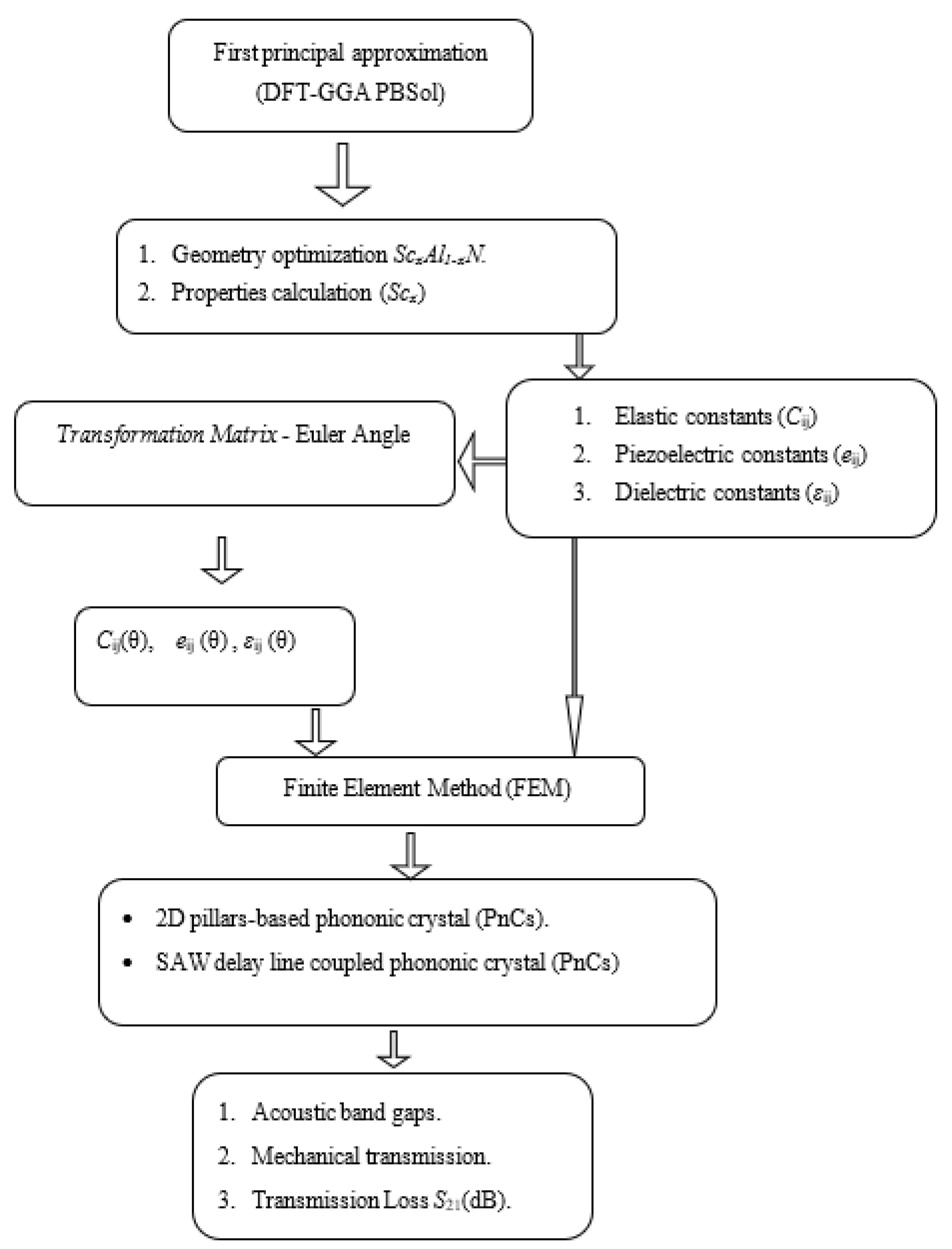
Figure 1. Diagram of the calculation methodology.
Crystals 12 01431 g001
Figure 2. Comparison between (a) our calculated elastic constants Cij (GPa), and (b) piezoelectric coefficients eij (C/m2), with data available from the literature.
Crystals 12 01431 g002
Figure 3. Calculated dielectric constants ε11 and ε33 as a function of Sc concentration for w-ScxAl1-xN.
Crystals 12 01431 g003
Figure 4. (a) Elastic constants, (b) piezoelectric coefficient, and (c) dielectric constants in (10−11 F/m) of tilted w-Sc0.375Al0.625N.
Crystals 12 01431 g004aCrystals 12 01431 g004b
Figure 5. (a) PnC unit cell used for the dispersion curve calculation. (b) First irreducible Brillouin zone.
Crystals 12 01431 g005
Figure 6. Acoustic band structure of PnC AlN pillars with r = 3 µm, and h = 2.4 µm. The blue hatched area corresponds to the position of the acoustic band gap.
Crystals 12 01431 g006
Figure 7. PnC band structures of lattice parameter a = 8 µm for AlN pillars of radius r = 3 µm and different values of h: (a) h = 4 µm, (b) h = 6 µm and (c) h = 8 µm.
Crystals 12 01431 g007aCrystals 12 01431 g007b
Figure 8. (a) Evolution of the acoustic bandgaps (gaps map) as a function of the aspect ratio (h/a). (b) Evolution of the center frequency fc and the bandgap width Bw of the first and second bandgaps as a function of the height of the pillars of radius r = 2.6 µm.
Crystals 12 01431 g008aCrystals 12 01431 g008b
Figure 9. Evolution of (a) the bandgaps map, and (b) the center frequency fc and bandgap width Bw of the first and second bandgaps with Sc concentration (x).
Crystals 12 01431 g009
Figure 10. Evolution of (a) the bandgaps map, and (b) the center frequencies fc and bandgap widths Bw of the first and second bandgaps with the angle θ of tilted w-Sc0.375Al0.625N based PnCs structure.
Crystals 12 01431 g010
Figure 11. (a) Acoustic band structures of PnC w-Sc0.375Al0.625N pillars on half infinite substrate. (b) Transmission through a finite PnC constituted of an 11-unit cell, with h = 6 µm, r = 2.6 µm, and a = 8 µm (red solid line) compared to the SAW through a non-structured surface (dashed lines). (c) Map of the mechanical displacement fields of modes (A, B, C, D, and E).
Crystals 12 01431 g011
Figure 12. (a) 2D model used for the calculation of the transmission using the IDT. The PnC was set between the input and output IDTs. (b) Insertion loss (S21) for different values of Sc concentration x of the non-structured surface.
Crystals 12 01431 g012
Figure 13. Insertion loss (S21) with (red solid lines) and without (black solid lines) PnCs for different SAW device wavelengths, (a) λ = 64 µm, (b) λ = 30 µm, and (c) λ = 20 µm closed to the eigenmodes A, C, and D.
Crystals 12 01431 g013
Figure 14. (a) Insertion loss (S21) of the SAW delay line without PnCs of w-Sc0.375Al0.625N. (b) Insertion loss (S21) and frequency of SAW delay line without PnCs versus the c-axis tilted angle (θ°) of w-Sc0.375Al0.625N.
Crystals 12 01431 g014
Table 1. Comparison of equilibrium lattice parameters (a, c) (Å) and elastic constants Cij (GPa) for w-ScxAl1-xN compound (x = 0%, 12.5%, 25% and 37.5%) between our results (*) and the literature.
Material
Constants
w-AlNw-ScxAl1-xN
Th.Exp.x12.5%25%37.5%
a (Å)3.128 * 3.1163 3.1842*3.2426 *3.3136 *
3.13164
c (Å)5.015 *4.9863 5.0489*5.0696 *5.065*
5.01864
C11 (GPa)376 * 402.5 ± 0.569 332.91 *302.56282.64 *
43264 37465412.6 ± 0.0570336.3765305.6865282.03665
378.867 34568394 71
C12 (GPa)123 * 135.6 ± 0.569 126.86 *130.82 *121.45 *
17064 12965126.6 ± 0.570
128.967 12568134 71121.9565116.0365110.4465
C13 (GPa)91*101 ± 269 104.84104.86 *112.06 *
14764 10165118.8 ± 0.97091.116583.436577.2565
96.167 120689571
C33 (GPa)354* 387.6 ± 169 293.99 *251.91*220.94 *
39064 35165386.1 ± 4.570302.1165255.3365211.3765
357.567 3956840271
C44 (GPa)116*122.9 ± 0.569 103.47 *96.09*87.29 *
15564 11265 127.4 ± 0.970102.156597.4896597.5965
11267 1186812171
*: Our calculations.
Table 2. Comparison of calculated piezoelectric (e15, e31, e33) and dielectric constants (ε11, ε33) for w-ScxAl1-xN compound between our results (*) and the literature.
Material
Coefficient
w-AlNw-ScxAl1-xN
Th.Exp.x12.5%25%37.5%
e31 (C/m2)−0.58 *−0.54 ± 0.059 −0.624 *−0.660 *−0.686 *
−0.5564–0.59365−0.6 ± 0.269−0.62565−0.67565−0.74365
–0.42467–0.5868−0.47 ± 0.270
e33 (C/m2)1.45 *1.52 ± 0.439 1.705 *2.026 *2.421 *
1.3964 1.471651.34 ± 0.1691.70652.142652.78865
1.44967 1.55682.09 ± 0.470
e15 (C/m2)−0.29 *−0.30 ± 0.229 −0.311*−0.306 *−0.282 *
−0.3064–0.31365−0.32 ± 0.0569−0.29365−0.25665−0.20465
–0.36767−0.4868 −0.24 ± 0.0570
ε11 (10−11 F/m)8.3 * 8689.8 ± 07 9 9.03 *9.75 *10.47 *
9 ± 0.0169
8.44 ± 0.170
ε33 (10−11 F/m)9.75 * 9.5689.1 ± 0.3 9 10.72 *11.96 *13.50 *
9.5 ± 0.0169
10.51 ± 0.170
*: Our calculations.
Table 3. Physical parameters used in the calculations.
Material Constantsw-AlNAl2O3
C11 (GPa)376452
C12 (GPa)123150
C13 (GPa)91107
C33 (GPa)354454
C44 (GPa)116132
e15 (C/m2)0.29
e31 (C/m2)−0.58
e33 (C/m2)1.45
ε11/ε0 (C/m2)8.3111.07
ε33/ε09.759.48
Young Modulus 109 [Pa] 364.05
Poisson’s ratio 0.24
ρ (kg/m3)3214.213870
Publisher’s Note: MDPI stays neutral with regard to jurisdictional claims in published maps and institutional affiliations.