Article

Investigation of Electronic and Optical Properties of (Cs, Br, Cs-Br) Doped Mono-Layer Hexagonal Boron Nitride Using First Principles

1
School of Electrical and Electronic Engineering, Harbin University of Science and Technology, Harbin 150080, China
2
School of Physics, Harbin Institute of Technology, Harbin 150001, China
*
Author to whom correspondence should be addressed.
Crystals 2022, 12(10), 1406; https://doi.org/10.3390/cryst12101406
Submission received: 23 September 2022 / Accepted: 28 September 2022 / Published: 5 October 2022
(This article belongs to the Special Issue Wide Bandgap Semiconductor Electronics and Optoelectronics)

Abstract

:
Research on the effect of alternative doping on the photoelectric properties of boron nitride is still at an early stage. In particular, research on hexagonal boron nitride’s diatomic co-doping is still rarely studied. In this work, first-principles calculations are selected as the main method to investigate the electronic structure and optical properties of different atoms used to dope hexagonal boron nitride (h-BN). The band gap value of intrinsic h-BN is 4.66 eV. The band gap was changed after Cs, Br, and Cs-Br doping. The results show that the band gap is 4.61 eV when the Br atom replaces the N atom, while the band gap of h-BN doped with Cs is 3.52 eV. Additionally, the band gap width can be reduced to a typical narrower band gap width of 3.19 eV when Cs-Br is used for doping. At the same time, the complex dielectric function representing the optical properties is calculated after Cs, Br, and Cs-Br doping. The optical absorption peaks of Cs-Br-doped h-BN are weaker at low-frequency conditions. The optical absorption of h-BN can be modified by Cs doping, Br doping, and Cs-Br co-doping in the near-infrared, visible, or portion of the near-ultraviolet bands, which makes the doped material more suited for photoelectric detectors in the relevant frequency bands.

1. Introduction

The devices that use electronic components and information and communication technology (ICT) are becoming smaller and faster, and the requirements for optoelectronic properties of devices are increasing [1]. Semiconductor materials have entered a period of vigorous development in a century, rapidly developing from the first generation to the third generation. Compared with silicon (Si), germanium (Ge), gallium arsenide (GaAs), and indium phosphide (InP), hexagonal boron nitride (h-BN), as a third-generation semiconductor, is a two-dimensional III-V group semiconductor material with excellent properties such as wide band gap, high hardness, high thermal conductivity, and corrosion resistance, which are generally used in high-frequency communication, electrical energy conversion, etc. [2,3,4,5]. These advantages allow the application of boron nitride for the production of devices suitable for extreme environments (such as outer space) that still function, such as deep-ultraviolet band light-emitting devices [6,7,8,9,10]. Therefore, optical storage, optical communication, healthcare, and photonic detection in the UV band can all greatly benefit from the development of third-generation semiconductor materials [11,12,13,14,15].
With the increasing interest in deep-ultraviolet light-emitting devices, boron nitride, as a wide-band-gap semiconductor material, has also shown potential for applications in light-emitting devices [16,17,18]. As a semiconductor material, defects and impurities will significantly affect the properties of hexagonal boron nitride. Doping is an important method for modifying material properties that has a high research value [19,20,21,22]. Compared to graphene, h-BN is a wide-band-gap semiconductor with a large band gap of nearly 5 eV. It remains a challenge to tune this energy gap for its potential applicability [23]. Hexagonal and rectangular doping configurations of Be in graphene were studied by Ullah et al., and borophene–graphene layers of two-dimensional materials were passivated with hydrogen and fluorine by Kochaev et al. They found that the selection of suitable dopants and sites of the configuration (i.e., hexagonal configuration) is important for this work of changing the band gap [24,25,26]. Kripalani’s study for layered tin monoxide (SnO) showed that dopants (i.e., C, Si, N, P, S, F, Cl, H, and H2) are able to make a functional transition in the material and promote the tendency for n/p-type semiconductors [27]. However, among the many new-generation nitride semiconductors, hexagonal boron nitride is the only semiconductor material that naturally has a two-dimensional lattice structure, and hexagonal boron nitride has almost the same lattice structure as graphene (less than 2% lattice mismatch) [28]. but also has a band gap comparable to aluminum nitride. The concentration of boron nitride in the intrinsic state is much larger than that of AIN, which means that p-type doping of boron nitride is theoretically easier than AIN and that doping with the three-dimensional transition metals (iron, cobalt, and nickel) results in changes in the electronic structure and magnetic properties [29,30,31,32]. Hubble et al. built a supercell model of BN. The basic focus was to fine-tune the band gap by replacing some elements by changing the doping sites. The results show that in X-doped h-BN (X = P, S, O, F, Cl), there is an opportunity to induce smaller band gap values with smaller dopant concentrations [33].
At present, the first-principles studies around h-BN are mainly focused on adsorption and magnetic properties. However, studies on the co-doping of h-BN are not comprehensive, and there is a lack of studies on alternative doping methods, with too few types of impurities for p-type and n-type doping [34,35,36]. In particular, studies on the effects of various impurity dopings on the optical properties of h-BN are also lacking. In this paper, we have chosen Cs and Br, which have not been studied in groups I and VII, as doping atoms to investigate the electronic structures and optical performances of Cs, Br, and Cs-Br co-doped BN. These were studied by using the first-principles method, including the energy band, density of states, electron density, and optical properties. Therefore, this work has been selected to investigate the optoelectronic properties of h-BN under chemical doping conditions, and the study will provide a valuable theoretical basis for practical applications.

2. Materials and Methods

2.1. Computational Methods

The modeling was performed to utilize the data on the hexagonal boron nitride structure obtained by R.S. Pease in 1952 using ray diffraction tests to ensure the accuracy of the simulation findings [37]. A single nitrogen and a single boron are the most thermodynamically stable structures of compounds of boron nitride (BN) existing at room temperature and standard atmospheric pressure. The lattice structure belongs to the hexagonal strain, P63/mmc space group, space group number 194, and the angles of the space basis vectors are α = β = 90° and γ = 120°. In a single cell, the lattice constants are a = b = 2.504 Å, c = 6.6612 Å, the fractional coordinates of B atoms are (0.3333, 0.6667, 0.25) and the fractional coordinates of N atoms are (0.3333, 0.6667, 0.75). In order to avoid any interaction between the bottom and top surfaces of the build-up model, a sufficiently large vacuum layer needs to be added, and the choice is to add a vacuum layer with a thickness of about 20 Å, and the theoretical optimum value of the B-N bond length between B and N atoms is 1.446 Å after structural optimization [38,39,40]. The simplification approximation of the complex model is performed in the CASTEP module of Material Studio software, and the DFT-based planar wave potential method is adopted [41]. In order to balance the accuracy and computational effort, four parameters are determined: the exchange-correlation generalization, the wave function potential, the cutoff energy, and the Brillouin zone K-point distribution. The GGA-PW91 (Generalized Gradient Approximation) approximation is used to represent the exchange-correlation generalization that describes the interaction between electrons. The single-electron approximation for the multi-electron system is adopted from the All Bands/EDFT model, and the standard-conserving pseudopotential is used to describe the electron–ion interactions [42]. The plane wave cutoff energy Ecut is set to 800 eV, and the K-point grid in the Brillouin zone takes the Monkhorst–Pack approach form [43]. It is chosen as 9 × 9 × 1. The self-consistent field (SCF) method was used for the iterative calculations, and the convergence accuracy was localized at 1 × 10⁻⁶ eV/atam, the maximum pressure on a single atom was 0.003 eV/nm, the maximum tolerance convergence deviation was less than 0.01 nm, and the maximum stress convergence deviation was less than 0.05 GPa.

2.2. Computation Models

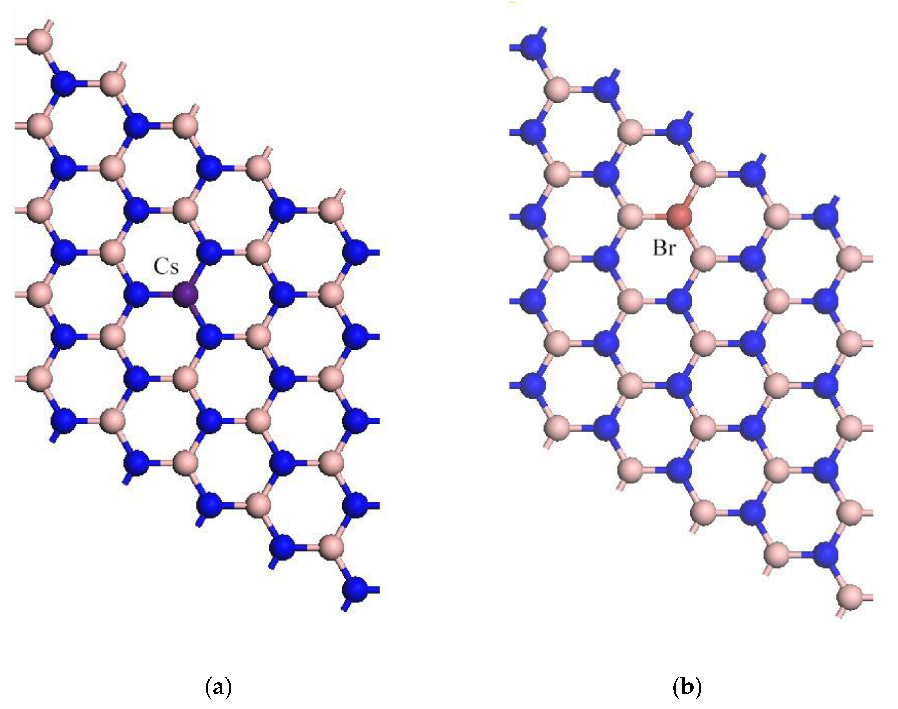
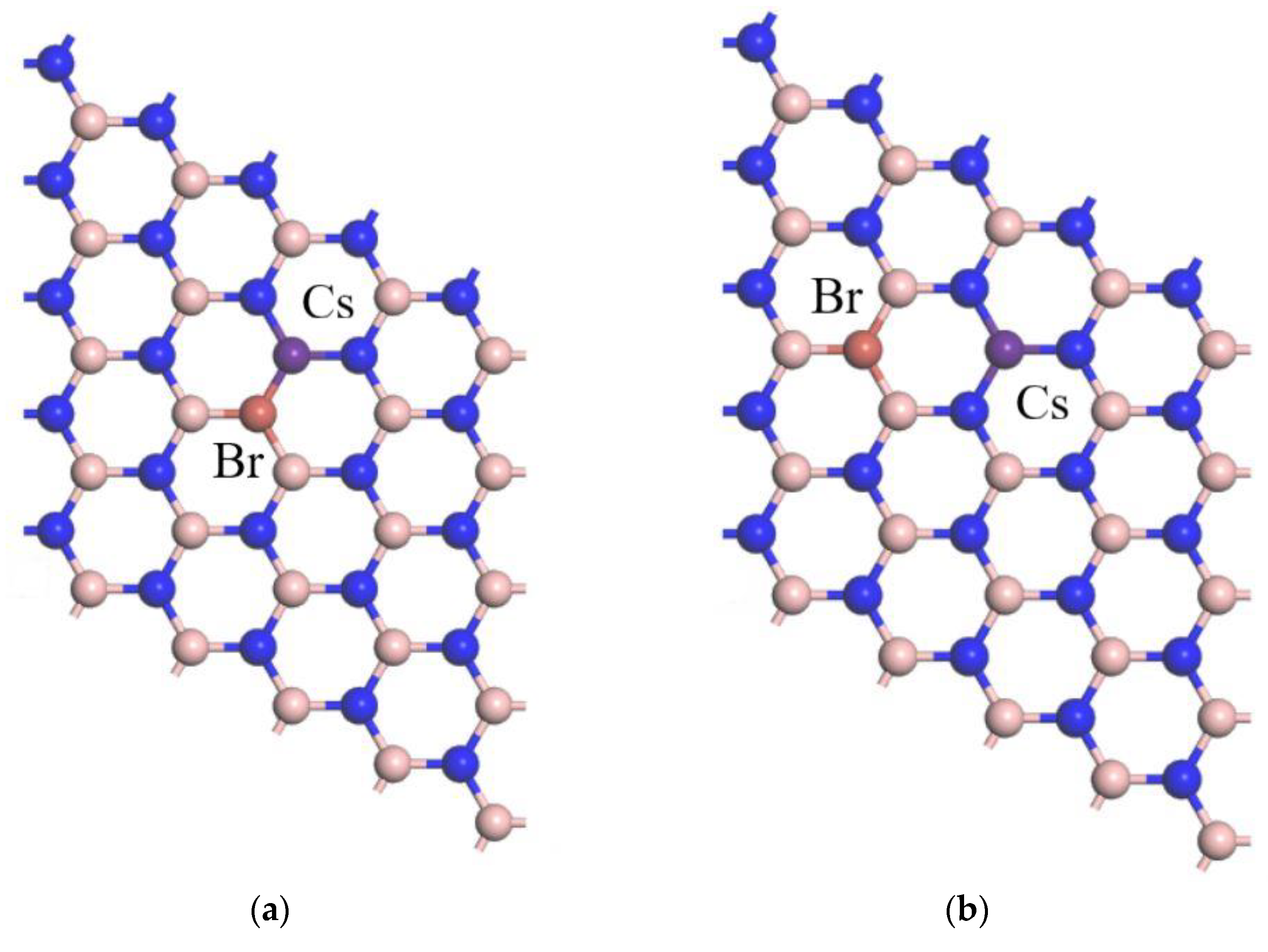
After completing the construction of the primitive cell, a larger scale system needs to be constructed in order to make the calculation results more accurate. In order to balance the computation and accuracy, a 5 × 5 × 1 supercell model is built to describe the boron nitride, which is shown in Figure 1. The doping concentration of both Cs and Br atoms is chosen to be 2%. This is because the established boron nitride supercell is 5 × 5 × 1; with the increasing concentration of doped atoms, the interaction force between the doped atoms will affect the final accuracy and also burden the calculation volume. Figure 2 shows the structure optimization models of Cs-doped, Br-doped, and Cs-Br co-doped h-BN. It is worth noting that different positions of B and N atoms in boron nitride can be doped with different Cs and Br atoms, adjacent and para-positions, due to the special hexagonal structure of BN (Figure 3a,b).
To further verify the stability of the doped h-BN system, the formation energy is an important factor in determining the stability of the system in the total energy of the model system. Thus, the formation energy of each system is calculated using the following equation [44,45,46]:
E f o r m a t i o n = E s y s t e m E b o r o n   n i t r i d e + m μ X n μ d o p a n t
where Esystem is the total energy of h-BN with substitutional doping, E b o r o n   n i t r i d e is the total energy of h-BN, μX is the energy of a single free B/N atom, and μdopant is the energy of a single free dopant atom.
We calculated and obtained the formation energy for the Cs-Br co-doped h-BN model for the ortho-site and para-site at Eortho = 14.519 eV and Epara =10.361 eV. After the analysis and comparison of these models, the co-doped model with Br and Cs para-positions was found to be the most stable.
Table 1 shows the bond lengths for Cs-doped, Br-doped, and Cs-Br co-doped h-BN in a very visual way. In the single-element-doped h-BN model, the bond length of the covalent bond between the Cs atom and the N atom directly connected to it (Cs-N1 and Cs-N2) is 1.64 Å. In addition, the bond length of the covalent bond between the Br atom and the B atom, which directly connects them (B1-Br and B2-Br), is 1.72 Å. More obviously, in Cs-Br co-doped h-BN, the Cs-N bond has a maximum chemical bond length of 1.95 Å. Based on these results, it can be estimated that the molecular structure of Cs-Br co-doped boron nitride was changed compared with that of intrinsic h-BN, and it is rational to believe that its properties have also been changed.

3. Results

3.1. Geometrical Structures

3.1.1. Band Structures and DOS

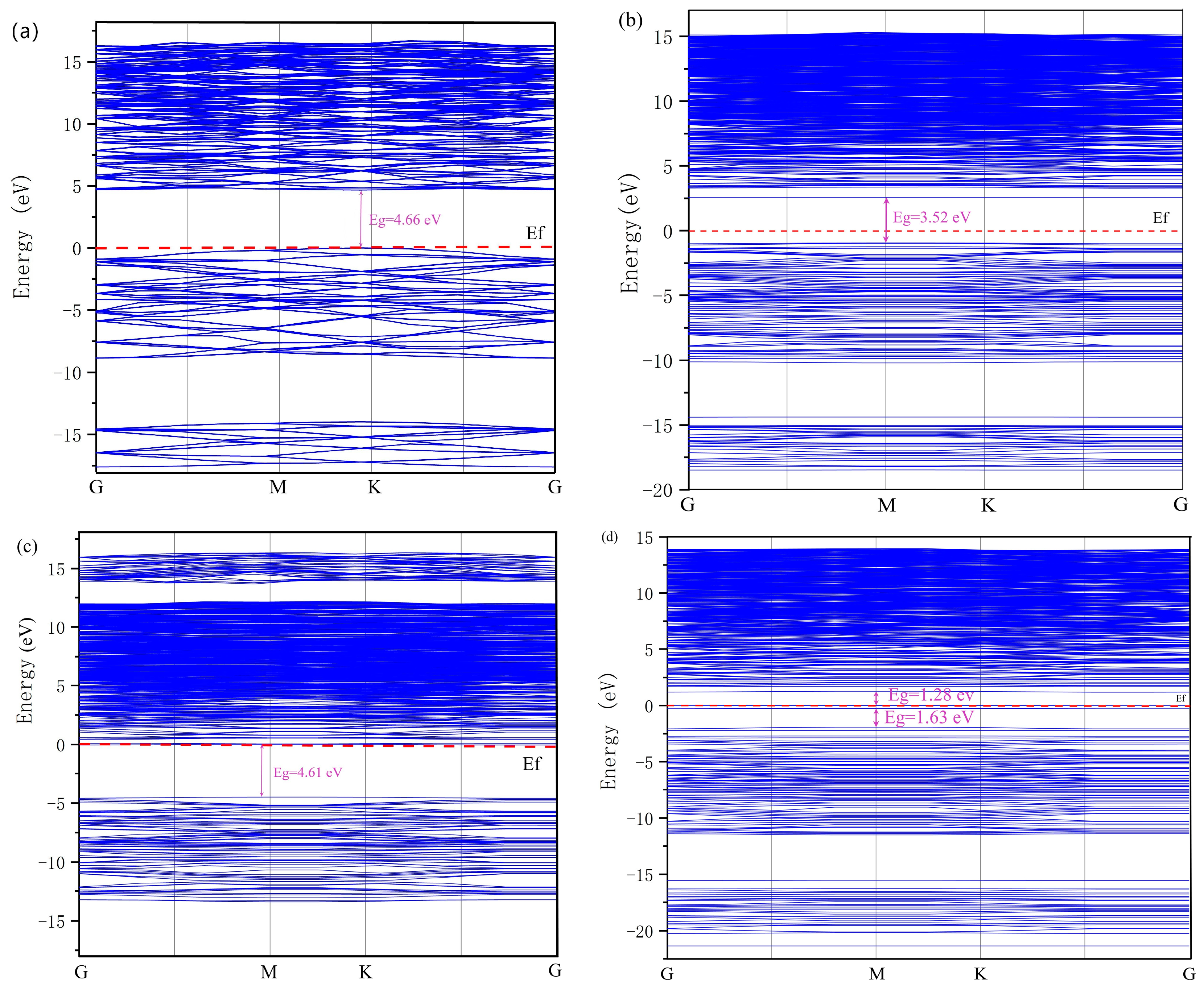
As shown in Figure 4, the band gaps of the intrinsic h-BN and several doped h-BN models are able to be obtained. As shown in Figure 4a, the band gap of the intrinsic h-BN is shown to be 4.66 eV. When the Cs element is used to dope the h-BN, replacing one of the B atoms, the forbidden band width Eg is 3.52 eV. The doping by replacing the B atom flattens the energy fluctuations in the shallow energy level of the valence band of the material, indicating that the effective mass of holes in the material is affected by the doping, and the effective mass of holes in the material is increased by the doping and the localization is enhanced. The Br doping introduces a new impurity energy level in the conduction band, which is closer to the Fermi energy level and therefore the dominant energy level, indicating that the semiconductor material exhibits more pronounced n-type properties. The results of this work are similar to those of Asif’s band structure calculations with Cl-doped boron nitride [33]. The effective mass and localization of carriers do not change obviously after doping. The splitting of some energy levels at the valence band is due to the fact that the Br atom used for doping has more electrons than the original N atom, and according to the bubble incompatibility principle, the orbital energy levels of the electrons are split, leading to the appearance of a new energy band in the conduction band with a final band gap of 4.61 eV.
When Cs-Br is used for doping, it is divided into three main mid-gap states, below and above the Fermi energy level, with respective energy gaps of 1.28, 0.28, and 1.63 eV in the energy range of −1.91 to +1.28 eV. The band gap of h-BN is further contracted to 3.19 eV, introducing two new energy levels above and below the Fermi energy level. Therefore, it can be concluded that the semiconductor properties of doped h-BN are significantly improved, and different doping atoms have different effects on the p/n-type semiconductor properties of h-BN.
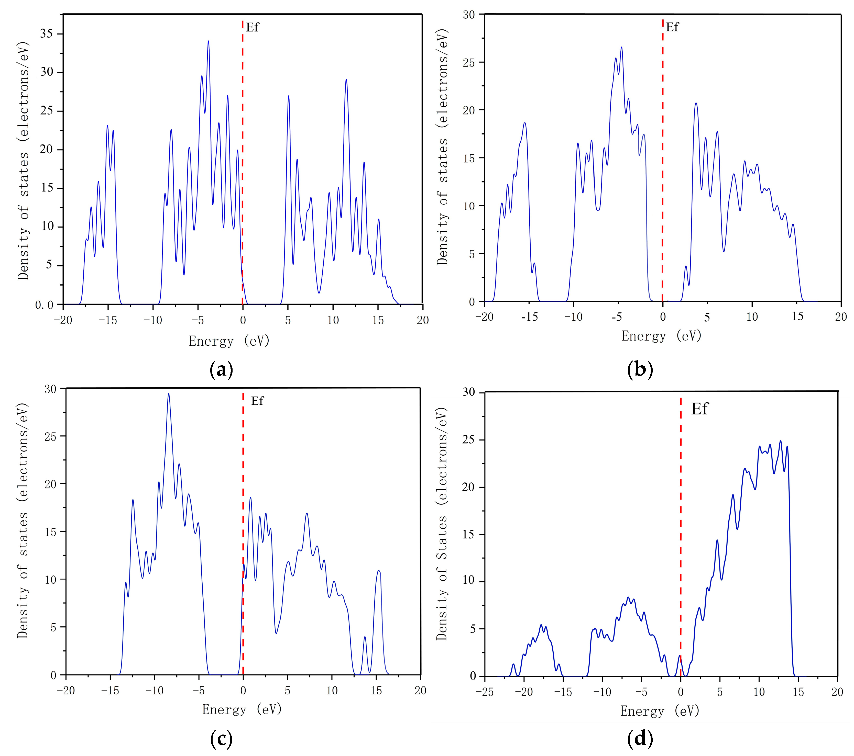
Figure 5b,c, showing the DOS of the boron nitride model with two different doped atoms. Electrons leave the boron atom’s hetero-orbital and are gained by the bromine atom, which gains more electrons in its p-orbital and fewer in its s-orbital in Br-doped h-BN. In contrast, in Cs-doped h-BN, the nitrogen atom captures the electrons, leaving the Cs atom. For Cs-Br co-doped h-BN, a completely different electron gain/loss situation occurs than before (as shown in Figure 5d). When Cs and Br atoms are co-doped with h-BN, the Cs atom loses more electrons than the Cs-doped h-BN, and the Br of the Cs-Br atom co-doped h-BN gains more electrons than the Br-doped h-BN.
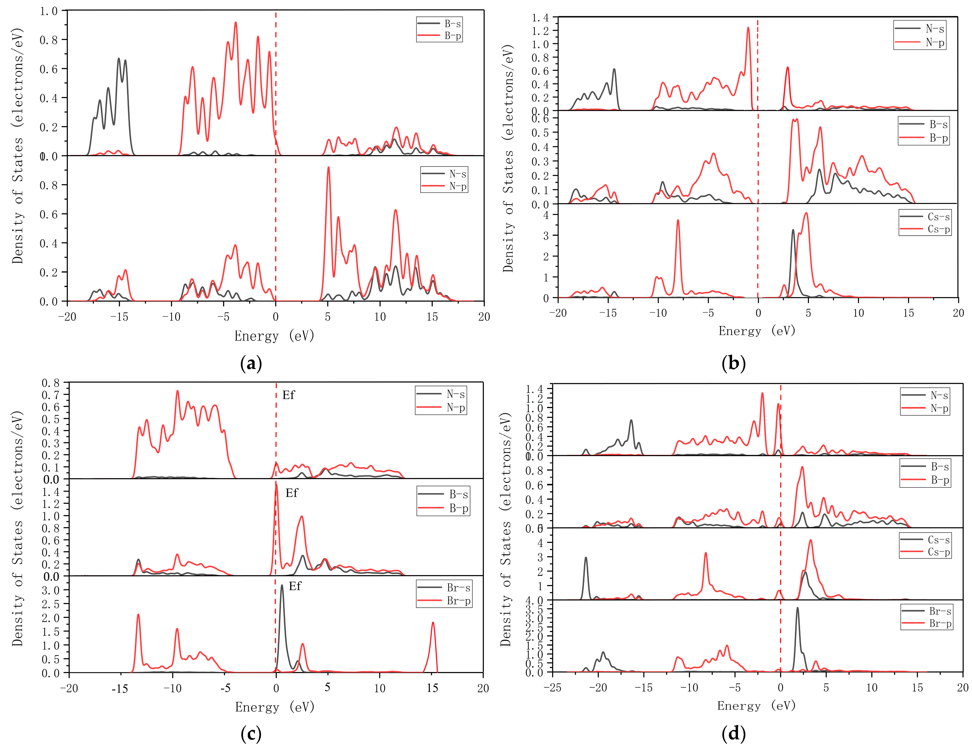
The corresponding partial density of states plots for different cases are given in Figure 6. It can be seen that in the Cs-doped h-BN, the newly introduced impurity states are mainly provided by the 6s orbital of Cs, with a small amount of B 2p and N 2p states, when the conduction band is mainly composed of B 2p, Cs 5p, and Cs 6s. When Br of group VII is used for doping, the overall density of states provided by the B element decreases, and the density of states contributed by Br is mainly located in the deep energy level of the valence band. In this case, the newly introduced impurity states are mainly provided by the 4s orbitals of Br, and the conduction band is mainly composed of B 2p and N 2p, while the p orbitals of Br, B, and N contribute a lot to the valence band. Figure 6(d) shows the density of states of Cs-Br co-doped BN. Cs induces a large charge in the neighboring nitrogen atoms. While B loses most of its valence charge, the empty p orbitals of B combine with the fully occupied and stable p orbitals of Br to form π-bonds, and because of the available lone pairs in the p orbitals of Br, the conduction band minimum in there is a donor state near the Fermi level.
The appearance of an impurity state at the Fermi level is due to overlapping p orbitals of the three atoms (B, N, Cs) involved. However, the appearance of impurity-level states in the conduction band is mainly due to the p orbitals of the B and Cs atoms and the s orbitals of Cs. As the band gap values decrease, the emergence of these impurity states may facilitate electron movement from the valence to the conduction band, tuning the h-BN from insulator to semiconductor.

3.1.2. Electron Density

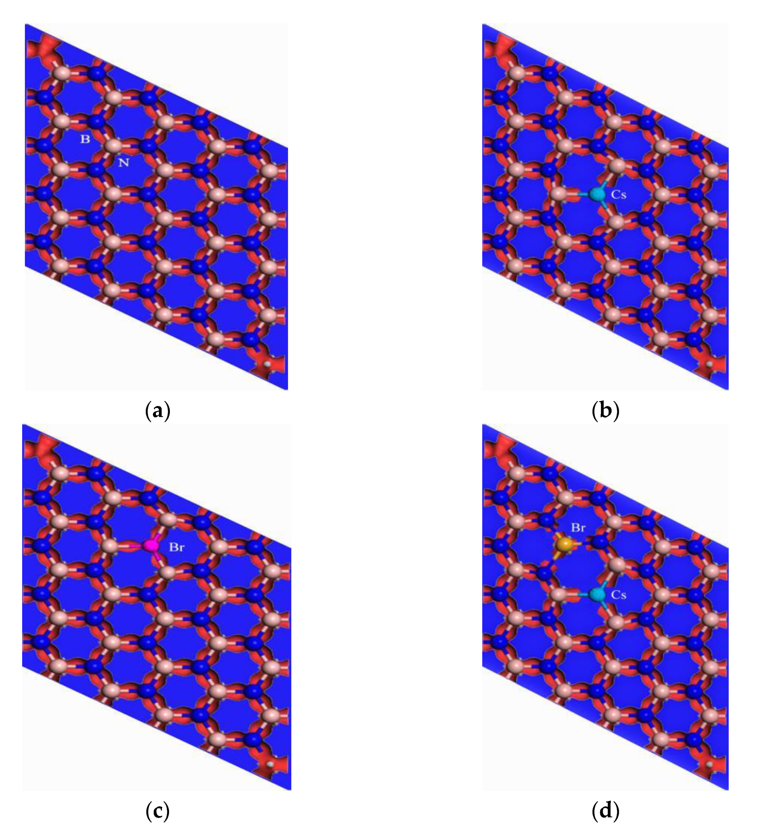
In Figure 7, red represents the richness of the electrons, and blue represents the lack of electrons. The Cs-doped h-BN model has a very good two-dimensional arrangement, with all atoms in the same plane. The electronegativity difference between Cs and N is too large, 3.0 for N and 0.7 for Cs, resulting in a large number of electrons being attracted to N atoms as valence electrons. There are depletion regions with low electron concentrations between the N and Cs atoms, which indicates that the formed Cs-N bond has more ionic bonding factors and is significantly less covalent.
Furthermore, the electronegativity of the Br atom is greater than that of the B atom, but the electron distribution does not favor the Br atom, as shown in Figure 7c. Although for electronegativity, Br atoms are larger than B atoms, replacing N atoms with Br atoms in the already formed equilibrium structure would disrupt the original equilibrium, and the electronegativity of Br atoms is smaller than that of N atoms, while the depletion region of electrons appears between the two adjacent B-Br bonds around Br, indicating that the electrons in the vicinity are strongly bound, which is consistent with the energy band structure showing the electron. This is consistent with the enhanced localization of electrons shown by the energy band structure. Therefore, the strength of the formed B-Br bond is lower and the electron distribution density is smaller than that of the above B-N bond.

3.2. Optical Properties

Complex Dielectric Function

The complex permittivity function is a standard parameter for studying the optical properties of semiconductors; it exhibits a microscopic electronic structure that can be linked to the quantum properties of the material itself for a better analysis of the semiconductor material. It is divided into the real and imaginary parts of the complex dielectric function, and it is described by the following equation:
ε ( ω ) = ε 1 ( ω ) + i ε 2 ( ω )
ε 1 ( ω ) = n 2 k 2
ε 2 ( ω ) = 2 n k
In the above equation, ε 1 ( ω ) is the real part of the complex permittivity function, where n represents the refractive index, ε 2 ( ω ) is its imaginary part, and k is also called the extinction coefficient. According to the Kramer–Kronig relationship, the real part ε 1 ( ω ) represents the phase modulation (dispersion) and the imaginary part ε 2 ( ω ) represents the amplitude modulation (loss/gain).
Since the effect of doping on the boron nitride doping model as a monolayer structure in the z-axis is very small, the doping affects the real part of the complex dielectric function in the y-axis direction only in terms of the magnitude of the peak; when it is 0 eV, the static constant and the position of the two dielectric peaks are the same. The static constant is about 1.44 and the peaks of the two dielectric peaks are around 11 eV and 14.2 eV, respectively. Comparing the results with those of the pure h-BN, it can be found that the substitutional B-doping method reduces the peaks and has a similar effect on the real part of the complex dielectric function to that of the pure h-BN in terms of the peak trend. The similarity is that the peak decreases in all places with respect to the intrinsic h-BN. In addition, the effect of Cs doping on the parameters is mainly in the low energy region of 0–8 eV. Its static dielectric constant increases to 1.86 at 0 eV, followed by a small peak before reaching the first dielectric peak. The difference is that there are no other peaks between 0 eV and the first dielectric peak.
The imaginary part of the complex dielectric function is shown in Figure 8. The non-zero interval of the function values for the pure and doped h-BN, i.e., the range of electron jumps, is essentially the same, with a slight increase in electron jumps in the lower energy region when doped. The number and position of the peaks are the same, but the peaks of the doped h-BN are smaller than those of the pure h-BN. Both peaks of the pure h-BN are not shifted after doping, but the position of the peaks is affected.
In the Cs-doped h-BN, there is a significant electronic transition in the energy span of 1–5 eV, which can be analyzed by combining the energy band structure and PDOS diagram, which is due to the impurity energy level incorporated in the Cs doping, resulting in the electronic transition in the lower energy region. However, the third peak near 15.6 eV is smaller than that of the pure h-BN in the corresponding region.

4. Conclusions

Based on first-principles calculations, the geometrical structures, electronic properties, and optical properties of pure and doped h-BN have been elaborately investigated within the screened Generalized Gradient Approximation functional approximation. After optimization of the doping system, the geometrical structure changes in the mono-layer h-BN are mainly due to the replacement of the original atoms with foreign atoms on the B/N site as impurities. According to our calculations, the wide band gaps decrease with Br, Cs, and Cs-Br doping. The impurities that induce the impurity lines at the Fermi level/energy gap area help to tune the behavior of the system’s wide band gap from that of an insulator to that of a semiconductor. The semiconductor characteristics of doped h-BN are more obvious. Meanwhile, the optical properties of the doped h-BN were also changed. Compared with pure h-BN, the dispersion and extinction coefficients of bromine-doped h-BN transformed to a low energy level state, and the refractive index of light has only one peak with a decreasing trend and little fluctuation; the high-frequency peak becomes wider compared with pure h-BN as well. The optical absorption peaks of Cs-Br-doped h-BN are weaker and more pronounced in low-frequency conditions. In summary, two-dimensional monolayer h-BN can be used in the practical design of optoelectronic devices to select the appropriate doping according to the properties and frequency range of device operation.

Author Contributions

Conceptualization, Z.F.; methodology, H.J.; software, Y.W.; investigation, Y.H.; data curation, Y.F.; writing—original draft preparation, Y.F.; writing—review and editing, W.Z.; supervision, Q.L. All authors have read and agreed to the published version of the manuscript.

Funding

The work is supported by the Project of Innovative and Entrepreneurship Training Program for College Students in Heilongjiang Province (202110214029) and Key Laboratory of Engineering Dielectrics and Its Application (Harbin University of Science and Technology) and the Ministry of Education (Grant No. KFM202006).

Acknowledgments

Y.W. thanks the High Performance Computing Center of Harbin Institute of Technology for calculation resources.

Conflicts of Interest

The authors declare no conflict of interest.

References

  1. Liu, Y.; Cao, Y.; LI, J.; Qiu, Y.; Qin, W.; Wang, Z. 5 kW fiber coupling diode laser for laserprocessing. Opt. Precis. Eng. 2015, 23, 1279–1287. [Google Scholar]
  2. Zhang, J. Design and Analysis of High-Temperature Operating 795 nm VCSELs for 87 Rb Based Chip-Scale Atomic Clock; Ciomp-osa Summer Session: Lasers & Their Applications: Changchun, China, 2011. [Google Scholar]
  3. Xu, H.; Ning, Y.; Zeng, Y.; Zhang, Z.; Qin, L. Design and epitaxial growth of quantum-well for 852 nm laserdiode. Opt. Precis. Eng. 2013, 21, 590–597. [Google Scholar]
  4. Hirayama, H.; Tohro, Y.; Norimichi, N.; Tomoaki, O. 226-273 nm AlGaN deep violet light-emitting diodesfabricated on multilayer AIN buffers on sapphire. Phys. Statussolidi 2008, 5, 2969–2971. [Google Scholar]
  5. Ul Ahmad, A.; Liang, H.; Abbas, Q.; Ali, S.; Iqbal, M.; Farid, A.; Abbas, A.; Farooq, Z. A novel mechano-chemical synthesis route for fluorination of hexagonal boron nitride nanosheets. Ceram Int. 2019, 45, 19173–19181. [Google Scholar] [CrossRef]
  6. Britnell, L.; Ribeiro, R.M.; Eckmann, A.; Jalil, R.; Belle, B.D.; Mishchenko, A.; Kim, Y.J.; Gorbachev, R.V.; Georgiou, T.; Morozov, S.V.; et al. Strong light-matter interactions in heterostructures of atomically thin films. Science 2013, 340, 1311. [Google Scholar] [CrossRef] [Green Version]
  7. Britnell, L.; Gorbachev, R.V.; Jalil, R.; Belle, B.D.; Schedin, F.; Mishchenko, A.; Georgiou, T.; Katsnelson, M.I.; Eaves, L.; Morozov, S.V.; et al. Field-effect tunneling transistor based on vertical graphene heterostructures. Science 2012, 335, 947. [Google Scholar] [CrossRef] [Green Version]
  8. Rodriguez-Vega, E.R.M.; Fischer, J.; Das, S.S. Ground state of graphene heterostructures in the presence of random charged impurities. Phys. Rev. Lett. 2014, 90, 035406. [Google Scholar] [CrossRef] [Green Version]
  9. Govindaraju, N.; Singh, R.N. Chapter 8 Synthesis and Properties of Boron Nitride Nanotubes; EIsevier Inc.: Amsterdam, The Netherlands, 2014; pp. 243–265. [Google Scholar]
  10. Radhakrishnan, S.; Das, D.; Samanta, A.; de Los Reyes, C.A.; Deng, L.; Alemany, L.B.; Weldeghiorghis, T.K.; Khabashesku, V.N.; Kochat, V.; Jin, Z.; et al. Fluorinated h-BN As a magnetic semiconductor. Sci. Adv. 2017, 3, e1700842. [Google Scholar] [CrossRef] [Green Version]
  11. Ismach, A.; Chou, H.; Ferrer, D.A.; Wu, Y.P.; McDonnell, S.; Floresca, H.C.; Covacevich, A.; Pope, C.; Piner, R.; Kim, M.J.; et al. Toward the controlled synthesis ofhexagonal boron nitride films. ACS Nano 2012, 6, 6378–6385. [Google Scholar] [CrossRef]
  12. Van, D.W.; Chris, G.; Catherine, S.; Neugebauer, J. Theory of doping and defects in III-V nitrides. J. Cryst. Growth 1998, 189–190, 505–515. [Google Scholar]
  13. Qurat, A.A.; Akhtar, H.; Hafiz, M.R.; Muhammad, T. Computational study of Be-doped hexagonal boron nitride (h-BN): Structural and Electronic. Comput. Condens. Matter 2020, 23, e00474. [Google Scholar]
  14. Lei, L.; Feng, Y.P.; Shen, Z.X. Structural and electronicproperties of h -BN. Phys. Rev. 2003, 10, 185–192. [Google Scholar]
  15. Tayyab, M.; Hussain, A.; Asif, Q.A.; Adil, W. Band-gap tuning of graphene by Mg doping and adsorption of Br and Be on impurity: A DFT study. Comput. Condens. Matter 2020, 23, e00469. [Google Scholar] [CrossRef]
  16. Hussain, A.; Ullah, S.; Farhan, M.A. Fine tuning the band-gap of graphene by atomic and molecular doping: A density functional theory study. RSC Adv. 2016, 6, 55990–56003. [Google Scholar] [CrossRef]
  17. Lei, W.; Zhang, H.; Wu, Y.; Zhang, B.; Liu, D.; Qin, S.; Liu, Z.; Liu, L.; Ma, Y.; Chen, Y. Oxygen-doped boron nitride nanosheets with excellent performance in hydrogen storage. Nano Energy 2014, 6, 219–224. [Google Scholar] [CrossRef]
  18. Tang, Q.; Zhou, Z.; Chen, Z. Molecular charge transfer: A simple and effective route to engineer the band structures of BN nanosheets and nanoribbons. J. Phys. Chem. C 2011, 115, 18531–18537. [Google Scholar] [CrossRef]
  19. Xu, J.; Wan, Q.; Anpo, M.; Lin, S. Bandgap opening of graphdiyne monolayer via B, N-codoping for photocatalytic overall water splitting: Design strategy from DFT studies. J. Phys. Chem. C 2020, 124, 6624–6633. [Google Scholar] [CrossRef]
  20. Jhi, S.H.; Kwon, Y.K. Hydrogen adsorption on boron nitride nanotubes: A path to room-temperature hydrogen storage. Phys. Rev. B Condens. Matter Mater. Phys. 2004, 69, 1–4. [Google Scholar] [CrossRef] [Green Version]
  21. Liu, Y.J.; Gao, B.; Xu, D.; Wang, H.M.; Zhao, J.X. Theoretical study on Si-doped hexagonal boron nitride (h-BN) sheet: Electronic, magnetic properties, and reactivity. Phys. Lett. Sect. A Gen. At. Solid State Phys. 2014, 378, 2989–2994. [Google Scholar] [CrossRef]
  22. Tang, C.; Bando, Y.; Huang, Y.; Yue, S.; Gu, C.; Xu, F.; Golberg, D. Fluorination and electrical conductivity of BN nanotubes. J. Am. Chem. Soc. 2005, 127, 6552–6553. [Google Scholar] [CrossRef]
  23. Xu, M.; Liang, T.; Shi, M.; Chen, H. Graphene-Like Two-Dimensional Materials. Chem. Rev. 2013, 113, 3766–3798. [Google Scholar] [CrossRef] [PubMed]
  24. Ullah, S.; Hussain, A.; Sato, F. Rectangular and hexagonal doping of graphene with B,N, and O: A DFT study. RSC Adv. 2017, 7, 16064–16068. [Google Scholar] [CrossRef] [Green Version]
  25. Kochaev, A.; Meftakhutdinov, R.; Sibatov, R.; Katin, K.; Maslov, M.; Efimov, V. Enhanced properties of covalently coupled borophene-graphene layers through fluorination and hydrogenation. Appl. Surf. Sci. 2021, 562, 150150. [Google Scholar] [CrossRef]
  26. Kochaev, A.; Katin, K.; Maslov, M.; Singh, S. Covalent and van der Waals interactions in a vertical heterostructure composed of boron and carbon. Phys. Rev. B 2022, 105, 235444. [Google Scholar] [CrossRef]
  27. Kripalani, D.R.; Sun, P.P.; Lin, P.; Xue, M.; Zhou, K. Vacancies and dopants in two-dimensional tin monoxide: An ab initio study. Appl. Surf. Sci. 2020, 538, 147988. [Google Scholar] [CrossRef]
  28. Kadas, K. Ab initio studies of the (111) and (1-1-1-) surfaces of cubic BN: Structure andenergetics. Phys. Rev. B 1998, 58, 15636–15646. [Google Scholar] [CrossRef]
  29. Zhou, Y.G.; Wang, Z.G.; Xiao, H.Y.; Gao, F.; Zu, X.T. Electronic and magnetic properties of metal-doped BN sheet: A first-principles study. Phys. Chem. Chem. Phys. 2010, 12, 7588–7592. [Google Scholar] [CrossRef]
  30. Ambacher, O. Growth and applications of Group III-nitrides. J. Phys. D 1998, 31, 2653–2710. [Google Scholar] [CrossRef]
  31. Beiranvand, R.; Valedbagi, S. Electronic and optical properties of advance semiconductor materials: BN, Al N and Ga N nanosheets from first principles. Opt.—Int. J. Light Electron Opt. 2016, 127, 1553–1560. [Google Scholar] [CrossRef]
  32. Jung, W.G.; Jung, S.H.; Kung, P.; Razeghi, M. Fabrication of Ga N nanotubular material using MOCVD with an aluminium oxide membrane. Nanotechnology 2006, 17, 54–59. [Google Scholar] [CrossRef]
  33. Hussain, A.; Nabi, A.; Tayyab, M.; Rafique, H.M. Computational study of X-doped hexagonal boron nitride (h-BN): Structural and electronic properties (X = P.; S.; O.; F.; Cl). J. Mol. Modeling 2021, 27, 1–15. [Google Scholar]
  34. Yu, C.; Wang, F.; Liu, Y. First principles study of Zn doped cubic BN crystal. Int. Symp. Next Gener. Electron. (ISNE) 2019, 10, 8896476. [Google Scholar]
  35. Said, A.; Debbichi, M.; Said, M. Theoretical study of electronicand optical properties of BN, GaN and BxGaxN in zinc blende and wurtzite structures. Opt.—Int. J. Light Opt. 2016, 127, 9212–9221. [Google Scholar] [CrossRef]
  36. Perdew, J.P.; Burke, K.; Ernzerhof, M. Generalized Gradient Approximation Made Simple. Phys. Rev. Lett. 1996, 77, 3865–3868. [Google Scholar] [CrossRef] [Green Version]
  37. Pease, R.S. An X-ray study of boron nitride. Acta Crystallogr. 1952, 5, 356–361. [Google Scholar] [CrossRef]
  38. Stampfl, C.; Walle, C.G.V.D. Density-functional calculations for III-V nitrides using the local-density approximation and the generalized gradient approximation. Phys. Rev. B Condens. Matter 1999, 59, 5521–5535. [Google Scholar] [CrossRef] [Green Version]
  39. Milman, V.; Winkler, B.; White, J.A.; Pickard, C.J. Electronic structure.;properties.;and phase stability of inorganic crystals: Apseudopotential plane-wave study. Int. J. Quantum Chem. 2000, 77, 895–910. [Google Scholar] [CrossRef]
  40. Lu, Q.; Zhao, Q.; Yang, T.; Zhai, C.; Wang, D.; Zhang, M. Preparation of boron nitride nanoparticles with oxygen doping and a study of their room- temperature ferromagnetism. ACS Appl. Mater. Interfaces 2018, 10, 12947–12953. [Google Scholar] [CrossRef]
  41. Clark, S.J.; Segall, M.D.; Pickard, C.J.; Hasnip, P.J.; Probert, M.I.J.; Refson, K.; Payne, M.C. First principles methods using CASTEP. Z. Krist. 2005, 220, 567–570. [Google Scholar] [CrossRef] [Green Version]
  42. Hamann, D.R.; Schlüter, M.; Chiang, C. Norm-conserving pseudopotentials. Phys. Rev. Lett. 1979, 43, 1494–1497. [Google Scholar]
  43. Chadi, D.J. Special points for Brillouin-zone integrations. Phys. Rev. B 1977, 16, 1746–1747. [Google Scholar] [CrossRef]
  44. Solozhenko, V.L.; Chernyshev, V.V.; Fetisov, G.V.; Rybakov, V.B.; Petrusha, I.A. Structure analysis of the cubic boron nitridecrystals. J. Phys. Chem. Solids 1990, 51, 1011–1012. [Google Scholar] [CrossRef]
  45. Yu, S.S.; Zheng, W.T.; Wen, Q.B.; Jiang, Q. First principle calculations of the electronic properties of nitrogen-doped carbon nanoribbons with zigzag edges. Carbon 2008, 46, 537–543. [Google Scholar] [CrossRef]
  46. Chen, H.X.; OuYang, F.P.; Ma, S.S.; Wu, X.Z.; Xiao, J. First-principles investigation on B/N codoping of metallic carbon nano-tubes. Phys. Lett. A 2010, 374, 4343–4348. [Google Scholar] [CrossRef]
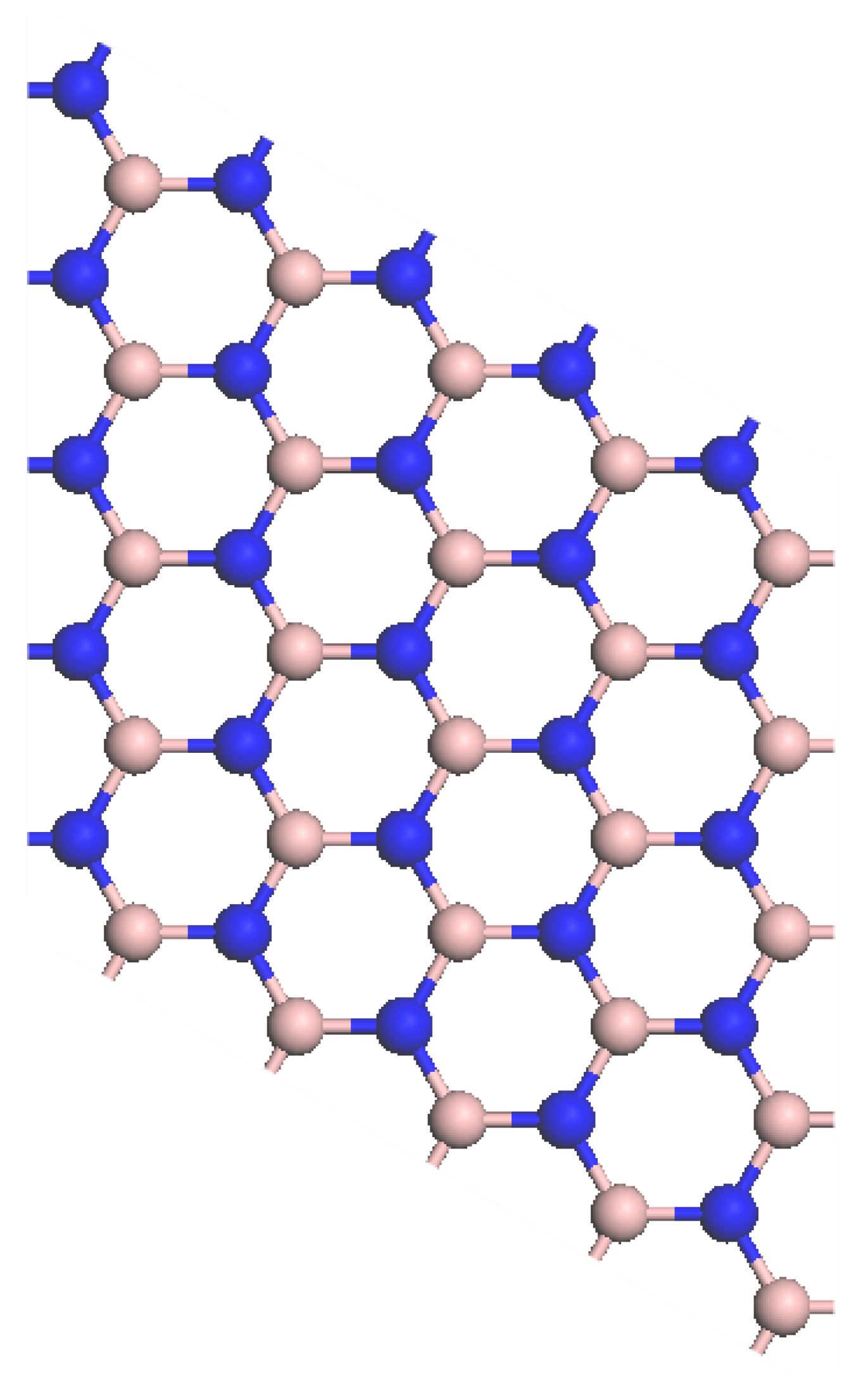
Figure 1. Intrinsic h-BN model.
Crystals 12 01406 g001
Figure 2. Model of Cs-doped (a) and Br-doped (b) h-BN.
Crystals 12 01406 g002
Figure 3. Model of Cs-Br (a,b) co-doped h-BN.
Crystals 12 01406 g003
Figure 4. Band structures of (a) intrinsic, (b) Cs−doped, (c) Br−doped, and (d) Cs−Br co−doped h-BN.
Crystals 12 01406 g004
Figure 5. Total density of states for (a) intrinsic, (b) Cs−doped, (c) Br−doped, and (d) Cs−Br co−doped h−BN.
Crystals 12 01406 g005
Figure 6. PDOS for intrinsic and doped boron nitride: (a) intrinsic, (b) Cs−doped, (c) Br−doped and (d) Cs−Br co−doped h-BN.
Crystals 12 01406 g006
Figure 7. Electron density of intrinsic and doped h-BN charges. (a) intrinsic, (b) Cs-doped, (c) Br-doped and (d) Cs-Br co-doped h-BN.
Crystals 12 01406 g007
Figure 8. Complex dielectric function of (a) intrinsic, (b) Cs-doped, (c) Br-doped, and (d) Cs-Br co-doped boron nitride.
Crystals 12 01406 g008aCrystals 12 01406 g008b
Table 1. Bond lengths of Cs-N, B-Br, and B-N in different models.
ModelsBond TypeBond Length (Å)
Intrinsic boron nitrideB-N1.42
Cs-dopedCs-N11.64
Cs-dopedCs-N21.64
Br-dopedB1-Br1.72
Br-dopedB2-Br1.72
Cs-Br co-dopedB-Br1.93
Cs-Br co-dopedCs-N1.95
Publisher’s Note: MDPI stays neutral with regard to jurisdictional claims in published maps and institutional affiliations.