1. Introduction
At the present time there is a need for inexpensive but highly effective technologies for surface modification and deposition of protective coatings, allowing increases in the operational characteristics of steel products. Knowledge of the laws of diffusion processes and the study of the kinetics of transformations occurring during coating deposition will significantly increase the efficiency of the search for optimal methods of their treatment. Currently, the most effective is considered the use of high-speed coating spraying technologies, which are characterized by high productivity, universality and ease of control of technological parameters. Further, methods of product surface treatment using combined technologies, which stimulate the process of changing the structural-phase state of the material, thereby obtaining a modified surface layer or coating with the desired properties, are intensively developing.
Obtaining multifunctional composite coatings based on MAX-phase (ternary carbides M
n+1AC
n and nitrides M
n+1AN
n, M—transition metal, A—element of IIIA or IVA subgroup) presents particular interest [
1,
2,
3]. Interest in MAX-phases (e.g., titanium carbosilicide, Ti
3SiC
2) is explained by its unique combination of the properties of metal and ceramics: as a ceramic, it is hard, light, high-strength and wear-resistant, and it has a high melting point and can be easily processed like metals. Among the newest composite materials includes the family of so-called MAX compounds, which represent carbides and silicides corresponding to the formula Ti
3SiC
2. Due to the features of the crystal lattice structure, Ti
3SiC
2 is characterized by a unique combination of physical, chemical and mechanical properties. Further, Ti-Si-C systems have good performance in abrasive wear, corrosion, as well as being relatively low cost [
4,
5,
6]. The combination of high wear resistance and corrosion resistance allows the use of this material as wear-resistant coatings. However, despite the uniqueness of the useful properties in practical terms, both solid materials and coatings made of Ti
3SiC
2 have not found wide applications in production so far. One of the limiting factors for the widespread use of Ti
3SiC
2 coatings is the difficulty in obtaining it as a single-phase product due to the decomposition of the MAX phases at high coating temperatures. Obtaining coatings with relatively high Ti
3SiC
2 content is possible in some methods of gas-thermal spraying, in particular, in detonation spraying, which is carried out by using a gas explosion to accelerate and heat up the particles of the sprayed powder material [
7,
8,
9,
10].
Our previous papers [
11,
12,
13] present the results of studies of the structural-phase composition and mechanical-tribological properties of Ti
3SiC
2-based coatings depending on the detonation of spraying modes. The analysis of the experimental results shows the dependence of the structural-phase state and properties of the coatings on the technological parameters of detonation spraying. Based on the results of X-ray phase analysis and SEM, it can be stated that increasing the detonation barrel filling volume with explosive gas mixture up to 70% due to high-temperature shock wave causes decomposition of titanium carbosilicide (Ti
3SiC
2) powder and a decrease in its volume fraction in the composition of the coatings. Consequently, additional research and development of new methods of coatings processing are required to entrain the volume fraction of the MAX phase. We found that increasing the volume fraction of Ti
3SiC
2 provides high mechanical and tribological properties to the coatings.
The structure and properties of detonation coatings based on Ti-Si-C can be controlled with subsequent heat treatment. The results given in [
11,
13,
14,
15,
16,
17,
18] confirm that increasing the volume fraction of Ti
3SiC
2 provides high mechanical and tribological properties to the coatings. Thermal stabilization helps to minimize the residual strain and residual stress but has some disadvantages. For example, heat treatment has a significant time duration and high energy consumption. In addition, there is a need for the design and manufacture of associated tooling, as well as high capital costs for the purchase and installation of large-sized furnaces. It also has disadvantages associated with the weakening of the substrate material. The disadvantages of traditional heat treatment methods can be overcome by thermal activation of the surface by pulse-plasma flows [
19]. The advantages of pulse-plasma technology are high rates of heating and cooling of the material’s surface (10
4–10
8 Ks
−1), the possibility of creating layered structures with different phase compositions and, accordingly, different physico-chemical characteristics [
20]. Further, an advantage is the possibility of the local impact on the product by pulsed plasma.
In the literature, there is no data on the effect of pulse-plasma treatment on the structural and phase transformations in the detonation coatings based on Ti-Si-C. Therefore, the study of the structure and phase composition of detonation coatings based on MAX phases (Ti3SiC2) after pulse-plasma treatment seems relevant.
3. Results and Discussion
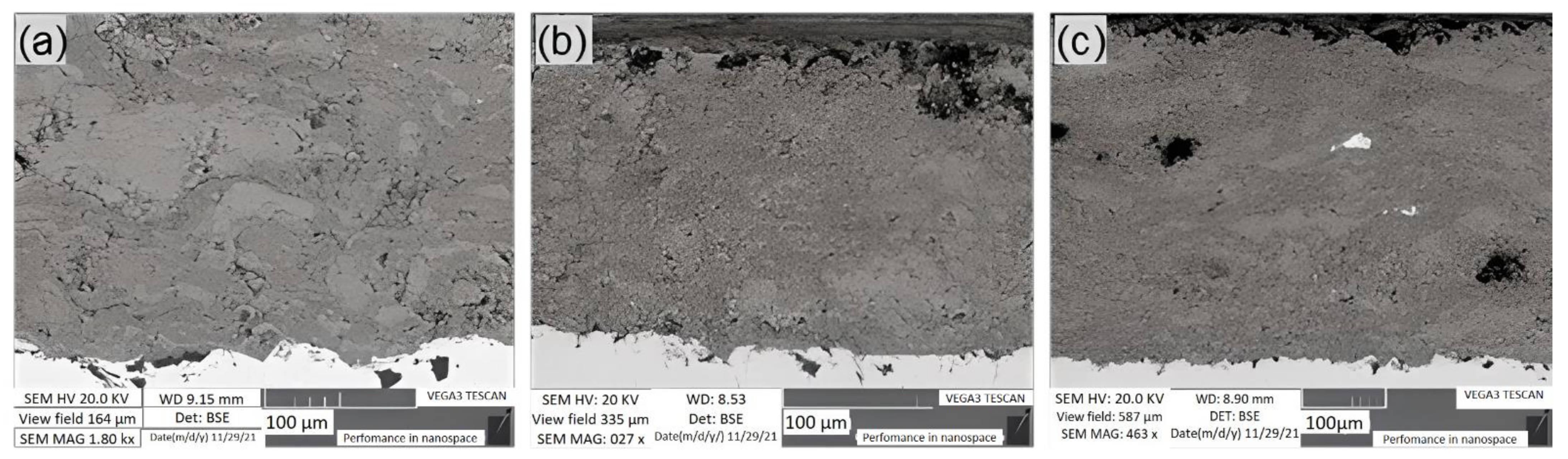
The cross-sectional microstructure of the coatings after pulse-plasma treatment obtained at different distances between the treated surface and the plasmatron is shown in
Figure 1. After pulse-plasma treatment, no peeling of the coatings from the substrate (U9 steel) was observed. At a distance of 30 mm, due to the high energy density, the surface of the sample was melted and vaporized. The generalized index of porosity and the particles that had been cut out during the preparation of the specimens decreased after the treatment at a distance of 40 mm (
Figure 1b). The structure of the coatings aligned after pulse-plasma treatment (
Figure 1b). The coating treated at a distance of 50 mm is characterized by an average lamella content, an average degree of dissociation of silicon and minimal porosity compared to the other modes (
Figure 1c). Based on the obtained data, pulse-plasma treatment at a distance of 50 mm is the most optimal.
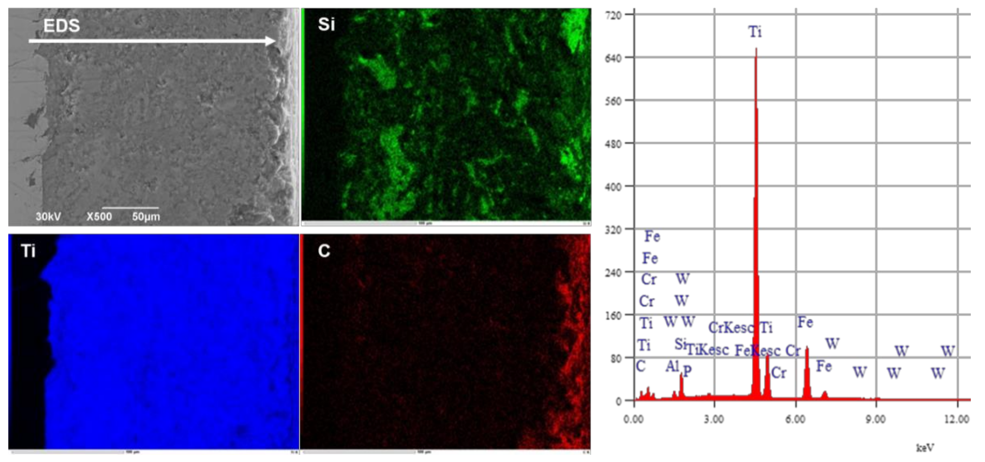
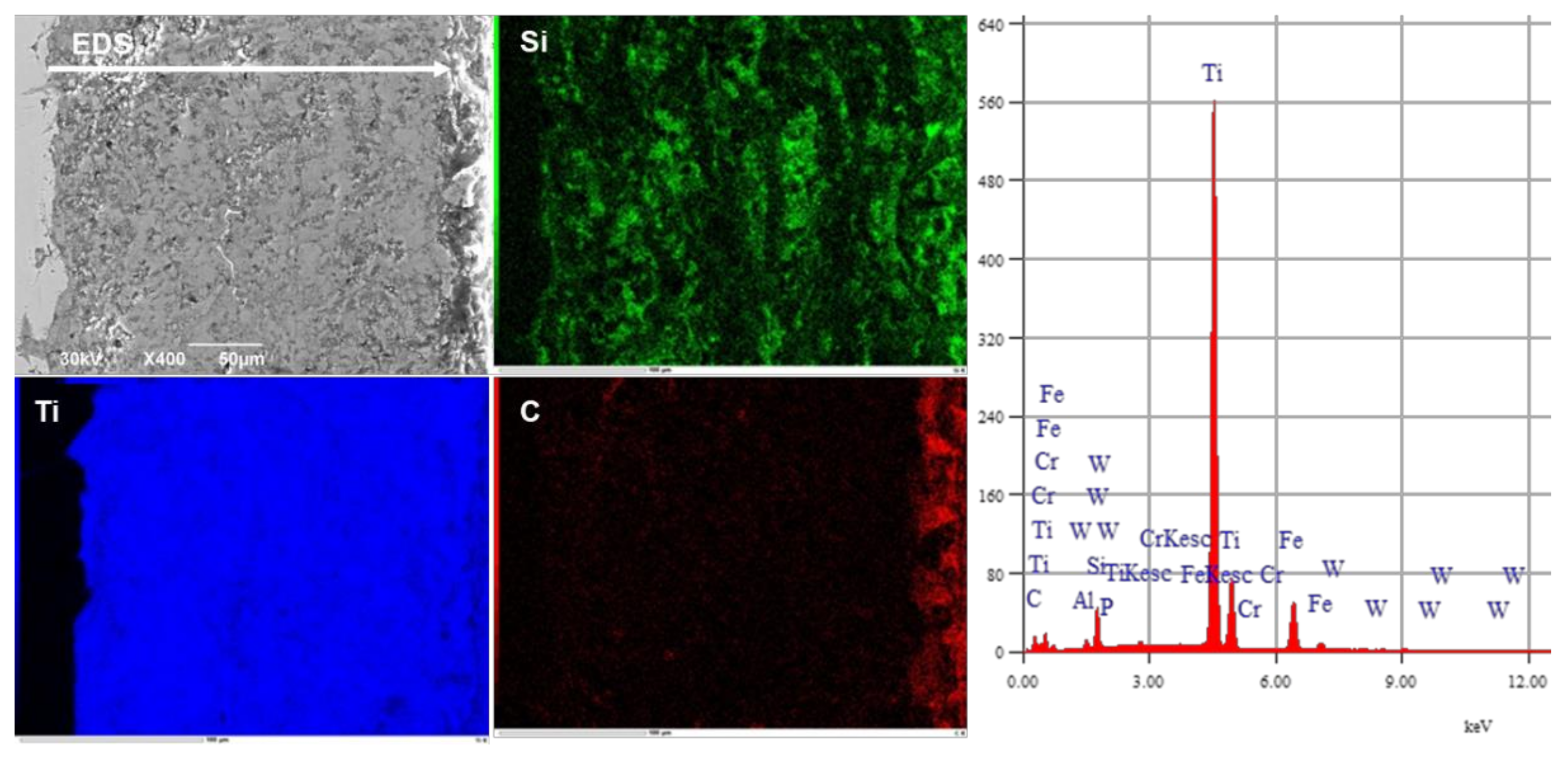
The distribution of structural elements can be estimated on the basis of the results of EDS analysis (element mapping on the cross-section of the coatings). The chemical composition of the coatings after the pulse-plasma treatment consists of the elements Ti, Si and C (
Figure 2,
Figure 3 and
Figure 4). Further, the presence of tungsten W was recorded in the coatings. Taking into account that tungsten was used as an eroding electrode and during the treatment, the electrode was vaporized, and tungsten particles were present in the plasma jet, its presence on the coating surface is logical. For example, in work [
25], when using an expendable electrode made of titanium, it was found in the hardened layer at a depth of up to 20 μm. A fairly uniform distribution of structural elements is observed after the PPT at a distance of 50 mm.
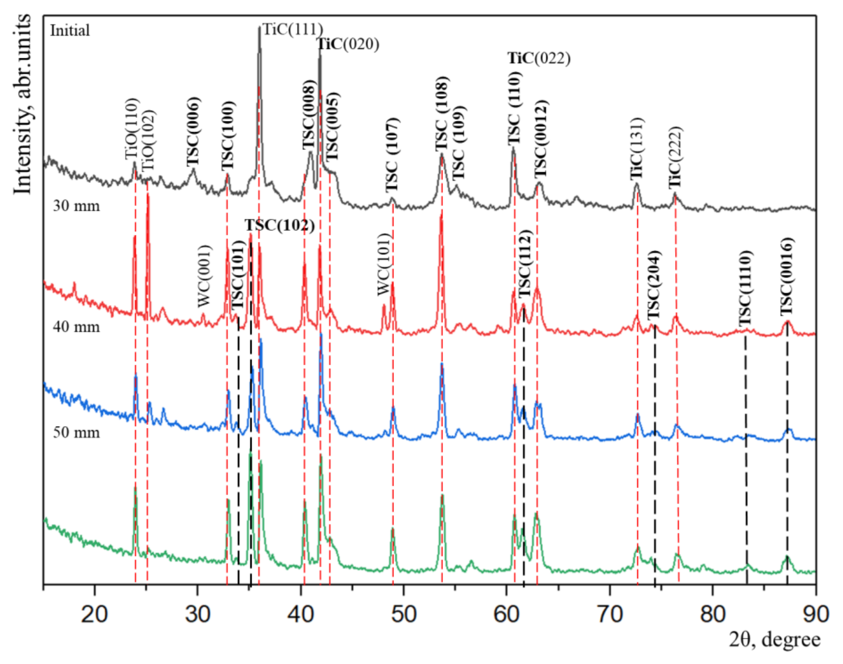
Figure 5 shows the diffractograms of the detonation coatings of the Ti-Si-C system before and after the pulse-plasma treatment. The results of the X-ray phase analysis of the coatings showed that the main phase after the detonation spraying is titanium carbide (TiC, phase content, 61 wt.%) with a cubic lattice (a = 4.3233 Å) and a relatively small fraction of titanium carbosilicide phase (Ti
3SiC
2, phase content, 39 wt.%) with a hexagonal lattice (a = 3.0718 Å, c = 17.6894 Å). The interplanar distances calculated from the reflections after the pulse-plasma treatment allow us to speak about the presence of the following phases in the coating: TiC with a cubic lattice (a = 4.3089 Å), Ti
3SiC
2 with a hexagonal lattice (a = 3.1402 Å, c = 17.7388 Å), WC with a hexagonal lattice (a = 5.0874 Å, c = 13.7310 Å) and TiO
2 with a tetragonal lattice (a = 4.6223 Å, c = 2.9468 Å). After the pulsed plasma treatment, an increase in the intensity of the titanium carbosilicide (Ti
3SiC
2) peaks was observed; moreover, numerous new reflections related to this phase (101, 102, 112, 204, 1110, 0016) were identified in the diffractogram, which indicates an increase in the titanium carbosilicide (Ti
3SiC
2, phase content, 62 weight%) phase. The change in the phase fraction indicates a solid-phase transformation during pulse-plasma activation associated with heating above the melting point and cooling of the samples during processing. The rate of sample cooling and crystallization of the melt (treated layer) depends on the heat capacity of the base metal (substrate). Further, in the diffractograms, the coatings are present in insignificant amounts of carbide and oxide phases: WC and TiO
2. The samples were treated in an air environment, which caused the formation of oxide phases. Tungsten carbide is formed due to the consumption of the tungsten electrode [
18].
Images of the thin structure of the coatings obtained by viewing in an electron microscope were used to classify the morphological features of the structure. The phases were identified by images confirmed by microdiffraction patterns and dark-field images obtained in the reflexes of the corresponding phases. In order to identify the crystal bonds between Ti3SiC2 and TiC, the Ti3SiC2/TiC interfaces were studied by transmission electron microscopy. The crystallographic structure and bonding between the Ti3SiC2 and TiC phases were determined by diffraction methods on a selected area and by microdiffraction.
Before describing the interphase structure and crystallographic relationships, it is important to understand the crystal structure of the phase components of Ti
3SiC
2-based coatings called MAX phases. The main phase component of Ti
3SiC
2-based detonation coatings is Ti
3SiC
2 and TiC.
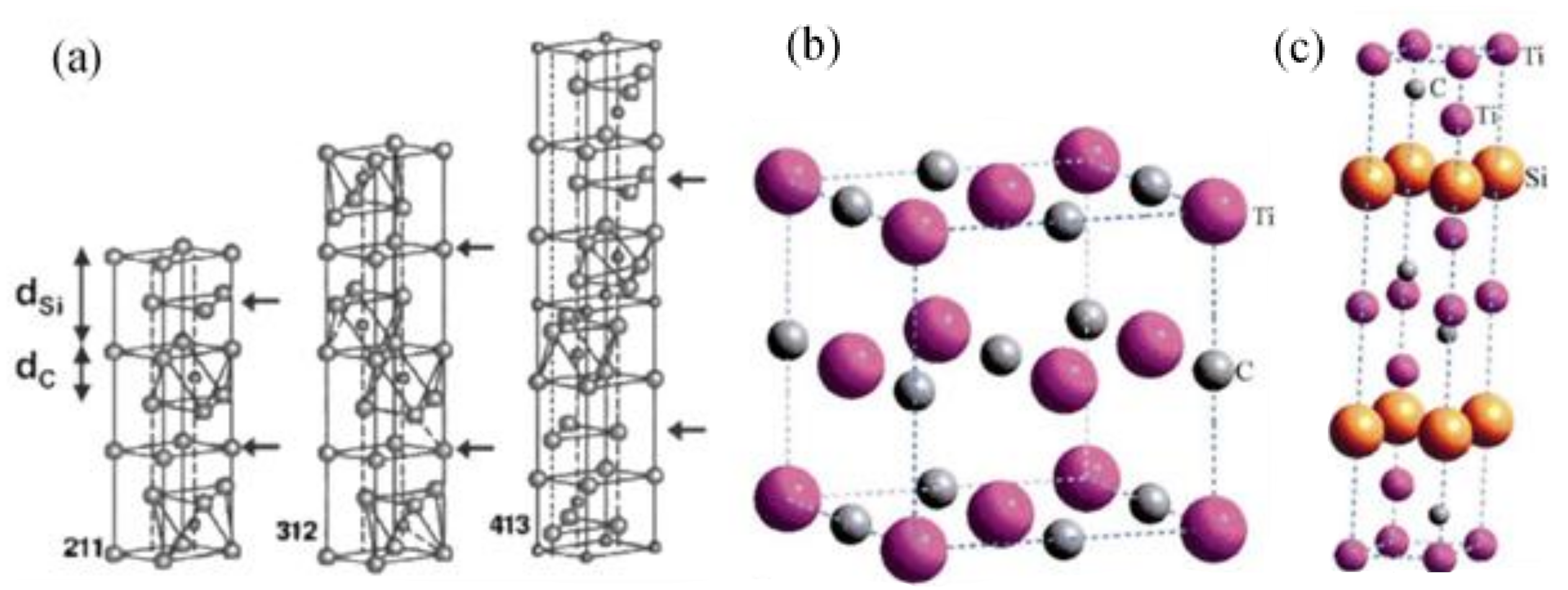
Figure 6 represents the crystal structures from the literature sources [
3,
4,
26]. The hexagonal unit cell of MAX phases presented in
Figure 6c refers to P63/mmc space group and has two formula units in structure: M-X and A. The unit cell of Ti
3SiC
2 consists of a Ti
3C
2 carbide layer (M-X) and is separated by atomic layers of silicon (A—element of IVA subgroup). According to the literature, scientists Barsoum Michel W. and his co-authors, as well as another group of researchers, Zhang H.Z. and Wang S.Q. [
12], found that the bond Ti-Si is weaker than the bond Ti-C in the structure of Ti
3SiC
2. This is indirectly confirmed by the fact that the amplitude of the vibrational atom Si is larger than that of Ti, which also indicates that the connection of M-X is stronger than the M-A connection in most MAX phases [
27].
The Ti-C bonds are mostly metallic, with covalent and ionic components and have exceptional strength, while the Ti-Si bonds are relatively weak (especially in shear). Ti
3SiC
2 has a close crystallographic relationship with its binary titanium carbide TiC (
Figure 1b).
Figure 6a shows three different crystal structures of M
2AX, M
3AX
2 and M
4AX
3 compounds labeled 211, 312 and 413, respectively. According to source [
28], the mentioned structures could be described as nanolaminate with layers of binary MX carbide or nitride interspersed with one layer of A atoms, where the insertion of A layers means that MA bonds replace MX bonds. It is also noted that the difference between, for example, Ti
3SiC
2 and pure TiC is the presence of single trailing interstitial C atoms replaced by Si layers. In addition, the TiC nanolaminate layers on each side of the inserted Si layers are twinned with the Si layer as the mirror planes 1, 3, 4.
Thus, it was found that the phase structures M
n + 1AX
n for n = 1, 2 and 3, give three known subgroups, which are designated as 211, 312 and 413. It has also been known from the literature that each structure shows one-unit cell, and the arrows in
Figure 6a show Si layers. The
c-axis can be predicted in any given MAX structure by adding the correct number of Ti-Si-Ti and Ti-C-Ti distances marked in
Figure 6a as dSi and dC [
29].
When reviewing the published works of other researchers [
30] on the synthesis of titanium carbosilicide, it was found that no matter what technology was used, the main morphological components of carbosilicide coatings are the phases of carbosilicide (Ti
3SiC
2) and titanium carbide TiC. It also became obvious that, on the one hand, TiC phases are always present as the main phase, and, on the other hand, titanium carbide phases are used as one of the starting materials for the synthesis of Ti
3SiC
2 carbosilicide. This possibly means that TiC phases can transform into Ti
3SiC
2 in the presence of silicon, Si.
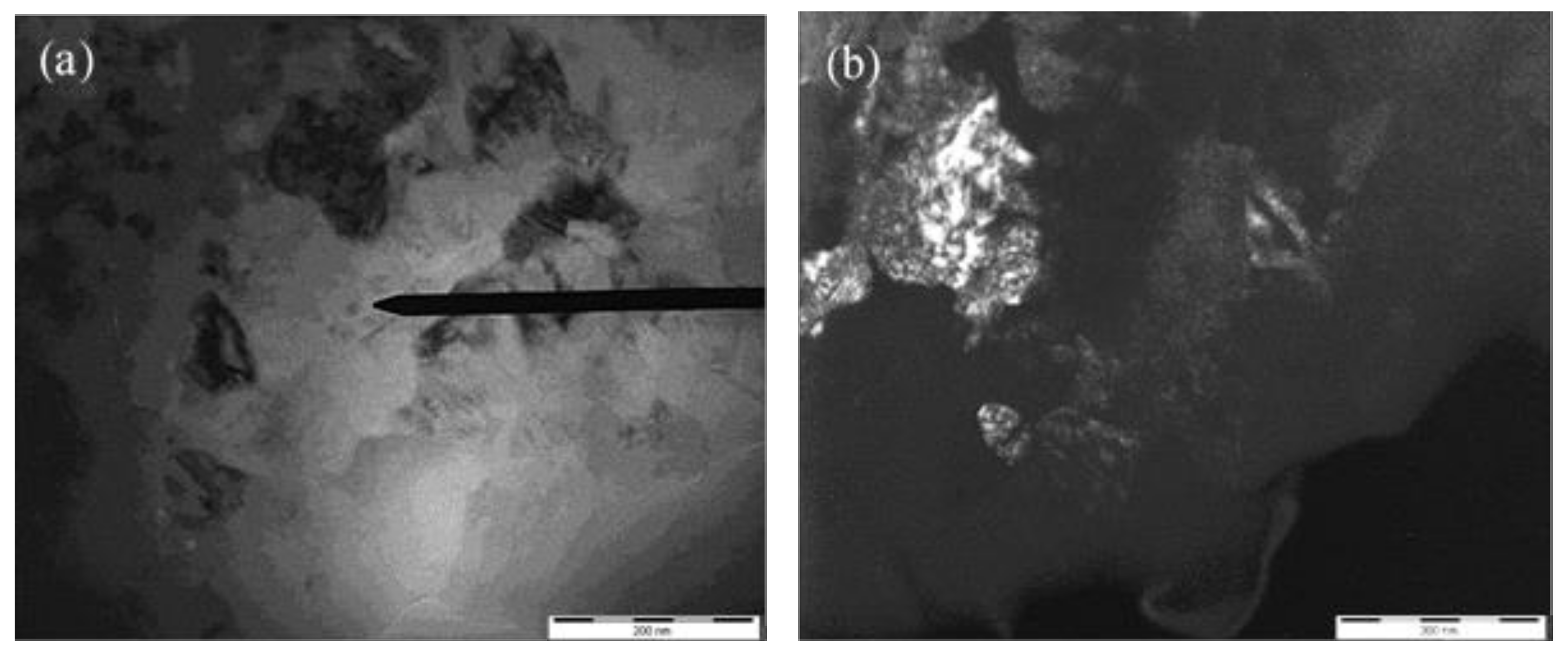
Brightfield and darkfield transmission electron microscopic images of the thin structure of the Ti
3SiC
2-based detonation coating before and after pulse-plasma treatment are shown in
Figure 7. The TEM image in
Figure 7a shows that the TiC and Ti
3SiC
2 grains still retain their original rounded shape and curved rod shape after pulse-plasma treatment, respectively (
Figure 7b). No significant grain growth was observed in the pulse-plasma treatment, and the grain size remained below the average allowable size.
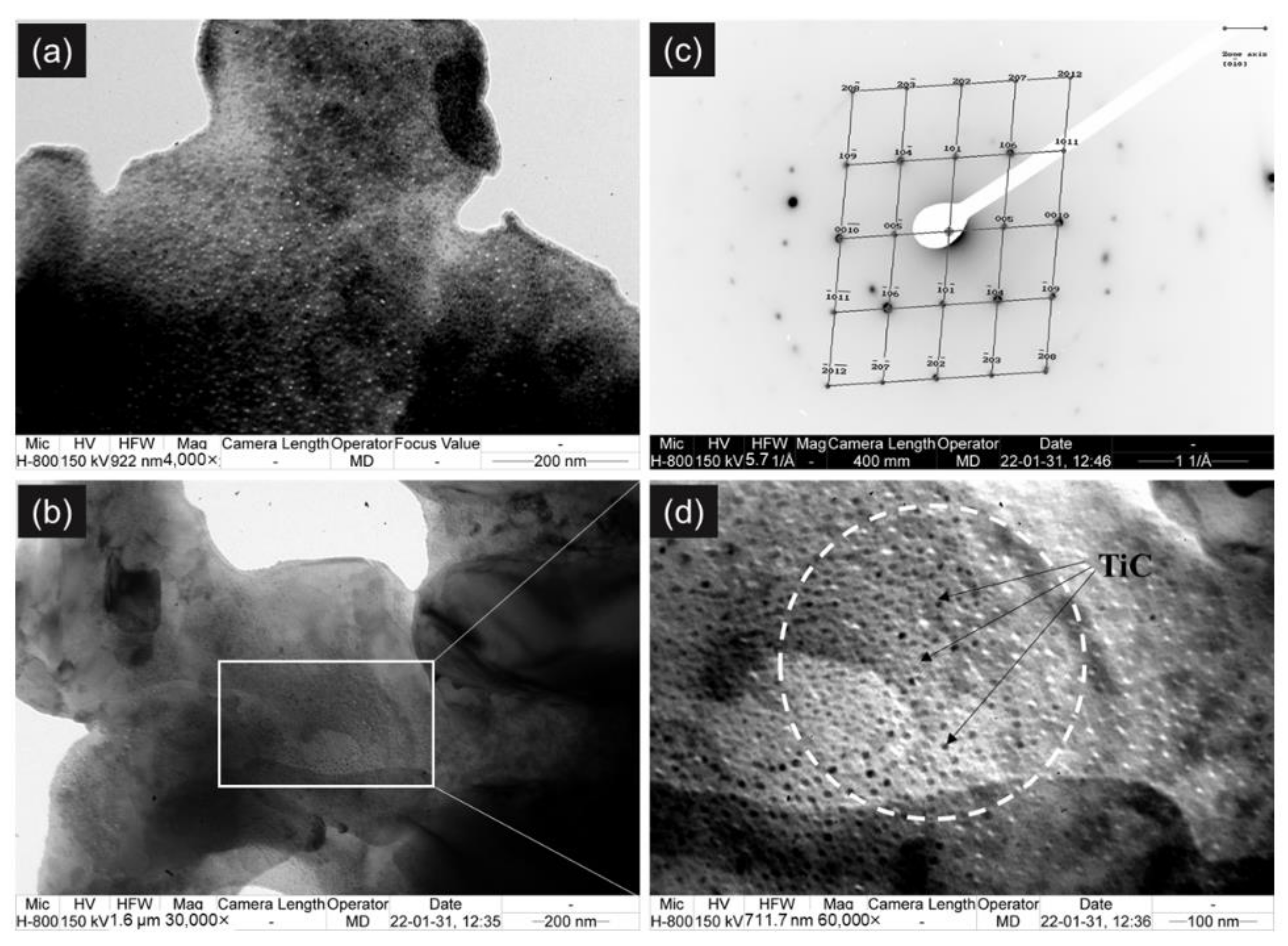
As shown in
Figure 8a, after pulse-plasma treatment (annealing), the void fraction (pores) and particle area decreased, and the microstructure became more homogeneous, which resulted in the densification of the Ti
3SiC
2-based detonation coating. The TEM images in
Figure 8b,d show the interface between the main phases of Ti
5Si
3 and TiC. According to the microdiffraction pattern obtained from the rectangular section in
Figure 8c and its individuated pattern, which shows reflexes of the [0
0] Ti
3SiC
2 carbosilicide plane, the ternary Ti
3SiC
2 phase is observed in the nanoscale composite matrix. As found in
Figure 8d, the Ti
3SiC
2 phase has a lamellar layered substructure, which, according to literature sources, positively affects the strength and impact toughness of coatings [
31,
32,
33].
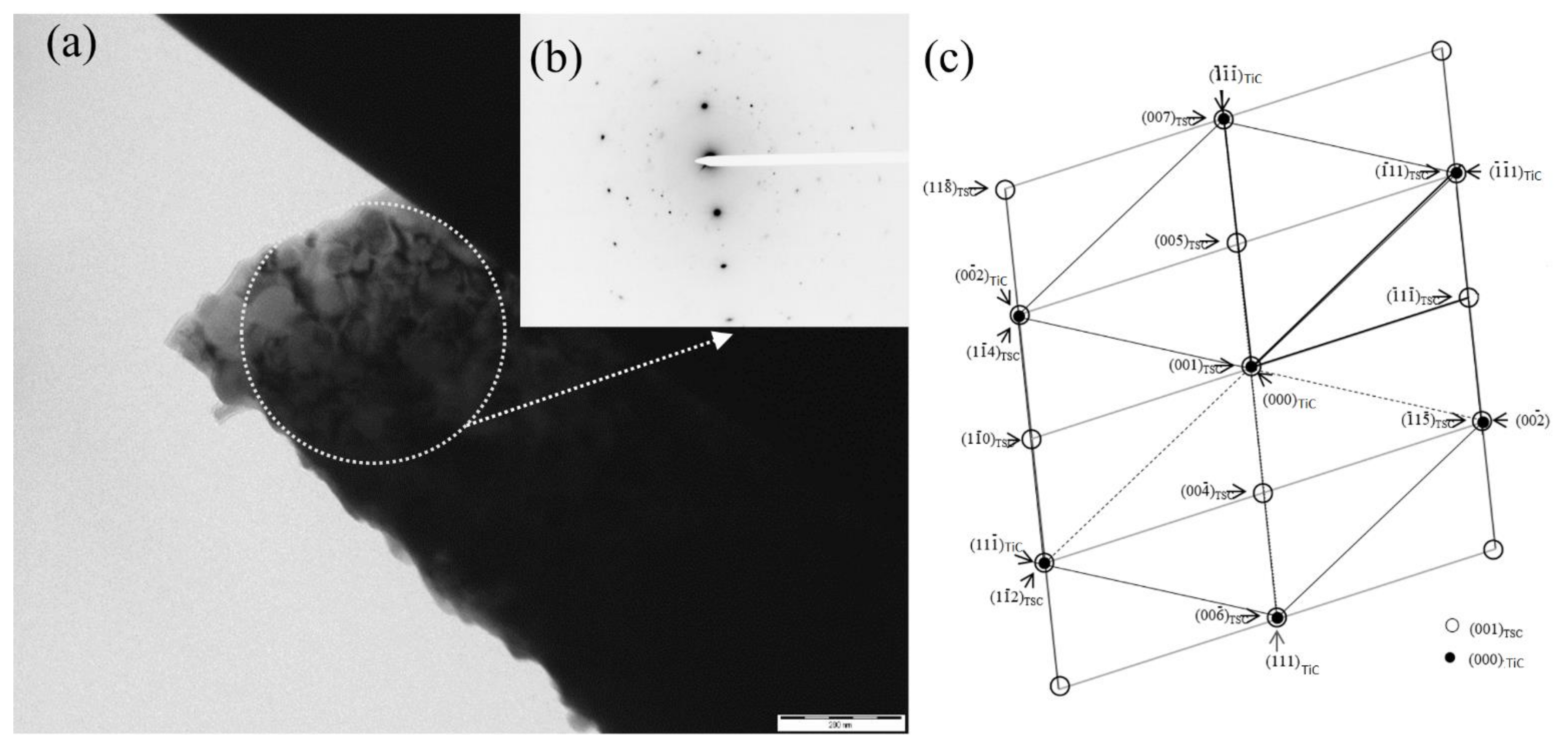
Another confirmation of the formation of MAX phases is the TEM image and the microdiffraction pattern with an indexed scheme of the substructure of the detonation coating based on Ti
3SiC
2 after pulse-plasma treatment, as shown in
Figure 9: where a—brightfield image of the thin structure of Ti
3SiC
2 coating with highlighting of a circular area for microdiffraction, b—microdiffraction pattern obtained from the highlighted area in (a); c—the indexed diagram, in which there are plane (001) Ti
3SiC
2 reflections of carbosilicide marked with “○” and titanium carbide (000) TiC marked with “●” symbol, whose directions are shown by arrows.
Thus, the detonation spraying process followed by pulse-plasma treatment resulted in a Ti3SiC2-based coating, with [00] carbosilicide plane reflections, a lamellar layered structure, and reduced porosity.
In a further study of the properties of the coatings obtained at different PPT distances, along with electron microscopy and X-ray diffraction analysis of the sample structure, we measured their mechanical and tribological properties as important indicators of the formation of high-strength phases. The Vickers hardness of Ti-Si-C detonation coatings before and after pulse-plasma treatment is presented in
Table 1. The microhardness of the coatings after pulse plasma treatment has a high value compared to the original coating. The microhardness value depends on the treatment distance. High hardness is observed after pulse-plasma treatment at a distance of 50 mm (~1785 HV), and hardness decreases as the plasma torch gets closer to the treated surface. This may be due to the degree of localized melting of the material, which depends on the distance of exposure to pulsed plasma.
To assess the resistance of Ti-Si-C coatings to abrasion and erosion wear, tests were carried out on special stands. Comparative studies of wear resistance of coatings under friction in an abrasive environment showed that the coatings after plasma treatment modification provide the highest wear resistance.
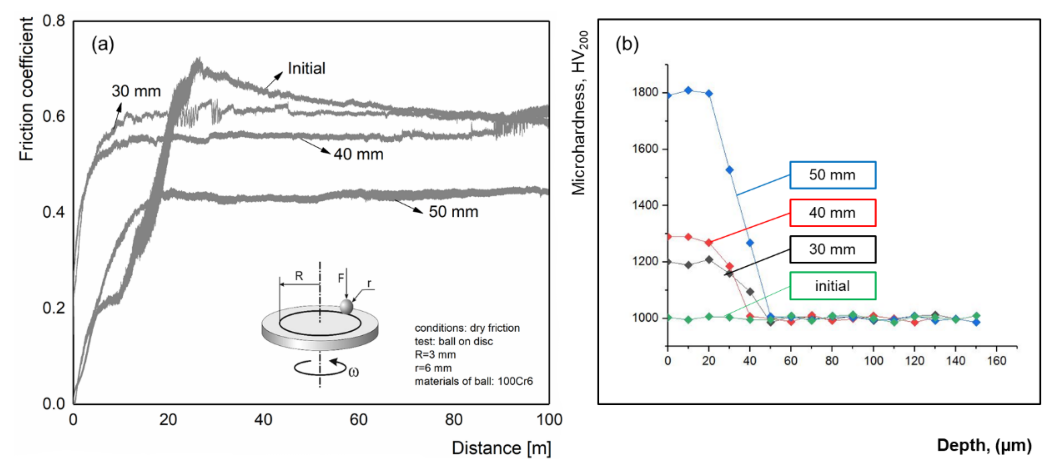
Figure 10a shows the curves of friction coefficient of Ti-Si-C coatings before and after modification by plasma treatment as a function of distance from the plasmatron. The study showed that the friction coefficient μ decreases after pulse-plasma treatment of the samples (
Figure 10a). If the value of the coefficient of friction in the initial coating Ti-Si-C is equal to 0.75, after pulse treatment, it decreases depending on the distance of H to 0.40 … 0.55. The conducted experiments showed that the pulse plasma treatment leads to an improvement in the tribological properties of Ti-Si-C coatings. This effect can be obtained due to the elimination of surface defects (microcracks and pores) and changes in the structural-phase state of the coatings (
Figure 5).
Hardness measurements across the cross-section of the surface layer are shown in
Figure 10b. Microhardness values were measured in three zones along the thickness of the cross-section of the coating, and the measurements corresponding to the transition zone were considered.
Figure 10b shows that the microhardness of the surface after PPT and the microhardness of the near-surface layers of the coatings are greater compared to the untreated coating. The thickness of the hardened layer (modified by the PPT method) is 20–30 microns. Subsequently, the microhardness decreases to 1000 HV and remains at the level of the microhardness value of the coatings before the PPT (in the initial state).
According to the results of XRD analysis, the increase in microhardness and wear resistance of detonation coatings of the Ti-Si-C system as a result of pulsed plasma treatment is associated with an increase in the Ti3SiC2 phase content in the coatings, as well as an increase in solid secondary phases or tungsten carbide (WC) particles.
4. Conclusions
The structural-phase state of the coatings after pulse-plasma treatment has been studied. Based on the analysis of the results of the study, the following conclusions can be made:
It was determined that after PPT, the intensity of Ti3SiC2 peaks increases and new reflexes appear (101, 102, 112, 204, 1110, 0016), which indicates an increase in MAX-phase content. The formation of carbide and oxide phases (WC and TiO2) in insignificant amounts is connected with the evaporation of the tungsten electrode during PPT in the air environment.
It was revealed that after PPT, the melting and alignment of structural elements of coatings without signs of the destruction of coatings from exposure to plasma pulses are observed. It was found that the microstructure of the coatings is a melted metal-ceramic material based on the Ti3SiC2 phase. The coating treated at a distance of 50 mm is characterized by an average lamella content and minimal porosity compared to the other modes of PPT.
It was found that the process of detonation sputtering followed by pulse-plasma treatment led to the formation of Ti3SiC2-based coating, with [00] carbosilicide (Ti3SiC2) plane reflections, lamellar layered structure and reduced porosity.
It is established that the microhardness of the coatings after the PPT increases in comparison with the coating before treatment, depending on the treatment distance. Values of the microhardness of the coatings after PPT processing at a distance of 50 mm increased up to ~1785 HV (before PPT ~1000 HV) at the expense of more effective formation of MAX phases.
It Is shown that before PPT, the average coefficient of the friction of coatings is ~0.60; after processing, the coefficient of friction decreases and is from 0.55 to 0.40 depending on the distance of processing. The reason for friction coefficient decrease can be an increase in microhardness and an increase in MAX-phase content in the coating’s composition. After PPT at a distance of 50 mm, the wear resistance of coatings to abrasion increases by 1.5–2.0 times.


 ,
, 


