Article

UV Durable LCOS for Laser Processing

1
SANTEC CORPORATION, 5823 Ohkusa-Nenjozaka, Komaki 485-0802, Japan
2
Department of Electrical Engineering, Faculty of Engineering, Sanyo-Onoda City University, Yamaguchi 756-0884, Japan
*
Author to whom correspondence should be addressed.
Crystals 2021, 11(9), 1047; https://doi.org/10.3390/cryst11091047
Submission received: 3 August 2021 / Revised: 24 August 2021 / Accepted: 24 August 2021 / Published: 30 August 2021
(This article belongs to the Special Issue Liquid Crystal Optics for Applications)

Abstract

:
Liquid-Crystal-On-Silicon (LCOS) Spatial Light Modulator (SLM) is widely used as a programmable adaptive optical element in many laser processing applications with various wavelength light sources. We report UV durable liquid-crystal-on-silicon spatial light modulators for one-shot laser material processing. Newly developed LCOS consists of UV transparent materials and shows a lifetime 480 times longer than the conventional one in 9.7 W/cm2 illumination at 355 nm. We investigated the durability of polymerization inhibitor mixed liquid crystal in order to extend its lifetime.

1. Introduction

Because conventional laser machining systems with one-way drawing use a 2-axis galvano mirror, they need a relatively long process time for fine large-area processing. Additionally, another mechanical actuator is needed to control depth direction on an optical axis for 3D processing. On the other hand, optical pattern forming technology allows for the generation of multiple beams or an arbitral 2D image with a computer generated hologram (CGH). Thus, high throughput and flexible processing can be realized by simultaneous multi-point scanning [1,2], one-shot 2D mask illumination or vertex beam generation, as shown in Figure 1. Spatial light modulators (SLMs) based on liquid-crystal-on-silicon (LCOS) are suitable candidates for generating the 2D optical mask, which works as both an optical phase modulator and an optical intensity modulator. It is difficult to create a CGH image with conventional techniques such as thin-film-transistor liquid crystal displays or digital mirror devices (DMD) because they have no ability of optical phase modulation and can only control optical intensity. Since LCOS can generate not only digital binary ON-OFF filters but also arbitral analog filters with a desired 2D space intensity profile, an unprecedented level of laser processing can be achieved by controlling the 3D space, including depth direction, rather than just the 2D plane [3,4,5]. The 1064 nm or 532 nm Nd:YAG lasers are widely used for laser processing techniques, including laser micromachining, laser printing and laser modification with a variety of materials, such as metals, dielectrics, polymers and semiconductors [6,7]. In general, the operational optical bandwidth of LCOS is limited from the visible (VIS) to the near-infrared (NIR) range, owing to an ultraviolet absorption of the constitutional materials; although some effective studies for liquid crystal devices under ultraviolet (UV) light have been reported [8,9,10,11]. However, there are so many interesting applications in the UV range [12,13,14], such as 3D printing, integrated circuit (IC) laser trimming, printed circuit board (PCB) cutting and maskless exposure. In this paper, we report a UV durable LCOS technology for LCOS based UV laser processing.

2. Materials and Methods

Figure 2 shows a typical schematic configuration of reflective type LCOS [15,16,17,18,19]. The LCOS generally comprises of a liquid crystal panel and a CMOS drive circuit. The liquid crystal panel has almost the same structure as conventional liquid crystal displays, which is the sandwich-like structure consisting of cover glass plate, liquid crystal (LC) and CMOS circuit backplane. Both the cover glass and the CMOS backplane have additional functional layers to control LC orientation, as shown in Figure 2.
LCOS technology was established to obtain the basis for display applications and success in cinema projectors and rear projection TVs. Thus, typical LCOS is designed on the condition of VIS light control, and the use of LCOS has been limited in the VIS to NIR region because of the UV absorption of the constituent materials, especially in cover glass plate, indium tin oxide (ITO) electrode, polyimide LC alignment layer, metal mirror/electrode and LC material. Actually, conventional LCOS is subjected to easily permanent, irreparable damage due to UV laser radiation or high power laser radiation, even in VIS or NIR light sources [20]. In order to extend LCOS applications to the UV region, we investigated the resistivity of the LCOS composed of UV transparent materials, fused-silica cover plate, a 15 nm thin ITO electrode, an inorganic SiOx alignment layer, a SiO2/SiN dielectric mirror on aluminum electrodes and a special blended nematic LC, which has an absorption edge wavelength (λg) shorter than 300 nm, as shown in Figure 3. The LC was consisted of a mixture of cyclohexane derivatives, having fluorine substitutes instead of a mixture of cyano group derivatives, which has been employed for visible applications in general. In addition, the LC contains none of the tolan derivatives, and the birefringence Δn is 0.08.
Figure 4 shows the measurement setup for evaluating the LCOS durability of UV laser illumination. The setup consists mainly of two lasers and LCOS. Laser 1 (λ = 355 nm) is for the power laser to evaluate LCOS optical durability and Laser 2 (λ = 532 nm) is for the probing laser to optically detect LCOS damage due to UV illumination. Both laser beams are illuminated in the same spatial position onto the LCOS panel after passing a thorough wire grid polarizer to ensure that each input polarization is linear and that the axis coincides with the longitudinal axis of LC molecules for optical phase modulation. A blazed phase grating was written to the LCOS to steer the incoming laser beam to the 1st order diffraction location in the far field by a specific voltage pattern applied to the electrodes. After passing the band-pass filter to block UV lasers, only the 1st order diffracted light of 532 nm probing laser is detected for the in-situ optical monitoring of LCOS damage. For splitting 0th and 1st order diffracted light, the laser beams were irradiated at 5 degrees to the LCOS.

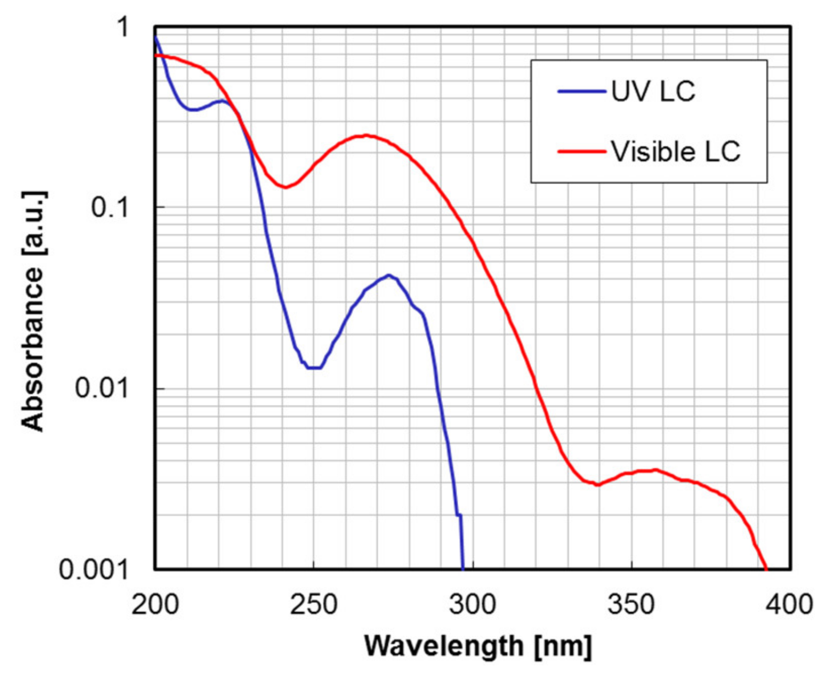
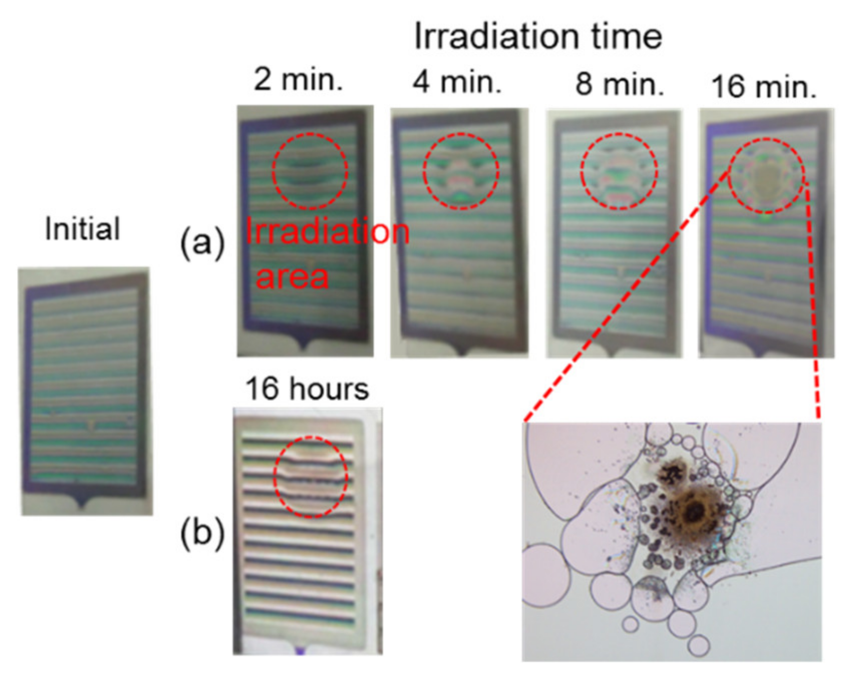
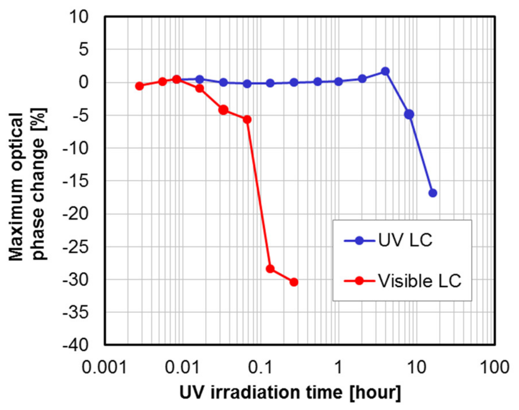
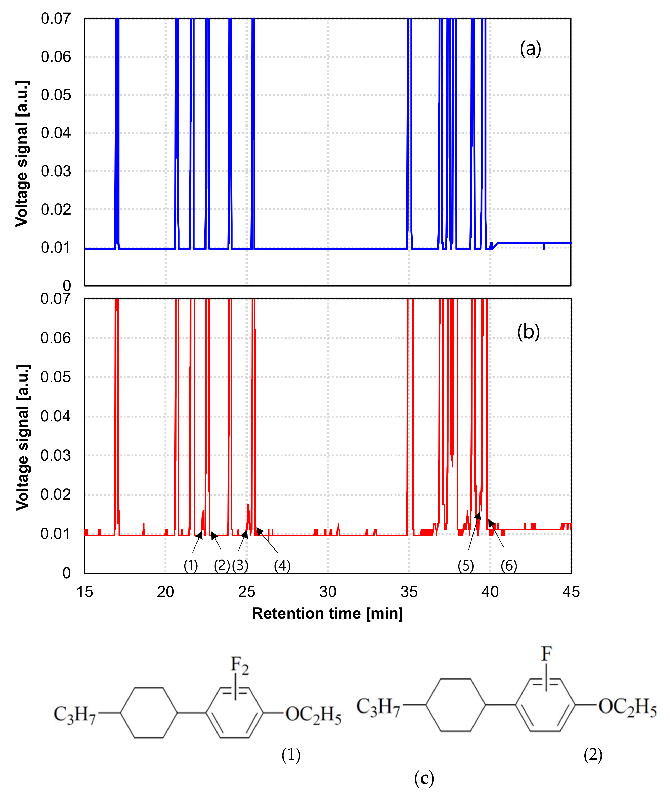
3. Results and Discussion

Figure 5 shows the comparison of UV resistivity between typical visible LCOS and UV LCOS. The power density and beam diameter of the irradiated UV laser was 9.7 W/cm2 and 6 mm, respectively. In visible LCOS, an abnormality in visual appearance was observed in an irradiation time of 2 min. On the other hand, similar abnormality was observed after 16 hours in UV-LCOS, which corresponds to 480 times higher resistivity.
We also measured the 1st order diffraction efficiency on a UV illuminated area, and the phase change due to UV irradiation was estimated, as shown in Figure 6. The optical phase change is calculated from measured diffraction efficiency by the following Equation (1), where η, Φ(x), Λ and m are the relative diffraction efficiency, phase shift function, grating period, and diffraction order number, respectively.
η = 1 Λ 0 Λ exp ( j Φ ( x ) ) × exp ( j 2 × π × m × x Λ ) d x 2
In LCOS, the maximum optical phase shift is limited by a LC thickness implicating optical response speed and fringing field effect [21,22,23]. Thus, a blazed grating for optical beam steering is represented by a modulo-2π (2π folded) sawtooth phase profile, and the phase shift function is expressed as a quantized multilevel step function due to the spatially pixelized mirror structure of LCOS [24,25,26]. Although a drastic improvement in lifetime was confirmed in UV LCOS, the phase degradation of about 15% in the irradiation time of 16 h was observed. LC is the only organic substance within UV LCOS materials on the light path and has the lowest resistance. Thus, we speculate that the observed degradation results from LC damage by UV radiation. For finding the true root cause of the damage, material content analysis by Gas Chromatography-Mass Spectrometry (GC-MS) (Agilent Technologies, Inc., Santa Clara, CA, USA) analysis was conducted, and the impurities contained in normal LC and damaged LC due to UV irradiation were compared, as shown in Figure 7. Due to its defluorinated compound close to the signal peak from the original chemical compound, multiple signals were detected from the damaged LC. The peak (1) is the one for the compound produced by the UV radiation in the damaged liquid crystal. The compound is considered to be formed by extracting fluoro atom from the original compound represented by the peak (2). Similarly, the peaks (3) and (5) are considered to be the ones for the compounds formed by the fluoro atom extraction from the original compounds shown by the peak (4) and (6). These results show that the damaged liquid crystal contains the compounds formed by fluoro atom extraction from the original compounds.
It is considered that the fluorine extracted compounds were formed by the cleavage of the C-F bond and radical formation. These results should also suggest the possibility that the formed radical species could decompose the liquid crystal compounds and induce the polymerization reaction. In order to verify the assumption, the laser durability of the LC blended phenolic polymerization inhibitor (2,6-Di-tert-butyl-p-cresol) was investigated with various mixed ratio, as shown in Figure 8. The power density and beam diameter of the irradiated CW laser (λc = 450 nm) are 30 W/cm2 and 1 mm, respectively. The lifetime was determined by the time when permanent visible damage was observed. With an increase of inhibitor concentration, the lifetime was extended drastically, although the nematic-isotropic phase transition temperature (TNI) decreased linearly. In addition, a significant change in the viscosity of the mixed LC was not observed in the experiment range. A 30-times longer lifetime was confirmed in the LC of 6 wt% inhibitor concentration compared to the normal LC without the inhibitor. At this moment, it is impossible to identify which LC mixtures in Figure 7 were stabilized by inducing polymerization inhibitors, but it might be clarified after GC-MS analysis of the damaged LC and the comparison of the damaged LC without polymerization inhibitors. It is expected that the polymerization inhibitor mixing technique is an effective means to expand the lifetime, even in UV light operation, and that it achieves further improvement by the deployment of a more effective polymerization inhibitor with optimum concentration.

4. Conclusions

We reported UV durable LCOS structures for one-shot laser processing. We observed higher UV resistivity in a UV LCOS composed of UV transparent materials compared to a typical visible LCOS. In addition, we showed that special blended liquid crystal with a polymerization inhibitor has the potential to drastically extend LCOS lifetime under UV operation. We believe that the proposed concept will open up a new class of laser processing.

Author Contributions

Methodology, Y.S., M.N., M.I. and K.T.; writing—original draft preparation, Y.S.; writing—review and editing, K.T.; supervision, K.T. All authors have read and agreed to the published version of the manuscript.

Funding

This research received no external funding.

Conflicts of Interest

The authors declare no conflict of interest.

References

  1. Hayasaki, Y.; Sugimoto, T.; Takita, A.; Nihsida, N. N. Variable holographic femtosecond laser processing by use of a spatial light modulator. Appl. Phys. Lett. 2005, 87, 031101. [Google Scholar] [CrossRef]
  2. Matsumoto, N.; Itoh, H.; Inoue, T.; Otsu, T.; Toyoda, H. Stable and flexible multiple spot pattern generation using LCOS spatial light modulator. Opt. Express 2014, 22, 24723–24733. [Google Scholar] [CrossRef] [PubMed]
  3. Hasegawa, S.; Hayasaki, Y. Dynamic control of spatial wavelength dispersion in holographic femtosecond laser processing. Opt. Lett. 2014, 39, 478–481. [Google Scholar] [CrossRef]
  4. Matthieu, B.; Arnaud, R.; Bruno, B.; Kevin, B.; Mona, T.; Thierry, C.; Martin, R.; Lionel, C. Beat the diffraction limit in 3D direct laser writing in photosensitive glass. Opt. Express 2009, 17, 10304–10318. [Google Scholar]
  5. Gian-Luca, R.; Cemal, E.; Ralf, H. Femtosecond laser direct generation of 3D-microfluidic channels inside bulk PMMA. Opt. Express 2017, 25, 18442–18450. [Google Scholar]
  6. Sakurai, Y.; Hotta, Y.; Ottowa, R.; Nishitateno, M.; Zheng, L.; Yamamoto, H.; Taira, T. One-shot 3D giant-pulse micro-laser processing by LCOS direct control. Joint Session LIC+PLD+SLPC. In Proceedings of the 6th Laser Ignition Conference 2018, OPTICS & PHOTONICS International Congress 2018, Yokohama, Japan, 23–27 April 2018. [Google Scholar]
  7. Bhandari, R.; Taira, T. >6 MW peak power at 532 nm from passively Q-switched ND:YAG/Cr4+:YAG microchip laser. Opt. Express 2013, 19, 19135–19141. [Google Scholar] [CrossRef] [PubMed]
  8. Wu, S.T.; Ramos, E. Polarized UV spectroscopy of conjugated liquid crystals. J. Appl. Phys. 1990, 68, 78–85. [Google Scholar] [CrossRef]
  9. Wu, S.T. Absorption measurements of liquid crystals in the ultraviolet, visible, and infrared. J. Appl. Phys. 1998, 84, 4462–4465. [Google Scholar] [CrossRef]
  10. Wen, C.H.; Gauza, S.; Wu, S.T. Photostability of liquid crystals and alignment layers. J. Soc. Inf. Disp. 2005, 13, 805–811. [Google Scholar] [CrossRef]
  11. Yang, Q.; Zou, J.; Li, Y.; Wu, S.T. Fast-response liquid crystal phase modulators with an excellent photostability. Crystals 2020, 10, 765. [Google Scholar] [CrossRef]
  12. Hansen, W.W.; Janson, S.W.; Helvajian, H. Direct-write UV laser microfabrication of 3D structures in lithium aluminosilicate glass. In Laser Applications in Microelectronic and Optoelectronic Manufacturing II; International Society for Optics and Photonics: Bellingham, WA, USA, 1997; Volume 2991, pp. 104–112. [Google Scholar]
  13. Antoszewski, B.; Tofil, S.; Mulczyk, K. The efficiency of UV picosecond laser processing in the shaping of surface on elastomers. Polymers 2020, 12, 2041. [Google Scholar] [CrossRef] [PubMed]
  14. Ligon, S.C.; Blugan, G.; Kuebler, J. Pulsed UV laser processing of carbosilane and silazane polymers. Materials 2019, 12, 372. [Google Scholar] [CrossRef] [PubMed] [Green Version]
  15. Zhang, Z.; You, Z.; Chu, D. Fundamentals pf phase-only liquid crystal on silicon (LCOS) devices. Light Sci. Appl. 2014, 3, e213. [Google Scholar] [CrossRef]
  16. Bleha, W.P.; Lei, L.A. Advances in liquid crystal on silicon (LCoS) spatial light modulator technology. In Display Technologies and Applications for Defense, Security, and Avionics VII; International Society for Optics and Photonics: Bellingham, WA, USA, 2013; Volume 8736, p. 87360A. [Google Scholar]
  17. Bauchert, K.; Serati, S.; Furman, A. Advances in liquid crystal spatial light modulators. In Optical Pattern Recognition XIII; International Society for Optics and Photonics: Bellingham, WA, USA, 2002; Volume 4734, pp. 35–43. [Google Scholar]
  18. Vettese, D. Liquid crystal on silicon. Nat. Photonics 2010, 4, 752–754. [Google Scholar] [CrossRef]
  19. McManamon, P.F.; Watson, E.A.; Dorschner, T.A.; Barners, L.J. Applications look at the use of liquid crystal writable gratings for steering passive radiation. Opt. Eng. 1993, 32, 2657–2664. [Google Scholar] [CrossRef]
  20. Carbajo, S.; Bauchert, K. Power handling for LCoS spatial light modulators. In Laser Resonators, Microresonators, and Beam Control XX; International Society for Optics and Photonics: Bellingham, WA, USA, 2018; Volume 10518, p. 105181R. [Google Scholar]
  21. Kelly, J. Application of liquid crystal technology to telecommunication devices. In National Fiber Optic Engineers Conference; Optical Society of America: Washington, DC, USA, 2006; p. NThE1. [Google Scholar]
  22. Apter, B.; Efron, U.; BahatTreidel, E. On the fringing-field effect in liquid-crystal beam-steering devices. Appl. Opt. 2004, 43, 11–19. [Google Scholar] [CrossRef] [PubMed]
  23. FanChiang, K.H.; Wu, S.T.; Chen, S.H. Fringing-field effects on high-resolution liquid crystal microdisplays. J. Disp. Technol. 2005, 1, 304–313. [Google Scholar] [CrossRef]
  24. Serati, S.; Stockley, J. Advanced liquid crystal on silicon optical phase arrays. In Proceedings of the IEEE Conference on Aerospace, Big Sky, MT, USA, 9–16 March 2002. [Google Scholar]
  25. Lensina, A.C.; Goodwill, D.; Bernier, E.; Ramunno, L.; Berini, P. On the performance of optical phased array technology for beam steering: Effect of pixel limitations. Opt. Express 2020, 21, 31637–31657. [Google Scholar]
  26. McManamon, P.F.; Dorschner, T.A.; Corkum, D.L.; Friedman, L.J.; Hobbs, D.S.; Holz, M.; Liberman, S.; Nguyen, H.Q.; Resler, D.P.; Sharp, R.C.; et al. Optical phase array technology. Proc. IEEE 1996, 84, 268–298. [Google Scholar] [CrossRef]
Figure 1. Schematic comparison of laser processing systems. (a) Conventional system with a 2-axis scanner and (b) one-shot 3D system.
Crystals 11 01047 g001
Figure 2. Schematic drawing of typical LCOS layer structure.
Crystals 11 01047 g002
Figure 3. Comparison of the liquid crystal absorption spectrum between the typical visible liquid crystal (LC) and the special blended LC for high UV resistivity. The birefringence Δn for UV LC and visible LC was 0.08 and 0.20 at 589 nm, respectively. Each LC was dissolved in cyclohexane solvent with 20 mg/L concentration and filled into a 1 cm long silica glass cell for spectroscopic measurement.
Crystals 11 01047 g003
Figure 4. Optical setup for evaluating the UV laser durability of LCOS.
Crystals 11 01047 g004
Figure 5. UV resistivity of LCOS with (a) typical visible LC and (b) special blended LC for high UV resistivity. Each cell gap of the LCOS panels for visible LC and UV durable LC is 9.7 μm and 6.0 μm, respectively.
Crystals 11 01047 g005
Figure 6. Maximum phase retardation on the UV irradiated area of LCOS with typical visible LC and special blended LC for high UV resistivity.
Crystals 11 01047 g006
Figure 7. Measured GC/MS spectra. (a) normal liquid crystal without UV irradiation and (b) damaged liquid crystal with UV irradiation. (1)(2), (3)(4) and (5)(6) are pairs of the original base compound of the liquid crystal and its defluorinated compound, respectively. (c) shows a putative compound structure of (1) and (2) in the GC/MS spectrum.
Crystals 11 01047 g007
Figure 8. Measured lifetime and nematic-isotropic phase transition temperature of liquid crystal blended with various concentrations of polymerization inhibitors. The lifetime is defined as the time between the laser power turning on and visible permanent damage.
Crystals 11 01047 g008
Publisher’s Note: MDPI stays neutral with regard to jurisdictional claims in published maps and institutional affiliations.

