Article

Crystal Plasticity with Micromorphic Regularization in Assessing Scale Dependent Deformation of Polycrystalline Doped Copper Alloys

Integrated Computational Materials Engineering, VTT Technical Research Centre of Finland Ltd., 02044 Espoo, Finland
*
Author to whom correspondence should be addressed.
Crystals 2021, 11(8), 994; https://doi.org/10.3390/cryst11080994
Submission received: 8 July 2021 / Revised: 9 August 2021 / Accepted: 19 August 2021 / Published: 21 August 2021
(This article belongs to the Special Issue Micromechanical Modelling and Its Applications to Polycrystals)

Abstract

:
It is planned that doped copper overpacks will be utilized in the spent nuclear fuel repositories in Finland and in Sweden. The assessment of long-term integrity of the material is a matter of importance. Grain structure variations, segregation and any possible manufacturing defects in microstructure are relevant in terms of susceptibility to creep and damage from the loading evolution imposed by its operating environment. This work focuses on studying the microstructure level length-scale dependent deformation behavior of the material, of particular significance with respect to accumulation of plasticity over the extensive operational period of the overpacks. The reduced micromorphic crystal plasticity model, which is similar to strain gradient models, is used in this investigation. Firstly, the model’s size dependent plasticity effects are evaluated. Secondly, different microstructural aggregates presenting overpack sections are analyzed. Grain size dependent hardening responses, i.e., Hall-Petch like behavior, can be achieved with the enhanced hardening associated with the micromorphic model at polycrystalline level. It was found that the nominally large grain size in the base material of the overpack shows lower strain hardening potential than the fine grained region of the welded microstructure with stronger strain gradient related hardening effects. Size dependent regularization of strain localization networks is indicated as a desired characteristic of the model. The findings can be utilized to provide an improved basis for modeling the viscoplastic deformation behavior of the studied copper alloy and to assess the microstructural origins of any integrity concerns explicitly by way of full field modeling.

1. Introduction

Regarding the spent nuclear fuel repository in Finland, the copper overpack of the canister will be an important barrier against radioactive discharge from the repository. Final disposal overpacks are placed in a cave in bedrock at a depth of approximately 400 m [1]. The overpack is surrounded by bentonite blocks that swell due to the ground water. As the hydrostatic and bentonite swelling pressure developed the overpack will be pressed against the insert, affecting the stress state in the overpack. High purity oxygen-free phosphorus-doped (OFP) copper is the intended material for the overpack to reduce the amount of Cu 2 O inclusions. The phosphorous is added to further reduce the inclusion since as the hydrogen diffuses through the copper it can react with the Cu 2 O inclusions, forming H 2 O steam bubbles at the grain boundaries. The overpack will be internally heated up to 100 °C by residual nuclear fuel activity and thus time-dependent deformation and damage mechanisms (creep, stress relaxation and cyclic loads) are active during its operational lifetime.
The creep behavior of OFP copper has been extensively studied over the years due to the immediate concern to ensure integrity in the final disposal applications. These works have focused on both the experimental campaigns and the development of modeling and integrity analysis methods, as in, for example, [2,3]. Typically, the respective works have not explicitly treated material plasticity and creep at the scale of the microstructure, but rather presented “top-down”-like approaches to assess the behavior of bulk material and discontinuities such as welds and focused on extrapolation of the experimental results towards long-term operational periods. Simultaneously, strategies have been developed to better integrate more complex creep models to integrity analyses [4,5] to account for different stages of creep (such as extensive primary creep exhibited by several relevant copper alloys [3]) and effects of joints and welds via concepts such as the weld strength factor (WSF). However, none of these nor other earlier works have performed direct modeling of plasticity at the scale of the microstructure, but rather have identified the possible need to further the respective capabilities to improve upon the respective predictive nature of the used material models and approach them in a somewhat more physics-based manner.
Micromechanical modelling, on the other hand, provides the basis for microstructure informed modelling of creep incorporating plastic deformation (slip) and the damage (cumulative microstructure scale creep-fatigue damage). In current work, microstructural and crystal plasticity (CP) modelling of OFP copper is utilized and its performance in reproducing experimentally determined stress and strain responses is presented. CP models can be employed to investigate microscale deformation, hardening and eventually susceptibility to damage. To address the grain size dependencies of the material, often a Hall-Petch type relation is introduced in the models, which defines yield offset to match grain size dependent yielding behavior and link grain size with the evolution of dislocation density [6]. Alternatively, length-scale dependent plasticity models can be utilized [7,8]. Constitutive relations are modified to represent storage of geometrically necessary dislocations (GND) within a crystal plasticity framework [9,10]. With the use of a full dislocation density tensor it is possible to capture size effects at the level of microstructure to analyze grain–grain interactions or the role of defects [11,12]. Similar size dependent effects are obtainable with micromrphic theory originally proposed in [13,14] and further developed in [15]. Besides size dependent hardening behavior, the regularization of strain localization is the key target of these models and the associated softening in the shear bands. Current work does not directly account for damage accumulation at the scale of the material microstructure, although this is a direct extension of the proposed approach also in the case of OFP copper alloys [16], and is predicted to improve upon the capabilities in assessing the interactions between plasticity and defect structures especially critical in welds of the overpack structure.
This work uses a reduced micromorphic model with a scalar variable linked to strain gradient effects, which is introduced in Section 2. Such models have been developed in the past [17,18,19] to reduce the computational cost of the length-scale dependent models. As a novel feature, we investigate the deformation and strain hardening behavior of the copper overpack material at the polycrystalline level. The microstructure of the material varies depending on the section of the cylindrical shaped overpack, on whether the base material of the cylinder/lid parts are analyzed or on whether the friction stir welded zone is a matter of interest. Results are divided into two main topics. Section 3.2 focuses on the scaling capability of the micromorphic model with electron back-scatter diffraction (EBSD) based realistic microstructural aggregates. In Section 3.3, which includes final results, we perform simulated tensile tests concerning the different overpack microstructures to analyze strain hardening, stress and strain localization behavior. The role of the enhanced hardening model is discussed and observations on the relevant plastic deformation behavior of the investigated microstructures are provided.

2. Materials and Methods

Crystal Plasticity Modeling

A crystal plasticity model is employed in this work to analyze microstructure level deformation behavior. The model is implemented in finite element software Z-set [20,21]. A finite strain formalism is used with a multiplicatively decomposed deformation gradient to elastic and plastic parts:
F ̲ = F ̲ E · F ̲ P
Dislocation slip rate is given by a viscoplastic flow rule. Dislocation driven plasticity occurs by a sum of potentially active twelve { 111 } < 110 > slip systems, given by:
γ ˙ s = | τ s | ( R s S χ ) K N s i g n ( τ s )
where K and N describe viscosity and strain rate dependency, respectively. τ s is the resolved shear stress on a slip system s computed with τ s = C ̲ e · ( Λ ̲ ̲ : E ̲ G L e ) . C ̲ e is the Cauchy–Green tensor, Λ ̲ ̲ is the elastic stiffness tensor, and E ̲ G L e is the Green–Lagrange strain tensor, E ̲ G L e = 1 / 2 ( F ̲ E T · F ̲ E I ̲ ) . A conventional isotropic hardening contribution is defined by R s . The generalized stress S χ provides another source of isotropic hardening for the slip system. The theoretical and thermodynamic derivation of the strain gradient extension S χ is provided in Reference [18]. An alternative formulation of a similar kind of strain gradient extension using a so-called augmented Lagrangian method can be found in [22]. The key aspect of the present reduced Micromorphic strain gradient model is essentially to provide scale dependent regularization on a plastic slip. This characteristically provides scale dependent hardening behavior, which we employ in this work to further the realism in modeling polycrystalline OFP copper microstructures. The major difference in this work is that we investigate the model behavior for polycrystalline copper, while the referred-to previous studies focused on the regularization of local slip bands as well as on the model’s characteristics and effects of micromorphic parameters.
Regularization of slip is established with an additional strain-like scalar variable microslip, γ χ , introduced as a degree of freedom (DOF) [18] in addition to the standard displacement DOFs, i.e., DOF = {u, γ χ }. The Lagrangian gradients of the degress of freedom are
H ̲ ( x , t ) = u X = G r a d ( u ) a n d K ( x , t ) = γ χ X = G r a d ( γ χ )
where H ̲ is the displacement gradient related to the deformation gradient F ̲ by F ̲ = 1 ̲ + H ̲ and the extended part K is considered as a Lagrangian microslip gradient vector. The following stresses are generally introduced [19]:
S ̲ = ρ 0 ρ σ ̲ · F ̲ T
M = ρ 0 ρ F ̲ 1 · m
S = ρ 0 ρ s
where S ̲ is the first Piola–Kirchoff stress which generates mechanical power with F ˙ ̲ and Cauchy stress tensor σ with F ˙ ̲ · F ̲ 1 . Two vectors M and m are generalized stresses in reference and current configurations, respectively. Similarly, scalar generalized stresses S and s generate power with γ χ ˙ . The conventional principle of virtual power is extended to higher order contributions. The contributions of γ χ and K χ , of which there are energetic counterparts, are the scalar stress S and vector stress M .
The free energy function is chosen as follows. The isotropic and quadratic form is also chosen for gradient K contribution in the present work, which leads to the use of a single higher order modulus A. If the penalization parameter H χ is chosen high enough, the micromorphic model extension in fact resembles classical strain gradient plasticity [23]. In such a case, γ χ becomes almost equal to γ c u m .
ψ ( E ̲ G L e , ρ s , γ c u m , γ χ , K χ ) = 1 2 ρ E ̲ G L e : C ̲ ̲ : E ̲ G L e + ψ h ( ρ s ) + A 2 ρ 0 K χ . K χ + H χ 2 ρ 0 ( γ c u m γ χ ) 2
ρ and ρ 0 denote the volumetric mass density in the intermediate and initial configurations, respectively. ψ h ( ρ s ) is a hardening potential that can have different forms depending on the chosen dislocation model. Then the state laws are postulated according to the Colleman–Noll procedure.
Π ̲ e = ρ ψ E ̲ G L e = C ̲ ̲ : E ̲ G L e
S = ρ 0 ψ γ χ = H χ ( γ c u m γ χ )
M = ρ 0 ψ K χ = A K χ
A cumulative plastic slip term γ c u m is defined as:
γ c u m = 0 t s N s | γ ˙ s | d t
Then the plastic slip defines γ c u m and the residual mechanical dissipation can hence be written
d = s = 1 N s ( | τ s | + ρ ρ 0 S ) | γ ˙ s | ρ ψ h ρ s ρ ˙ s
The modified flow rule f s expressed in Equation (2) can also be written by:
f s = | τ s | ( R s S χ ) = | τ s | ( R s A D i v ( G r a d γ χ ) ) = | τ s | ( R s A Δ χ γ χ )
γ c u m and microslip γ χ are related by a regularization equation [18]:
γ χ A H χ Δ χ γ χ = γ c u m
where Δ χ is Lagrangian–Laplace type operator. Micromorphic parameters A and H χ control the gradient effect. Their more detailed meaning and influence on slip localization are discussed in [19]. In summary, it can then be derived that the generalized stress, denoted hereafter by S χ , affecting slip activity is:
S χ = H χ ( γ c u m γ χ )
The classical isotropic hardening related to Hall-Petch behavior and dislocation interactions is given by:
R s = τ H P + μ s = 1 N s a s r ρ r
where μ is the shear modulus, a s r is the dislocation interaction matrix, ρ r is the dislocation density of a system r and τ H P is a Hall-Petch term to be defined in the following.
In order to produce an increase in the yield stress, a common Hall-Petch yield offset is introduced. The strain gradient model evokes scale dependent material behavior once plastic strain begins to accumulate. Therefore, the initial yield condition depends on the assigned initial dislocation density and the offsetting given by the Hall-Petch term. In Section 3.2, we study the stress–strain response of the material with and without the Hall-Petch offset condition to show the hardening response associated with the length-scale:
τ H P = μ μ r e f K H P d
where μ r e f is the reference value for shear modulus at room temperature and μ is the current shear modulus value at a specific temperature. The Hall-Petch coefficient is K H P and the average grain size is d. We assume that solid solution strengthening is included in the Hall-Petch term and we do not introduce it separately.
The evolution of dislocation density is given by:
ρ ˙ s = | γ s ˙ | ( s = 1 N s a s r ρ r K o b s G c ρ s )
where parameter K o b s describes the strength of obstacles immobilizing dislocations and defines the strain hardening curvature. Parameter G c controls the dislocation annihilation process.

3. Results and Discussion

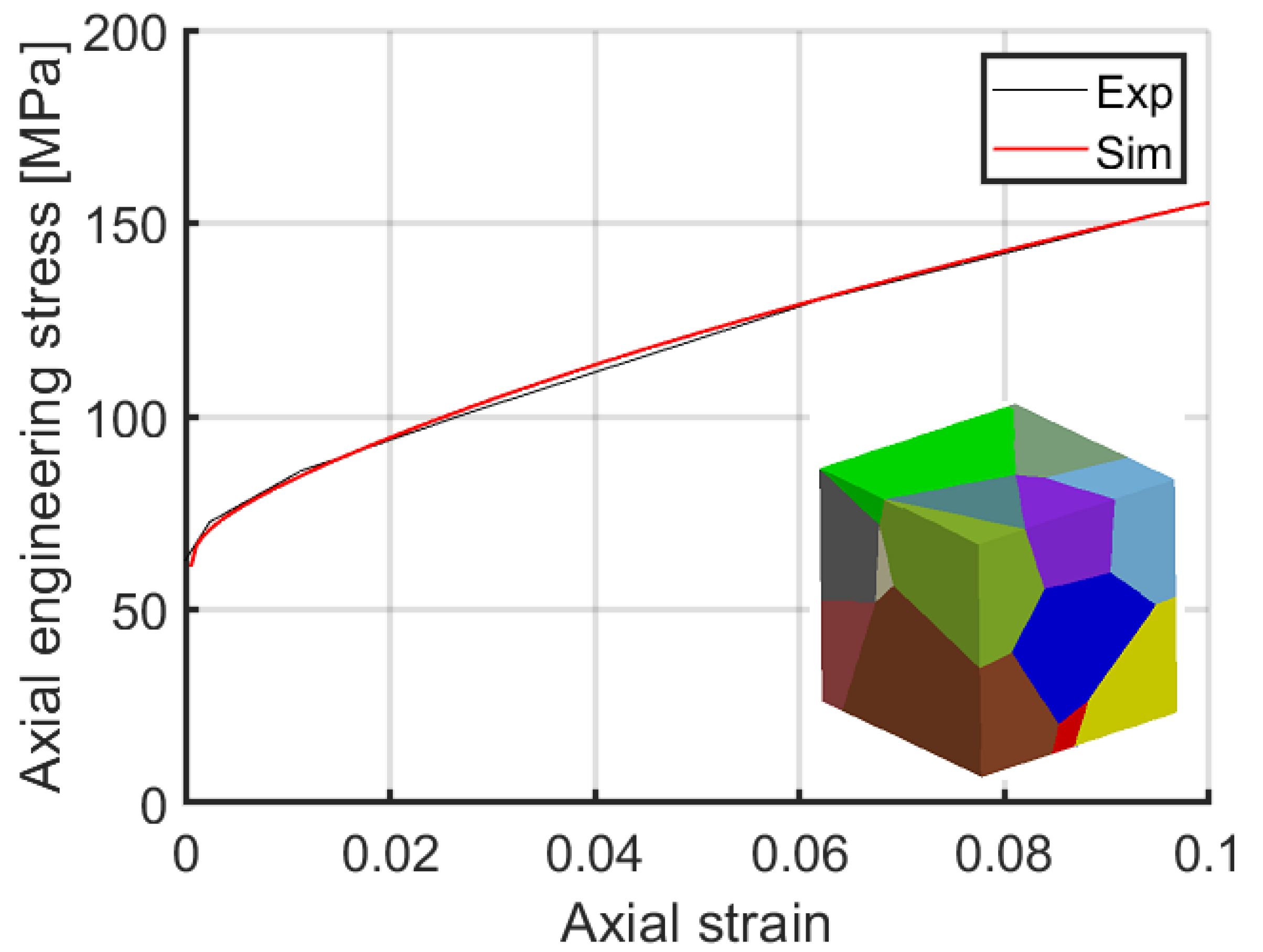
3.1. Material Model Parameters

The single crystal model parameters were fitted with available experimental data curves from Reference [24] at 75 °C, first using a simplified 3D microstructural aggregate with a small amount of grains with random orientation for computational efficiency. The small 3D RVE does not have a sufficient amount of grains or orientations for a representative fit. Therefore the parameters were verified with realistic grain structures in Section 3.3. Figure 1 shows simulated and experimental stress–strain curves after parameter identification. Table 1 lists the simulation parameters for the model.

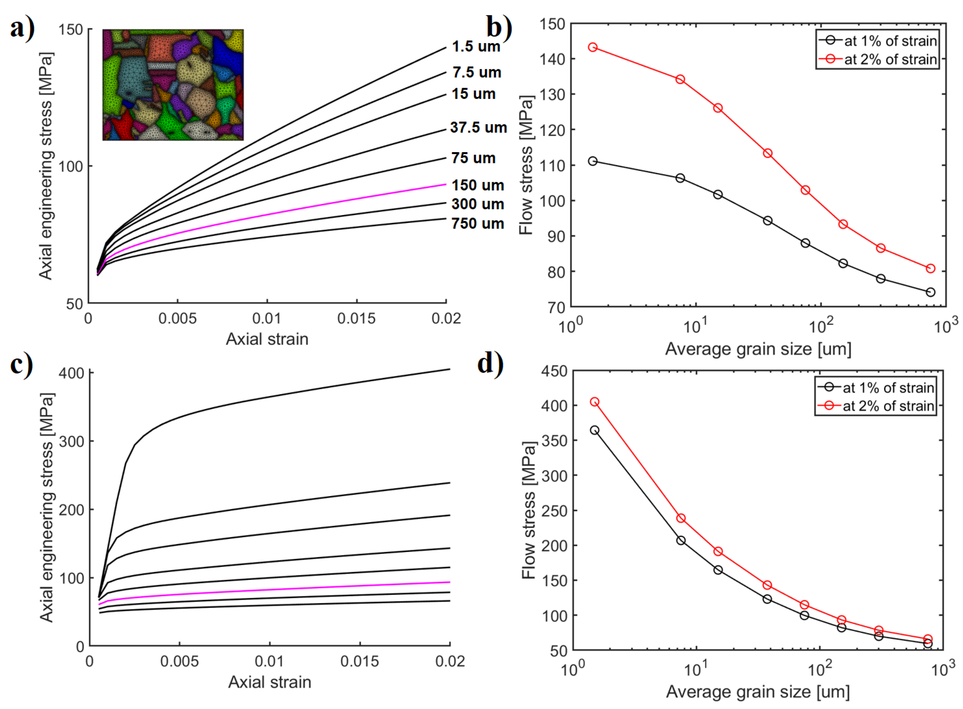
3.2. Model Scaling Effect

To analyze the grain size scaling effects of the model, tensile tests were simulated up to 2% of strain using a subset of an EBSD map as a computational domain. The EBSD map is extruded to one element thickness. The left side of the domain is fixed in a horizontal direction (U1 = 0) and the bottom of the domain is fixed in a vertical direction (U2 = 0). Displacement is subjected to the right side of the domain to produce deformation and the top side of the domain is constrained with multi-point constrain so that it remains straight during deformation. Both the back and the front sides of the domain are constrained with U3 = 0. Grain boundaries are not explictely modeled and continuity of displacement and microslip degrees of freedom are considered. The RVE was scaled to yield different grain sizes for the analysis. Grain size of 150 μ m is considered a reference. The range of grain sizes is selected based on those observed in base OFP copper alloys as well as weldments, see, for example, [3].
Figure 2a,c show stress–strain curves for the chosen grain sizes. In Figure 2a, the initial dislocation density was set equal for each case. The Hall-Petch offset was taken to have a constant value based on 150 μ m grain size, which means that no additional offset is included even when the grain size decreases to analyze the effect of the present gradient plasticity extension. Both Figure 2a,b show that the length-scale effects become important already in the microplasticity regime after yielding with a notable influence on the strain hardening rate already at very low strains. This is also the reason for the apparent increase in yield stress seen in Figure 2a even without the additional Hall-Petch term. Figure 2b shows that the size dependent effects tend to saturate at very small and large grain sizes producing the tanh-type of curvature observed in the figure. This behavior is a typical characteristic of the micromorphic crystal plasticity models [26] which have a finite hardening response.

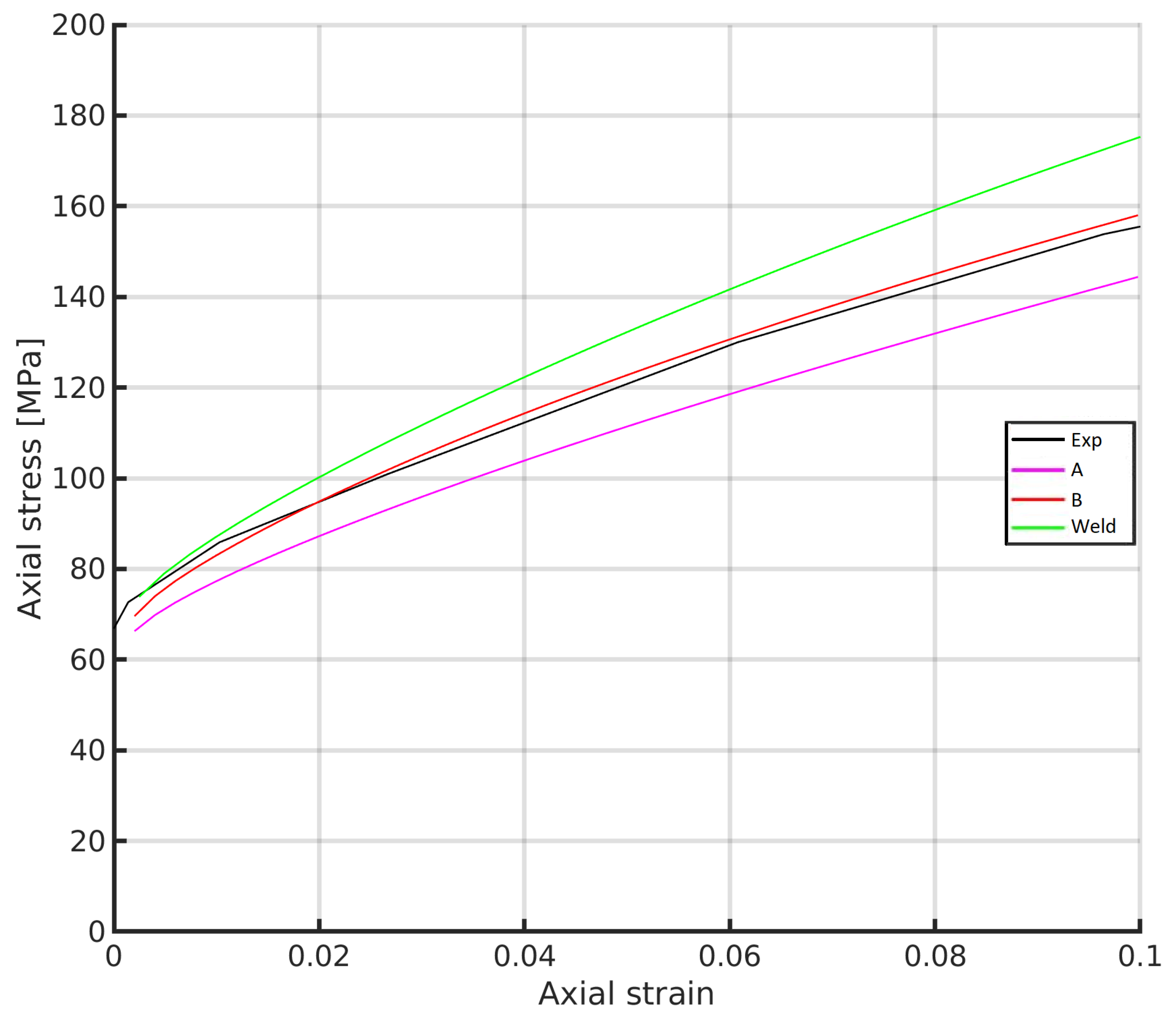
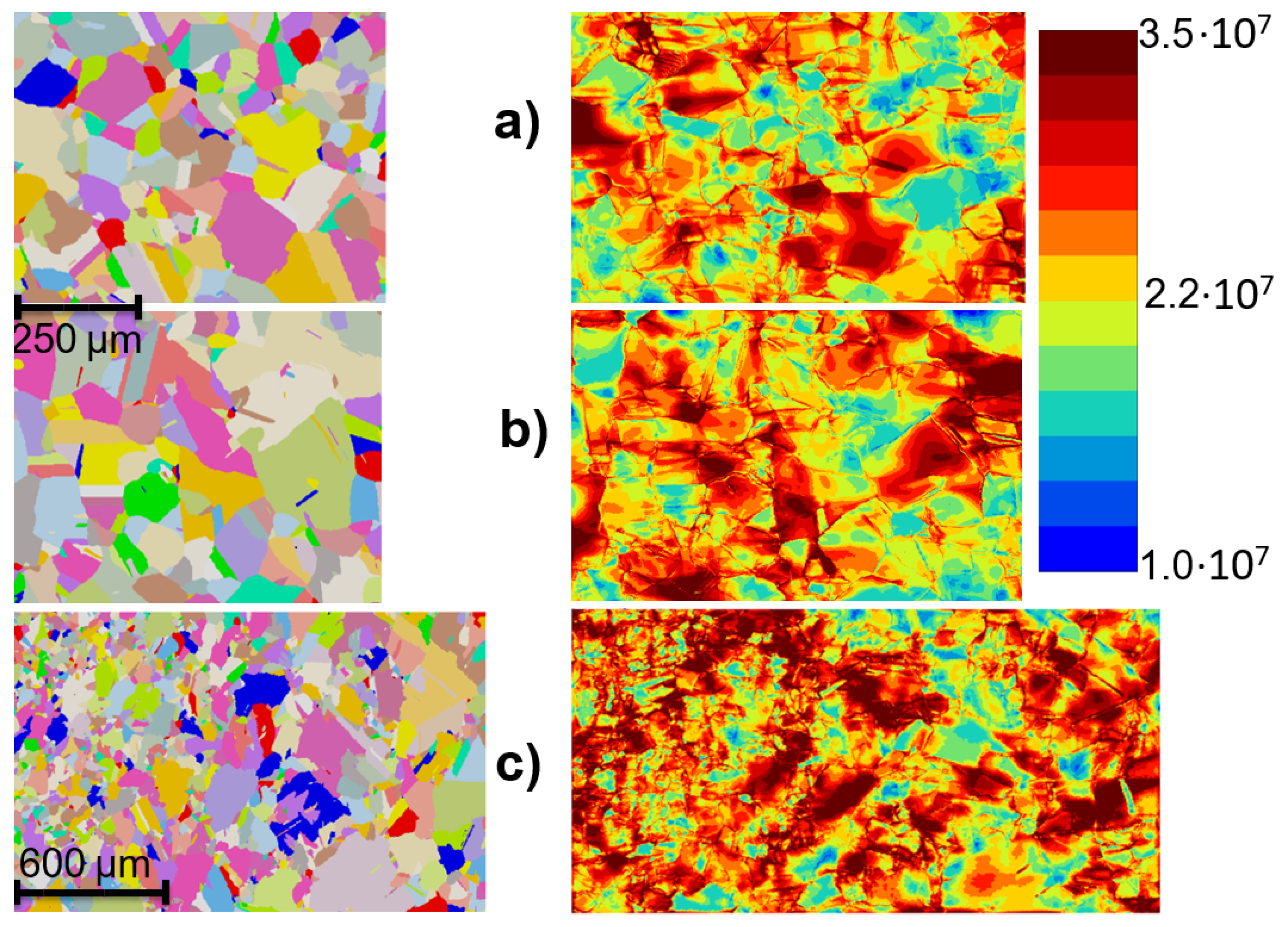
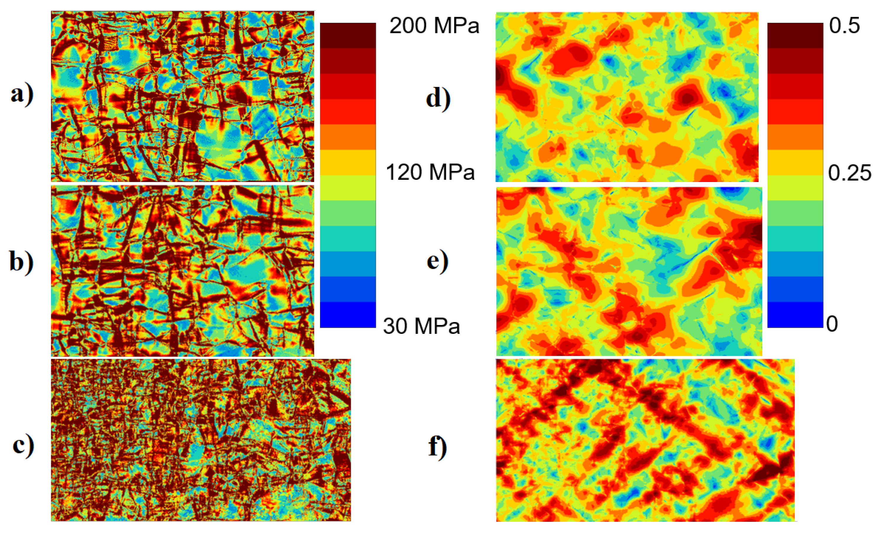
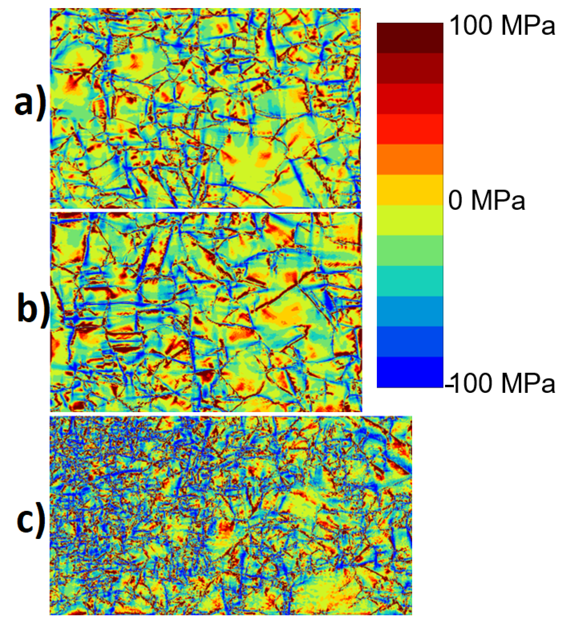
3.3. Simulation of Copper Canister Microstructure Deformation

The copper overpack material has different microstructural zones depending on the materials processed during manufacturing. Grain size varies depending on the section in the canister and whether the material is welded at some locations. Tensile simulations were performed on three chosen microstructures. Microstructure A is located within the cylindrical section of the overpack, while B is extracted from the lid section of the overpack. In general, the microstructures are quite similar between A and B, containing a mixture of small and large grains. Additionally, a friction stir welded zone was included as a separate simulation since it contains a finer grain size distribution with gradient like refinement in size in the chosen computational domain. It is noteworthy that the welded microstructure can contain this type of refined grain size or alternatively enlarged grain size in some sections of the material, the mismatch of which, with respect to resulting viscoplastic strain rates, is one additional source for concern and where more detailed modeling tools are required. Additionally, we focus on the small grain size case due to the assumption that it has a higher probability to generate high stress concentrations due to the scale dependency. This aspect is also important when analysing the model response with respect to finer grain sizes. The used computational microstructures are shown in Figure 4.
For the A and B cases, we assumed the same average initial grain size of 150 μ m and for the friction stir welded zone 102 μ m was used. This choice affects the initial Hall-Petch yield offset in the stress–strain curves. Figure 3 shows the stress–strain response of the microstructure cases. It can be seen that the Hall-Petch offset associated differences appear relatively small because the average initial grain size does not have such high variation. The simulated stress–strain curves of microstructure B describe the experimentally obtained strain hardening behavior well.
Figure 5 shows von Mises stress and cumulative plastic slip at 10% of strain. Inhomogeneous von Mises stress distributions are observed with highest magnitudes at the grain boundaries. Their magnitude tends to decrease towards the cores of the large grains. Smaller grains generate higher stress fields populating almost whole individual grains. For this reason, the welded microstructure shows stronger strain hardening due to the finer overall grain size within the microstructural aggregate. In spite of the microstructures of A and B being quite similar, the hardening responses are slightly different. Microstructure B tends to develop strain localization networks that increase the local dislocation density. The developed strain gradients promote the increase in the generalized stress term affecting the hardening response. This becomes apparent later in Figure 6. Microstructure B shows more of the possible annealing twins and/or parts of other grains in in-depth directions than microstructure A. This causes an orientation change within the large grains and promotes both increase in dislocation density and the additional gradient type hardening.
The welded microstructure develops more distinctive inter-grain continuous cumulative plastic slip zones than the A and B microstructures. This result is in line with the observations made by Cordero et al. [26] with a model using the full curl of the plastic deformation tensor, i.e., the so-called microcurl model. When the grain size decreases, the accumulated slip tends to progressively build finite sized strain localization bands until it becomes energetically too expensive at very small grain sizes. At the same time, the scale dependent hardening effectively increases the flow stress which we observe as stronger strain hardening.
Total dislocation density is plotted at an integration point level in Figure 4 at the end of the simulation. It is clear by definition of the dislocation density based slip model that the dislocation density is larger in the zones with a high cumulated slip seen in Figure 5. However, Figure 4 shows the dislocation build-up near the grain boundaries. The grains describing hard orientations, i.e., high resistance to slip, with respect to the tensile direction, show lower dislocation densities at the core region of the grains, while at the grain boundaries dislocations accumulate due to neighboring stress concentration effects from interactions with adjacent grains.
The average statistically stored dislocation (SSD) densities at the end of simulation were 2.385 × 10 13 1/m 2 , 2.486 × 10 13 1/m 2 , 2.620 × 10 13 1/m 2 , for A, B and the welded zone, respectively. The values are in the same range and they do not solely explain the difference in the stress–strain curves. The model does not explicitly include geometrically necessary dislocation densities. However, instead the scalar strain gradient related term, as generalized stress S χ , can be interpreted to play a role in mimicking length-scale hardening dependent effects usually attributed to GNDs.
Figure 6 illustrates the distribution of the generalized stress term S χ . Recall that S χ is introduced in Equation (2) which affects slip resistance. It is possible that R s S χ < 0 , and therefore we adopt the restriction that R s S χ 0 following [18]. It can be observed that the hardening effect of S χ is stronger for the microstructure B than A. It should be noted that blue colour (negative sign) produces extra hardening in Figure 6 with respect to Equation (2). The most significant effect is found near the grain boundaries for larger grains, as expected, while smaller grains in Figure 6c show a pronounced hardening effect also towards the grain interiors at the fine grained sections of the microstructure. This length-scale dependent model characteristic elevates von Mises stresses as seen in Figure 5.
As the future scope of work, the model could be used to regularize creep related strain accumulation at the level of microstructure. The assessment of length-scale dependent damage [27] is also a topic requiring attention to improve the estimations of long-term deformation behavior of the copper material and overpack in the final disposal repositories.

4. Conclusions

A reduced micromorphic crystal plasticity model was used to investigate the microstructure scale deformation and hardening response of copper overpack for nuclear fuel repository overpack structures. First, the model feasibility in describing length-scale dependent hardening was analyzed. Then typical microstructural sections from the copper overpack with different microstructures in terms of grain structure/size were analyzed. The following conclusions are made:
  • Various length-scale related hardening responses can be achieved with the reduced micromorphic model which is akin to strain gradient models. Significant differences occur with respect to the resulting grain size dependencies. A typical tanh-shaped grain size dependency is obtained with saturation of the hardening at the extreme ends of grain sizes. Intrinsic length-scale then can be adjusted according to the Hall-Petch tanh curvature when the necessary experimental or multiscale modeling data is available. If the Hall-Petch yield offset is used, the dislocation slip based hardening coming from the length-scale model is masked and the grain size dependent curve resembles a typical square root dependency.
  • The modeling approach is usable to investigate grain size dependent plasticity in copper alloys of the overpack with heterogeneous grain distribution in the microstructures. Strain localization is controlled with the model by a regularization placed over the plastic slip. The model can produce length-scale dependent plasticity in the range of the typical grain sizes for the material. The greatest hardening accumulates near grain boundaries where dislocation pile-ups are generally expected, and small grains produce further pronounced intra-grain hardening associated with the local spreading of gradient enhanced hardening. The model is computationally robust; however, the limiting feature is that the hardening is introduced mainly as a source of enhanced isotropic hardening in the present context. It is possible to derive a variant to describe more closely kinematic hardening effects [15,18,26].
  • Three polycrystalline microstructural aggregates were simulated which represent different sections of the copper overpack: (i) The cylindrical part of the canister (A), (ii) the lid of the canister (B) and (iii) the welded zone. The hardening response of the cylindrical and lid regions is quite similar, but the lid contains more small grains that increase strain hardening potential. The welded microstructure has the greatest tendency to develop higher local stresses and distinctive strain localization networks throughout the microstructure.

Author Contributions

Conceptualization, M.L., T.A.; methodology, M.L., T.A., A.L.; simulations, T.A., M.L.; writing and editing, M.L., T.A., A.L.; Microstructural characterization, J.M. All authors have read and agreed to the published version of the manuscript.

Funding

This study was funded by a grant from the Finnish Research Programme on Nuclear Waste Management (KYT 2018 Programme).

Acknowledgments

Samuel Forest from MINES ParisTech is acknowledged for discussions related to the modeling framework.

Conflicts of Interest

The authors declare no conflict of interest.

References

  1. Posiva. Safety Case for the Disposal of Spent Nuclear Fuel at Olkiluoto—Description of the Disposal System; Posiva: Eurajoki, Finland, 2012. [Google Scholar]
  2. Uniaxial and Multiaxial Creep Testing of Copper. SKIReport-2003:06; 2003. Available online: https://www.osti.gov/etdeweb/servlets/purl/20452367 (accessed on 5 May 2021).
  3. Material Integrity of Welded Copper Overpack—Final Report 2011. VTT 2011, VTT-R-01384-12. 2011. Available online: https://www.vttresearch.com/sites/default/files/julkaisut/muut/2012/VTT-R-01384-12.pdf (accessed on 1 May 2021).
  4. Holmström, S.; Rantala, J.; Laukkanen, A.; Kolari, K.; Keinänen, H.; Lehtinen, O. Modeling and Verification of Creep Strain and Exhaustion in a Welded Steam Mixer. J. Press. Vessel Technol. 2009, 131, 061405. [Google Scholar] [CrossRef]
  5. Auerkari, P.; Salonen, J.; Holmström, S.; Laukkanen, A.; Rantala, J.; Nikkarila, R. Creep damage and long term life modelling of an X20 steam line component. Eng. Fail. Anal. 2013, 35, 508–515, Special Issue on ICEFA V—Part 1. [Google Scholar] [CrossRef]
  6. Monnet, G.; Mai, C. Multiscale modeling of crystal plasticity in steels: Prediction of irradiation hardening. J. Nucl. Mater. 2019, 514, 128–138. [Google Scholar] [CrossRef] [Green Version]
  7. Fleck, N.; Hutchinson, J. Strain gradient plasticity. Adv. Appl. Mech. 1997, 33, 296–361. [Google Scholar]
  8. Kocks, U.; Mecking, H. Physics and phenomenology of strain hardening: The FCC case. Prog. Mater. Sci. 2003, 48, 171–273. [Google Scholar] [CrossRef]
  9. Ashby, M.F. The deformation of plastically non-homogeneous materials. Philos. Mag. A J. Theor. Exp. Appl. Phys. 1970, 21, 399–424. [Google Scholar] [CrossRef]
  10. Acharya, A.; Bassani, J. Lattice incompatibility and a gradient theory of crystal plasticity. Acta Mater. 2000, 47, 1565–1595. [Google Scholar] [CrossRef]
  11. Gurtin, M.E. A gradient theory of single-crystal viscoplasticity that accounts for geometrically necessary dislocations. J. Mech. Phys. Solids 2002, 50, 5–32. [Google Scholar] [CrossRef]
  12. Rys, M.; Forest, S.; Petryk, H. A micromorphic crystal plasticity model with the gradient-enhanced incremental hardening law. Int. J. Plast. 2020, 128, 102655. [Google Scholar] [CrossRef]
  13. Eringen, A.; Suhubi, E. Nonlinear theory of simple micro-elastic solids—I. Int. J. Eng. Sci. 1964, 2, 189–203. [Google Scholar] [CrossRef]
  14. Mindlin, R.D. Micro-structure in linear elasticity. Arch. Rational Mech. Anal. 1964, 16, 51–78. [Google Scholar] [CrossRef]
  15. Forest, S.; Mayeur, J.R.; Mcdowell, D.L. Micromorphic Crystal Plasticity. In Handbook of Nonlocal Continuum Mechanics for Materials and Structures; Voyiadjis, G., Ed.; Springer: Cham, Switzerland, 2018; pp. 1–44. [Google Scholar] [CrossRef]
  16. Lindroos, M.; Laukkanen, A.; Andersson, T.; Vaara, J.; Mäntylä, A.; Frondelius, T. Micromechanical modeling of short crack nucleation and growth in high cycle fatigue of martensitic microstructures. Comput. Mater. Sci. 2019, 170, 109185. [Google Scholar] [CrossRef]
  17. Wulfinghoff, S.; Böhlke, T. Equivalent plastic strain gradient enhancement of single crystal plasticity: Theory and numerics. Proc. R. Soc. A 2012, 468, 2682–2703. [Google Scholar] [CrossRef] [Green Version]
  18. Ling, C.; Forest, S.; Besson, J.; Tanguy, B.; Latourte, F. A reduced micromorphic single crystal plasticity model at finite deformations. Application to strain localization and void growth in ductile metals. Int. J. Solids Struct. 2018, 134, 143–169. [Google Scholar] [CrossRef]
  19. Scherer, J.M.; Besson, J.; Forest, S.; Hure, J.; Tanguy, B. Strain gradient crystal plasticity with evolving length scale: Application to voided irradiated materials. Eur. J. Mech. A 2019, 77, 103768. [Google Scholar] [CrossRef] [Green Version]
  20. Besson, J.; Foerch, R. Object-oriented programming applied to the finite element method part I. general concepts. Rev. Eur. Des Eléments Finis 1998, 7, 535–566. [Google Scholar] [CrossRef]
  21. Z–Set Package. Non-Linear Material & Structure Analysis Suite. 2013. Available online: www.zset-software.com (accessed on 1 May 2021).
  22. Scherer, J.M.; Phalke, V.; Besson, J.; Forest, S.; Hure, J.; Tanguy, B. Lagrange multiplier based vs micromorphic gradient-enhanced rate-(in) dependent crystal plasticity modelling and simulation. Comput. Methods Appl. Mech. Eng. 2020, 372, 113426. [Google Scholar] [CrossRef]
  23. Forest, S. Micromorphic approach for gradient elasticity, viscoplasticity, and damage. J. Eng. Mech. 2009, 135, 117–131. [Google Scholar] [CrossRef]
  24. Sandström, R.; Hallgren, J.; Burman, G. Stress Strain Flow Curves for Cu-OFP; Technical Report, SKB Rapport R-09-14; Swedish Nuclear Fuel and Waste Management Co.: Stockholm, Sweden, 2009. [Google Scholar]
  25. Rassoulinejad-Mousavi, S.; Mao, Y.; Zhang, Y. Evaluation of copper, aluminum, and nickel interatomic potentials on predicting the elastic properties. J. Appl. Phys. 2016, 119, 244304. [Google Scholar] [CrossRef]
  26. Cordero, N.; Forest, S.; Busso, E. Micromorphic modelling of grain size effects in metal polycrystals. Ges. Angew. Math. Mech. 2013, 36, 186–202. [Google Scholar] [CrossRef]
  27. Scherer, J.M.; Hure, J. A size-dependent ductile fracture model: Constitutive equations, numerical implementation and validation. Eur. J. Mech. A 2019, 76, 135–145. [Google Scholar] [CrossRef] [Green Version]
Figure 1. Stress–strain curves of experiments and simulation.
Crystals 11 00994 g001
Figure 2. (a) Stress–strain curves for different grain sizes without Hall-Petch offset, (b) flow stress values at constant strains for different grain sizes, (c) stress–strain curves for different grain sizes with Hall-Petch offset, and (d) flow stress values at constant strains for different grain sizes using Hall-Petch offset. The computational RVE shown in (a) is used for all cases; it is scaled to achieve the specific grain sizes.
Crystals 11 00994 g002
Figure 3. Simulated stress–strain curves for materials A, B and C and experimentally measured curve.
Crystals 11 00994 g003
Figure 4. Grain morphology maps (grains colored with random colors) and total dislocation density (1/mm 2 ) contours for materials A (a), B (b) and welded (c).
Crystals 11 00994 g004
Figure 5. Von Mises stress and cumulative plastic slip contours for materials A (a,d), B (b,e) and welded (c,f), respectively.
Crystals 11 00994 g005
Figure 6. Generalized stress S χ at 10% of strain for microstructures (a) A, (b) B (c) welded.
Crystals 11 00994 g006
Table 1. Crystal plasticity model parameters.
Elasticity
Elastic constants [GPa] C 11 = 168.4
Reference [25] C 12 = 121.4
C 44 = 75.4
Shear modulus [GPa] μ = 42.5
Reference [24]
Plasticity
Slip parameters
Viscous parameterK [MPa·s 1 / n ]3.0
Strain rate parameterN10.0
Interaction slip-slip h 1 h 6 ( H r s )0.124; 0.124; 0.625; 0.137; 0.122; 0.07
Hall-Petch coefficient K H P [MPa m ] 0.12
Effective grain sized [ μ m]150.0 or variable
Initial dislocation density ρ 0 s [m 2 ] 7.63 × 10 11
Dislocation obstacles K o b s 130.0
Dislocation annihilation G c 10.0
Length of Burgers vector b s [m] 0.256 × 10 9
Gradient penalty H χ [MPa]10,000.0
Gradient parameterA [MPa·mm 2 ]0.1
Publisher’s Note: MDPI stays neutral with regard to jurisdictional claims in published maps and institutional affiliations.

