Abstract
Optical wireless charging is a nonradiative long-distance power transfer method. It may potentially play an important role in certain scenarios where access is challenging, and the radio frequency power transfer is less efficient. The divergence of the optical beam over distances is a key limiting factor for the efficiency of any wireless optical charging system. In this work, we propose and experimentally demonstrate a holographic optical beam shaping system that can restrict the divergence of the optical beam. Our experimental results showed up to 354.88% improvement in the charging efficiency over a 10 m distance.
1. Introduction
Wireless charging [1,2,3,4] has attracted considerable attention in recent years due to its operational flexibility; this is especially true for underwater environments as the design of the charging cable and sockets can be complicated and often impractical. Wireless charging can be implemented in various ways. Magnetic coupling charging [5,6] can transmit energy at the kilowatt level with high efficiency. However, it only supports wireless charging within 1 m as the power declines rapidly with the increasing charging distance [7,8]. The transmission distance of microwave charging is much longer [9]. However, its charging efficiency is limited due to the quick divergence of the microwave beams. The propagation loss of microwaves is also extremely high in the water. Therefore, it is not suitable for underwater applications [3,10]. Wireless optical charging has gained considerable interest in recent years due to its flexibility, strong directivity, and support for long transmission ranges [11]. It is also free of electromagnetic interference. In addition, blue and green wavelengths correspond to the low attenuation window of the seawater, which make them suitable for underwater applications [12]. The sources for wireless optical charging are laser diode [13,14], light-emitting diodes (LED) [15,16], vertical-cavity surface-emitting laser (VCSEL) [17], etc. The performance of the wireless optical charging system has been optimised in previous works. Most of these works mainly focused on fully exploiting the power processing capacity and conversion efficiency of laser and PV cells. The operating point of the laser can be tuned to improve the electrical-to-optical efficiency [18,19]. The material and temperature of the photovoltaic (PV) cell can also be optimised for higher efficiency [20]. However, the divergence of the optical beam over distances [21] may be a key factor for the system’s overall efficiency. To our knowledge, this issue has not been properly addressed so far.
In this work, we designed and demonstrated a holographic optical beam shaping system that could improve the overall charging efficiency. In our demonstration, the divergence of the optical beam was restricted for different charging distances. The power on the PV cell significantly increased in both free space and water compared with the conventional system. Our results showed that this technique has great potential for the application of underwater wireless charging.
2. System Setup
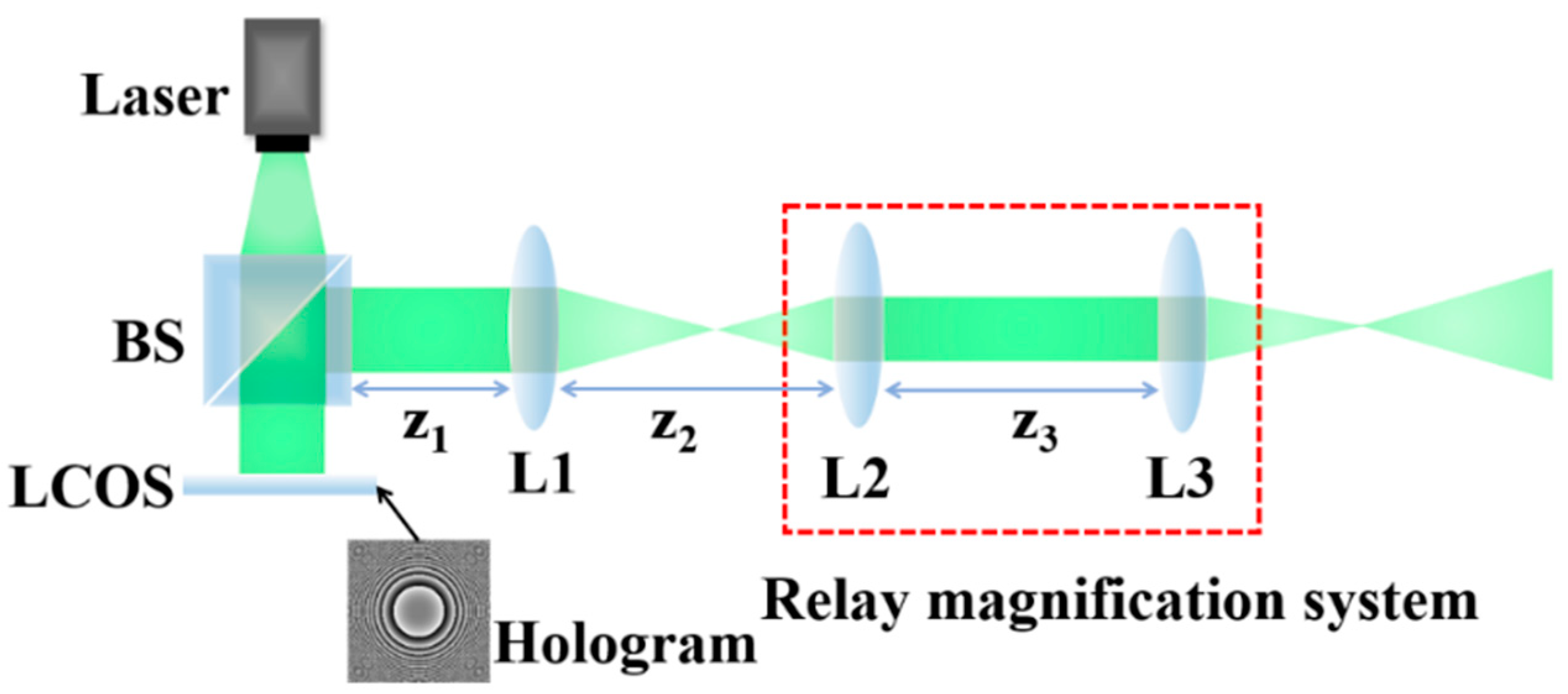
Figure 1 shows the design of our proposed optical launching unit with the beam shaping capability. A pigtailed single-mode laser diode (Thorlabs LP450-SF15, Newton, NJ, USA) operating at 450 nm was used as the light source. Then a fibre-coupled collimator (Thorlabs F671FC-405, Newton, NJ, USA) was used to slow the divergence of the laser beam. The wavefront of the collimated beam was spatially modulated by a phase-only liquid crystal on silicon (LCOS) device (CamOptics COVIS-2K, Cambridge, UK). This LCOS device has a bit depth of 8 bit, i.e., 256 unique phase levels between 0 and 2.5π. The phase flicker of the LCOS was optimised [22,23]. The reflectance of the LCOS device was ~80%; however, it can be improved by applying a dielectric mirror coating on the LCOS backplane [24]. The desired beam can be generated with the Fourier transform lens (L1, f1 = 500 mm) in the system. A 4f magnification system based on L2 (f2 = 250 mm) and L3 (f3 = 500 mm) were used to further enlarge the shaped beam. For the proof-of-concept demonstration, a beam splitter (BS) was used in the current system; this can be replaced with a prism to further increase the energy efficiency of this optical launching unit [25].
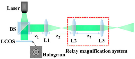
Figure 1.
Setup of the optical launching unit.
Two types of beam shaping techniques were investigated in this work. The first one uses holograms that exhibit radially symmetric cubic phase profiles, which is described by the following equation [26,27]:
where r is the radial distance and b is a coefficient optimised for different charging distances.
The second type utilises holograms that follow the Fresnel lens shape [28,29], which is described by:
where r is the radial distance and b is related to focal length of the Fresnel lens. Again, the value of b can be optimised for different charging distances.
Figure 2 shows the general architecture of our testbed. A pigtailed single-mode laser diode (Thorlabs LP450-SF15, Newton, NJ, USA) operating at 450 nm was driven by Thorlabs LDM9LP to provide a constant DC of 35 mA with an output power of approximately 4.37 mW. This driver unit also integrated a thermoelectric cooler module to maintain the laser performance during the experiment. Then the laser was fed from the single-mode fibre into an optical launching unit for collimation and beam shaping before entering the channel. At the receiver side, a low-cost PV cell was used to collect the incident optical power. In this way, the received optical power was converted into electric power to charge a target device. A source meter (KEITHLEY-2400, Portland, OR, United States) was used to collect the voltage and current passing through the cell. In this work, we tested wireless optical charging in both free spaces and water environments.
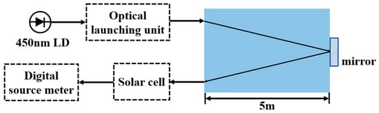
Figure 2.
General architecture of the testbed.
3. Results
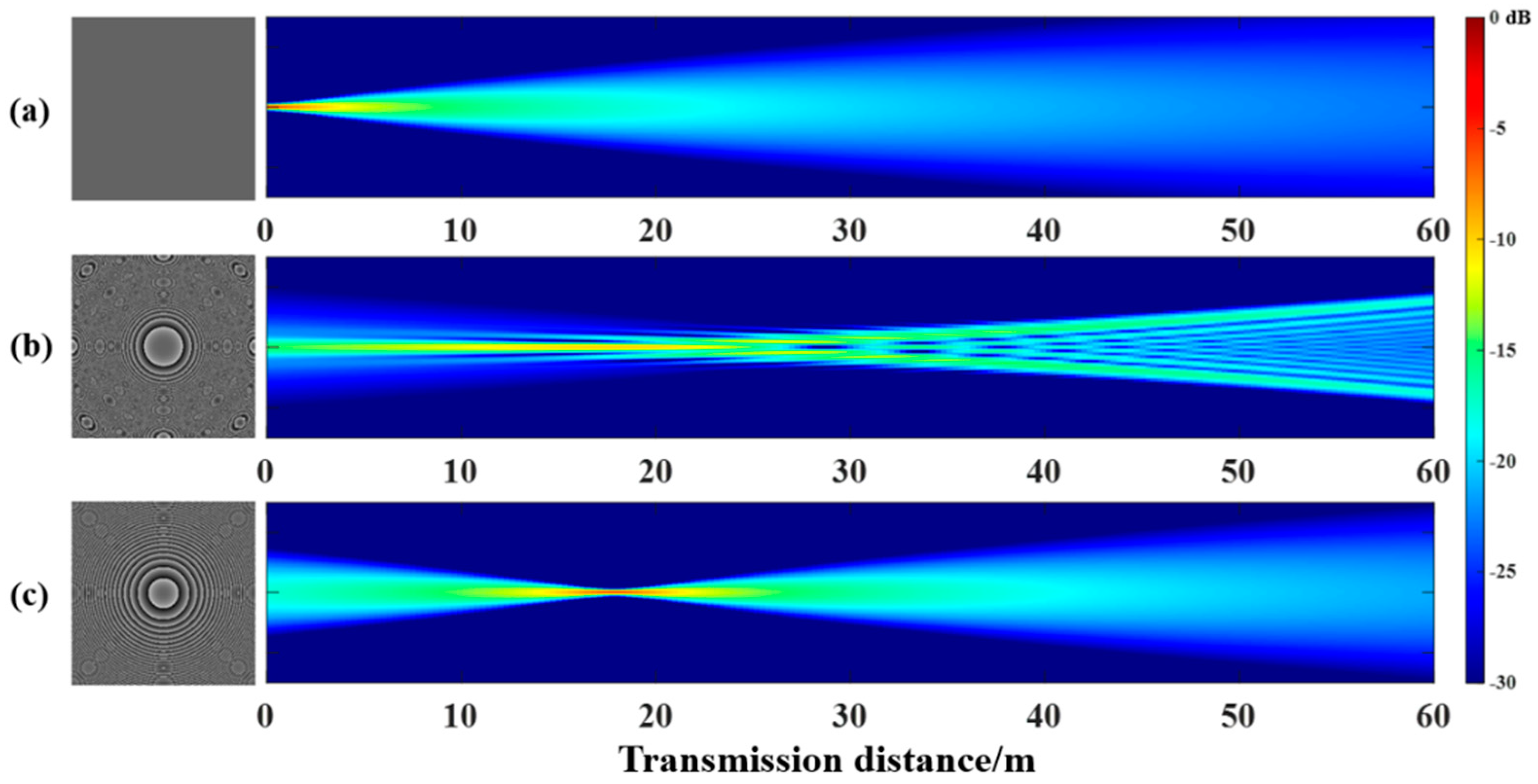
First, simulations based on the Fourier optics theory [30] were conducted to investigate the performance of the optical launching unit. It should be noted that a 4f system of L2 and L3 had a magnification factor of 2. The transmission medium was assumed to be homogeneous and had a refractive index of 1. The results were shown in Figure 3. Figure 3a corresponded to the beam propagation behaviour when the optical beam shaping was not applied. It diverged with a fixed angle while propagating through the medium. Figure 3b corresponded to the case when a radially symmetric cubic phase modulation applied with b = . The beam showed a strong self-focusing characteristic within the first ~20 m before diverging. The highest intensity of the modulated beam was 7.8 dB higher than the Gaussian beam at the same distance. This simulation results when the Fresnel lens phase hologram with a value of was illustrated in Figure 3c. In this case, the position of the maximum light intensity was similar to Figure 3b. A further improvement of 4.01 dB was achieved. After passing through the focal point, the light field diverged as a Gaussian beam. The simulation results showed that the Fresnel phase hologram was more effective than the radially symmetric cubic phase hologram.
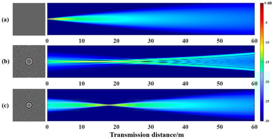
Figure 3.
The phase holograms and simulated characteristics of the launched beams (a) without beam shaping; (b) with the cubic modulation beam shaping when ; (c) with the Fresnel modulation beam shaping when .
Subsequently, the impact of b values on the system of beam propagation characteristics was analysed. As shown in Figure 4, the focusing position of the beam increased with the value of b when the cubic modulation was implemented. Although the peak light intensity decreased for the longer transmission distances, it was always significantly higher than the standard Gaussian beam without beam shaping.
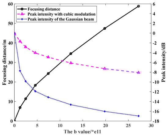
Figure 4.
The trend of focusing distance and intensity with b value when loading the cubic modulation hologram.
Figure 5 showed corresponding results when the Fresnel modulation was used. The trend was similar to that observed in Figure 4. The notable difference was that the intensity attenuation was very small at different focusing distances with Fresnel modulation. Compared with cubic modulation, Fresnel modulation can increase the light intensity more significantly.
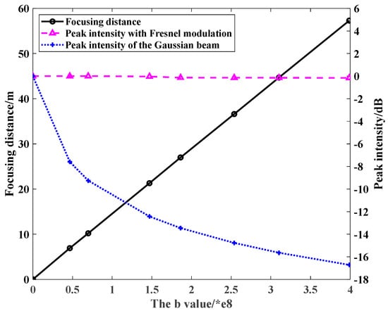
Figure 5.
The trend of focusing distance and intensity with b value when loading the Fresnel modulation hologram.
In our experiment, the voltage-current curve of the PV cell was measured by a source metre. The measurement was conducted when the PV cell was placed 10 m away from our launching unit and the beam shaping was not applied. The results were plotted in Figure 6. The maximum power generated in this specific setting was 1.91 µW with a load resistance of 5250 Ω.
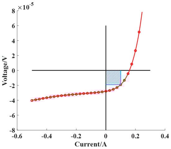
Figure 6.
Voltage vs. current curve of the PV cell.
Subsequently, we measured the maximum electrical power generated by the PV cell under different beam shaping configurations. The experiment was first conducted in the free space between 4 m and 10 m. The value of b was optimised for each transmission distance. Figure 7 illustrated the maximum power generated at each plane. It can be seen that the generated power decreased over the distance. However, the drop was most significant when no beam shaping was applied. When the Fresnel phase modulation was used, the decrease in power was the slowest. The value of b used in each measurement was listed in Table 1.
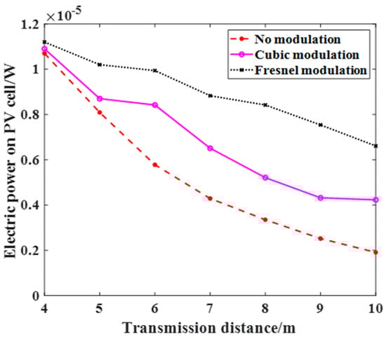
Figure 7.
The maximum electrical power obtained by source metre conversion at different planes.

Table 1.
The values of b used in the experiments.
Figure 8 showed the relative improvement in the charging efficiency at each plane when compared with the results measured without beam shaping. At 10 m, the charging efficiency increased by 246% when the Fresnel modulation was used.
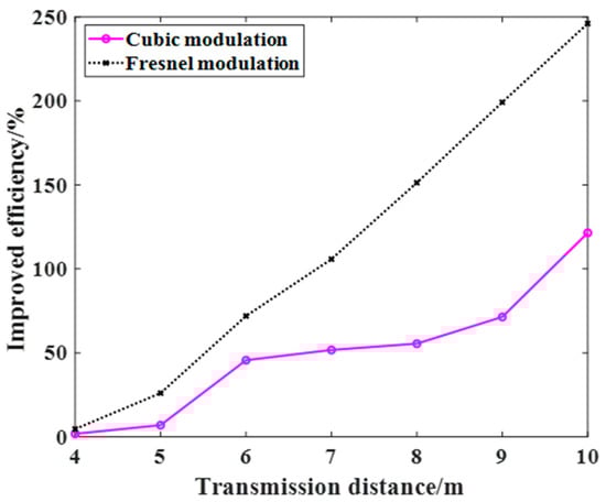
Figure 8.
The efficiency of power improvement.
We then conducted the same experiment in a water tank. The attenuation coefficient of water in the tank was measured as ~0.25/m, which was similar to the Jerlov II water conditions. The experimental results underwater were nearly the same as those in free space. Since the tank was 5 m long, only the situations at 5 m and 10 m were tested. At 5 m, the radially symmetric cubic phase modulation increased power by 21.33% over the Gaussian and the Fresnel phase modulation by 26.22%. At 10 m, the former increased by 176.24% and the latter by 354.88%. At a longer distance, the beam size without shaping became significantly larger. The beam shaping techniques were able to concentrate the optical power at an arbitrary receiver plane. Therefore, its effect became more apparent at a longer distance, improving the overall system efficiency.
4. Conclusions
In this work, we demonstrated two holographic optical beam shaping techniques that could improve the optical energy transfer efficiency in free spaces and underwater environments. In a proof-of-concept experiment, both techniques demonstrated focusing capability at different distances. The beam shaping based on the Fresnel lens modulation performed better than the radially symmetric cubic phase modulation. We believe the holographic optical beam shaping technique has the potential for application in underwater wireless optical charging systems, where the accessibility is poor, and the RF transmission is inefficient. Although the power currently generated in this work is low, it could be significantly improved by using more powerful laser sources and more efficient PV cells. Using the beam splitter in our current configuration also limited the overall efficiency of the system. However, it can be easily solved by replacing the beam splitter with a prism, as previously mentioned. Alternatively, transmissive phase-only spatial light modulators can also be used.
Author Contributions
Conceptualization, H.Y.; methodology, H.Y.; validation, L.T. and J.N.; formal analysis, L.T., J.N. and H.Y.; writing—original draft preparation, L.T.; writing—review and editing, L.T., J.N. and H.Y.; supervision, H.Y.; funding acquisition, H.Y. All authors have read and agreed to the published version of the manuscript.
Funding
This research and APC were funded by the Natural Science Foundation of Jiangsu Province (BK20200351); Jiangsu Special Professorship.
Acknowledgments
The authors would like to thank Chaogang Lou for providing the source metre.
Conflicts of Interest
The authors declare no conflict of interest.
References
- Garnica, J.; Chinga, R.A.; Lin, J. Wireless Power Transmission: From Far Field to Near Field. Proc. IEEE 2013, 101, 1321–1331. [Google Scholar] [CrossRef]
- Fisher, T.M.; Farley, K.B.; Gao, Y.; Bai, H.; Tse, Z.T.H. Electric vehicle wireless charging technology: A state-of-the-art review of magnetic coupling systems. Wirel. Power Transf. 2014, 1, 87–96. [Google Scholar] [CrossRef]
- Lu, X.; Wang, P.; Niyato, D.; Kim, D.I.; Han, Z. Wireless Charging Technologies: Fundamentals, Standards, and Network Applications. IEEE Commun. Surv. Tutor. 2016, 18, 1413–1452. [Google Scholar] [CrossRef] [Green Version]
- Zhou, J.; Zhang, B.; Xiao, W.; Qiu, D.; Chen, Y. Nonlinear Parity-Time-Symmetric Model for Constant Efficiency Wireless Power Transfer: Application to a Drone-in-Flight Wireless Charging Platform. IEEE Trans. Ind. Electron. 2019, 66, 4097–4107. [Google Scholar] [CrossRef]
- Dai, J.; Ludois, D.C. Single active switch power electronics for kilowatt scale capacitive power transfer. IEEE J. Emerg. Sel. Top. Power Electron. 2014, 3, 315–323. [Google Scholar]
- Sakai, N.; Itokazu, D.; Suzuki, Y.; Sakihara, S.; Ohira, T. One-kilowatt capacitive Power Transfer via wheels of a compact Electric Vehicle. In Proceedings of the 2016 IEEE Wireless Power Transfer Conference (WPTC), Aveiro, Portugal, 5–6 May 2016; pp. 1–3. [Google Scholar]
- Jawad, A.M.; Nordin, R.; Gharghan, S.K.; Jawad, H.M.; Ismail, M. Opportunities and Challenges for Near-Field Wireless Power Transfer: A Review. Energies 2017, 10, 1022. [Google Scholar] [CrossRef]
- Abou Houran, M.; Yang, X.; Chen, W. Magnetically Coupled Resonance WPT: Review of Compensation Topologies, Resonator Structures with Misalignment, and EMI Diagnostics. Electronics 2018, 7, 296. [Google Scholar] [CrossRef] [Green Version]
- Sasaki, S.; Tanaka, K.; Maki, K. Microwave Power Transmission Technologies for Solar Power Satellites. Proc. IEEE 2013, 101, 1438–1447. [Google Scholar] [CrossRef]
- Shimamura, K.; Sawahara, H.; Oda, A.; Minakawa, S.; Mizojiri, S.; Suganuma, S.; Mori, K.; Komurasaki, K. Feasibility study of microwave wireless powered flight for micro air vehicles. Wirel. Power Transf. 2017, 4, 146–159. [Google Scholar] [CrossRef]
- Jin, K.; Zhou, W. Wireless Laser Power Transmission: A Review of Recent Progress. IEEE Trans. Power Electron. 2019, 34, 3842–3859. [Google Scholar] [CrossRef]
- Khalighi, M.; Gabriel, C.; Hamza, T.; Bourennane, S.; Léon, P.; Rigaud, V. Underwater wireless optical communication; recent advances and remaining challenges. In Proceedings of the 2014 16th International Conference on Transparent Optical Networks (ICTON), Graz, Austria, 6–10 July 2014; pp. 1–4. [Google Scholar]
- Kim, S.-M.; Kwon, D. Transfer Efficiency of Underwater Optical Wireless Power Transmission Depending on the Operating Wavelength. Curr. Opt. Photonics 2020, 4, 571–575. [Google Scholar]
- Duncan, K.J. Laser based power transmission: Component selection and laser hazard analysis. In Proceedings of the 2016 IEEE PELS Workshop on Emerging Technologies: Wireless Power Transfer (WoW), Knoxville, TN, USA, 4–6 October 2016; pp. 100–103. [Google Scholar]
- Zhou, Y.; Miyamoto, T. 200 mW-class LED-based optical wireless power transmission for compact IoT. Jpn. J. Appl. Phys. 2019, 58, SJJC04. [Google Scholar] [CrossRef]
- Uchiyama, N.; Yamada, H. Proposal and demonstration of LED optical wireless power-transmission systems for battery-operated small electronic devices. Jpn. J. Appl. Phys. 2020, 59, 124501. [Google Scholar] [CrossRef]
- Hirota, M.; Iio, S.; Ohta, Y.; Niwa, Y.; Miyamoto, T. Wireless power transmission between a NIR VCSEL array and silicon solar cells. In Proceedings of the 2015 20th Microoptics Conference (MOC), Fukuoka, Japan, 25–28 October 2015; pp. 1–2. [Google Scholar]
- Kim, S.-M.; Choi, J.; Jung, H. Experimental demonstration of underwater optical wireless power transfer using a laser diode. Chin. Opt. Lett. 2018, 16, 80101. [Google Scholar] [CrossRef]
- Höhn, O.; Walker, A.W.; Bett, A.W.; Helmers, H. Optimal laser wavelength for efficient laser power converter operation over temperature. Appl. Phys. Lett. 2016, 108, 241104. [Google Scholar] [CrossRef]
- Valdivia, C.E.; Wilkins, M.M.; Bouzazi, B.; Jaouad, A.; Aimez, V.; Arès, R.; Masson, D.P.; Fafard, S.; Hinzer, K. Five-volt vertically-stacked, single-cell GaAs photonic power converter. In Proceedings of the SPIE, San Francisco, CA, USA, 7–12 February 2015; Volume 9358. [Google Scholar]
- Raible, D.E. High Intensity Laser Power Beaming for Wireless Power Transmission; Cleveland State University: Cleveland, OH, USA, 2008. [Google Scholar]
- Yang, H.; Chu, D.P. Phase flicker optimisation in digital liquid crystal on silicon devices. Opt. Express 2019, 27, 24556–24567. [Google Scholar] [CrossRef] [PubMed]
- Yang, H.; Chu, D.P. Phase flicker in liquid crystal on silicon devices. J. Phys. Photonics 2020, 2, 032001. [Google Scholar] [CrossRef]
- Yang, H.; Chu, D.P. Digital phase-only liquid crystal on a silicon device with enhanced optical efficiency. OSA Contin. 2019, 2, 2445–2459. [Google Scholar] [CrossRef]
- Liu, S.; Qi, S.; Zhang, Y.; Li, P.; Wu, D.; Han, L.; Zhao, J. Highly efficient generation of arbitrary vector beams with tunable polarization, phase, and amplitude. Photonics Res. 2018, 6, 228–233. [Google Scholar] [CrossRef]
- Zhang, Z.; Liang, X.; Goutsoulas, M.; Li, D.; Yang, X.; Yin, S.; Xu, J.; Christodoulides, D.N.; Efremidis, N.K.; Chen, Z. Robust propagation of pin-like optical beam through atmospheric turbulence. APL Photonics 2019, 4, 76103. [Google Scholar] [CrossRef] [Green Version]
- Nie, J.; Tian, L.; Yue, S.; Zhang, Z.; Yang, H. Advanced Beam Shaping for Enhanced Underwater Wireless Optical Communication. In Proceedings of the 2021 Optical Fiber Communications Conference and Exhibition (OFC), San Francisco, CA, USA, 6–10 June 2021. [Google Scholar]
- Nie, J.; Tian, L.; Wang, H.; Chen, L.; Li, Z.; Yue, S.; Zhang, Z.; Yang, H. Adaptive beam shaping for enhanced underwater wireless optical communication. Opt. Express 2021, 29, 26404–26417. [Google Scholar] [CrossRef]
- Robertson, B.; Zhang, Z.; Yang, H.; Redmond, M.M.; Collings, N.; Liu, J.; Lin, R.; Jeziorska-Chapman, A.M.; Moore, J.R.; Crossland, W.A.; et al. Application of the Fractional Fourier Transform to the Design of LCOS Based Optical Interconnects and Fiber Switches. Appl. Opt. 2012, 51, 2212–2222. [Google Scholar] [CrossRef]
- Goodman, J.W. Introduction to Fourier Optics, 2nd ed.; McGraw-Hill Series in Electrical and Computer Engineering; McGraw-Hill: New York, NY, USA, 1996; ISBN 0070242542. [Google Scholar]


Publisher’s Note: MDPI stays neutral with regard to jurisdictional claims in published maps and institutional affiliations. |
© 2021 by the authors. Licensee MDPI, Basel, Switzerland. This article is an open access article distributed under the terms and conditions of the Creative Commons Attribution (CC BY) license (https://creativecommons.org/licenses/by/4.0/).