Abstract
Double recalescence in many ferrous alloy systems involves rapid solidification of metastable ferrite from the undercooled melt with subsequent transformation to stable austenite. Containerless processing is used to monitor the process using pyrometry and high-speed cinematography such that delay behavior can be predicted based on the application of the retained damage model (RDM). When comparing Fe-Cr-Ni alloys to Fe-Co alloys, the cluster attachment rate is enhanced while free energy retention is reduced. These trends are tied to specific alloy properties. A retained free energy criterion is proposed based on the ratio of thermophysical properties used to define the transformation driving force such that the thermodynamic limit for energy retention may be predicted. Surprisingly, at long delay times, healing occurs such that much of the retained free energy is not available to enhance the transition from metastable to stable phases. At delay times less than one second, no healing is observed and the RDM correctly predicts transformation delay behavior over a wide range of alloy compositions.
1. Introduction
In order to control the phase selection and subsequent microstructural evolution in solidification processes involving rapid heat extraction, such as additive manufacturing, spray forming, and welding, the thermodynamic limits that define transformation kinetics must be understood. The retained damage model (RDM) is used to predict the delay, or incubation time, between primary and secondary recalescence events during rapid solidification, where transformation from molten metallic alloy liquid passes through a metastable intermediary primary phase before conversion to a stable secondary phase. The RDM was developed to explain the influence of undercooling and stirring on the conversion of metastable bcc ferrite to stable fcc austenite in ternary Fe-Cr-Ni alloys [,,,,,,,]. Previous work showed that the influence of undercooling alone may be evaluated by investigation of transformation behavior during processing using electrostatic levitation (ESL), where convection during undercooling is negligible. This contrasts the behavior during electromagnetic levitation (EML) processing where convection and undercooling simultaneously impact the delay. By applying the results from ESL to the EML results, it is possible to isolate the impact on transformation delay due to convection alone. No previous modeling effort has successfully been employed to numerically distinguish between these effects.
The model is based on an analogy of hot working of a material whereby defect energy is introduced into a microstructure to drive subsequent recrystallization to the parent phase (known as healing) or promote transformation to a new phase. In the case of the Fe-Cr-Ni alloy family, the introduction of this damage free energy results in significant reduction in the delay time observed between the primary and secondary nucleation events in a process known as double recalescence.
The model relies on an evaluation of the global thermodynamic limit to how much free energy can be retained to subsequently drive the second transformation []. In addition to the classical free energy contribution resulting from undercooling relative to the stable phase ΔGs [], when defining the total free energy that drives the transformation ΔGT, as seen in Equation (1), a second and third term are added to track the contribution from metastable undercooling ΔGm and melt shear ΔGc; in the absence of convection, this third term goes to zero. These terms may be reduced by healing, and this effect is tracked using an experimentally derived retained energy parameter fx representing the fraction of available free energy from primary undercooling, which is retained:
The relationship between delay time and free energy is based on the principle of microscopic reversibility [] such that, in a manner functionally constant with Kantrowicz [] and Kaschiev [], the delay is inversely proportional to the attachment rate β and the free energy raised to the fourth power, m = 4 [], as shown in Equation (2). β represents a measure of the success rate for an atom attaching to the cluster as it grows to critical size. Note that the negative sign in the original derivation is required since the curvature at critical size is negative.
A dimensionless approach is then used to evaluate model performance using a reference state representing the longest delay time possible, which occurs at the minimum free energy condition, as seen in Equation (3). This reference state is defined from the equilibrium phase diagram, where ΔTm = 0, ΔGm = 0, and ΔGR = ΔGs. The dimensionless driving force NM is based on the ratio of the total free energy at the conditions where the experiment was run, including any retained energy, to the free energy at the reference state. Thus, NM is only a function of the experimentally observed undercooling ΔTm from Equation (1). The dimensionless delay time ND is based on the ratio of the corresponding experimentally observed delay time to the delay at the reference state, as calculated using Equation (2). Since the undercooling (measured using pyrometry) and delay time (measured using high-speed cinematography) are independently evaluated during any given experiment, these two dimensionless quantities are independent of each other.
The treatment shown in Equation (1) defines a third dimensionless quantity NΞ, shown in Equation (4), representing the ratio of thermophysical properties for metastable and stable phases such that the thermodynamic limit representing the maximum value of fx is defined. Refer to Appendix A for derivation and application of these relationships.
It is expected that the attachment frequency β is higher for Fe-Co than for Fe-Cr-Ni [] for two reasons: First, the liquidus temperatures for Fe-Co alloys are substantially higher than for steel and attachment is assumed to be a thermally-activated process. Second, since the partitioning coefficient shown in Figure 1a is closer to one for Fe-Co, the cluster and parent phase compositions are similar, thus reducing the solute compositional barrier for a stable-phase cluster formation. Conversely, the fraction of damage energy retained fx should be lower because NΞ is lower, as seen in Figure 1b. This is because NΞ and fx are each proportional to the ratio of the free energy required from the metastable phase to that available to the stable phase; refer to Appendix A for the derivation of the criterion limiting fx ≤ NΞ. For Fe-Cr-Ni, fx → 1 as NΞ → 1 and we expect that for Fe-Co, since NΞ < 1 and fx < 1. The purpose of this paper is to investigate these hypotheses in an effort to apply the retained damage model to a new alloy system [,,,].
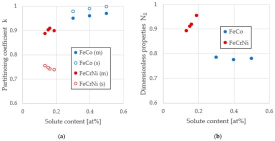
Figure 1.
Characterizing key physical properties from Fe-Co and Fe-Cr-Ni alloy systems. (a) Dimensionless partitioning coefficient k = CS/CL for metastable (m) and stable (s) solid phases; for FeCrNi, the metastable bcc phase rejects Ni and the stable fcc phase rejects Cr; for FeCo, both metastable and stable phases reject the solute Co; (b) dimensionless property parameter NΞ.
2. Materials and Methods
2.1. Containerless Processing Using Electrostatic Levitation
Fe–Co samples were prepared at three compositions of 30, 40, and 50 at % cobalt from pure elemental stock with 99.995% pure Fe and 99.95% pure Co. The components were arc-melted under an argon atmosphere such that the spherical samples had a mass of approximately 40–60 mg (~2 mm diameter). Negatively charged samples were inserted into the NASA Marshall Space Flight Center ESL and levitation was achieved by applying a negative charge to the lower electrode and a positive charge to the upper electrode within a vacuum chamber evacuated to an atmosphere of 10−9 mbar. The location of the sample was determined by positioning lasers such that the lateral and vertical position could be adjusted by PID control. The sample was melted using a 200 watt continuous wave Nd:YAG laser, and then the molten spherical droplet was allowed to radiatively cool until solidified []. Containerless processing of these alloys ensures that contamination of the melt by crucible walls is minimized to encourage attainment of deep undercooling. Since we evaluated data obtain from experiments run using NASA ESL, induced convection was minimized, and any stirring produced by Marangoni convection, resulting from thermal gradients imposed during melting, was dampened out to produce a quiescent melt [,].
2.2. Process Monitoring
During the entire heating cycle, the thermal profile was monitored with a Mikron Infrared Inc. Mi-GA140 single color pyrometer, operating at 16 Hz, with a wavelength range from 1.45 to 1.8 μm, and calibrated using a Mikron M390 blackbody generator, (Integrated Component Sales, Winter Park, FL, USA) []. Directly before primary recalescence and continuing throughout the solidification process, nucleation and growth were monitored with a high-speed digital camera with frame capture rates of up to 50,000 frames per second. The camera was selected based on the temporal and spatial resolution desired for a particular test series and depended on the sample radiance for a given alloy and undercooling range. There were three cameras that were used during testing: Vision Research Phantom V7.1 (Vision Research, Wayne NJ, USA), Integrated Design Tools - IDT MotionPro Y4, and IDTMotionPro Y7 (DEL Imaging Systems LLC, Cheshire CT, USA) []. Image contrast during recalescence is developed based on the differences in radiative intensity associated with the temperature of each phase present; undercooled liquid is dark, the metastable mushy zone is brighter, and the stable phase is brightest. During recalescence, it is possible to track the motion of the growth interface across the sample and thus define the time and location of any nucleation event.
Representative examples of these two methods to evaluate the delay are shown in Figure 2, where four key events are annotated as (1) undercooled liquid, (2) nucleation and growth of the primary metastable phase, (3) mushy zone isothermal hold at the metastable liquidus, and (4) nucleation and growth of the stable phase with recalescence to the stable phase liquidus. The bright spots on the sample are introduced by reflection from the ESL positioning laser system.
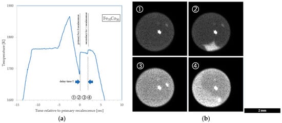
Figure 2.
Double recalescence. (a) Thermal profile from Fe70Co30 pyrometry with annotation of timing of key events; (b) mosaic of Fe60Co40 images showing ① undercooled liquid, ② growth of metastable primary phase, ③ isothermal metastable phase mushy zone delay, and ④ growth of secondary stable phase.
2.3. Analysis Methods
The analytical approach used involved selecting a cluster geometry and attachment mechanism, as previously described in earlier RDM publications [,]. As the total metastable phase undercooling approaches zero, the value of ΔGT approaches the reference condition ΔGR and the delay τ is supposed to approach τR. Under these conditions NM and ND approach 1 and the experimentally derived values at the correct value of β will converge to intersect the axes of a log-log plot at the origin. This defines the attachment rate.
Once the attachment rate is known, experimental values of τ are used to estimate the quantity of retained free energy that is required to obtain the observed delay using Equation (2). This value is compared to an estimate of the retained free energy ΔGM available as calculated from the observed undercooling using Equation (1). A plot of these two quantities yields the slope fx, which must be less than NΞ, based on the retained free energy criterion developed in Appendix A.
3. Results
A plot of the experimentally observed delay times is shown as a function of the undercooling relative to the stable phase in Figure 3. The three alloys studied are differentiated by symbol color. For example, the Fe60Co40 (at %) alloy is named 60-40 and displayed in yellow. Note that the low undercooling (long delay time, red points) behavior for the 70-30 alloy differs significantly from that at high undercooling (short delay time, green points). Since the RDM predictions indicate that the delay time is inversely proportional to the attachment rate, if we increase β, all the solid lines representing model predictions will move down. All lines move together since we assume a common value of β for the entire alloy family; thus, it is easy to identify the appropriate attachment rate from experimental data by minimizing the variance between observed and predicted values for each test. The best fit is obtained for a value of β = 2 × 10⁸ atoms/s.
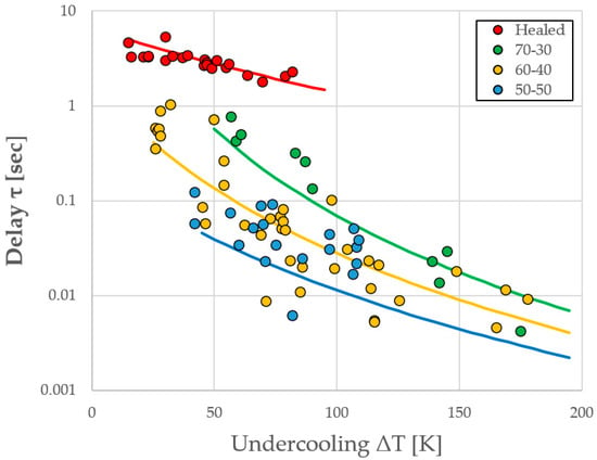
Figure 3.
Experimentally observed delay time as a function of undercooling (ΔT = ΔTs + ΔTm) for the three alloys studied with RDM predictions of behavior, assuming an attachment rate of β = 2 × 10⁸ atoms/s.
A comparison of the Required ΔGm from the measured delay times with the Available ΔGm from the measured undercooling results in a slope of fx = 0.410 ± 0.022 for tests with delay times shorter than one second, shown in Figure 4a, and fxheal = 0.0753 ± 0.0052 for long delay times (only the 70-30 alloy showed healing), displayed in Figure 4b. In subsequent calculations, values of 0.40 and 0.075 are used.
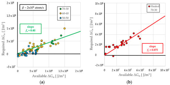
Figure 4.
Evaluation of the retained energy parameter from a plot of required to available retained free energy. (a) Data for all alloys at delays τ < 1 s; (b) data for healed Fe70Co30 at delays τ > 1 s.
4. Discussion
The discussion section is provided in four parts to highlight the influence of key experimentally determined parameters on the performance of the RDM. A summary of the key parameters used in the calculations to define the RDM predictions is provided in Table 1. If two values are presented, the first is for the metastable bcc ferrite, while the second is for the stable fcc austenite phase. Where appropriate, literature references are indicated in the units column of Table 1.

Table 1.
Retained damage model parameters.
4.1. Attachment Rate β
The attachment rate is a measure of the success rate of the incremental growth of the subcritical cluster, and we expected that several material properties would influence the value of this quantity. Since attachment is probably a thermally activated process akin to diffusion, the metastable liquidus temperature is an important parameter because this represents the isothermal hold temperature that characterizes conditions during which the stable cluster develops. The alloys studied have a liquidus in the range of 1669 < TLmFeCrNi < 1716 K [,] for the steels and 1714 < TLmFeCo < 1753 K [,] for Fe-Co; thus, we expected attachment to be greater for Fe-Co based on an anticipated increase in attachment attempt frequency. Additionally, differences in solute concentration between the parent phase and the developing critical nucleus tend to present a barrier to cluster growth. As the partitioning coefficient approaches one, the attachment/detachment process will become more reversible. Partitioning for the stable phase is more significant for steels with ~0.75 than for Fe-Co with ~0.98, indicated in Figure 1a. Again, we expected the attachment rate to be greater for Fe-Co based on an anticipated increase in the rate of attachment success (alternately known as the “accommodation coefficient for growth” []). Contrasting attachment rates, the stainless steel value of βFeCrNi = 4 × 10⁷ atoms/s [] compares well to the Fe-Co alloy family value, which is on the order of 5× higher at βFeCo = 2 × 10⁸ atoms/s. Future work will involve investigating if attachment can be linked directly to an Arrhenius-type relationship within an alloy family instead of assuming it is constant for the entire family.
4.2. Retained Energy Parameter fx
The retained energy parameter is a measure of the fraction of available free energy from primary undercooling, which is used to promote stable phase nucleation and thus reduce the transformation delay. Key thermophysical properties are combined to develop the properties dimensionless quantity NΞ, as shown in Figure 1b. For steels, the parameter NΞ → 1 implies that all retained free energy is available to drive the transformation; free energy is apparently conserved. This is a seductive argument, but for Fe-Co, the situation is different because NΞ is significantly reduced; based on the retained free energy criterion in Appendix A, the thermodynamic limit requires that fx is significantly depressed. Since fx ≪ NΞ, the ratio decreases by almost a factor of two, since 0.41 ≪ 0.79. Only half of the free energy available is used. Further work is required to understand the processes behind this observation, but this theory establishes limits that are consistent with behavior across several alloy families.
4.3. Healing at Long Delay Times
An additional attribute of the RDM is the ability to investigate recrystallization of the parent phase during the isothermal hold, which characterizes the delay period; this represents healing of the retained damage. If healing occurs in a particular undercooling range, particularly at long times associated with low undercooling, then it would be expected that the slope would decrease such that it deviates from NΞ dramatically. This was observed for the 70-30 alloy, as shown when comparing the behavior at high undercoolings in Figure 4a (green symbols) with low undercoolings in Figure 4b (red symbols). Special treatment is required to evaluate samples where healing occurs. As seen in Figure 2a, after a brief isothermal hold at the metastable liquidus TLm, the temperature begins to drop as heat extraction to the environment allows the system to equilibrate to the metastable solidus TSm. The thermal driving force ΔTs is thus increased such that the solidus temperature replaces the liquidus temperature wherever it appears in Equation (1). This also increases ΔGs and ΔGT in Equation (1) and NΞ in Equation (4). With a decrease in T and an increase in (ΔGT)m in Equation (2), τR becomes reduced while ΔGR becomes increased; both these significant changes have a substantial effect on the fit in Figure 4b that identifies the slope that defines the healed retained energy parameter fxheal ≪ fx.
4.4. Dimensionless Presentation of RDM Predictions
With RDM fit parameters β = 2 × 10⁸ atoms/s, fx = 0.40, and fxheal = 0.075, Equation (1) was used to evaluate ΔGT and thus to predict values for τ using Equation (2). The results are displayed in Figure 3. The two independent dimensionless parameters may now be calculated using Equation (3). The relationship between these independent variables is plotted in Figure 5, which shows a slope of negative m = 3.938 ± 0.123, which agrees well with the theoretical value for a slope of negative m = 4 from τ = C/β(ΔG)m, given that the value of C varies by alloy as shown in Equation (2) and Table 1. Note that for the healed data, there is also agreement is with m = 4.042 ± 0.273 based on the proposed modification of the thermal driving force and fx.
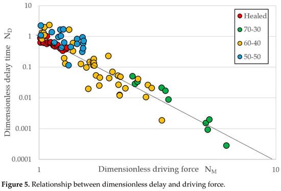
Figure 5.
Relationship between dimensionless delay and driving force.
5. Conclusions
The retained damage model, developed for Fe-Cr-Ni rapid solidification, was successfully applied to the Fe-Co alloy family. The results confirmed the hypothesis that the attachment frequency β is significantly higher in Fe-Co than observed in Fe-Cr-Ni. Additionally, as predicted, the fraction of available energy that is retained fx was found to be significantly lower, although the observed value is a factor of two lower than the theoretical maximum predicted by NΞ, using the retained free energy criterion. A surprising result was the observation of significant healing for delay times longer than one second, a condition only seen for the 70-30 alloy, such that the fraction of available energy at low undercoolings is dramatically reduced; at low undercoolings, fx starts at a value of 0.075, and when high undercoolings and short delay times are reached for τ < 1 s, this value rises to 0.4, as observed for the rest of the Fe-Co alloy family. No healing appears to be possible if the delay is short enough. Now that the influence of undercooling on transformation delay for FeCo has been defined from ESL tests, future evaluations on the influence of convection on delay may begin based on additional EML testing.
Author Contributions
Conceptualization, D.M.M.; methodology, J.E.R.; software, X.L., S.J. and D.M.M.; formal analysis, X.L., S.J. and D.M.M.; investigation, J.E.R. and O.S.; data curation, D.M.M.; writing—review and editing, X.L., D.M.M., J.E.R. and S.J.; supervision, project administration, and funding acquisition, D.M.M. All authors have read and agreed to the published version of the manuscript.
Funding
This research was funded by NASA grants 80NSSC19K0256 and NNX17AH41G in collaboration with ESA using the ISS-EML facility and with JAXA using the ELF facility, respectively. The authors further acknowledge DLR German Space Administration grant 50WM1546 project PARMAG.
Institutional Review Board Statement
Not applicable.
Informed Consent Statement
Not applicable.
Data Availability Statement
The data presented in this study are available on request from the corresponding author.
Conflicts of Interest
The authors declare no conflict of interest.
Appendix A
One key model parameter is the retained energy parameter fx, which represents the ratio of the retained free energy required to drive the transformation to that available from thermal undercooling. Since there cannot be more free energy retained than was available during primary recalescence, a limit exists on the value of this parameter. In order to numerically define the thermodynamic limits on fx, the driving force during double recalescence ΔGT must be evaluated based on the relative undercoolings for each transformation, as shown previously in Equation (1). Additionally, we defined a dimensionless property number NΞ in Equation (4) based on the ratio of thermophysical quantities used to define the free energies for each transformation (note that this definition corrects a typographical error contained in [,]). Expanding Equation (1) based on Equation (4) yields an expression for the driving force as a function of a modified undercooling term ΔTTX, which transforms contributions by metastable phase free energy terms to a stable phase basis:
A criterion can thus be developed based on the overall undercooling relative to the stable phase liquidus (equivalent to recalescence from the undercooled liquid directly to the stable phase liquidus ΔTT):
The overall available thermal driving force is thermodynamically limited by the phase diagram such that the function in parentheses from Equation (A1) cannot be greater than the overall undercooling in Equation (A2) and thus ΔTTX ≤ ΔTT:
The retained free energy criterion can therefore be restated as fx ≤ NΞ in the absence of convection. At the extremes, if fx = NΞ, then the two values in parentheses in Equation (4) are equivalent and all free energy is retained such that the thermal driving force corresponds to ΔTT. At the other extreme, if fx = 0, then there is no contribution by retained energy from primary metastable recalescence and ΔGT = ΔGs. Note that this new insight requires the original definition of the contribution to free energy from melt convection, or more correctly, from melt shear, be slightly altered as presented in Equation (A4) to account for values of NΞ varying from one such that:
The inclusion of the dimensionless property number is required because for steel alloys , and this term is ignored. For Fe-Co, , and it cannot be ignored.
References
- Matson, D.M. Influence of induced convection on transformation kinetics during rapid solidification of steel alloys: The Retained Damage Model. JOM 2020, 72, 4109–4116. [Google Scholar] [CrossRef]
- Matson, D.M. Retained free energy as a driving force for phase transformation during rapid solidification of stainless steel alloys in microgravity. NPJ Microgravity 2018, 4, 1–6. [Google Scholar] [CrossRef] [PubMed] [Green Version]
- Matson, D.M.; Xiao, X.; Rodriguez, J.E.; Lee, J.; Hyers, R.W.; Shuleshova, O.; Kaban, I.; Schneider, S.; Karrasch, C.; Burggraff, S.; et al. Use of Thermophysical Properties to Select and Control Convection during Rapid Solidification of Steel Alloys using Electromagnetic Levitation on the Space Station. JOM 2017, 69, 1311–1318. [Google Scholar] [CrossRef] [Green Version]
- Matson, D.M. Chapter 10—Nucleation within the Mushy Zone. In Solidification of Containerless Undercooled Melts; Herlach, D.M., Matson, D.M., Eds.; Wiley-VCH: Weinheim, Germany, 2012; pp. 213–238. ISBN 9783527331222. [Google Scholar]
- Matson, D.M.; Xiao, X.; Jeon, S. Optimization strategies for identifying the controlling mechanism for solid-state transformation in FeCrNi during rapid solidification. IOP Conf. Ser. Mater. Sci. Eng. 2019, 529, 1–7. [Google Scholar] [CrossRef]
- Turnbull, D. Formation of crystal nuclei in liquid metals. J. Appl. Phys. 1950, 21, 1022–1028. [Google Scholar] [CrossRef]
- Feder, J.; Russell, K.C.; Lothe, J.; Pound, G.M. Homogeneous nucleation and growth of droplets in vapours. Adv. Phys. 1966, 15, 111–178. [Google Scholar] [CrossRef]
- Kantrowitz, A. Nucleation in very rapid vapor expansions. J. Chem. Phys. 1951, 19, 1097–1100. [Google Scholar] [CrossRef]
- Kashchiev, D. Nucleation at existing cluster size distributions. Surf. Sci. 1969, 18, 389–397. [Google Scholar] [CrossRef]
- Liu, X. Effect of Stirring and Undercooling on Nucleation in Fe-Co Alloys. BS Honors Thesis, Mechanical Engineering Department, Tufts University, Medford, MA, USA, May 2021. [Google Scholar]
- Rodriguez, J.E.; Matson, D.M. Thermodynamic Modeling of the Solidification Path of Levitated Fe-Co Alloys. Calphad 2015, 49, 87–100. [Google Scholar] [CrossRef]
- Rodriguez, J.E.; Kreischer, C.; Volkmann, T.; Matson, D.M. Solidification velocity of Undercooled Fe-Co Alloys. Acta Mater. 2017, 122, 431–437. [Google Scholar] [CrossRef] [Green Version]
- Rodriguez, J.E.; Matson, D.M. Lateral Heat Flux during Remelt Growth into the Mushy-zone. Acta Mater. 2017, 129, 408–414. [Google Scholar] [CrossRef]
- Rogers, J.R.; SanSoucie, M.P. Containerless processing studies in the MSFC electrostatic levitator. In Proceedings of the 50th AIAA Aerospace Science Meeting, AIAA 2012-0924, Nashville, TN, USA, 9–12 January 2012; pp. 1–7. [Google Scholar] [CrossRef]
- Matson, D.M.; Fair, D.J.; Hyers, R.W.; Rogers, J.R. Contrasting Electrostatic and Electromagnetic Levitation Experimental Results for Transformation Kinetics of Steel Alloys. Ann. N. Y. Acad. Sci. 2004, 1027, 435–446. [Google Scholar] [CrossRef] [PubMed]
- Matson, D.M.; Hyers, R.W.; Volkmann, T.; Fecht, H.-J. Phase selection in the mushy zone: LODESTARS and ELFSTONE Programs. J. Phys. Conf. Ser. 2011, 327, 1–7. [Google Scholar] [CrossRef] [Green Version]
- Burke, J.M.; Mueller, A.J.; Fair, D.J.; Matson, D.M. Application of EM Levitation Processing: Fundamental Studies of Steel Rapid Solidification. In Materials Science and Technology 2: Electromagnetics in Materials Processing; Hyers, R.W., Matson, D.M., Williams, D.J., Eds.; TMS Press: Warrendale, PA, USA, 2006; pp. 71–78. [Google Scholar]
- Rodriguez, J.E. Thermodynamic and Growth Kinetic Modelling of Solidification from a Metastable Mushy-Zone. Ph.D. Thesis, Mechanical Engineering Department, Tufts University, Medford, MA, USA, August 2016. [Google Scholar]
Publisher’s Note: MDPI stays neutral with regard to jurisdictional claims in published maps and institutional affiliations. |
© 2021 by the authors. Licensee MDPI, Basel, Switzerland. This article is an open access article distributed under the terms and conditions of the Creative Commons Attribution (CC BY) license (https://creativecommons.org/licenses/by/4.0/).