Article

Structure and Mechanical Properties of PVD and CVD TiAlSiN Coatings Deposited on Cemented Carbide

1
State Key Laboratory of Powder Metallurgy, Central South University, Changsha 410083, China
2
Ganzhou Achteck Tool Technology Co., Ltd., Ganzhou 341000, China
3
International Institute for Materials Innovation, Nanchang University, Nanchang 330031, China
4
Faculty of Materials Metallurgy and Chemistry, Jiangxi University of Science and Technology, Ganzhou 341000, China
*
Authors to whom correspondence should be addressed.
Crystals 2021, 11(6), 598; https://doi.org/10.3390/cryst11060598
Submission received: 25 April 2021 / Revised: 20 May 2021 / Accepted: 22 May 2021 / Published: 25 May 2021
(This article belongs to the Special Issue Thin Films and Coatings: Modeling Meets Experiment)

Abstract

:
This work reports the results of our investigation of the structure and mechanical properties of physical vapor deposition (PVD) and chemical vapor deposition (CVD) TiAlSiN coatings deposited on cemented carbide substrates. For the first time, a novel nanocomposite of Ti0.13Al0.85Si0.02N coating deposited from TiCl4-AlCl3-SiCl4-NH3-H2 gas precursors was prepared by low pressure chemical vapor deposition (LPCVD) at 780 °C and a pressure of 60 mbar, while PVD Ti0.31Al0.60Si0.09N coating was prepared using the arc ion plating method. The investigation results including morphology, microstructure, chemical composition, phase component, and hardness were carried out by scanning electron microscopy (SEM) equipped with energy dispersive spectrometer (EDS), transmission electron microscopy (TEM), X-ray diffraction (XRD), and nano-indentator. TEM results revealed that both PVD and CVD TiAlSiN coatings consisted of nanocrystalline embedded in SiNx amorphous. The nanohardness of CVD Ti0.13Al0.85Si0.02N coating obtained in this work was 31.7 ± 1.4 GPa, which was 35% higher than that of the PVD Ti0.31Al0.60Si0.09N coating.

1. Introduction

With the increasing demands for materials used in dry and high speed cutting and machining in the metalworking industry, it is imperative to develop a coated cemented carbide cutting tool with improved performance. As a traditional hard coating, TiN single layer coating has been widely used due to the similar thermal expansion coefficient with high speed steel tools. However, it has been reported that TiN coatings become oxidized at the temperature of 500–600 °C which limits its application in high temperature working environment [1]. Subsequently, TiAlN coating, which was evolved from the Ti-N single layer coating, has developed dramatically in recent decades due to their superior stability, even at elevated temperatures of approximately 800 °C and advanced mechanical properties [2,3,4,5]. In general, the increase of Al content in fcc-Ti1-xAlxN coating can improve the oxidation resistance of the coating. A large number of studies have revealed that the maximum Al content of fcc-Ti1-xAlxN coating prepared by PVD technology is 0.6~0.7, while Endler et al. [6] prepared fcc-Ti1-xAlxN coating with Al content of 0.9 by means of CVD method. Meanwhile, much attention was also recently paid to the development of TiSiN coating, which consists of nano-crystalline TiN and amorphous SiNx with high physical and mechanical properties, such as superhardness (>40 GPa), high oxidation resistance (around 850 °C), and high thermal stability (up to 1100 °C) [7,8,9,10]. Qiu et al. [11] reported that the TiSiN coating prepared at 850 °C and 3.0 kPa was composed of amorphous Si3N4 coated nanocrystalline TiN, with small grain size (17.7 nm) and high hardness of 30.4 ± 0.5 GPa. More recently, the quaternary Ti–Al–Si–N system started to be explored, since it can have the merits of both TiAlN and TiSiN coatings. Due to its high hardness, thermal stability, and oxidation resistance, TiAlSiN superhard coatings are eagerly expected to be applied widely in high speed processing conditions to improve industrial efficiency.
A number of groups have deposited TiAlSiN coatings by various PVD methods, such as magnetron sputtering [12,13,14,15,16,17], arc ion plating [18,19,20,21,22], cathodic arc evaporation [23,24,25,26,27,28], and the arc ion plating combined with a magnetron sputtering technique [29,30,31]. Li et al. [32] concerned the synthesis of TiAlSiN films from the corresponding metal alkoxide mixtures using the liquid injection plasma-enhanced CVD (PECVD) method. Recently, Das et al. [33] prepared a TiAlSiN thin film with TiO2+Al+Si3N4 powder in a CVD reactor. These authors reported that the TiAlSiN coating has higher corrosion resistance compared with TiN and TiAlN coatings deposited using the same CVD method. Therefore, it is of great significance to study the TiAlSiN coating prepared using the low pressure chemical vapor deposition (LPCVD) method. However, there is almost no literature on the preparation of TiAlSiN coatings using the LPCVD method.
In this work, a quaternary CVD TiAlSiN coating was deposited on cemented carbide cutting tools in a new LPCVD process for the first time. Meanwhile, PVD TiAlSiN coating was deposited on the same substrates using arc ion plating. The microstructure and mechanical evaluations such as hardness, Young’s modulus, and other mechanical characteristics of Ti–Al–Si–N coating were systematically investigated. Another focus of this work was to compare the microstructure and properties of PVD and CVD TiAlSiN wear resistant coatings.

2. Materials and Methods

2.1. Deposition

The nanocomposite CVD TiAlSiN coating which contained a 0.57 µm thick TiN bonding layer was deposited on the cemented carbide substrate in a hot wall CVD reactor filled with a gaseous mixture of TiCl4 (purity 99.90%), AlCl3(purity 99.90%), SiCl4 (purity 99.90%), NH3 (purity 99.995%), and H2 (purity 99.95%). The deposition temperature was 780 °C, the pressure was 60 mbar, and the deposition time was 60 min. The TiN bonding layer was prepared using the process gases TiCl4-H2-N2 as a carrier gas applying a deposition temperature of 900 °C and a pressure of 200 mbar. The deposition time was 100 minv for TiN layer. The cemented carbide substrates employed were composed of 86.5 wt.% WC, 10 wt.% Co, and 3.5 wt.% cubic (Ta,Nb)C, which were provided by Ganzhou Achteck Tool Co., Ltd of China.
The PVD Ti–Al–Si–N coating was arc ion plated from Ti0.3Al0.6Si0.1 compound targets (powder-metallurgically manufactured by Plansee Composite Materials GmbH, Lechbruck, Austria) on a cemented carbide substrate. During the 150 min deposition (Metaplas Domino L industrial scale deposition facility) the arc current was set to 130 A. The nitrogen pressure was about 8.5 Pa along with a substrate temperature of 450 °C. The DC bias potential applied to the 3-fold rotating substrate carousel was set to −60 V.

2.2. Characterization

The thickness and surface morphology of the coatings were investigated using a field-emission scanning electron microscope (FESEM, Supra 55, Zeiss, Germany), and the elements content variation was characterized by energy dispersive spectrometer (EDS). Phase identification and crystal structure were performed by X-ray diffraction (Rigaku D-max 2500 system) with Cu-Kα radiation, wavelength λ = 0.1540598 nm, U = 40 kV, I = 40 mA, and diffraction angle 2θ = 20°–90°. Structure studies were carried out by transmission electron microscopy (TEM, FEI Tecnai G2 F20) under an operating voltage of 300 kV. TEM specimens were prepared using a dual-beam focused ion beam (FIB) system (FEI Helios Nanolab 600i) working under a vacuum of 5 × 10⁻⁴ kPa. Final surface cleaning was conducted at 5.0 kV and 41 pA to remove the amorphous layer induced by FIB. Hardness and elastic modulus were measured in a nano-indentation equipment (Anton Paar, TTX-NHT2) at a load of 20 mN with a Berkovich diamond head. The indentation test was carried out in 20 locations, and the average value was taken as the coating hardness.

3. Results and Discussion

3.1. Chemical Composition and Structure of the As-Deposited CVD TiAlSiN and PVD TiAlSiN Coatings

The chemical compositions of CVD and PVD TiAlSiN coatings measured by EDS are listed in Table 1. For the CVD TiAlSiN coating, it was reasonable to detect a small amount of Cl in the coating due to the low deposition pressure and three chlorides TiCl4-AlCl3-SiCl4 contained in the gaseous mixture. Moreover, Al, Co, and Ti elements could be detected in the TiN adhesive layer since Al atoms of the top layer and Co and C atoms of the substrate diffused into the TiN layer within 160 min of deposition process. Only four elements Ti, Al, Si, and N were detected in the PVD TiAlSiN coating. Thus, the EDS results show that the nominal compositions of CVD and PVD coatings were Ti0.13Al0.85Si0.02N and Ti0.31Al0.60Si0.09N under the condition that the content of Cl and W was ignored and the content of (Al + Ti + Si) was approximately equal to the content of N. It should be noted that CVD-TiN in Table 1 is not an additional third coating, but the underlying base layer of CVD TiAlSiN coating.
XRD diffraction peaks for CVD Ti0.13Al0.85Si0.02N and PVD Ti0.31Al0.60Si0.09N coatings deposited on WC-Co substrates are presented in Figure 1. The result of Figure 1 indicated that CVD Ti0.13Al0.85Si0.02N coating was composed of c-AlN, c-TiN phases, and a dominant amount of w-AlN. The peak of the c-TiN 111 is 36.802° in Figure 1, while the standard peak value of TiN (PDF#38–1420) is 36.665°. It is evident that the diffraction peaks of these coatings are shifted to the right side in a small range, which implies that the c-TiN has a solid solution microstructure. Zou et al. [34] and Zhao et al. [35] also reported that when Al or Si atoms replaced part of Ti in c-TiN lattice, a small shift would take place in XRD peaks. As mentioned in [34], the substitution of Al and Si atoms in c-TiN causes a change in the lattice constant, which finally leads to a slight shift of the peak. Considering that Si atoms might also contribute to this shift, the shifted TiN peak in the XRD pattern can also be marked as the peak of (Ti,Al,Si)N solid solution. Furthermore, the strong peaks of WC and Co3W phases were identified in the XRD pattern since the coatings were deposited on WC-Co substrate.
As for PVD Ti0.31Al0.60Si0.09N coating, it is noteworthy that the w-AlN (100) peak at 33.874° shows a remarkable broadening with an approximate integral breadth of 4.5° in Figure 1. The coherently diffracting domain size of w-AlN was calculated to be approximately 9.8 nm from FWHM (full width at half maximum) using the Scherrer equation, which demonstrates that the apparent size of w-AlN is relatively small. It should be noted that the determination of coherently diffracting domain size using the Scherrer equation is a rough estimation, since the contribution of micro-strain to the peak broadening is neglected [36]. Compared with CVD TiAlSiN coating, no c-AlN and c-TiN phase peaks were observed in the XRD pattern of PVD Ti0.31Al0.60Si0.09N coating, and only the peak of w-AlN can be clearly observed apart from the peaks of WC-Co substrate.

3.2. Microstructure and Morphology Studies of the As-Deposited CVD TiAlSiN and PVD TiAlSiN Coatings

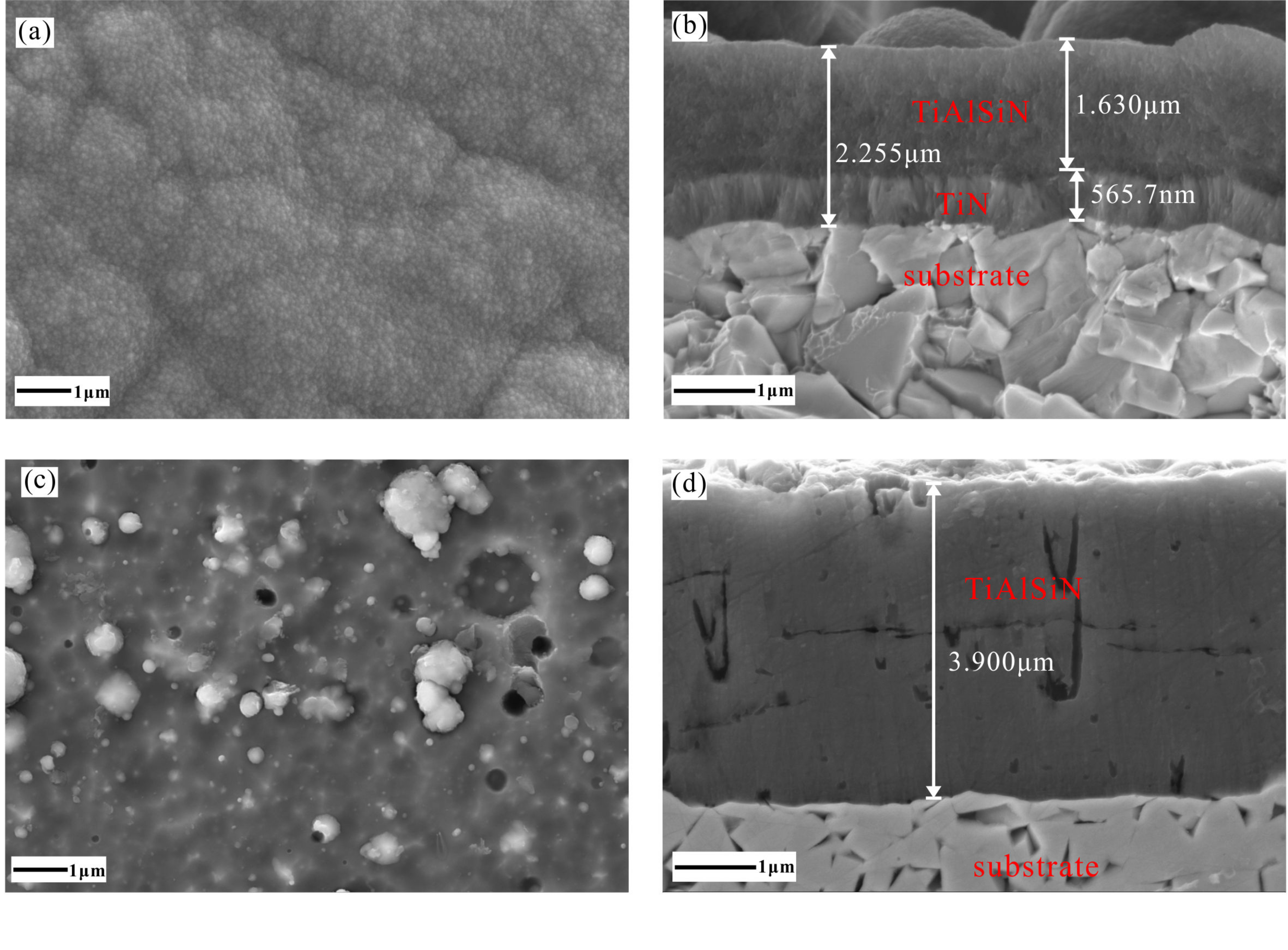
Figure 2 shows the FESEM micrographs of the as-deposited CVD Ti0.13Al0.85Si0.02N and PVD Ti0.31Al0.60Si0.09N coatings. Figure 2a,c display the surface microstructure of as-deposited CVD Ti0.13Al0.85Si0.02N and PVD Ti0.31Al0.60Si0.09N coatings. It is obvious that Ti0.13Al0.85Si0.02N coating prepared using the LPCVD method exhibits a featureless morphology, while PVD Ti0.31Al0.60Si0.09N coating includes many shallow pits and irregular particles on the surface, which is a typical surface morphology feature of coating prepared using multi arc ion plating technology [37]. The formation of particles is mainly due to the solidification of molten metal droplets on the coating surface. Under the negative bias, the particles with poor adhesion on the coating surface are peeled off by high energy ion bombardment, resulting in the formation of shallow pits.
Figure 2b,d present the cross-sectional micrographs of as-deposited CVD Ti0.13Al0.85Si0.02N and PVD Ti0.31Al0.60Si0.09N coatings, respectively. The TiN bonding layer with a thickness of 0.57 μm was found to be columnar in structure in CVD Ti0.13Al0.85Si0.02N coating. Meanwhile, the columnar structure disappeared and the formation of a featureless structure was observed in the TiAlSiN top-layer (see Figure 2b). In case of the PVD TiAlN coating, several groups of authors [38,39,40,41] have reported that PVD TiAlN coating exhibits a pronounced columnar structure. With the addition of Si into the TiAlN coating, the amorphous structure SiNx is formed, which will wrap around the TiAlN grains and make the grains unable to grow and force TiAlN to nucleate continuously. As a result, the grains of TiAlSiN coating are refined and the columnar grains disappear, showing a cross-section structure similar to amorphous state [26,42]. The cross-section morphology of PVD Ti0.31Al0.60Si0.09N was in agreement with that from the literature [26]. In addition, compared with Figure 2b, some micro particles which originate in the arc process at the target side appear in the PVD TiAlSiN coating. Compared with the PVD TiAlSiN coating, the CVD coating has an additional TiN layer, which resulted in a more obvious TiN peak identified in the CVD coating (see Figure 1).
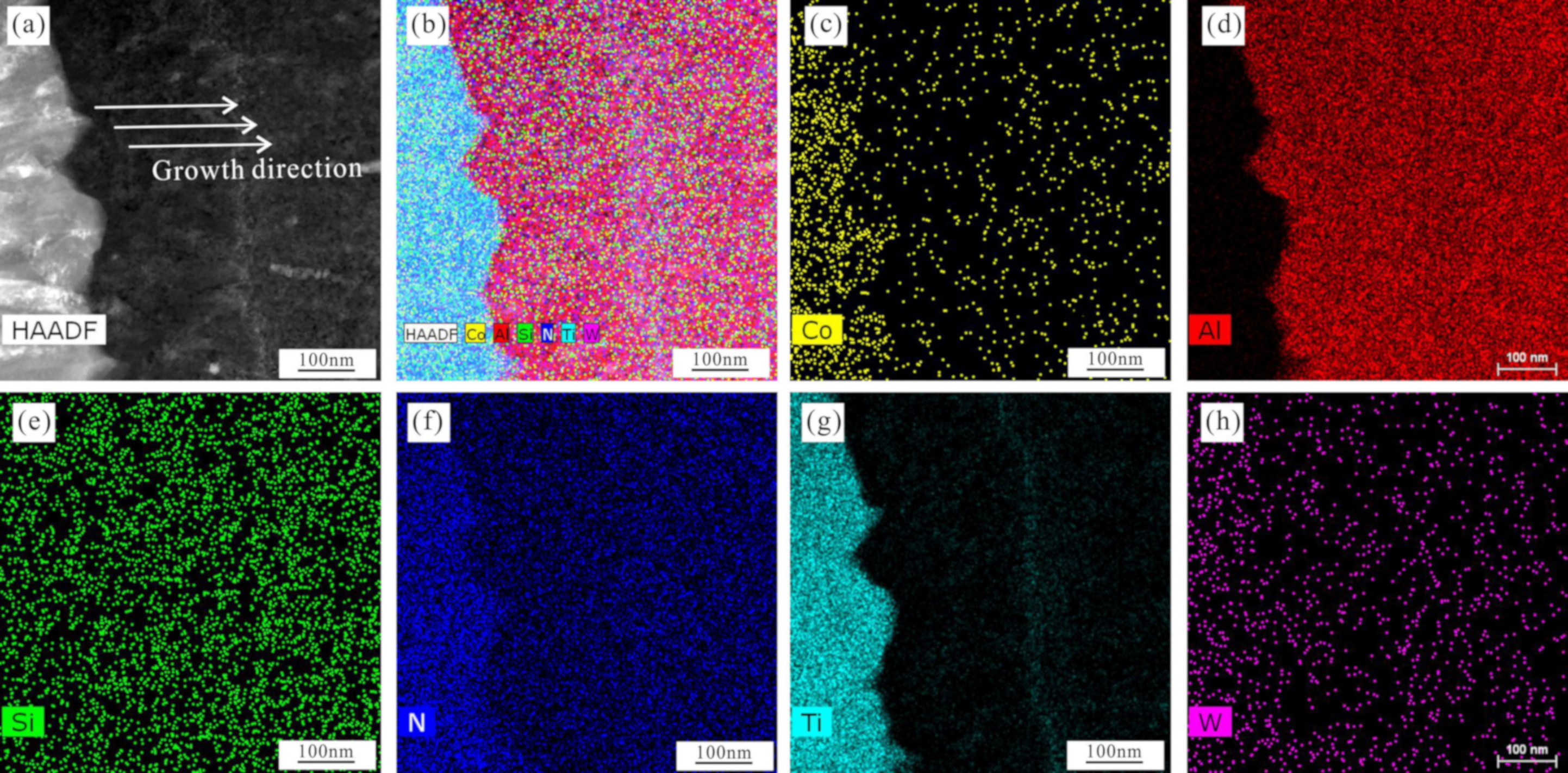
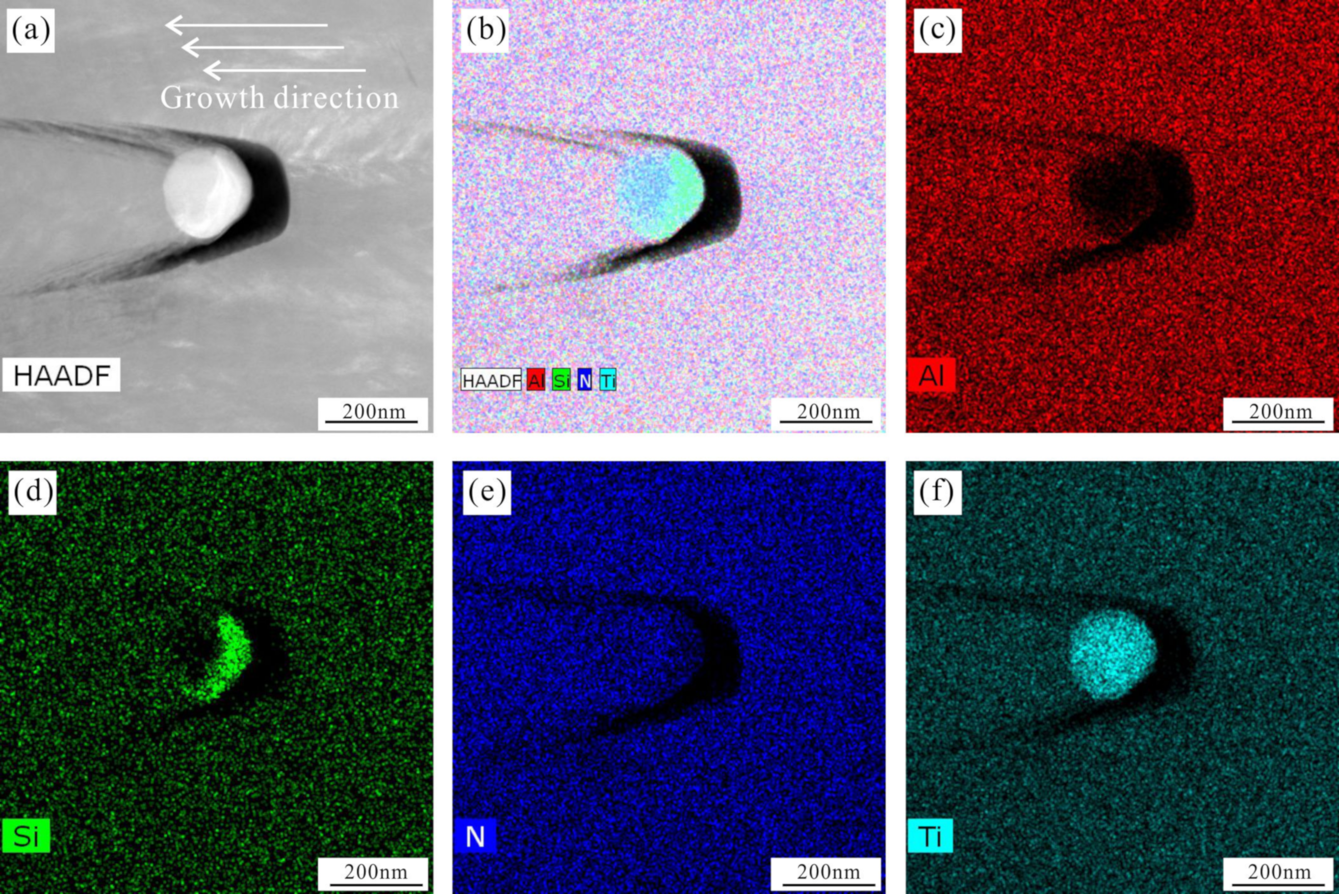
TEM investigations were employed in order to compare the microstructure of the CVD Ti0.13Al0.85Si0.02N and PVD Ti0.31Al0.60Si0.09N coatings obtained from the present work. Figure 3 and Figure 4 present the HAADF–STEM images and EDS mappings of two different kinds of TiAlSiN coatings, respectively. It can be found from mapping images that Ti and N are uniformly distributed mainly in the first layer with light gray contrast, and Ti, Al, Si, and N are uniformly distributed in the second layer with dark gray contrast. The results indicate that the CVD Ti0.13Al0.85Si0.02N coating is composed of a TiN bonding layer and a TiAlSiN layer, which is consistent with the FESEM result that can be seen in Figure 2. Otherwise, we also found that the element Co was distributed into the first layer, which is caused by the high deposition temperature of CVD method and the rapid diffusion of Co. For PVD Ti0.31Al0.60Si0.09N coating, Figure 4 indicates that there are some pores existing in the coatings and Ti and Si are enriched in the micro particles near the pores. Chen et al. [37] suggest that the growth defects of metallic macro-particles on the coating surface are caused by the difference of melting points for Al, Ti, and Si, where alloying with Si causes an apparent increase in growth defects of metallic macro-particles. As a result, it can be roughly inferred that the enrichment of Ti and Si around the pores is caused by TiSi alloying brought about by arc ion plating technology. In other areas, the four elements are evenly distributed.
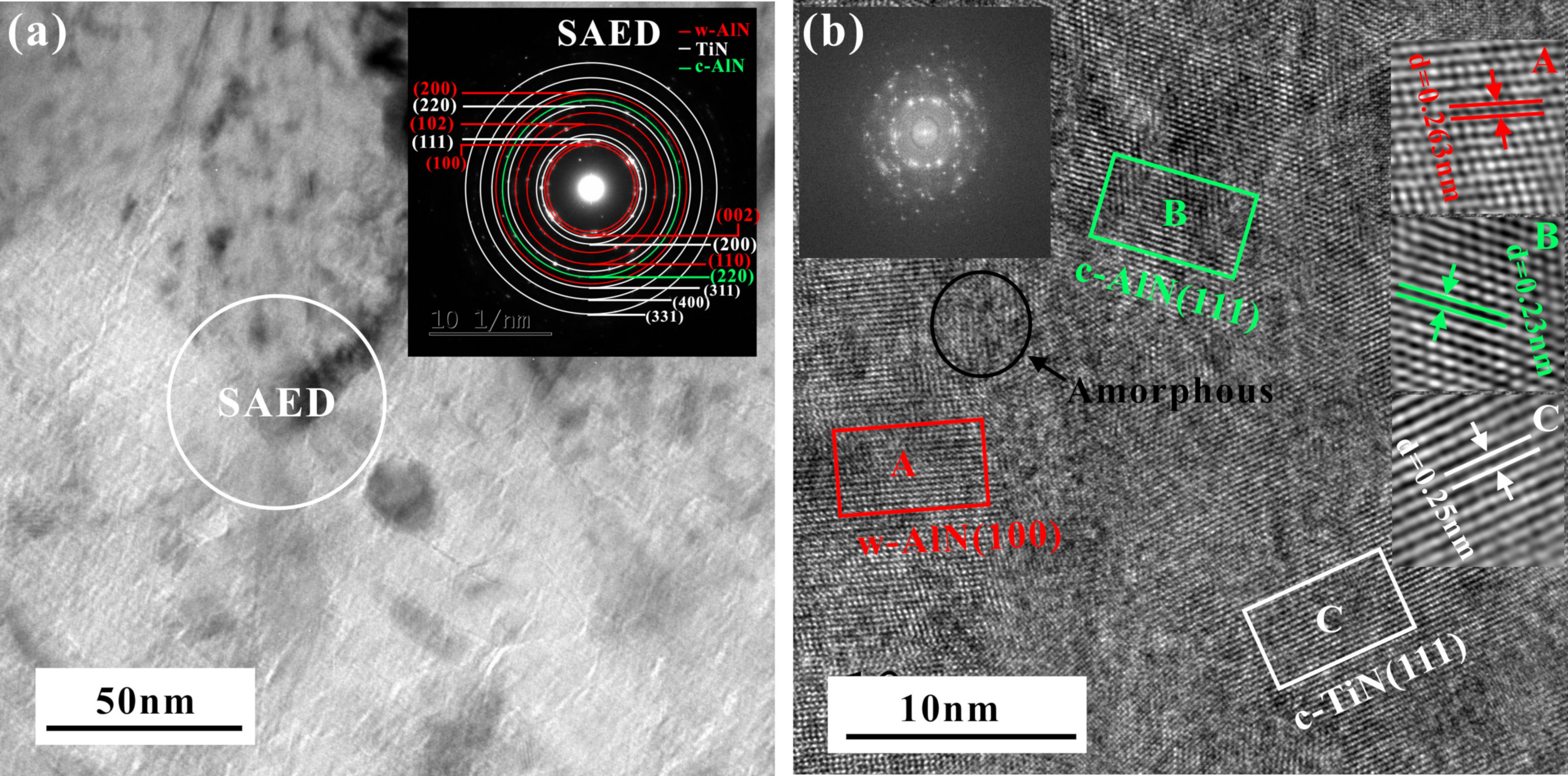
Bright field images of the CVD Ti0.13Al0.85Si0.02N coating, including an insert of the corresponding SAED pattern and high-resolution TEM with an insert of the corresponding fast Fourier transformation (FFT) images are shown in Figure 5a,b. From the SAED pattern (Figure 5a), (111), (200), (220), (311), (400), and (331) reflections of c-TiN phase, (100), (002), (102), (110), and (200) reflections of w-AlN phase and (220) reflection of c-AlN phase could be identified, which was well compatible with the XRD patterns of Figure 1. There is no information corresponding to the SiNx crystalline from the SAED patterns. Nevertheless, the amorphous ring observed in fast Fourier transform in Figure 5b can still indicate the existence of amorphous SiNx. From the fast Fourier transformation (FFT) images in Figure 5b, we can see that the interplanar spacing of A is 2.63 Å which is close to that of w-AlN (100) plane (2.695 Å according to JCPDS 25-1133). Therefore, region A in Figure 5b is believed to be (100) planes of w-AlN. The interplanar spacing for region B and C is 2.30 Å and 2.50 Å, respectively, while the interplanar spacing of c-AlN and TiN (111) planes is 2.2736 Å and 2.4492 Å (c-AlN, JCPDS 46-1200 and TiN, JCPDS 38-1420). In addition, the area within the black circle does not have the characteristics of a crystalline structure, so it should be amorphous SiNx. Thus, the CVD Ti0.13Al0.85Si0.02N coating was composed of some nano-crystallines and amorphous structures. Meanwhile, the nanocrystals were embedded in the amorphous matrix, which was similar to the results for PVD TiAlSiN coatings [28,43].
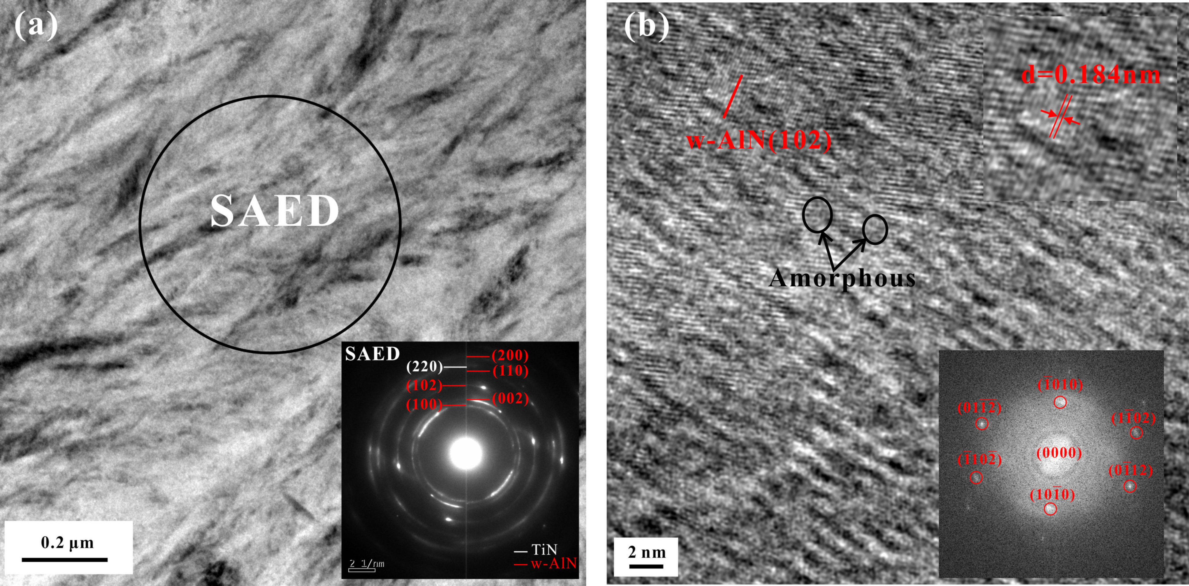
Figure 6 presents the cross-sectional TEM micrograph, fast Fourier transformation (FFT) image, and selected area electron diffraction (SAED) pattern of PVD Ti0.31Al0.60Si0.09N coating. The SAED pattern (Figure 6a) corresponds to the c-TiN and w-AlN structure. In the HRTEM image (Figure 6b), it can be seen that the size of amorphous SiNx (circled by black circles) is between 1 and 3 nm. Meanwhile, the possibility that Si atoms are accommodated in the (Ti, Al, Si)N solid solution was not ruled out, since Si atoms exists in the solid solution in TiSiN, TiSiCN, and other coatings [12,44,45]. This proved that the structure of TiAlSiN is a kind of nano-composite structure, in which the amorphous SiNX matrix contains nano-crystals.

3.3. Mechanical Properties of the As-Deposited CVD TiAlSiN and PVD TiAlSiN Coatings

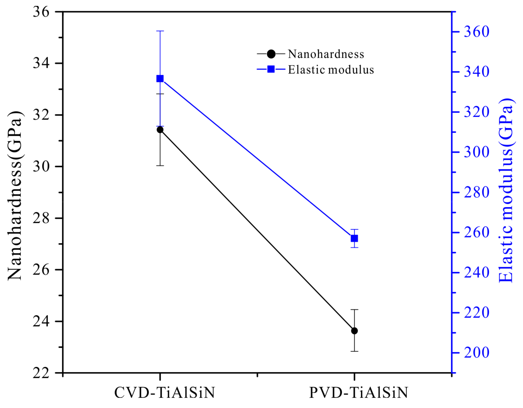
The hardness (H) and effective elastic modulus (E*) were measured by nanoindentation. Moreover, the elastic modulus (E) was calculated using the formula of E* = E/(1 − ν2), where ν is the Poisson’s ratio [46,47]. Figure 7 manifests the nano-hardness of CVD Ti0.13Al0.85Si0.02N and PVD Ti0.31Al0.60Si0.09N coating. The hardnesses of CVD Ti0.13Al0.85Si0.02N and PVD Ti0.31Al0.60Si0.09N coating were 31.7 ± 1.4 GPa and 23.5 ± 0.8 GPa, respectively. The result shows that the hardness of the CVD TiAlSiN coating was significantly higher than that of PVD TiAlSiN coating, which is related to the higher Si content in PVD coating. Higher Si element content coating leads PVD coating to form a higher content of amorphous phase in the coating, as a result, the excessive amount of amorphous phase will decrease the hardness of the coating. In addition, the higher Al content in the CVD coating contributes to the formation of face centered c-AlN phase in the coating, and the increase of the face-centered cubic structure in the coating is conducive to the increase of hardness of the coating.
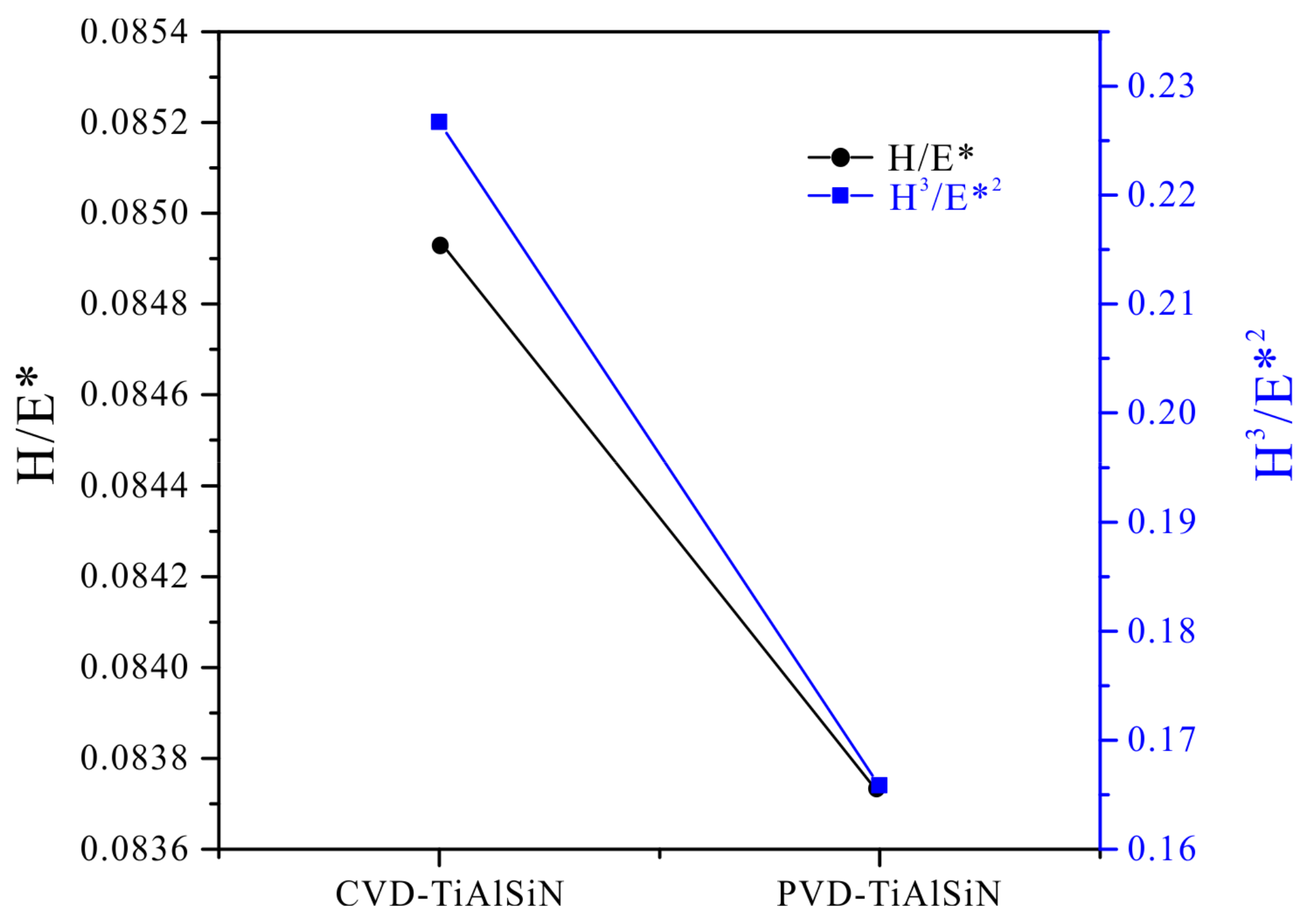
With the aim of comparing the toughness of two kinds of different coatings, H/E (a description in terms of ‘elastic strain to failure’) and H3/E*2 (a indicator of a surface’s resistance to plastic deformation) [48,49,50] were employed to characterize the resistance against the elastic strain and plastic deformation, respectively. Figure 8 displays the H/E* and H3/E*2 ratios of the TiAlSiN coating deposited with different methods. The results point out that the ratios of H/E* and H3/E*2 of CVD Ti0.13Al0.85Si0.02N coating reached the maximum value (0.085 and 0.227). Since a higher H/E* and H3/E*2 ratio means good toughness, the CVD TiAlSiN coating obtained in this work can have both higher hardness and toughness, which also means that the CVD coating could be widely applied in industry.

4. Conclusions

Ti0.13Al0.85Si0.02N and Ti0.31Al0.60Si0.09N coatings were deposited on cemented carbide substrate using the chemical vapor deposition and arc ion plating methods, respectively. XRD, FIB-SEM, TEM, and Nano-indenter were employed to study the effect of deposition method on microstructure and mechanical properties of TiAlSiN coating. The main conclusions of this work are summarized below.
The CVD Ti0.13Al0.85Si0.02N coating was composed of c-AlN, c-TiN phases, and a dominant amount of w-AlN according to the XRD patterns. In the PVD Ti0.31Al0.60Si0.09N coating, only the peak of w-AlN could be clearly observed apart from the peaks of matrix phase.
The CVD Ti0.13Al0.85Si0.02N coating exhibited a featureless morphology, while the PVD Ti0.31Al0.60Si0.09N coating had shallow pits and irregular particles on the surface, based on the SEM images. In addition, the cross-sections of these two coatings show a typical amorphous structure.
TEM analysis illustrated that these two coatings consist of a nanocrystalline embedded in amorphous SiNx.
The CVD Ti0.13Al0.85Si0.02N coating not only had higher hardness and Young’s modulus than the PVD Ti0.31Al0.60Si0.09N coating, but also has higher H/E* and H3/E*2 values than the PVD Ti0.31Al0.60Si0.09N coating. Therefore, we conclude that the CVD TiAlSiN coating has the better wear resistance, fracture toughness, and plastic deformation resistance compared to the PVD TiAlSiN coating.

Author Contributions

Conceptualization, L.W.; methodology, L.W.; software, L.W.; validation, L.W.; formal analysis, L.W. and L.Q.; investigation, L.W., F.Z., L.C. and J.Z.; resources, L.W.; data curation, L.W., L.Q., Q.L. and L.Y.; writing—original draft preparation, L.W.; writing—review and editing, L.W., L.Q., Y.D. and Z.T.; visualization, L.W.; supervision, Y.D.; project administration, Y.D. and Z.T.; funding acquisition, Y.D. and Z.T. All authors have read and agreed to the published version of the manuscript.

Funding

The research was funded by Key R&D program of Science and Technology Department of Jiangxi Province in China, grant number No. 20192ACB80010 and National Natural Science Foundation of China, grant number No. 52031017.

Data Availability Statement

The data presented in this study are available on request from the corresponding author.

Acknowledgments

The authors appreciate Ganzhou Achteck Tool Technology Co., Ltd of China for providing the coating samples.

Conflicts of Interest

The authors declare no conflict of interest.

References

  1. Shao, L.J. Study on oxidation resistant behavior at high-temperature on TiN, TiAlN coaatings prepared by unbalanced magnetron sputtering. Hot Work. Technol. 2009, 38, 93–95. (In Chinese) [Google Scholar] [CrossRef]
  2. Anderbouhr, S.; Ghetta, V.; Blanquet, E.; Chabrol, C.; Schuster, F.; Bernard, C.; Madar, R. LPCVD and PACVD (Ti,Al)N films: Morphology and mechanical properties. Surf. Coat. Technol. 1999, 115, 103–110. [Google Scholar] [CrossRef]
  3. Todt, J.; Pitonak, R.; Köpf, A.; Weißenbacher, R.; Sartory, B.; Burghammer, M.; Daniel, R.; Schöberl, T.; Keckes, J. Superior oxidation resistance, mechanical properties and residual stresses of an Al-rich nanolamellar Ti0.05Al0.95N coating prepared by CVD. Surf. Coat. Technol. 2014, 258, 1119–1127. [Google Scholar] [CrossRef]
  4. Keckes, J.; Daniel, R.; Mittere, C.r.; Matko, I.; Sartory, B.; Koepf, A.; Weißenbacher, R.; Pitonak, R. Self-organized periodic soft-hard nanolamellae in polycrystalline TiAlN thin films. Thin Solid Films 2013, 545, 29–32. [Google Scholar] [CrossRef]
  5. Todt, J.; Zalesak, J.; Daniel, R.; Pitonak, R.; Köpf, A.; Weißenbacher, R.; Sartory, B.; Mitterer, C.; Keckes, J. Al-rich cubic Al0.8Ti0.2N coating with self-organized nano-lamellar microstructure: Thermal and mechanical properties. Surf. Coat. Technol. 2016, 291, 89–93. [Google Scholar] [CrossRef]
  6. Endler, I.; Höhn, M.; Herrmann, M.; Pitonak, R.; Ruppi, S.; Schneider, M.; van den Berg, H.; Westphal, H. Novel aluminum-rich Ti1-xAlxN coatings by LPCVD. Surf. Coat. Technol. 2008, 203, 530–533. [Google Scholar] [CrossRef]
  7. Ahmed, M.S.; Munroe, P.; Jiang, Z.T.; Zhao, X.; Rickard, W.; Zhou, Z.F.; Li, L.K.Y.; Xie, Z. Corrosion behaviour of nanocomposite TiSiN coatings on steel substrates. Corros. Sci. 2011, 53, 3678–3687. [Google Scholar] [CrossRef] [Green Version]
  8. Dang, C.; Li, J.; Wang, Y.; Chen, J. Structure, mechanical and tribological properties of self-toughening TiSiN/Ag multilayer coatings on Ti6Al4V prepared by arc ion plating. Appl. Surf. Sci. 2016, 386, 224–233. [Google Scholar] [CrossRef]
  9. Wan, Q.; Ding, H.; Yousaf, M.; Chen, Y.; Liu, H.; Hu, L.; Yang, B. Corrosion behaviors of TiN and Ti-Si-N (with 2.9 at.% and 5.0 at.% Si) coatings by electrochemical impedance spectroscopy. Thin Solid Films 2016, 616, 601–607. [Google Scholar] [CrossRef]
  10. Zhang, M.; Ma, S.; Xu, K.; Bai, L.; Chu, P.K. Bio-tribological properties and cyto-compatibility of Ti-Si-N coatings. Vacuum 2015, 115, 50–57. [Google Scholar] [CrossRef]
  11. Qiu, L.C.; Du, Y.; Wang, S.Q.; Li, K.; Yin, L.; Wu, L.Y.; Zhong, Z.Q.; Albir, L. Mechanical properties and oxidation resistance of chemically vapor deposited TiSiN nanocomposite coating with thermodynamically designed compositions. Int. J. Refract. Met. Hard Mater. 2019, 80, 30–39. [Google Scholar] [CrossRef]
  12. Carvalho, S.; Rebouta, L.; Ribeiro, E.; Vaz, F.; Denannot, M.F.; Pacaud, J.; Riviere, J.P.; Paumier, F.; Gaboriaud, R.J.; Alves, E. Microstructure of (Ti,Si,Al)N nanocomposite coatings. Surf. Coat. Technol. 2004, 177–178, 369–375. [Google Scholar] [CrossRef]
  13. Barshilia, H.C.; Ghosh, M.; Shashidhara; Ramakrishna, R.; Rajam, K.S. Deposition and characterization of TiAlSiN nanocomposite coatings prepared by reactive pulsed direct current unbalanced magnetron sputtering. Appl. Surf. Sci. 2010, 256, 6420–6426. [Google Scholar] [CrossRef]
  14. Liang, F.; Wang, H.J.; Zou, C.W. Effects of ion source voltages on the composition, hardness, and temperature-dependent tribological properties of Ti-Al-Si-N nanocomposite coatings. Jpn. J. Appl. Phys. 2014, 53, 075503. [Google Scholar] [CrossRef]
  15. Carvalho, S.; Rebouta, L.; Cavaleiro, A.; Rocha, L.A.; Gomes, J.; Alves, E. Microstructure and mechanical properties of nanocomposite (Ti,Si,Al)N coatings. Thin Solid Films 2001, 398–399, 391–396. [Google Scholar] [CrossRef]
  16. Gao, F.Y.; Li, G.; Xia, Y. Influence of hysteresis effect on properties of reactively sputtered TiAlSiN films. Appl. Surf. Sci. 2018, 431, 160–164. [Google Scholar] [CrossRef] [Green Version]
  17. Carvalho, S.; Rebouta, L.; Ribeiro, E.; Vaz, F.; Tavares, C.J.; Alves, E.; Barradas, N.P.; Riviere, J.P. Structural evolution of Ti–Al–Si–N nanocomposite coatings. Vacuum 2009, 83, 1206–1212. [Google Scholar] [CrossRef] [Green Version]
  18. Kim, S.K.; Vinh, P.V.; Kim, J.H.; Ngoc, T. Deposition of superhard TiAlSiN thin films by cathodic arc plasma deposition. Surf. Coat. Technol. 2005, 200, 1391–1394. [Google Scholar] [CrossRef]
  19. Liu, J.; Zhu, S.S.; Deng, X.; Liu, J.Y.; Wang, Z.P.; Qu, Z. Cutting Performance and Wear Behavior of AlTiN- and TiAlSiN-Coated Carbide Tools During Dry Milling of Ti–6Al–4V. Acta Metall. Sin. Eng. Lett. 2020, 33, 135–146. [Google Scholar] [CrossRef] [Green Version]
  20. Lee, J.H.; Oh, I.H.; Jang, J.H.; Kim, J.H.; Hong, S.K.; Park, H.K. Influence of Phase Composition in TiAlSiN Hard Coatings on the Evolution of Structure and Mechanical Properties. Met. Mater. Int. 2020, 1–11. [Google Scholar] [CrossRef]
  21. Wang, M.C.; Wang, L.J.; Chen, H.; Cheng, Y.F. Study on the phase structure and mechanical properties of (Ti,Al,Si)N coatings deposited by multiarc ion plating. Int. J. Mod. Phys. B 2020, 34, 2040043. [Google Scholar] [CrossRef]
  22. Song, Z.H.; Dai, M.J.; Li, H.; Hong, Y.; Lin, S.S.; Shi, Q.; Su, Y.F. Effect of Arc Ion Plating Bias on Structure and Properties of TiAlSiN Films. Surface Technol. 2020, 49, 306–314. (In Chinese) [Google Scholar] [CrossRef]
  23. Rafaja, D.; Poklad, A.; Klemm, V.; Schreiber, G.; Heger, D.; Šíma, M.; Dopita, M. Some consequences of the partial crystallographic coherence between nanocrystalline domains in Ti–Al–N and Ti–Al–Si–N coatings. Thin Solid Films 2016, 514, 240–249. [Google Scholar] [CrossRef]
  24. Chen, L.; Du, Y.; Wang, A.J.; Wang, S.Q.; Zhou, S.Z. Effect of Al content on microstructure and mechanical properties of Ti–Al–Si–N nanocomposite coatings. Int. J. Refract. Met. Hard Mater. 2009, 27, 718–721. [Google Scholar] [CrossRef]
  25. Chang, C.L.; Lee, J.W.e.i.; Tseng, M.D. Microstructure, corrosion and tribological behaviors of TiAlSiN coatings deposited by cathodic arc plasma deposition. Thin Solid Films 2009, 517, 5231–5236. [Google Scholar] [CrossRef]
  26. Chen, L.; Wang, S.Q.; Du, Y.; Zhou, S.Z.; Gang, T.; Fen, J.C.; Chang, K.K.; Li, Y.W.; Xiong, X. Machining performance of Ti–Al–Si–N coated inserts. Surf. Coat. Technol. 2010, 205, 582–586. [Google Scholar] [CrossRef]
  27. Flink, A.; Andersson, J.; Alling, B.; Daniel, R.; Sjölén, J.; Karlsson, L.; Hultman, L. Structure and thermal stability of arc evaporated (Ti0.33Al0.67)1-xSixN thin films. Thin Solid Films 2008, 517, 714–721. [Google Scholar] [CrossRef] [Green Version]
  28. Chang, Y.Y.; Lai, H.M. Wear behavior and cutting performance of CrAlSiN and TiAlSiN hard coatings on cemented carbide cutting tools for Ti alloys. Surf. Coat. Technol. 2014, 259, 152–158. [Google Scholar] [CrossRef]
  29. Park, I.W.; Choi, S.R.; Suh, J.H.; Park, C.G.; Kim, K.H. Deposition and mechanical evaluation of superhard Ti-Al-Si-N nanocomposite films by a hybrid coating system. Thin Solid Films 2004, 447–448, 443–448. [Google Scholar] [CrossRef]
  30. Du, H.; Zhao, H.B.; Xiong, J.; Xian, G. Effect of interlayers on the structure and properties of TiAlN based coatings on WC-Co cemented carbide substrate. Int. J. Refract. Met. Hard Mater. 2013, 37, 60–66. [Google Scholar] [CrossRef]
  31. Yu, D.H.; Wang, C.Y.; Cheng, X.L.; Zhang, F.L. Microstructure and properties of TiAlSiN coatings prepared by hybrid PVD technology. Thin Solid Films 2009, 517, 4950–4955. [Google Scholar] [CrossRef]
  32. Li, Y.S.; Shimada, S.; Kiyono, H.; Hirose, A. Synthesis of Ti-Al-Si-N nanocomposite films using liquid injection PECVD from alkoxide precursors. Acta Mater. 2006, 54, 2041–2048. [Google Scholar] [CrossRef]
  33. Das, S.; Guha, S.; Ghadai, R.; Swain, B.P. A comparative analysis over different properties of TiN, TiAlN and TiAlSiN thin film coatings grown in nitrogen gas atmosphere. Mater. Chem. Phys. 2021, 258, 123866. [Google Scholar] [CrossRef]
  34. Zou, C.W.; Zhang, J.; Xie, W.; Shao, L.X.; Guo, L.P.; Fu, D.J. Characterization and properties Ti-Al-Si-N nanocomposite coatings prepared by middle frequency magnetron sputtering. Appl. Surf. Sci. 2011, 257, 10373–10378. [Google Scholar] [CrossRef]
  35. Zhao, F.; Wang, L.P.; Wang, X.F. Microstructure and properties of TiAlSiN ultra-hard coatings prepared by plasma immersion ion implantation and deposition with TiAlSi alloy cathodes. Vacuum 2020, 174, 109194. [Google Scholar] [CrossRef]
  36. Niederhofer, A.; Nesládek, P.; Männling, H.-D.; Moto, K.; Veprek, S.; Jĭlek, M. Structural properties, internal stress and thermal stability of nc-TiN/a-Si3N4, nc-TiN/TiSix and nc-(Ti1−yAlySix)N superhard nanocomposite coatings reaching the hardness of diamond. Surf. Coat. Technol. 1999, 120–121, 173–178. [Google Scholar] [CrossRef]
  37. Chen, L.; Yang, B.; Xu, Y.X.; Pei, F.; Zhou, L.C.; Du, Y. Improved thermal stability and oxidation resistance of Al-Ti-N coating by Si addition. Thin Solid Films 2014, 556, 369–375. [Google Scholar] [CrossRef]
  38. Coll, B.F.; Fontana, R.; Gates, A.; Sathrum, P. (Ti,Al)N advanced films prepared by arc process. Mater. Sci. Eng. A 1991, 140, 816–824. [Google Scholar] [CrossRef]
  39. Suzuki, T.; Huang, D.; Ikuhara, Y. Microstructures and grain boundaries of (Ti,Al)N films. Surf. Coat. Technol. 1998, 107, 41–47. [Google Scholar] [CrossRef]
  40. Jindal, P.C.; Santhanam, A.T.; Schleinkofer, U.; Shuster, A.F. Performance of PVD TiN, TiCN, and TiAlN coated cemented carbide tools in turning. Int. J. Refract. Met. Hard Mater. 1999, 17, 163–170. [Google Scholar] [CrossRef]
  41. Kimura, A.; Hasegawa, H.; Yamada, K.; Suzuki, T. Metastable Ti1-xAlxN films with different Al content. J. Mater. Sci. Lett. 2000, 19, 601–602. [Google Scholar] [CrossRef]
  42. Zou, L.L. Study on Properties of Nano-multilayer TiAlSiN Coating Prepared by Multi-arc Ion Plating. Mech. Eng. 2018, 8, 98–100. (In Chinese) [Google Scholar] [CrossRef]
  43. Parlinska-Wojtan, M.; Karimi, A.; Cselle, T.; Morstein, M. Conventional and high resolution TEM investigation of the microstructure of compositionally graded TiAlSiN thin films. Surf. Coat. Technol. 2004, 177–178, 376–381. [Google Scholar] [CrossRef]
  44. Zhang, Y.J.; Yang, Y.Z.; Ding, H.W.; Peng, Y.; Zhang, S.M.; Yu, L.G.; Zhang, P.Y. Combining magnetic filtered cathodic arc deposition with ion beam sputtering to afford superhard TiSiN multilayer composite fifilms with tunable microstructure and mechanical properties. Vacuum 2016, 125, 6–12. [Google Scholar] [CrossRef]
  45. Guo, Y.; Ma, S.L.; Xu, K.W. On the oxidation resistance of superhard Ti–Si–C–N coatings. J. Mater. Res. 2008, 23, 2420–2428. [Google Scholar] [CrossRef]
  46. Zhang, S.; Sun, D.; Fu, Y.; Du, H. Toughening of hard nanostructural thin films: A critical review. Surf. Coat. Technol. 2005, 198, 2–8. [Google Scholar] [CrossRef]
  47. Liu, H.; Yang, F.C.; Tsai, Y.J.; Wang, X.; Li, W.; Chang, C.L. Effect of modulation structure on the microstructural and mechanical properties of TiAlSiN/CrN thin films prepared by high power impulse magnetron sputtering. Surf. Coat. Technol. 2019, 358, 577–585. [Google Scholar] [CrossRef]
  48. Ou, Y.X.; Lin, J.; Tong, S.; Che, H.L.; Sproul, W.D.; Lei, M.K. Wear and corrosion resistance of CrN/TiN superlattice coatings deposited by a combined deep oscillation magnetron sputtering and pulsed dc magnetron sputtering. Appl. Surf. Sci. 2015, 351, 332–343. [Google Scholar] [CrossRef]
  49. Leyland, A.; Matthews, A. On the significance of the H/E ratio in wear control: A nanocomposite coating approach to optimised tribological behavior. Wear 2000, 246, 1–11. [Google Scholar] [CrossRef]
  50. Leyland, A.; Matthews, A. Optimization of Nanostructured Tribological Coatings. In Nanostructured Coatings: Nanostructure Science and Technology; Cavaleiro, A., De Hosson, J.T.M., Eds.; Springer Science + Business Media LLC: New York, NY, USA, 2006; pp. 511–538. [Google Scholar] [CrossRef]
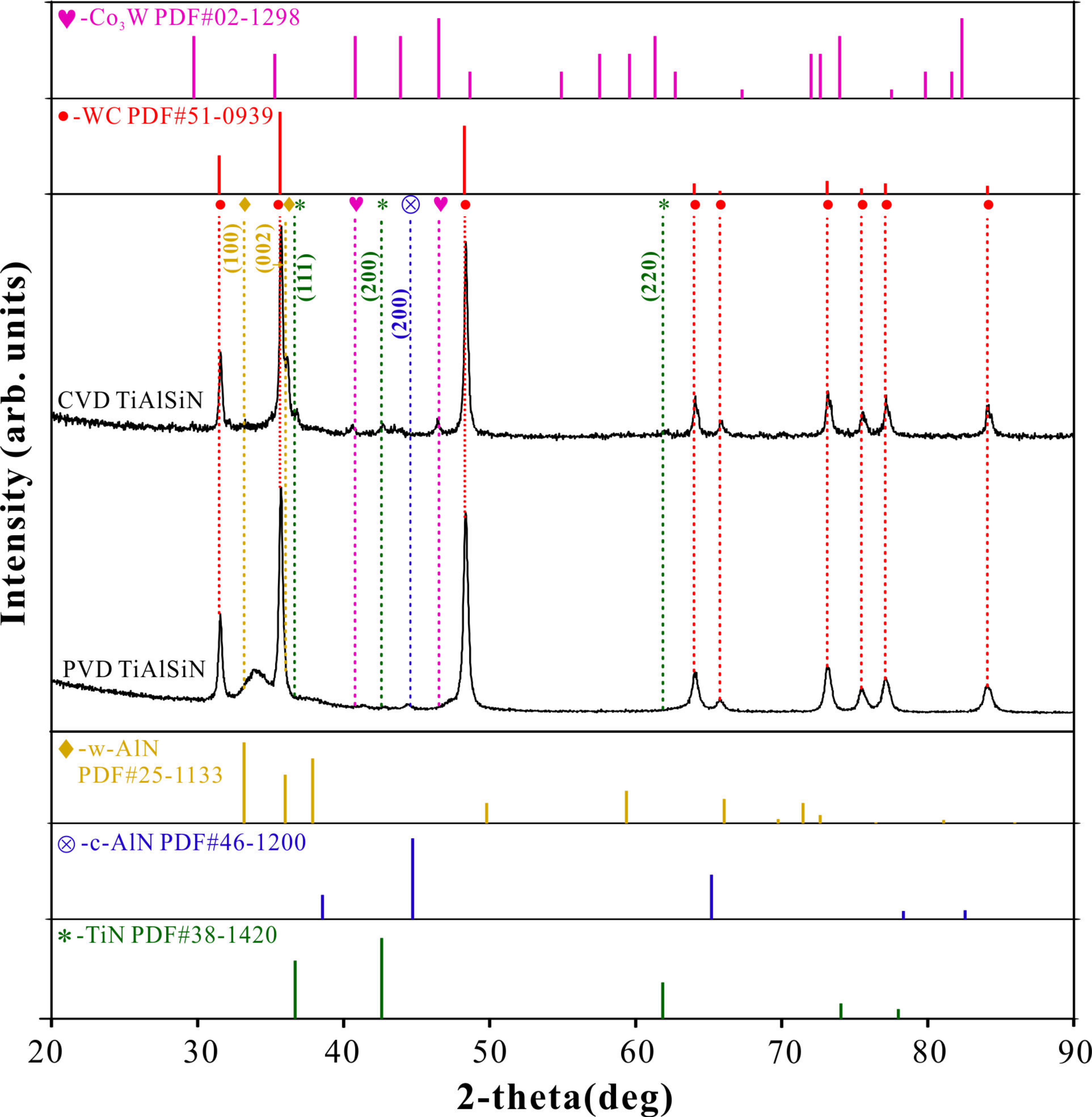
Figure 1. XRD patterns of as-deposited CVD Ti0.13Al0.85Si0.02N coating and PVD Ti0.31Al0.60Si0.09N coating.
Crystals 11 00598 g001
Figure 2. FESEM micrographs of two different coatings: (a) CVD Ti0.13Al0.85Si0.02N, surface; (b) CVD Ti0.13Al0.85Si0.02N, cross-section; (c) PVD Ti0.31Al0.60Si0.09N, surface; (d) PVD Ti0.31Al0.60Si0.09N, cross-section.
Crystals 11 00598 g002
Figure 3. (a) HAADF–STEM image of CVD Ti0.13Al0.85Si0.02N coating and EDS mapping images for distribution of (b) Co, Al, Si, N, Ti and W; (c) Co; (d) Al; (e) Si; (f) N; (g) Ti; (h) W in CVD Ti0.13Al0.85Si0.02N coating.
Crystals 11 00598 g003
Figure 4. (a) HAADF–STEM image of PVD Ti0.31Al0.60Si0.09N coating and EDS mapping images for distribution of (b) Al, Si, N and Ti; (c) Al; (d) Si; (e) N; (f) Ti in PVD Ti0.31Al0.60Si0.09N coating.
Crystals 11 00598 g004
Figure 5. Cross-sectional TEM images of CVD Ti0.13Al0.85Si0.02N coating. (a) A bright field TEM image with an SAED pattern in the inset and (b) HRTEM image and FFT pattern of the coating.
Crystals 11 00598 g005
Figure 6. Cross-sectional TEM images of PVD Ti0.31Al0.60Si0.09N coatings. (a) A bright field TEM image with an SAED pattern in the inset and (b) HRTEM image and FFT pattern of the coating.
Crystals 11 00598 g006
Figure 7. The hardness and elastic modulus of CVD Ti0.13Al0.85Si0.02N and PVD Ti0.31Al0.60Si0.09N coatings.
Crystals 11 00598 g007
Figure 8. The H/E* and H3/E*2 ratios of of CVD Ti0.13Al0.85Si0.02N and PVD Ti0.31Al0.60Si0.09N coatings.
Crystals 11 00598 g008
Table 1. Compositions of CVD and PVD TiAlSiN coatings (at%).
LayerTi (at.%)Al (at.%)Si (at.%)N (at.%)Cl (at.%)C (at.%)W (at.%)Co (at.%)Sum (at.%)
CVD-TiAlSiN7.4540.040.9950.071.24/0.21/100
CVD-TiN30.2510.31 /37.920.5716.923.650.39100
PVD-TiAlSiN15.5230.104.4249.96////100
Publisher’s Note: MDPI stays neutral with regard to jurisdictional claims in published maps and institutional affiliations.