Article

Effects of Polarity Inversion Layer on Performances of Lateral-Field-Excitation Piezoelectric Sensors Based on Lithium Niobate Single Crystal

1
Piezoelectric Device Laboratory, School of Mechanical Engineering and Mechanics, Ningbo University, Ningbo 315211, China
2
School of Civil and Environment Engineering, Ningbo University, Ningbo 315211, China
3
Department of Architectural Engineering, Ningbo Polytechnic, Ningbo 315800, China
*
Author to whom correspondence should be addressed.
Crystals 2021, 11(4), 407; https://doi.org/10.3390/cryst11040407
Submission received: 23 March 2021 / Revised: 8 April 2021 / Accepted: 9 April 2021 / Published: 11 April 2021

Abstract

:
In this work, lateral-field-excitation (LFE) piezoelectric sensors based on polarity inversion layer are designed and fabricated, then frequency stabilities and sensitivities on electric property changes of liquids are tested. Because the polarity inversion layer can suppress the spurious modes, the stabilities of the LFE devices with a polarity inversion layer are obviously better than that of LFE devices with no polarity inversion layer. On the changes of liquid conductivity and permittivity, the sensitivities of the LFE devices with a polarity inversion layer are 2.4 times and 2.1 times higher than that of LFE devices with no polarity inversion layer, respectively. The polarity inversion layer of the lithium niobate crystal plate can be realized conveniently by heat treatment, therefore, the technology of the polarity inversion layer can play an important role in improving the sensing performances of LFE sensors.

1. Introduction

In recent years, piezoelectric bulk acoustic wave devices have attracted much attention, which has been widely used for resonators, sensors, and transducers [1,2,3,4,5,6]. The excitation modes for piezoelectric bulk acoustic waves are divided into thickness field excitation (TFE) and lateral field excitation (LFE). The thickness field excitation mode was originally called vertical field excitation, in which two electrodes are placed on two parallel surfaces of the piezoelectric substrate and the electric field is perpendicular to the main surface of the piezoelectric substrate [7,8,9]. For the LFE mode [10,11,12], two electrodes of the device are placed on the same surface of the piezoelectric substrate, so the excitation electric field of the device is parallel to the surface of the piezoelectric substrate. The LFE device has the following advantages over the TFE device: the direction of the electric field can be altered by changing the orientation of the electrode tiled on the surface of the crystal plate, thus some unwanted vibration modes can be eliminated [13]; because there is a certain distance between two electrodes on the surface of the crystal plate, the aging rate of the device can be reduced; the sensitivities of changes in the electrical characteristics of analytes are higher [12,14]. These advantages are beneficial to the application of LFE devices in the field of resonators and sensors with high performance.
When the lithium niobate crystal is heated at a temperature of more than 1070 °C, the lithium ions will disperse and a gradient electric field is formed, which leads to the formation of the polarity inversion layer [15]. During the heating process, the inversion layer thickness continues to expand, and eventually stays in the middle layer of the substrate, thus forming an inversion layer with half the thickness of the piezoelectric crystal plate. In other words, half of the crystal plate close to the c+ plane is the crystal layer with polarity inversion, while the other half close to the c- plane is the crystal layer with no polarity inversion, as shown in Figure 1. Previous studies on the inversion layer technology have mainly focused on the thickness compressional wave mode, which is mainly applied in high-frequency ultrasonic transducers [16,17]. Compared with the conventional polarity layer, the piezoelectric constant with opposite sign can be obtained in the polarity inversion layer, which makes the strain direction formed on the polarity inversion layer opposite to that of the noninverting crystal layer. Therefore, odd and even harmonic modes can be excited simultaneously on the crystal with a polarity inversion layer, which enables the ultrasonic transducer to work at a higher bandwidth. In addition, the second harmonic mode formed by the polarity inversion layer has lower resonance impedance compared with the fundamental and third harmonic modes, which is of important application value for high-frequency piezoelectric crystal acoustic wave devices.
The influences of the polarity inversion layer on the frequency-impedance characteristics of piezoelectric devices were studied [18,19], and it was found that the even harmonics of thickness-shear modes could also be excited in the crystal plates with a polarity inversion layer. More importantly, the formation of the polarity inversion layer has a significant effect on suppressing spurious vibration modes of LFE devices [18], and it plays an important role in the optimization of thickness-shear-mode devices excited by a lateral electric field.
Frequency stabilities and sensitivities on electrical characteristic variations are two important performance parameters for LFE piezoelectric sensors. However, the effects of the polarity inversion layer on these properties are still unclear. In this study, the LFE piezoelectric sensors based on the polarity inversion layer are designed and fabricated. Then for the devices, the frequency stabilities and the sensitivities to the changes of the conductivity and dielectric characteristics of the liquid are tested.

2. Experiments and Test Methods

A (yxl) 21.82° LiNbO3 crystal plate was selected to fabricate LFE sensors. According to Euler, angles for (yxl) 21.82 are 0°, 111.82°, and 0°. The crystal was processed into wafer with a thickness of 0.367 mm, and then the crystal plate was processed by polarity inversion layer technology [18]. Steps are as follows: (1) to place the crystal plate in a high-temperature furnace (HTRV-100-250, Nabertherm, Germany); (2) to heat the crystal plate at a rate of 4.77 °C/min for 4 h to 1170 °C; (3) to cool the furnace at 9.54 °C /min for 2 h, returning to room temperature, and take out the crystal plate. The electrodes were fabricated by the vacuum evaporation method. In order to enhance the adhesion of the gold electrode on the crystal surface, a layer of chromium with a thickness of about 2 nm was first plated, and then a gold electrode with a thickness of 200 nm was plated. After evaporation, in order to improve the electrode adhesion, the devices were baked at 200 °C for 2 h. The fabricated LFE device is shown in Figure 2, which operates in thickness-shear mode. In this work, the series resonance of LFE devices is considered.
In order to test the sensor performances conveniently, the experimental platform was built, as shown in Figure 3. The sensor was fixed in a special clamp so that the electrodeless side of the crystal is exposed. It was then placed in the solution under test, and a magnetic stirrer was used to ensure the uniformity of the solution. The sensor was connected with a resonance frequency detector of bulk acoustic wave devices, and the detector passed the frequency value measured to the PC in real-time through a serial port. In order to eliminate the influence of temperature changes on the frequency output of the sensor, the test system adopted thermostatic water bath equipment (THJD-0508W, Ningbo Tianheng Instrument Company, Zhejiang, China), of which, the temperature control accuracy is 0.1 °C. For frequency stability measurement experiments, the temperature was set to 24 °C.
During the sensitivity measurement experiments on liquid characteristics, 130 mL of deionized water was first added to the measurement container, and the resonant frequency values of the LFE sensor were recorded. Then, the solute was added to the measuring container, and the uniform solution concentration was obtained through the action of a magnetic stirrer. The resonance frequency values of the sensor were recorded. According to this method, the responses of the resonance frequency of the LFE sensor to the liquid with various concentrations can be measured successively.
Because the LFE sensor is sensitive to the conductivity and relative dielectric constant of the liquid, when measuring the sensitivity of the LFE sensor to the change of the two characteristics respectively, the characteristic change of each kind of liquid selected with the variation of the concentration needs to have a basic unicity. That is, when the concentration of the solution changes, only one of the properties changes significantly, while the others change only slightly. In view of this requirement, researchers usually choose NaCl aqueous solutions and isopropanol aqueous solutions with different concentrations to measure the sensor’s sensitivity to liquid conductivity and dielectric characteristics, respectively [14,20]. In this study, NaCl aqueous solutions with concentrations of 0~0.04 wt% were selected to measure the sensitivity of the sensor to the change of liquid conductivity. Within this concentration range, the relative dielectric constant of NaCl aqueous solutions only changes by 0.4. In addition, the viscosity and density of the solution change very little and could be ignored. Therefore, when NaCl aqueous solutions with this concentration range are used to measure, the frequency changes of the sensor are mainly caused by the changes in the conductivity of the solution [21]. The sensitivities of the sensor to the changes of the dielectric constant of the solutions were tested by using an isopropanol aqueous solution with concentrations of 0~90 wt%. Within this concentration range, the change in the conductivity of the isopropanol solutions is only 25 × 10−4 s/m, and the acoustic viscosity of the isopropanol solutions changes only by 0.105. Therefore, when isopropanol solutions with this concentration range are used, the frequency changes of the sensor are mainly caused by the changes of the dielectric constant of the solutions [11].
The frequency stabilities and sensitivities of the LFE device with a polarity inversion layer were tested, and the measured results were compared with those of the device with no polarity inversion layer. For each kind of device, five devices were made for measurement. For each device, five repeated tests were carried out, and the average value of the twenty-five datum was finally obtained.

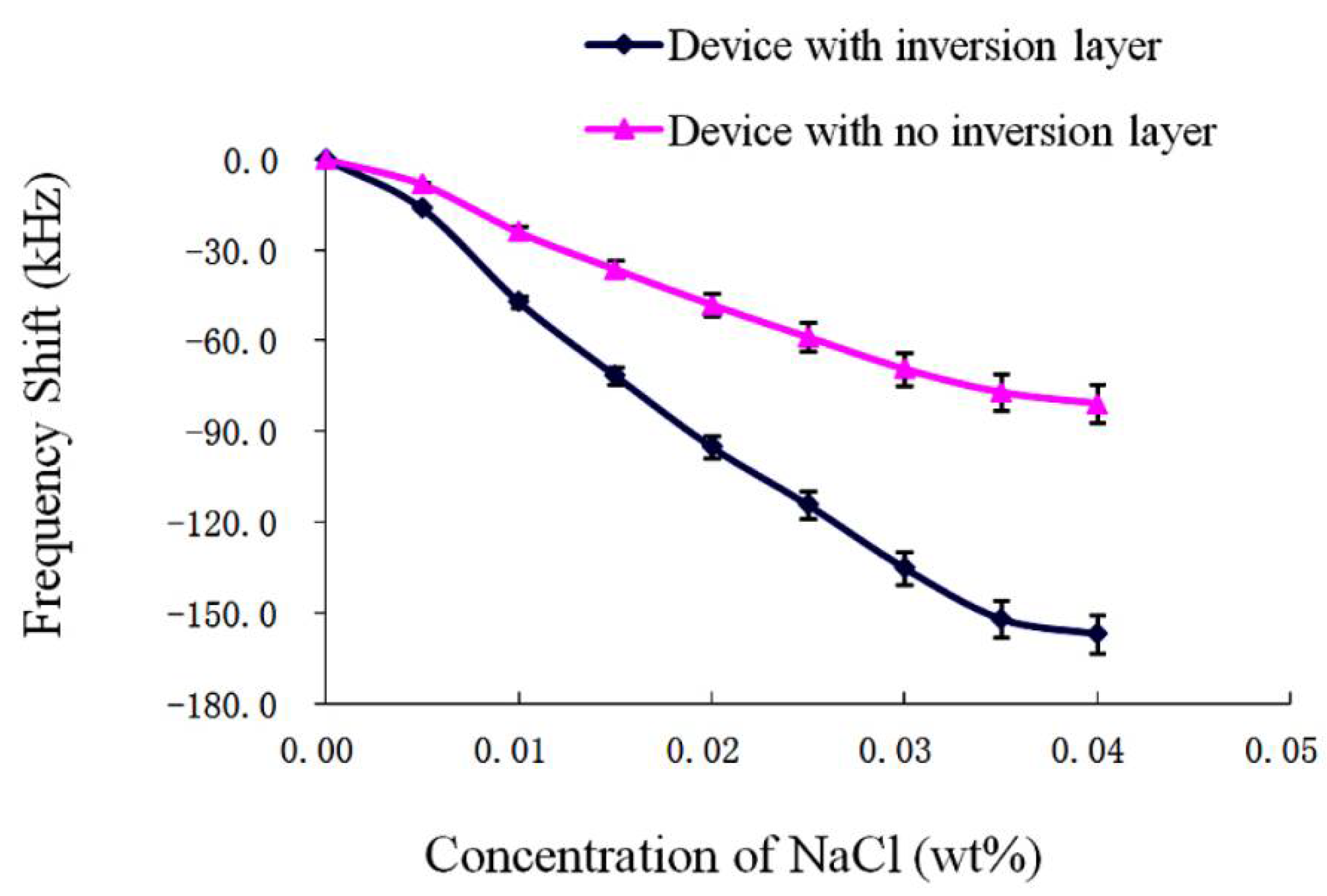
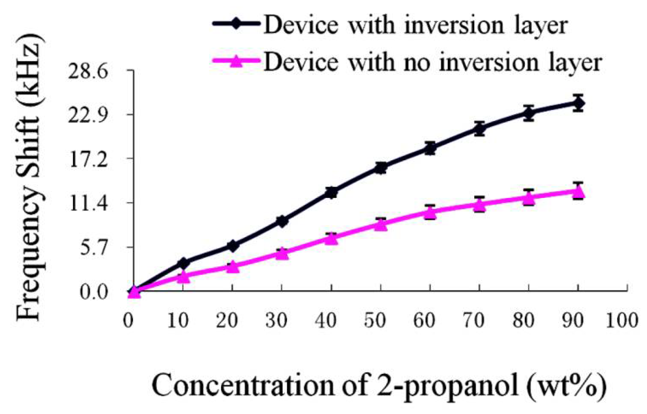
3. Results and Discussion

In this work, the devices with an inversion layer operate in the second harmonic mode, which contributes to the high sensitivity and good frequency stability of the device. Besides, LFE devices with no inversion layer operate in the fundamental resonance frequency.
The sensor was fixed in a fixture, and then connected to a frequency detector, which transmits frequency data to the computer through a serial port. Figure 4 shows the experimental results of the frequency-time curves of the device in 30% isopropanol aqueous solution within 20 min. The average Allan variance and frequency variation range of twenty-five experiments for each kind of device was calculated, and the results are shown in Table 1. The maximum frequency change of the LFE device with no polarity inversion layer process is 9 Hz, and the Allan variance is 4.47. The maximum frequency change of the LFE device with a polarity inversion layer is about 6 Hz, and the Allan variance is 3.28, which is significantly smaller than that of the device with no inversion layer. It can be seen that the LFE devices with a polarity inversion layer can obtain better frequency stability.
The sensitivities of (yxl) 21.82° LiNbO3 LFE devices with and without a polarity inversion layer to the changes of the dielectric constant and the conductance of the liquid were tested. For NaCl aqueous solutions with concentrations of 0~0.04 wt%, the liquid conductivity range of changes is 10~800 × 10−4 s/m. In addition, for isopropanol aqueous solution with concentrations of 0~90 wt%, the relative dielectric constant range of changes is 80~23. The sensitivity results of devices are shown in Figure 5 and Figure 6. As can be seen from Figure 5, the sensitivity of the device with a polarity inversion layer to the conductivity change of liquid is about 2.4 times higher than that of the device with no polarity inversion layer. As can be seen from Figure 6, the sensitivity of the device with a polarity inversion layer to the dielectric constant change of the liquid is about 2.1 times higher than that of the device with no polarity inversion layer.
For piezoelectric bulk acoustic wave devices, in order to increase the resonance frequency, the crystal substrate of the device needs to be thinner, but it will bring inconvenience to the crystal processing. If the device is too thin, it is easy to be broken in the process of use. In addition, the harmonic modes of third or higher degree are difficult to be applied in LFE sensor because of the high resonance impedance. The emergence of the polarity inversion layer technology makes the LFE device work in the second harmonic mode with good resonance characteristics, which improves not only the sensitivities of the device but also the frequency stability of the sensor.

4. Conclusions

In view of the influences of the polarity inversion layer on the performances of the LFE piezoelectric sensor, LFE piezoelectric sensors with a polarity inversion layer were designed and manufactured, and the frequency stabilities and the sensitivities to the change of liquid electrical characteristics of the sensors were further tested. The results show that the resonance frequency stabilities of the LFE device with a polarity inversion layer are obviously better than that of the device with no polarity inversion layer (the Allan variance of the former is about two-thirds of the latter). This is mainly attributed to the fact that the polarity inversion layer structure can suppress parasitic vibration modes, so the device has better frequency stability. In addition, for changes in liquid conductivity and dielectric properties, the sensitivity of the device with a polarity inversion layer is about 2.4 and 2.1 times that of the device with no polarity inversion layer, respectively. The polarity inversion layer of the piezoelectric crystal can significantly improve the sensing performances of the piezoelectric device excited by the lateral electric field, and it can be easily realized by a heat-treatment process. Therefore, the polarity inversion layer technology has a good application prospect in LFE thickness-shear mode acoustic sensors.

Author Contributions

Y.Z. and T.M. presented the idea. F.S. and K.X. accomplished investigation. Discussion about the results and the manuscript writing was contributed to by all authors. All authors have read and agreed to the published version of the manuscript.

Funding

The current study was supported by the National Natural Science Foundation of China (Nos. 11772163), the Natural Science Foundation of Zhejiang Province (Nos. LY21A020007, LY19A020003), Ningbo Municipal Bureau of Science and Technology (Grant No. 2019B10122), and the Public Welfare Foundation of Ningbo City (No. 202002N3118).

Conflicts of Interest

The authors state that there is no conflict of interest.

References

  1. Stevens, D.S.; Tiersten, H.F. An analysis of doubly rotated quartz resonators utilizing essentially thickness modes with transverse variation. J. Acoust. Soc. Am. 1986, 79, 1811–1826. [Google Scholar] [CrossRef]
  2. Qian, Z.H.; Kishimoto, K.; Yang, J.S. Propagation of thickness-twist wave in a piezoelectric ceramic plate in contact with viscous fluids. Acta Mech. 2010, 212, 263–270. [Google Scholar] [CrossRef]
  3. Shi, H.; Yan, L.; Zheng, Y.; Ma, T.; Wang, M.; Huang, B.; Yuan, L.; Wang, J.; Du, J.; Zhang, H. Piezoelectric resonators excited by lateral electric fields based on a LiTaO3 single crystal. Crystals 2020, 10, 525. [Google Scholar] [CrossRef]
  4. Zhang, H.; Gao, Y. Acoustic vortex beam generation by a piezoelectric transducer using spiral electrode. Chin. Phys. Lett. 2019, 36, 114302. [Google Scholar] [CrossRef]
  5. Bi, H.Z.; Zhang, H.; Wang, M.G. Study on thickness mode of piezoelectric ceramic disk with discrete series electrode structure. In Proceedings of the 13th Symposium on Piezoelectrcity, Acoustic Waves and Device Application, Harbin, China, 11–14 January 2019; pp. 1–5. [Google Scholar]
  6. Hu, Y.T.; Yang, J.S.; Zeng, Y.; Jiang, Q.A. High-sensitivity, dual-plate, thickness-shear mode pressure sensor. IEEE Trans. Ultrason. Ferroelectr. Freq. Contr. 2006, 53, 2193–2197. [Google Scholar] [CrossRef]
  7. Latif, U.; Rohrer, A.; Lieberzeit, P.A.; Dickert, F.L. QCM gas phase detection with ceramic materials-VOCs and oil vapors. Anal. Bioanal. Chem. 2011, 400, 2457–2462. [Google Scholar] [CrossRef] [PubMed]
  8. Shen, D.Z.; Zhang, H.T.; Kang, Q.; Zhang, H.J.; Yuan, D.R. Oscillating frequency response of a langasite crystal microbalance in liquid phases. Sens. Actuators B 2006, 119, 99–104. [Google Scholar] [CrossRef]
  9. Yang, J.S. The Mechanics of Piezoelectric Structures; World Scientific: Singapore, 2006. [Google Scholar]
  10. Liu, B.; Jiang, Q.; Hu, Y.T.; Yang, J.S. High-frequency vibrations of piezoelectric plates driven by lateral electric fields. Int. J. Eng. Sci. 2011, 49, 1435–1442. [Google Scholar] [CrossRef]
  11. Hu, Y.H.; French, L.A.; Radecsky, K.; Da Cunha, M.P.; Millard, P.; Vetelino, J.F. A lateral field excited liquid acoustic wave sensor. IEEE Trans. Ultrason. Ferroelectr. Freq. Contr. 2004, 51, 1373–1380. [Google Scholar] [CrossRef] [PubMed]
  12. Hempel, U.; Lucklum, R.; Hauptmann, P.; EerNisse, E.P.; Puccio, D.; Diaz, R.F.; Vives, A.A. Lateral field excited quartz crystal resonator sensors for determination of acoustic and electrical properties of liquids. In Proceedings of the 2008 IEEE International Frequency Control Symposium, Honolulu, HI, USA, 19–21 May 2008; pp. 705–710. [Google Scholar]
  13. Hu, Y.; Pinkham, W.; French, L.A.J.; Frankel, D.; Vetelino, J.F. Pesticide detection using a lateral field excited acoustic wave sensor. Sens. Actuators B 2005, 108, 910–916. [Google Scholar] [CrossRef]
  14. Hempel, U.; Lucklum, R.; Hauptmann, P.R. Lateral field excited acoustic wave devices: A new approach to bio-Interface sensing. In Proceedings of the 2007 IEEE Frequency Control Symposium, Geneva, Switzerland, 29 May–1 June 2007; pp. 426–430. [Google Scholar]
  15. Baron, C.; Cheng, H.; Mool, C.G. Domain inversion in LiTaO3 and LiNbO3 by electric field application on chemically patterned crystals. App. Phys. Lett. 1996, 68, 481–483. [Google Scholar] [CrossRef]
  16. Zhou, Q.F.; Cannata, J.M.; Shung, K.K. Design and modeling of inversion layer ultrasonic transducers using LiNbO3 single crystal. Ultrasonics 2006, 44, e607–e611. [Google Scholar] [CrossRef] [PubMed]
  17. Nakamura, K.; Fukazawa, K.; Yamada, K. Broadband ultrasonic transducers using a LiNbO3 plate with a ferroelectric inversion layer. IEEE Trans. Ultrason. Ferroelectr. Freq. Contr. 2003, 50, 1558–1562. [Google Scholar] [CrossRef] [PubMed]
  18. Ma, T.F.; Wang, J.; Du, J.K.; Yuan, L.L.; Zhang, Z.T.; Zhang, C. Effect of the ferroelectric inversion layer on resonance modes of LiNbO3 thickness-shear mode resonators. Appl. Phys. Express 2012, 5, 116501. [Google Scholar] [CrossRef]
  19. Ma, T.F.; Wang, J.; Du, J.K.; Yang, J.S. Lateral-Field-Excited electromechanical resonances in a LiNbO3 crystal plate with a ferroelectric inversion layer. Ferroelectrics 2015, 486, 184–192. [Google Scholar] [CrossRef]
  20. Zhang, C.; Vetelino, J.F. Bulk acoustic wave sensors for sensing measurand induced electrical property changes in solutions. IEEE Trans. Ultrason. Ferroelectr. Freq. Contr. 2001, 48, 773–778. [Google Scholar] [CrossRef] [PubMed]
  21. French, L.A.; McCann, D.F.; Wark, M.; Winters, S.; Vetelino, J.F. A Lateral Field Excited Acoustic Wave Sensor. In Proceedings of the International Solid-State Sensors, Actuators and Microsystems Conference, Lyon, France, 10–14 June 2007; pp. 1287–1290. [Google Scholar]
Figure 1. Schematic diagram of a lithium niobate crystal plate with a polarity inversion layer.
Crystals 11 00407 g001
Figure 2. An LFE sensor based on a lithium niobate crystal plate.
Crystals 11 00407 g002
Figure 3. Experimental platform.
Crystals 11 00407 g003
Figure 4. Frequency-time curves of LFE sensors in 30% isopropanol aqueous solution within 20 min: (a) device with no inversion layer, (b) device with an inversion layer.
Crystals 11 00407 g004
Figure 5. Frequency shifts of the LFE devices to the conductivity change of liquid.
Crystals 11 00407 g005
Figure 6. Frequency shifts of the LFE devices to the dielectric characteristic change of liquid.
Crystals 11 00407 g006
Table 1. The average Allan variances and frequency variation ranges.
Device TypeFrequency Variation Range (Hz)Allan Variance
With no inversion layer±94.47
With an inversion layer±63.28
Publisher’s Note: MDPI stays neutral with regard to jurisdictional claims in published maps and institutional affiliations.

