Abstract
The synthesis of Mg-Al layered double hydroxide (LDH) was explored, through a one-step wet mechanochemical route, with the use of a NETZSCH LME 1 horizontal bead mill. Raw materials selected comprised of a mixture of metallic oxides/hydroxides promoting green synthesis. The research aims to expand on the understanding of the wet mechanochemical synthesis of Mg-Al LDH through variation in milling and synthesis parameters. The selected parameters investigated were rotational speed, retention time, solids loading, bead size and jacket water inlet temperature. Samples were collected, filtered and dried at 60 °C for 12 h. Unless stated otherwise, or under investigation, parameters were kept constant at pre-selected conditions adapted from existing literature. LDH synthesis was deemed to occur successfully at elevated jacket water temperatures of 50 °C and longer retention times. It was noted that Al(OH)3 XRD peak reduction occurred readily for increased rotational speeds and residence times, regardless of system temperature. MgO was deemed to react more readily at elevated temperatures. It was proposed that the amorphitisation and mechanochemical activation of Al(OH)3 contributed to its dissolution providing the relevant Al3+ ions necessary for Mg2+ isomorphic substitution. Increasing the system temperature promoted the hydration of MgO, with the absence of Mg(OH)2 attributed to its contribution as an intermediate phase prior to LDH formation.
1. Introduction
Layered double hydroxides (LDHs) are clay-like minerals, commonly referred to as ‘anionic clays’, represented by the general formula [MII1−x MIIIx(OH)2][Xq−x/q·H2O]. The selected divalent and trivalent metal elements are represented by MII and MIII and the interlayer composition is denoted by [Xq−x/q·H2O]. Common applications for LDH materials include pharmaceuticals, as additives in cosmetics and polymers, as nanomaterial’s and within the field of catalysis. This is primarily due to their wide variety of physical and chemical properties, such as having variable charge density, a reactive interlayer space, ion exchange capabilities, varying chemical compositions and rheological properties [1].
Multiple techniques exist for the synthesis of LDH materials. These traditionally include co-precipitation, reconstruction, the urea method, induced hydrolysis, sol-gel and hydrothermal methods [1,2]. Many existing synthesis techniques produce environmentally unfriendly effluents or by-products, are energy intensive, make use of metallic salts or require complex inert environments which are difficult to scale to a commercial level [3]. The need for ‘green’ synthesis methods are therefore often sought after.
The use of mechanochemistry as an alternative technique has gained wide-spread attention. Mechanochemical processes can induce chemical reaction and structural changes through the use of a mechanical force. Solid-state reactions result in the formation of a product phase that is separate to that of selected reactant phases. The formation of meta-stable structures through milling can overcome reaction diffusion limitations and eliminate the need for high reaction temperatures. Additionally, mechanical processing can contribute to extended solid solubility, amorphitisation and disordering [4]. Multiple mechanochemical techniques have been explored [3] with the promise of producing LDHs with unique elemental and structural combinations [5,6]. Traditional mechanochemical techniques involved in the synthesis of LDH materials include single-step or one-pot grinding [7,8], mechano-hydrothermal synthesis [9,10,11,12] and two-step grinding. Two-step grinding can include an initial grinding step followed by either an additional treatment step or a second grinding step [13,14,15]. The milling of raw materials or reaction products can be conducted wet, dry or as a paste. A review paper by [3] has indicated that a wide variety of techniques and combinations involving wet and dry grinding have previously been investigated and proven promising.
Wet grinding is a process in which solid particles are suspended within a liquid medium and is commonly referred to as slurry milling. This process of milling offers several advantages over dry milling such as thermal control, operational safety and reduced environmental impact. Dry milling processes often result in the production of fines or small particles that may be hazardous to the environment. Thermal control can be achieved either through the selected medium or with the use of a water jacket. This prevents chemical decomposition, solid phase transitions or melting of selected materials [16]. Single step wet grinding has previously been considered unsuitable for solid state chemistry as the addition of water to the system may reduce the degree of amorphitisation and prevent active site formation [17]. Dry grinding methods are therefore typically conducted prior to wet grinding or any other additional synthesis step, as the absence of water allows for sufficient active site formation and amorphitisation. Dry grinding has successfully incorporated multiple different secondary synthesis steps in the formation of LDH. These methods have included dry grinding of raw materials followed by agitating the material in a solution of the selected anion for intercalation [18,19,20,21]. Additionally, LDH synthesis methods have involved dry grinding followed by washing or thermal treatment [3,22], wet grinding [17,23] or methods making use of ultrasonic irradiation [24,25,26]. Limited research has been conducted on single step wet grinding and low conversion rates obtained warrant the need for further research [3,27,28]. Incomplete conversion or little to no LDH formation has previously been attributed to the quantity of water present, with insufficient mechanical activation of raw materials occurring [17].
A recent study attempted to expand on the wet mechanochemical synthesis of Ca-Al, Mg-Al, Zn-Al and Cu-Al LDH materials by making use of a NETZSCH LME 1 horizontal bead mill [28]. The synthesis method included a wet grinding step followed by an additional ageing step at 80 °C for 24 h. LDH synthesis was deemed to be successful with conversion observed to be incomplete. This study serves as a continuation of previous work [28] by expanding on the one-step wet mechanochemical synthesis of Mg-Al LDH, using a NETZSCH LME 1 horizontal bead mill, through varying milling and synthesis parameters. Raw materials selected were a combination of commercial grade hydroxides and oxides, promoting green synthesis and providing insight on commercial viability. The use of oxides/hydroxides eliminate additional processes required to treat environmentally harmful, salt-containing effluents produced from traditional LDH synthesis techniques [29]. The selected mill is designed specifically for wet grinding application, including homogenisation of selected solids in the liquid medium, deagglomeration, dispersion and wetting of solids [30]. The mill further has potential for industrial application as a result of high volumes and a wide speed spectrum, allowing for effective comminution [30]. Traditional mechanochemical techniques associated with LDH synthesis often make use of ball mills, mixer mills or a mortar and pestle [3]. The study further aimed to provide insight on the effects of mechanochemical activation and amorphitisation of poorly soluble oxides and hydroxides, such that LDH formation occurred. Additionally, the ageing step was removed to determine if changes in milling parameters could provide potential for a one-step process. The selected parameters investigated were rotational speed, residence time, solids loading, bead size and jacket water temperature.
2. Materials and Methods
2.1. Milling Operation and Experimental Conditions
The influence of milling parameters on the synthesis of Mg-Al LDH was investigated by making use of a NETZSCH LME 1 horizontal bead mill. Selected raw materials were wet batch milled under air atmosphere. Batch set-up was as described and illustrated by [28]. Starting materials selected were commercial grade MgO (86% Chamotte Holdings) and Al(OH)3 (99.2% Belguam Indal), at a set M2+:M3 ratio of 2:1, facilitating the synthesis of Mg4Al2(OH)14·nH2O. MgO was selected to increase system pH such that Al(OH)3 dissolution was encouraged, and was calcined at 800 °C for 1 h to remove any carbonates or hydroxide phases. Prior to each experimental run the milling chamber was loaded to a volumetric capacity of 60% (0.735 L) with an outer jacket water flowrate of 525 L·h−1. Water of the correct stoichiometric amount was initially added to the system, through the bead filling connection, such that the selected solids loading would be correct. The dry oxide/hydroxide powders were then mixed in a beaker and slowly funnelled into the system. The bead filling connection was sealed and the experimental run would commence. Water was not boiled prior to each experimental run and all runs were conducted without the addition of an inert gas. LDH synthesised was therefore expected to contain some carbonate within the interlayer despite no direct carbonate source. Milling media selected were spherical and comprised of yttrium stabilised zirconia due to its highly inert nature. All samples were collected, gravity filtered and dried at 60 °C for 12 h under atmospheric conditions. Parameters listed above were kept constant throughout each experimental run conducted.
The selected milling parameters investigated were rotational speed, retention time, solids loading, bead size and jacket water inlet temperature. Unless stated otherwise or specifically under investigation, each of these parameters were kept constant, for each of the experimental runs conducted, at the following conditions:
- Rotational speed: 2000 rpm;
- Retention time: 1 h;
- Solids loading: 10%;
- Milling media bead size: 2 mm;
- Jacket water inlet temperature: 30 °C.
The influence of milling parameters were investigated as follows:
- The rotational speed was varied at 1000 rpm, 2000 rpm and 3000 rpm;
- The retention time was varied at 1 h, 2 h and 3 h;
- The Solids loading was varied at 10%, 20% and 30%;
- Milling media size was varied from 2 mm to a size of 0.25 mm;
- The jacket water inlet temperature was increased from 30 °C to 50 °C. The increase in temperature was investigated for a change in rotational speed at 1000 rpm, 2000 rpm and 3000 rpm. Similarly, the change in temperature was further investigated with a change in retention time for 1 h, 2h and 3 h, at a rotational speed of 2000 rpm.
A summary of the selected experimental conditions for each of the samples collected is depicted in Table 1.

Table 1.
Selected milling and synthesis parameters for each sample collected.
2.2. Material Characterisation
2.2.1. X-ray Fluorescence (XRF)
All samples were dried at 100 °C and roasted at 1000 °C to determine the mass loss upon ignition. Additionally, 1 g of sample was mixed with 6 g of Lithium tetraborate flux and fused at 1050 °C to form a stable glass bead. Analysis was conducted with the use of a Thermo Fischer ARL Perform ‘X Sequential instrument (Thermo Fischer, MA, USA). Samples were further characterised using UNIQUANT software.
2.2.2. Particle Size Analysis (PSA)
Collected samples were analysed wet, to ensure full dispersion, by making use of a Mastersizer 3000 (Malvern Panalytical, Malvern, UK) with a Hydro LV liquid unit. Samples were collected periodically to observe a change in particle size with time.
2.2.3. X-ray Diffraction Analysis (XRD)
Powdered samples were analysed using a PANalytical X’Pert Pro powder diffractometer in - configuration, fitted with an X’Celerator detector and variable divergence- and fixed receiving slits (Malvern Panalytical, Malvern, UK). The set-up made use of a Fe filtered Co-K ( = 1.789 Å) source. Sample preparation was conducted with the use of a standardised PANalytical backloading system which provides a random particle distribution. Samples were scanned from 5° to 90° with a step size of 0.008°. Mineralogy of samples were determined using the ICSD database in correlation with X’Pert Highscore plus software.
2.2.4. Fourier Transform Infrared Spectroscopy (FT-IR)
FT-IR spectra for dry samples were obtained with the use of a PerkinElmer 100 Spectrophotometer (PerkinElmer, MA, USA) over a range of 550–4000 cm−1. Samples were analysed with an average of 32 scans at a resolution of 2 cm−1.
2.2.5. Scanning Electron Microscopy (SEM)
Sample morphology was investigated by making use of a Zeiss Gemini 1 cross beam 540 FEG SEM (Oberkochen, Germany). Dry, powdered samples were secured onto an aluminium sample holder and coated with graphite 5 times using a Polaron Equipment E5400 SEM auto-coating sputter system (Quorum, East Susex, UK).
3. Results
3.1. X-ray Fluorescence (XRF)
XRF analysis was conducted to ensure the correct M2+:M3+ ratio was added to the system, as well as observe the effects on mill and milling media degradation. Table 2 summarises the the calculated M2+:M3+ ratios for each sample as calculated from XRF data obtained. Contaminants such as Fe2O3, ZrO2 and Y2O3 were noted to be present. The presence of Fe2O3 indicates milling chamber degradation, whereas ZrO2 and Y2O3 are the result of media degradation. The exact elemental composition of the LDH formed within each system could not be determined due to incomplete conversion and the amorphous nature of the samples. It should be further noted that SiO2 was present as a commercial impurity in the raw MgO selected.
Table 2.
M2+:M3+ ratios for each sample as calculated from XRF data obtained.
3.2. Particle Size Analysis (PSA)
Unless stated otherwise, particle size analysis was conducted wet and at the end of each experimental run. Table 3 summarises the particle size measurements obtained for each sample.
Table 3.
Particle size analysis for a change in milling and synthesis parameters.
3.2.1. Rotational Speed and Jacket Water Inlet Temperature
Particle size measurements for samples S1, S2 and S3 were observed to fluctuate with no clear trend identifiable. The particle size distribution (PSD) for each sample is depicted in Figure 1 and Figure 2. The distribution for S1 exhibits a bi-modal distribution with a minor peak or agglomeration tail at particle sizes between 10 m and 100 m. The addition of contaminants to the system could directly influence particle size measurements obtained and therefore further contribute to discrepancies observed. Sample discolouration was noted with an increase in rotational speed, from a light grey to a dark metallic grey. This indicates an increase in the concentration of contaminants within each sample. Little difference was observed for D10 and D50 measurements obtained for samples S13, S14 and S15. This was further true for D90 measurements obtained for S14 and S15. Comparatively, the D90 for S13 was observably greater than those of S14 and S15. This could be the result of agglomeration, rather than mill or media degradation, as can be seen by agglomeration tail depicted in Figure 2.
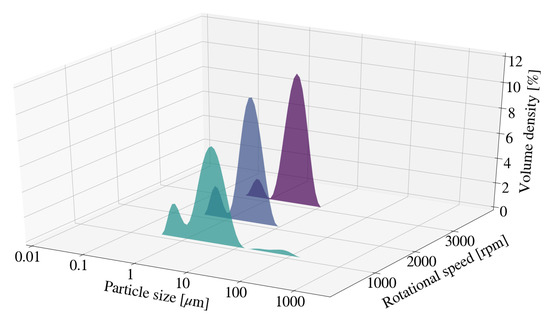
Figure 1.
Particle size distribution for Mg-Al LDH samples synthesised at a cooling water inlet temperature of 30 °C, with a change in rotational speed (S1, S2, S3).
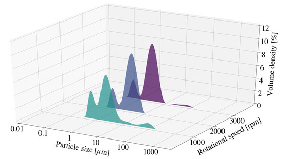
Figure 2.
Particle size distribution for Mg-Al LDH samples synthesised at a cooling water inlet temperature of 50 °C, with a change in rotational speed (S13, S14, S15).
3.2.2. Residence Time and Jacket Water Inlet Temperature
Particle size was measured periodically for a change in retention time for sample S6 and S12. Figure 3, Figure 4 and Figure 5 depict the change in particle size with time, as well as the respective milling curves, obtained for 3 hours of milling activity. The D90, D50 and D10 measurements for S6, prior to milling, were 17.20 m, 7.10 m and 1.96 m respectively. The PSD changed from a primarily uni-modal distribution to a clear bi-modal distribution after 10 min of milling. The distribution seemingly plateaued after approximately 60 min, coinciding with particle size measurements depicted in Figure 3. Bi-modal distributions result when two distinct particle size populations exist. It is unclear if either the PSD or the measured particle sizes would have continued to decrease with time, or whether the bi-modal distribution would result in an eventual uni-modal distribution. The formation of chemical species or amorphous precursors could contribute to observed phenomenon. The respective D90, D50 and D10 measurements obtained for the S12 raw material mixture, prior to milling were 17.3 m, 6.89 m and 1.89 m. The D10 and D50 particle sizes measurements for S12 were noted to be smaller than that of S6. The PSD for S12 shifted to form a clear bi-modal distribution. The mode located between 1 m and 10 m was noted to decrease in size and shift, forming a dominant mode between 0.1 m and 1 m. The shift in bi-modal distribution could be the result of formation fine platelets and LDH as supported by XRD patterns obtained in Section 3.3.2.
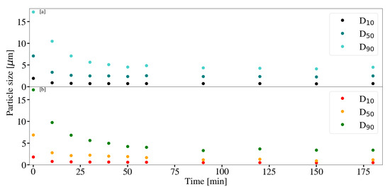
Figure 3.
(a) Particle size measurements with time for Mg-Al LDH samples synthesised at a cooling water inlet temperature of 30 °C, with a change in retention time (S6). (b) Particle size measurements with time for Mg-Al LDH samples synthesised at a cooling water inlet temperature of 50 °C, with a change in retention time (S12). Milling parameters were set at a rotational speed of 2000 rpm, media size of 2 mm and a solids loading of 10%.
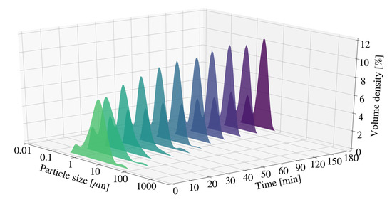
Figure 4.
Particle size distribution for Mg-Al LDH samples synthesised at a cooling water inlet temperature of 30 °C, with a change in residence time (S6).
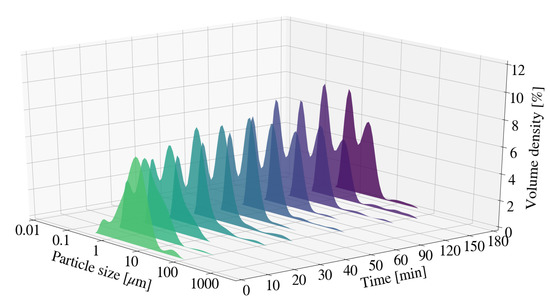
Figure 5.
Particle size distribution for Mg-Al LDH samples synthesised at a cooling water inlet temperature of 50 °C, with a change in residence time (S12).
3.2.3. Solids Loading
Samples S7 and S8 depicted no clear trend for particle size measurements at the end of each experimental run. It was noted that both S7 and S8 resulted in greater particle size measurements than S2 and was likely due to agglomeration. This is supported by the presence of small modes located between 10 m and 100 m for the relevant distributions depicted in Figure 6. The PSD for all samples depicted a multi-modal distribution, with the dominant mode located between 1 m and 10 m. As described in Section 3.2.2 the multi-modal distribution could be the result of fine platelets or minor quantities of new chemical species.
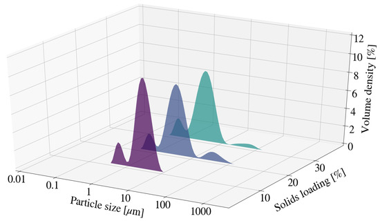
Figure 6.
Particle size distribution for Mg-Al LDH samples synthesised at a cooling water inlet temperature of 30 °C, with a change in solids loading (S2, S7, S8).
3.2.4. Bead Size
In Figure 7, the overall particle size measurements for S9 were noted to be lower than that of S2. The reduction in size from 2 mm to 0.25 mm results in an increase in the quantity of milling beads and therefore a substantial increase in the number of stress events within a set volume [30]. It was worth noting that the particle size for S6 after 60 min exhibited D10, D50 and D90 measurements of 0.725 m, 2.55 m, and 4.85 m respectively. The measurements were similar to those of S9. Additionally, XRD patterns in Section 3.3.4 indicate that LDH formation occurred. The effect associated with a change in media size on the final particle size of the sample was therefore unclear.
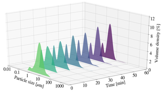
Figure 7.
Particle size distribution for Mg-Al LDH samples synthesised at a cooling water inlet temperature of 50 °C, with a change in media size (S9).
3.3. X-ray Diffraction Analysis (XRD)
3.3.1. Rotational Speed and Jacket Water Inlet Temperature
Figure 8 depicts the XRD pattern for S1, S2 and S3. No clear LDH peaks were observed for samples obtained. Amorphous LDH precursor or mixed-metal hydroxides could be present within the sample, however was not identifiable through XRD data obtained. SiO2 was present as an inert impurity in all samples obtained and could be a qualitative indication of the degree of amorphitisation within a sample. The peak intensity for SiO2 decreased with an increase in the rotational speed. Unique to the type of mill used, a critical rotational speed exists at which the media is pinned to the chamber walls. This prevents grinding of the powders from occurring [31]. The decrease in SiO2 peaks indicate that grinding does still occur for the maximum selected speed of 3000 rpm. Higher operational speeds influence the kinetic energy related to the media, as well as the sample particles, and therefore increase the milling intensity. This would result in an increase in the quantity of particle-particle and particle-media collisions within a specified time frame [31]. Peak reduction was further observed to occur for Al(OH)3 and MgO. The degree of peak reduction for Al(OH)3 was notably greater than that of MgO. It was further noted that no Mg(OH)2 was present within samples obtained.
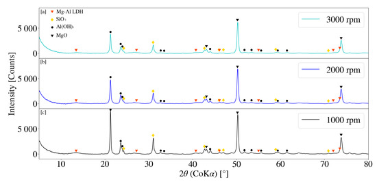
Figure 8.
(a) X-ray diffraction pattern for Mg-Al LDH sample synthesised at a rotational speed of 3000 rpm (S3). (b) X-ray diffraction pattern for Mg-Al LDH sample synthesised at a rotational speed of 2000 rpm (S2). (c) X-ray diffraction pattern for Mg-Al LDH sample synthesised at a rotational speed of 1000 rpm (S1). Milling parameters were set at a retention time of 1 h, jacket water inlet temperature of 30 °C, media size of 2 mm and a solids loading of 10%.
The XRD pattern for samples S13, S14 and S15 is depicted in Figure 9. MgO and Al(OH)3 peaks decreased with an increase in operating speed. Comparatively, the decrease in raw material peaks for samples S1,S2 and S3 exhibited similar behaviour and intensities. It was noted that Al(OH)3 peaks reduced more readily than that of MgO regardless of the selected jacket water inlet temperature and could be the result of amorphitisation. The formation of minor broad peaks, likely that of LDH, were observed to form for samples exposed to higher jacket water temperatures. Samples synthesised at lower temperatures exhibited little to no obvious peak formation. Temperature effects on the synthesis of LDH materials are considered to be complex. Agitation of milled samples at elevated temperatures have resulted in both an increase in crystallinity and conversion of raw materials to LDH product [28]. It could be possible that samples exposed 50 °C temperatures exhibit an increase in conversion of raw materials to LDH product as well as improvements on the crystallinity. A residence time of 1 h was insufficient to determine the relevant effects.
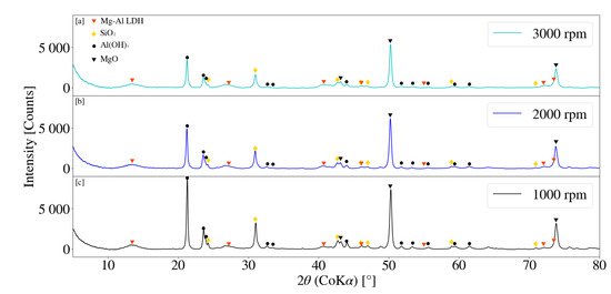
Figure 9.
(a) X-ray diffraction pattern for Mg-Al LDH sample synthesised for a rotational speed of 3000 rpm (S15). (b) X-ray diffraction pattern for Mg-Al LDH sample synthesised for a rotational speed of 2000 rpm (S14). (c) X-ray diffraction pattern for Mg-Al LDH sample synthesised for a rotational speed of 1000 rpm (S13). Milling parameters were set at a residence time of 1 h, jacket water inlet temperature of 50 °C, media size of 2 mm and a solids loading of 10%.
3.3.2. Residence Time and Jacket Water Inlet Temperature
XRD patterns for samples S4, S5 and S6 are depicted in Figure 10. LDH could be construed as being present for samples S4 and S5 with minor, broad primary peaks at 2 values of 13.50° and 13.54°. LDH XRD patterns were however not clearly identifiable. Peak intensity for Al(OH)3 and MgO were observed to decrease with an increase in residence time, with Al(OH)3 peak reduction observably greater than that of MgO. It was further noted that the SiO2 peaks exhibited a decreasing trend with an increasing retention time. An increase in residence time results in the decrease of the average particle size, as could be seen in Section 3.2.2 [31]. A decrease in the particle size of a solid results in an increase in the exposed surface area, affecting dissolution performance [16]. Peak reduction and broadening could therefore result from factors such as amorphitisation, particle size reduction, dissolution and formation of chemical species.
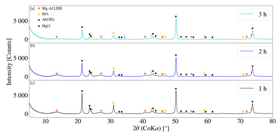
Figure 10.
(a) X-ray diffraction pattern for Mg-Al LDH sample synthesised for a residence time of 3 h (S6). (b) X-ray diffraction pattern for Mg-Al LDH sample synthesised for a residence time of 2 h (S5). (c) X-ray diffraction pattern for Mg-Al LDH sample synthesised for a residence time of 1 h (S4). Milling parameters were set at a rotational speed of 2000 rpm, jacket water inlet temperature of 30 °C, media size of 2 mm and a solids loading of 10%.
Figure 11 depicts the XRD patterns obtained for samples S10, S11 and S12 for a change in residence time at a jacket water inlet temperature of 50 °C. Broad LDH peaks were observed for each sample obtained, with S12 yielding the best result. Primary and secondary peaks for S12 were located at approximate 2 measurements of 13.73° and 26.90° respectively. Similarly S10 and S11 exhibited primary LDH peaks at 2 values of 13.58° and 13.62°, with secondary peaks located at 26.83° and 26.93° respectively. LDH peak intensities gradually increased with an increase in residence time from 1 h to 3 h. Comparatively a clear decreasing trend was observed for MgO and Al(OH)3 peak intensities. It was noted that the MgO peaks reduced more readily than those for samples synthesised at 30 °C. LDH patterns obtained were observed to be more prominent than that obtained for S4, S5 and S6 at a jacket water inlet temperature of 30 °C. Reaction temperatures influence the chemical kinetics and reaction rate of a system [32]. Similarly, in combination with particle size reduction, temperature was also expected to affect the dissolution properties of the chemical species involved [16]. LDH XRD patterns obtained were observed to exhibit similar characteristics to those previously reported in literature [17,28,33].
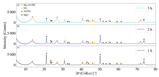
Figure 11.
(a) X-ray diffraction pattern for Mg-Al LDH sample synthesised for a residence time of 3 h (S12). (b) X-ray diffraction pattern for Mg-Al LDH sample synthesised for a residence time of 2 h (S11). (c) X-ray diffraction pattern for Mg-Al LDH sample synthesised for a residence time of 1 h (S10). Milling parameters were set at a rotational speed of 2000 rpm, jacket water inlet temperature of 50 °C, media size of 2 mm and a solids loading of 10%.
3.3.3. Solids Loading
Figure 12 depicts the XRD patterns for samples S2, S7 and S8 for a change in solids loading. Minor primary LDH peaks were observed to be present for solid loading’s of 20% and 30%, at 2 values of 13.40° and 13.38° respectively. No obvious LDH pattern was observed for S2 at a solids loading of 10% and no clear trend identifiable. The number of collisions, as well as the force associated with each, is directly influenced by the density of solids within a mill [16]. It was noted that the reduction in SiO2 peaks were greatest for S2 with little difference observed between that of S7 and S8. Sample viscosity observably increased with an increase in solids loading. Similarly, MgO and Al(OH)3 peak reduction was greatest for the lowest selected solids loading (S2). It is possible that the grinding activity became restricted as media movement decreased with an increase in the selected loading’s [31] and the subsequent viscosity of the slurry.
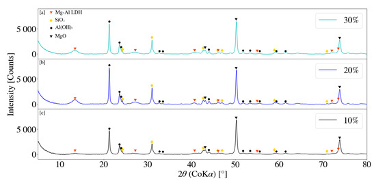
Figure 12.
(a) X-ray diffraction pattern for Mg-Al LDH sample synthesised with a 30% solids loading (S8). (b) X-ray diffraction pattern for Mg-Al LDH sample synthesised with a 20% solids loading (S7). (c) X-ray diffraction pattern for Mg-Al LDH sample synthesised with a 10% solids loading (S2). Milling parameters were set at a rotational speed of 2000 rpm, media size of 2 mm, jacket water inlet temperature of 30 °C and a retention time of 1 h.
3.3.4. Bead Size
XRD patterns for S2 and S9 are depicted in Figure 13. A more prominent, but minor, primary LDH peak was observed at a 2 of 13.51° for S9. The peak intensities for MgO and Al(OH)3 were noted to be lower for S9 when compared to that of S2. This was further observed to be true for peak intensities associated with SiO2. The volume of the bead loading was kept constant at approximately 60% with a measured mass of 2.57 kg and 2.52 kg for the 2 mm and 0.25 mm beads respectively. As stated in Section 3.2.4, for a constant media mass, the overall number of stress events were expected to increase with a decrease in media size [30,32]. An increase in the reactive surface area could therefore have prompted the formation of LDH.
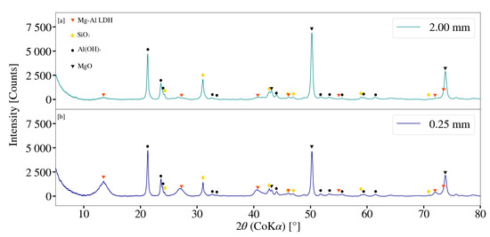
Figure 13.
(a) X-ray diffraction pattern for Mg-Al LDH sample synthesised using milling media size of 2 mm (S2). (b) X-ray diffraction pattern for Mg-Al LDH sample synthesised using milling media size of 0.25 mm (S9). Milling parameters were set at a rotational speed of 2000 rpm, jacket water inlet temperature of 30 °C, retention time of 1 h and a solids loading of 10%.
3.4. Fourier Transform Infrared Spectroscopy (FT-IR)
3.4.1. Rotational Speed and Jacket Water Inlet Temperature
FT-IR analysis for samples synthesised with a change in rotational speed are depicted in Figure 14 and Figure 15. Minor differences were observed between S1, S2 and S3. Peaks located between 3300 cm−1 and 3700 cm−1 could be attributed to the stretching vibrations of free -OH groups, as well as bonded -OH within the sample [17]. The stretching of -OH was likely due to the presence of Al(OH)3 [34]. Peaks observed at approximately 1366 cm−1 indicate CO32− v3 vibrations [17,28,33]. Carbonate contamination was likely due to atmosphere, as samples were synthesised, filtered and dried without the use of an inert environment. Peaks located between 1100 cm−1 and 900 cm−1 are likely the result of Si-O interactions [28,35]. This interaction was present for all samples collected throughout this study. Peaks located between 500 cm−1 and 900 cm−1 could be attributed to M-O and M-OH (M = Mg, Al) vibrations [35]. Samples synthesised at elevated jacket water temperatures exhibited similar data to those synthesised at lower temperatures. It was noted that peaks located between 500 cm−1 and 900 cm−1 exhibited minor changes with a change in rotational speed, as well as a change in the system temperature. This could be the result of changes associated with contaminant concentration. Peak formation at 1366 cm−1 was more prominent at elevated jacket water temperatures. XRD data depicted in Figure 9 exhibited minor, broad peaks that are likely associated with LDH. It is possible that the formation of the more prominent peaks are the result of carbonate within the interlayer of the LDH structure. Peaks located between 3300 cm−1 and 3700 cm−1 exhibited slight broadening with an increase in rotational speed for S13, S14 and S15. This could be due to the -OH stretching vibrations located within the layered structure of the LDH, as well as water molecules within the interlayer [11,17,22,28].
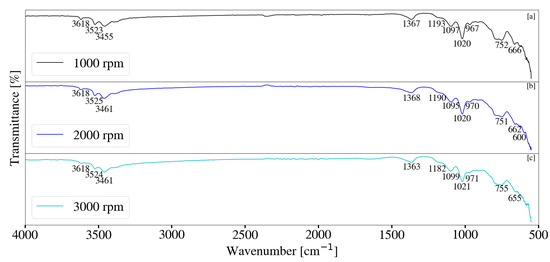
Figure 14.
(a) FT-IR analysis for Mg-Al LDH sample synthesised at a rotational speed of 1000 rpm (S1). (b) FT-IR analysis for Mg-Al LDH sample synthesised at a rotational speed of 2000 rpm (S2). (c) FT-IR analysis for Mg-Al LDH sample synthesised at a rotational speed of 3000 rpm (S3). Milling parameters were set at a retention time of 1 h, jacket water inlet temperature of 30 °C, media size of 2 mm and a solids loading of 10%.
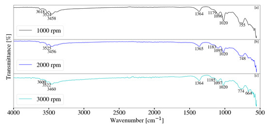
Figure 15.
(a) FT-IR analysis for Mg-Al LDH sample synthesised at a rotational speed of 1000 rpm (S13). (b) FT-IR analysis for Mg-Al LDH sample synthesised at a rotational speed of 2000 rpm (S14). (c) FT-IR analysis for Mg-Al LDH sample synthesised at a rotational speed of 3000 rpm (S15). Milling parameters were set at a retention time of 1 h, jacket water inlet temperature of 50 °C, media size of 2 mm and a solids loading of 10%.
3.4.2. Residence Time and Jacket Water Inlet Temperature
FT-IR analysis for samples synthesised with a change in retention time and jacket water inlet temperature are depicted in Figure 16 and Figure 17. Little difference was observed between samples S4, S5 and S6. Peaks located between 500 cm−1 and 900 cm−1 were observed to change with a change in retention time and are attributed to the M-O and M-OH vibrations [35] within the sample. Changes are likely the result of metallic contaminants as could be seen by XRF data and increased sample discolouration. Samples exhibited peaks between 3300 cm−1 and 3700 cm−1 and correlates to the stretching vibrations of free and bonded -OH within the system [17,36]. The presence of Al(OH)3 was likely the result of the stretching -OH vibrations between 3300 cm−1 and 3700 cm−1 [34]. Minor peaks were present at approximately 1366 cm−1 for low jacket water temperatures and are likely associated with CO32− v3 vibrations [17,33]. These peaks were observed to intensify at elevated temperatures with an increase in residence time. Similarly, peaks located between 3300 cm−1 and 3700 cm−1 broadened, a possible indication of the -OH stretching vibrations and H2O molecules located within the layered LDH structure [11,17,22,28]. This correlates to XRD patterns depicted in Figure 11. FT-IR data associated S10, S11 and S12 were similar to that of Mg-Al LDH reported in literature [11,17,22,28,33].
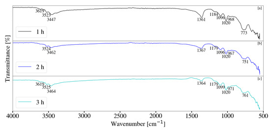
Figure 16.
(a) FT-IR analysis for Mg-Al LDH sample synthesised for a residence time of 1 h (S4). (b) FT-IR analysis for Mg-Al LDH sample synthesised for a residence time of 2 h (S5). (c) FT-IR analysis for Mg-Al LDH sample synthesised for a residence time of 3 h (S6). Milling parameters were set at a rotational speed of 2000 rpm, jacket water inlet temperature of 30 °C, media size of 2 mm and a solids loading of 10%.
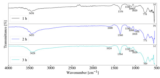
Figure 17.
(a) FT-IR analysis for Mg-Al LDH sample synthesised for a residence time of 1 h (S10). (b) FT-IR analysis for Mg-Al LDH sample synthesised for a residence time of 2 h (S11). (c) FT-IR analysis for Mg-Al LDH sample synthesised for a residence time of 3 h (S12). Milling parameters were set at a rotational speed of 2000 rpm, jacket water inlet temperature of 50 °C, media size of 2 mm and a solids loading of 10%.
3.4.3. Solids Loading
FT-IR analysis for Mg-Al samples synthesised with a change in solids loading is depicted in Figure 18. Despite the presence of small quantities of LDH, as seen by XRD data in Figure 12 samples exhibited minor differences in the FT-IR data obtained. As with other samples, peaks located between 3300 cm−1 and 3700 cm−1 can be assigned to the free and bonded -OH groups within the sample. The presence of Al(OH)3 was once again noted and likely contributed to the stretching -OH vibrations located between 3300 cm−1 and 3700 cm−1. Carbonate contamination was once again observed with peaks located at 1366 cm−1 [17,33]. Differences were noted between 500 cm−1 and 900 cm−1 and could be the result of degradation contamination. Degradation likely decreased with an increase in sample viscosity.
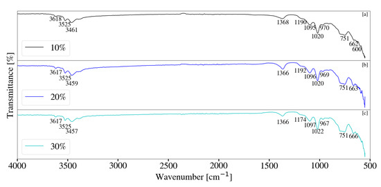
Figure 18.
(a) FT-IR analysis for Mg-Al LDH sample synthesised with a 10% solids loading (S2). (b) FT-IR analysis for Mg-Al LDH sample synthesised with a 20% solids loading (S7). (c) FT-IR analysis for Mg-Al LDH sample synthesised with a 30% solids loading (S8). Milling parameters were set at a rotational speed of 2000 rpm, media size of 2 mm, jacket water inlet temperature of 30 °C and a retention time of 1 h.
3.4.4. Bead Size
FT-IR analysis for Mg-Al samples synthesised with a change in media size is depicted in Figure 19. Reduction in milling media size resulted in broadening of peaks associated with free and bonded -OH, located between 3300 cm−1 and 3700 cm−1. This correlates to the presence of LDH depicted by XRD data in Figure 13 and therefore -OH and H2O within the LDH structure and interlayer [11,17,28]. Peaks likely due to CO32− v3 vibrations [17,33], located at approximately 1366 cm−1, intensified with the decrease in media size. This could be the result of the LDH formation and carbonate interaction within the interlayer.
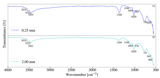
Figure 19.
(a) FT-IR analysis for Mg-Al LDH sample synthesised using milling media size of 2 mm (S2). (b) FT-IR-analysis for Mg-Al LDH sample synthesised using milling media size of 0.25 mm (S9). Milling parameters were set at a rotational speed of 2000 rpm, jacket water inlet temperature of 30 °C, retention time of 1 h and a solids loading of 10%.
3.5. Scanning Electron Microscopy (SEM)
SEM imaging was conducted to provide insight on samples exposed to longer residence times and higher jacket water temperatures. Imaging was conducted at a magnification of 50.00 K with a 200 nm scale and EHT of 1.00 kV for each of the listed samples and are depicted in Figure 20. Samples synthesised at lower jacket water temperatures became increasingly amorphous with an increase in residence time. This was evident through the loss of structure and shape throughout the sample. The formation of minor Platelet-like structures was observed to occur at elevated jacket water temperatures with an increase in retention time. These structures were noted to be similar LDH-like platelets located in literature [11,28].
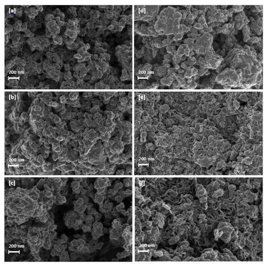
Figure 20.
(a) Mg-Al LDH sample synthesised at a jacket water inlet temperature of 30 °C for 1 h (S4). (b) Mg-Al LDH sample synthesised at a jacket water inlet temperature of 30 °C for 2 h (S5). (c) Mg-Al LDH sample synthesised at a jacket water inlet temperature of 30 °C for 3 h (S6). (d) Mg-Al LDH sample synthesised at a jacket water inlet temperature of 50 °C for 1 h (S10). (e) Mg-Al LDH sample synthesised at a jacket water inlet temperature of 50 °C for 2 h (S11). (f) Mg-Al LDH sample synthesised at a jacket water inlet temperature of 50 °C for 3 h (S12).
4. Discussion
The low solubility’s associated with metallic oxides/hydroxides can make LDH synthesis difficult and can be influenced by factors such as particle size, reaction temperature, residence time, pH and crystallinity [29,37]. All samples exhibited the presence of MgO raw material rather than the expected Mg(OH)2. This indicates that the MgO hydration reaction did not occur readily. MgO reactivity and stability is largely affected by calcination times and temperature [38] and selected conditions could contribute to the absence of Mg(OH)2 observed. XRD patterns depict that Al(OH)3 peaks reduced readily for an increase in rotational speed and residence time at low jacket water temperatures. Comparatively, MgO peaks were still largely present for each sample. An increase in jacket water temperature and residence time resulted in the decrease of both Al(OH)3 and MgO XRD peaks, implying reaction. Subsequently an increase in the formation of LDH occurred. It could be speculated that the reduction in XRD peaks associated with Al(OH)3 were the result of amorphitisation. Reduction of the inert SiO2 peaks further implies that amorphitisation did occur within the system. The grinding of Al(OH)3 could further promote dissolution. Previous studies have indicated that mechanochemical activation of Al(OH)3 has resulted in higher dissolution rates when compared to samples not subject to activation [39]. Similarly, the decrease in particle size in combination with amorphitisation could increase the surface area available for reaction. The use of amorphous Al(OH)3 has previously been found contribute to the formation of high purity Ca-Al LDH [40]. The amorphitisation of Al(OH)3 could therefore be valuable for the formation of LDH within future studies. Elevating the temperature from 30 °C to 50 °C promoted the hydration of MgO to Mg(OH)2. The absence of Mg(OH)2 could further imply that it acts as an intermediate phase for LDH production [11,29]. An increase in system temperature was also expected to improve Al(OH)3 dissolution. Traditional methods involving LDH synthesis from insoluble metallic oxides/hydroxides require long residence times and high reaction temperatures such that the appropriate dissolution conditions are met [29]. The effects associated with elevated temperatures in combination with a change in rotational speed was unclear. This implies that a reaction time of 1 h was insufficient. This was further true for a change in bead size and solids loading. Little information could be deduced after 1 h of milling activity. It was worth noting that increasing the solids loading above 20% would likely prohibit grinding and is therefore not feasible for future studies conducted.
5. Conclusions
The change in milling parameters such as rotational speed, jacket water inlet temperature, solids loading and media size on the synthesis of Mg-Al LDH was investigated. The study served as a continuation of previous work [28], without the addition of a second ageing step. The research was aimed at expanding on the one-step wet mechanochemical synthesis of LDH materials. The synthesis of Mg-Al LDH was successful at elevated jacket water temperatures and increased residence times, with S12 yielding the best result. MgO and Al(OH)3 decreased with an increase in residence time for a jacket water temperature of 50 °C. Longer residence times should be explored to determine the effects on LDH crystallinity, conversion and final particle size. The research could provide insight on the production of crystalline LDH materials for fine particle application. Additional considerations would include the influence of particle size reduction on the dissolution of raw materials and their influence on LDH synthesis. Broad LDH peaks could be attributed to poor crystallinity, the reduction in particle size and the presence of amorphous material. Little to no LDH formation was observed for samples synthesised with a change in rotational speed, despite variation in jacket water temperature. It would be of interest to determine the effects of these parameters with a change in retention time, as 1 h was deemed too short to sufficiently determine the effects of each. Sample viscosity was observed to increase with an increase in solids loading, likely decreasing the motion of the media within the milling chamber. A reduction in media size did result in LDH formation, with incomplete conversion after 1 h of milling. The effect of bead size on the final sample particle size was inconclusive and longer retention times should be explored. It would further be of interest to determine the effect of these changes in milling parameters on the formation and crystallinity of LDH after incorporating a second synthesis step.
Author Contributions
B.A.B.: Methodology, Formal Analysis, Investigation, Data Curation, Writing Original Draft and Final Version, Visualization, Conceptualisation. F.J.W.J.L.: Supervision, Project administration, Funding Acquisition, Writing—Review and Editing, Resources, Conceptualisation, Moral support. All authors have read and agreed to the published version of the manuscript.
Funding
This research was funded by Techsparks (Pty) Ltd and the Technology and Human Resources for Industry Programme (THRIP) administered by the Department of Trade and Industry, South Africa, (grant number THRIP/133/31/03/2016).
Data Availability Statement
Data available in a publicly accessible repository. The data presented in this study are openly available in [Mendley] at [http://dx.doi.org/10.17632/vcwrkgkmm3.1 accessed on 9 March 2021].
Acknowledgments
The authors would like to thank Jeanette Dykstra (X-Ray Fluorescence at the Department of Geology, University of Pretoria (UP), South Africa for analysing all XRF samples within this study. We would further like to thank Wiebke Gröte (X-Ray Diffraction analyst, Department of Geology, University of Pretoria (UP), South Africa) for her efforts analysing XRD data related to this study. Finally, the authors would like to thank the ongoing support of Techsparks (Pty) Ltd.
Conflicts of Interest
The authors declare no conflict of interest. The funders had no role in the design of the study; in the collection, analyses, or interpretation of data; in the writing of the manuscript, or in the decision to publish the results.
References
- Bergaya, F.; Lagaly, G. Handbook of Clay Science, 1st ed.; Elsevier Science & Technology Books: San Diego, CA, USA, 2013; pp. 1021–1069. [Google Scholar]
- Rives, A.V. Layered Double Hydroxides: Present and Future, 1st ed.; Nova Science Publishers: New York, NY, USA, 2001; pp. 8–19. [Google Scholar]
- Qu, J.; Zhang, Q.; Li, X.; He, X.; Song, S. Mechanochemical approaches to synthesize layered double hydroxides: A review. Appl. Clay Sci. 2015, 119, 185–192. [Google Scholar] [CrossRef]
- McCormick, P.G.; Froes, F.H. The fundamentals of mechanochemical processing. JOM 1998, 50, 61–65. [Google Scholar] [CrossRef]
- Ferencz, Z.; Szanados, M.; Adok-Sipiczki, M.; Kukovecz, A.; Konya, Z.; Sipos, P.; Palinko, I. Mechanochemical assisted synthesis of pristine Ca(II)Sn(IV)-layered double hydroxides and their amino acid intercalated composites. Mater. Sci. 2014, 49, 8479–8486. [Google Scholar] [CrossRef]
- Li, Z.; Zhang, Q.; Liu, X.; Chen, M.; Wu, L.; Ai, Z. Mechanochemical synthesis of novel heterostructured Bi2S3/Zn-Al layered double hydroxide nano-particles as efficient visible light reactive Z-scheme photocatalysts. Appl. Surf. Sci. 2018, 452, 123–133. [Google Scholar] [CrossRef]
- Fahami, A.; Beall, G.W.; Enayatpour, S.; Tavangarian, T.; Fahami, M. Rapid preparation of nano hexagonal-shaped hydrocalumite via one-pot mechanochemistry method. Appl. Clay Sci. 2017, 136, 90–95. [Google Scholar] [CrossRef]
- Fahami, A.; Duraia, E.M.; Beall, G.W.; Fahami, M. Facile synthesis and structural insight of chloride intercalated Ca-Al Layered double hydroxide nanopowders. J. Alloys Compd. 2017, 727, 970–977. [Google Scholar] [CrossRef]
- Du, W.; Zheng, L.; Li, X.; Fu, J.; Lu, X.; Hou, Z. Plate like Ni-Mg-Al layered double hydroxides synthesised via a solvent free approach and its application in hydrogenolysis of D sorbitol. Appl. Clay Sci. 2016, 123, 166–172. [Google Scholar] [CrossRef]
- Qu, J.; Li, X.; Lei, Z.; Li, Z.; Chen, M.; Zhang, Q. Mechano-Hydrothermal synthesis of tetraborate pillared Li-Al layered double hydroxide. Am. Ceram. Soc. 2016, 99, 1151–1154. [Google Scholar] [CrossRef]
- Zhang, F.; Du, N.; Song, S.; Liu, J.; Hou, W. Mechano-hydrothermal synthesis of Mg2Al-NO3 layered double hydroxides. Solid State Chem. 2013, 206, 45–50. [Google Scholar] [CrossRef]
- Zhang, F.; Hou, W. Mechano-hydrothermal preparation of Li-Al-OH layered double hydroxides. Sol. State Sci. 2018, 79, 93–98. [Google Scholar] [CrossRef]
- Ferencz, Z.; Kukovecz, A.; Konya, A.; Sipos, P.; Palinko, I. Optimisation of the synthesis parameters of mechanochemically prepared Ca-Al-layered double hydroxide. Appl. Clay Sci. 2015, 112, 94–99. [Google Scholar] [CrossRef]
- Kuramoto, K.; Intasa-ard, S.; Bureekaew, S.; Ogawa, M. Mechanochemical synthesis of finite particles of layered double hydroxide-acetate intercalation compound: Swelling, Thin film ion exchange. Sol. State Chem. 2017, 253, 147. [Google Scholar] [CrossRef]
- Tongamp, W.; Zhang, Q.; Saito, F. Mechanochemical route for synthesizing nitrate form layered double hydroxide. Powder Technol. 2008, 185, 43–48. [Google Scholar] [CrossRef]
- Williams, R.O.; Watts, A.B.; Miller, D.A. Formulating Poorly Water Soluble Drugs, 1st ed.; Springer: New York, NY, USA, 2012; pp. 132–167. [Google Scholar]
- Tongamp, W.; Zhang, Q.; Saito, F. Preparation of meixnerite (Mg–Al–OH) type layered double hydroxide by a mechanochemical route. Mater. Sci. 2007, 42, 9210–9215. [Google Scholar] [CrossRef]
- Li, Z.; Chen, M.; Ai, Z.; Wu, L.; Zhang, Q. Mechanochemical synthesis of CdS/MgAl LDH-precursor as improved visible light driven photocatalyst for organic dye. Appl. Clay Sci. 2018, 163, 265–272. [Google Scholar] [CrossRef]
- Qu, J.; He, X.; Chen, M.; Hu, H.; Zhang, Q.; Liu, X. Mechanochemical synthesis of Cu-Al and methyl orange intercalated Cu-Al layered double hydroxides. Mater. Chem. Phys. 2017, 191, 173–180. [Google Scholar] [CrossRef]
- Qu, J.; He, X.; Chen, M.; Huang, P.; Zhang, Q.; Liu, X. A facile mechanochemical approach to synthesize Zn-Al layered double hydroxide. Solid State Chem. 2017, 250, 1–5. [Google Scholar] [CrossRef]
- Zhong, L.; He, X.; Qu, J.; Li, X.; Lei, Z.; Zhang, Q.; Liu, X. Precursor preparation for Ca-Al layered double hydroxide to remove hexavalent chromium co-existing with calcium and magnesium chloride. Solid State Chem. 2017, 245, 200–206. [Google Scholar] [CrossRef]
- Fahami, A.; Beall, G.W. Mechanosynthesis and characterization of Hydrotalcite like Mg–Al–SO4-LDH. Mater. Lett. 2016, 165, 192–195. [Google Scholar] [CrossRef]
- Qu, J.; Zhong, L.; Li, Z.; Chen, M.; Zhang, Q.; Liu, X. Effect of anion addition on the syntheses of Ca–Al layered double hydroxide via a two-step mechanochemical process. Appl. Clay Sci. 2016, 124, 167–270. [Google Scholar] [CrossRef]
- Szabados, M.; Mészáros, R.; Erdei, S.; Kónya, Z.; Kukovecz, Á.; Sipos, P.; Pálinkó, I. Ultrasonically enhanced mechanochemical synthesis of Ca-Al-layered double hydroxides intercalated by a variety of inorganic anions. Ultrason. Sonochem. 2016, 31, 409–416. [Google Scholar] [CrossRef] [PubMed]
- Szabados, M.; Pásztor, K.; Csendes, Z.; Muráth, S.; Kónya, Z.; Kukovecz, Á.; Carlson, S.; Sipos, P.; Pálinkó, I. Synthesis of high-quality, well-characterised CaAlFe layered triple hydroxide with the combination of dry-milling and ultrasonic irradiation in aqueous solution at elevated temperature. Ultrason. Sonochem. 2016, 32, 173–180. [Google Scholar] [CrossRef] [PubMed]
- Szabados, M.; Varga, G.; Kónya, Z.; Kukovecz, Á.; Carlson, S.; Sipos, P.; Pálinkó, I. Ultrasonically-enhanced preparation, characterization of Ca-Fe-layered double hydroxides with various interlayer halide, azide and oxo anions (CO32-, NO3-, ClO4-). Ultrason. Sonochem. 2018, 40, 853–860. [Google Scholar] [CrossRef]
- Iwasaki, T.; Yoshii, H.; Nakamura, H.; Watano, S. Simple and rapid synthesis of Ni-Fe Layered double hydroxide by a new mechanochemical method. Appl. Clay Sci. 2012, 58, 120–124. [Google Scholar] [CrossRef]
- Barnard, B.A.; Labuschagne, F.J.W.J. Exploring the wet mechanochemical synthesis of Mg-Al, Ca-Al, Zn-Al and Cu-Al layered double hydroxides from oxides, hydroxides and basic carbonates. Crystals 2020, 10, 954. [Google Scholar] [CrossRef]
- Labuschagné, F.J.W.J.; Wiid, A.; Venter, H.P.; Gevers, B.R.; Leuteritz, A. Green synthesis of hydrotalcite from untreated magnesium oxide and aluminum hydroxide. Green Chem. Lett. Rev. 2018, 11, 18–28. [Google Scholar] [CrossRef]
- Agitator Bead Mills for Dispersing and Comminution—Application for Ceramic Processing. Available online: https://d2brmtk65c6t\yc.cloudfront.net/fileadmin/www.netzsch.com/Storage/Press/10_pdf_de.pdf?1422883163 (accessed on 20 January 2021).
- Balaz, P. Mechanochemistry in Nanoscience and Minerals Engineering, 1st ed.; Springer: Heidelberg, Germany, 2008; pp. 117–129. [Google Scholar]
- Ranu, B.; Stolle, A. Ball Milling Towards Green Synthesis: Applications, Projects, Challenges, 1st ed.; The Royal Society of Chemistry: Cambridge, UK, 2015; pp. 241–271. [Google Scholar]
- Labuschagne, F.J.W.J.; Molefe, D.M.; Focke, W.W.; van der Westhuizen, I.; Wright, H.C.; Royeppen, M.D. Heat stabilising flexible PVC with layered double hydroxide derivatives. Polym. Degrad. 2015, 113, 49–54. [Google Scholar] [CrossRef]
- Dubovoy, V.; Subramanyam, R.; Stranick, M.; Du-Thumm, L.; Pan, L. Facile Preparation of Ultrafine Aluminum Hydroxide Particles with or without Mesoporous MCM-41 in Ambient Environments. J. Vis. Exp. 2017, 123, 1–10. [Google Scholar] [CrossRef]
- Socrates, G. Infrared and Raman Characteristic Group Frequencies: Tables and Charts, 1st ed.; John Wiley and Sons: Hoboken, NJ, USA, 2001; pp. 287–295. [Google Scholar]
- Infrared Correlation Chart. Available online: http//ftirsearch.com/ (accessed on 4 December 2019).
- Dyer, J.A.; Scrivner, N.C.; Dentel, S.K. A practical guide for determining the solubility of metal hydroxides and oxides in water. Environ. Prog. 1998, 17, 1–8. [Google Scholar] [CrossRef]
- Ropp, R.C. Encyclopedia of Alkaline Earth Compounds, 1st ed.; Elsevier: Kidlington, UK, 2013; pp. 1–12. [Google Scholar]
- Avvakumov, E.; Mamoru, S.; Kosova, N. Mechanical Activation of Hydrated Oxides. In Soft Mechanochemical Synthesis, 1st ed.; Springer: Boston, MA, USA, 2002; pp. 69–78. [Google Scholar]
- Gevers, B.R.; Labuschagne, F.J.W.J. Green Synthesis of Hydrocalumite (CaAl-OH-LDH) from Ca(OH)2 and Al(OH)3 and the Parameters That Influence Its Formation and Speciation. Crystals 2020, 10, 672. [Google Scholar] [CrossRef]
Publisher’s Note: MDPI stays neutral with regard to jurisdictional claims in published maps and institutional affiliations. |
© 2021 by the authors. Licensee MDPI, Basel, Switzerland. This article is an open access article distributed under the terms and conditions of the Creative Commons Attribution (CC BY) license (http://creativecommons.org/licenses/by/4.0/).