Article

High Hole Mobility Polycrystalline GaSb Thin Films

1
Tyndall National Institute, Dyke Parade, T12 R5CP Cork, Ireland
2
School of Chemistry, University College Cork, T12 YN60 Cork, Ireland
3
Advanced Materials and BioEngineering Research Centre (AMBER), Trinity College Dublin, D02 PN40 Dublin, Ireland
*
Author to whom correspondence should be addressed.
Crystals 2021, 11(11), 1348; https://doi.org/10.3390/cryst11111348
Submission received: 24 September 2021 / Revised: 26 October 2021 / Accepted: 2 November 2021 / Published: 5 November 2021

Abstract

:
In this paper, we report on the structural and electronic properties of polycrystalline gallium antimonide (poly-GaSb) films (50–250 nm) deposited on p+ Si/SiO2 by metalorganic vapour phase epitaxy at 475 °C. GaSb films grown on semi-insulating GaAs substrates are included as comparative samples. In all cases, the unintentionally doped GaSb is p-type, with a hole concentration in the range of 2 × 10¹⁶ to 2 × 1017 cm−3. Exceptional hole mobilities are measured for polycrystalline GaSb on SiO2 in the range of 9–66 cm2/Vs, exceeding the reported values for many other semiconductors grown at low temperatures. A mobility of 9.1 cm2/Vs is recorded for an amorphous GaSb layer in a poly-GaAs/amorphous GaSb heterostructure. Mechanisms limiting the mobility in the GaSb thin films are investigated. It is found that for the GaSb grown directly on GaAs, the mobility is phonon-limited, while the GaSb deposited directly on SiO2 has a Coulomb scattering limited mobility, and the poly-GaAs/amorphous GaSb heterostructure on SiO2 displays a mobility which is consistent with variable-range-hopping. GaSb films grown at low temperatures demonstrate a far greater potential for implementation in p-channel devices than for implementation in ICs.

1. Introduction

Since the invention of the transistor, advancements in its technology have almost exclusively been achieved through dimensional scaling. As progress made through this conventional approach begins to plateau, new pathways must be investigated. Traditional von Neumann architecture involves a separation between the computing and memory components of an integrated circuit (IC) [1]. These components are integrated into a 2D plane and therefore longer bus lengths are required as the number of transistors increases. In turn, this induces greater power losses and latency. Three-dimensional integration has emerged as a promising solution. Here, memory and logic components are interleaved, decreasing the bus lengths required to access off-chip memory while increasing the functionality density and energy efficiency [2,3].
There are two main strategies that can be used to achieve this interleaved structure. The first, often referred to as parallel integration, involves growing the different components on separate wafers before bringing them together to be part of one larger heterostructure. As each component is grown on its own substrate, the growth and doping processes can proceed as normal. The difficulty arises when the components are brought together and mechanical precision must be relied upon for alignment. The process of stacking components can also lead to new defect types in between layers, which must be considered when assessing performance [4]. In contrast, sequential, or monolithic, integration involves each layer being grown on the same substrate, one above the other. This means that rather than relying on mechanical precision to align the layers, the superior accuracy of lithographic precision is now employed [5]. However, this proposed structure is not without its obstacles—namely, the low thermal budget necessary for growth or processing on the upper transistor layers of the structure (normally <500 °C). During conventional processing, dopant activation is often the highest-temperature step [6].
Several studies have reported success in growing materials with high electron mobilities at low temperatures, including metal oxides [7,8,9], metal oxide heterojunctions [10], and 2D materials [11,12,13]. However, if these materials are to be implemented in CMOS architectures, p-type counterparts must be developed. While there are many options for n- and p-type metal oxide semiconductors, p-type semiconductors grown at low temperatures do not exhibit impressive hole mobilities [14]. Organic semiconductors provide some p-type options; however, they, too, do not possess high hole mobilities for a number of reasons [15].
In this study, we investigate low-temperature (<500 °C) grown p-type polycrystalline gallium antimonide (poly-GaSb), a material that does not require intentional doping or dopant activation (thereby allowing us to circumvent this traditionally high-temperature step). The native hole concentration of GaSb is found to originate from Ga vacancies and anti-site defects [16]. Antimony-containing compounds possess the highest bulk mobilities of all III-Vs, and GaSb exhibits a bulk hole mobility double that of silicon. Mobility is one of the most important parameters of a semiconducting material, as it determines how it will perform in a field-effect device. A high mobility allows the device to respond quickly when a field is applied and operate at lower fields without compromising on performance [17]. This would allow for a reduction in the operating voltage, thereby reducing the power dissipation [18]. For CMOS architectures, the dimensions of n- and p-type components are proportional to the n- and p-type mobilities. The n- to p-type mobility ratio of GaSb is low (≈8) compared to that of other materials, making it an attractive candidate for implementation in CMOSs, which make up the majority of IC technology in use today [19]. Polycrystalline GaSb with high hole mobilities has previously been achieved using higher temperatures [20] or III-V substrates [21]. Growing polar GaSb on non-polar SiO2 has traditionally proven difficult [22], but a novel metalorganic vapor phase epitaxy (MOVPE) “droplet epitaxy” method at 475 °C has been shown to work [23].

2. Materials and Methods

Poly-GaSb films (50–250 nm thick) were grown by MOVPE at 475 °C in a commercial horizontal Aixtron 200 reactor using Ga(C2H5)3 and Sb(CH3)3 precursors. For samples where a GaAs buffer layer was added, AsH3 was used as an arsenic source. Growth of the films was achieved using a “droplet epitaxy” approach, whereby III-V precursor droplets on the surface of the substrate were used as crystalline ‘seeds’ for further overgrowth [23]. For each deposition, a Si/SiO2 substrate (oxide thickness 110 nm) was loaded, along with a semi-insulating (SI) GaAs reference substrate. Scanning electron microscopy (SEM) images were taken using an FEI Quanta 650 FEG SEM. Electron dispersive X-ray (EDX) analysis was performed in the SEM chamber using an Oxford Instruments Xmax EDX. Samples were prepared for cross-sectional transmission electron spectroscopy (XTEM) imaging using an FEI Helios NanoLab 600i dual-beam focused ion beam (FIB). Carbon and/or platinum protective layers were deposited before the XTEM was performed using a JEOL JEM-2100. Hall effect measurements were taken on a LakeShore Model 8404 AC/DC Hall effect measurement system, using both (room temperature) RT and closed-circuit refrigeration (CCR) modes. Pieces measuring 1 × 1 cm2 were cut from the center of the sample and the van der Pauw configuration was used for the Hall effect measurements. X-ray diffraction (XRD) analysis was carried out using a Philips Xpert PW3719 diffractometer with Cu Kα radiation.

3. Results

Different nominal thicknesses of poly-GaSb films were investigated with regard to their morphology, actual thickness, and in-plane continuity when grown on SiO2. Figure 1a–c show SEM images of poly-GaSb films of several nominal thicknesses. It is clear from Figure 1a that the nominally 50 nm film is not uniform across the area shown in the image, with some areas appearing to show gaps in the underlying oxide. Both the nominally 150 nm (Figure 1b) and 250 nm (Figure 1c) poly-GaSb films show a similar morphology of a relatively flat layer, followed by nanowire-like growth. For the 150 nm sample, the seemingly continuous level is thinner and appears less uniform than that of the 250 nm sample. Figure 1d shows a 50 nm GaSb film grown on the non-deoxidized SI GaAs reference substrate. This sample shows a much smoother and more uniform film than its counterpart on the Si/SiO2 substrate. To try and replicate these qualities on the SiO2 substrate, a GaAs buffer layer was added to form a GaAs/GaSb heterostructure. It is clear from Figure 1e that this method greatly reduced the roughness and improved the continuity of the 50 nm GaSb film when grown on Si/SiO2 (AFM results from the 50 nm GaSb films with and without a GaAs layer on SiO2 are shown in Figure S1). This was also true for the reference SI GaAs substrate, as shown in Figure 1f.
Room temperature Hall effect measurements were obtained (Table 1), with the nominally 250 nm GaSb film returning an impressive hole mobility figure of 66.5 cm2/Vs, which far exceeds the reported values for metal oxide semiconductors [14,24,25] and 2D materials [26,27] grown at <500 °C on amorphous substrates. There was no significant difference between the hole mobility results for the 50 nm and 150 nm films (24.2 and 22.9 cm2/Vs respectively), suggesting that complete film continuity was achieved somewhere between the nominal 150 and 250 nm thicknesses. Table 2 shows the results for films grown on GaAs substrates. Mobility increased with thickness, without the sudden increase between 150 and 250 nm films that was evident for the films grown on SiO2, and which was taken as an indication of the onset of film continuity. The carrier concentration results for the films listed in Table 1 and Table 2 were relatively similar for all of the films, apart from the 50 nm GaSb on SiO2, which had a carrier concentration at least an order of magnitude lower than that of the other films whose results are presented here. For device applications, thinner and smoother films are preferable. While the addition of a GaAs buffer layer resulted in significant morphological improvements for the 50 nm GaSb film on Si/SiO2, the hole mobility reduced to 9.1 cm2/Vs (compared to 24.2 cm2/Vs for the same film grown directly on Si/SiO2 without the 50 nm GaAs buffer layer). The same heterostructure implemented on a GaAs substrate had the opposite effect on mobility, which increased from 76.8 to 218.57 cm2/Vs.
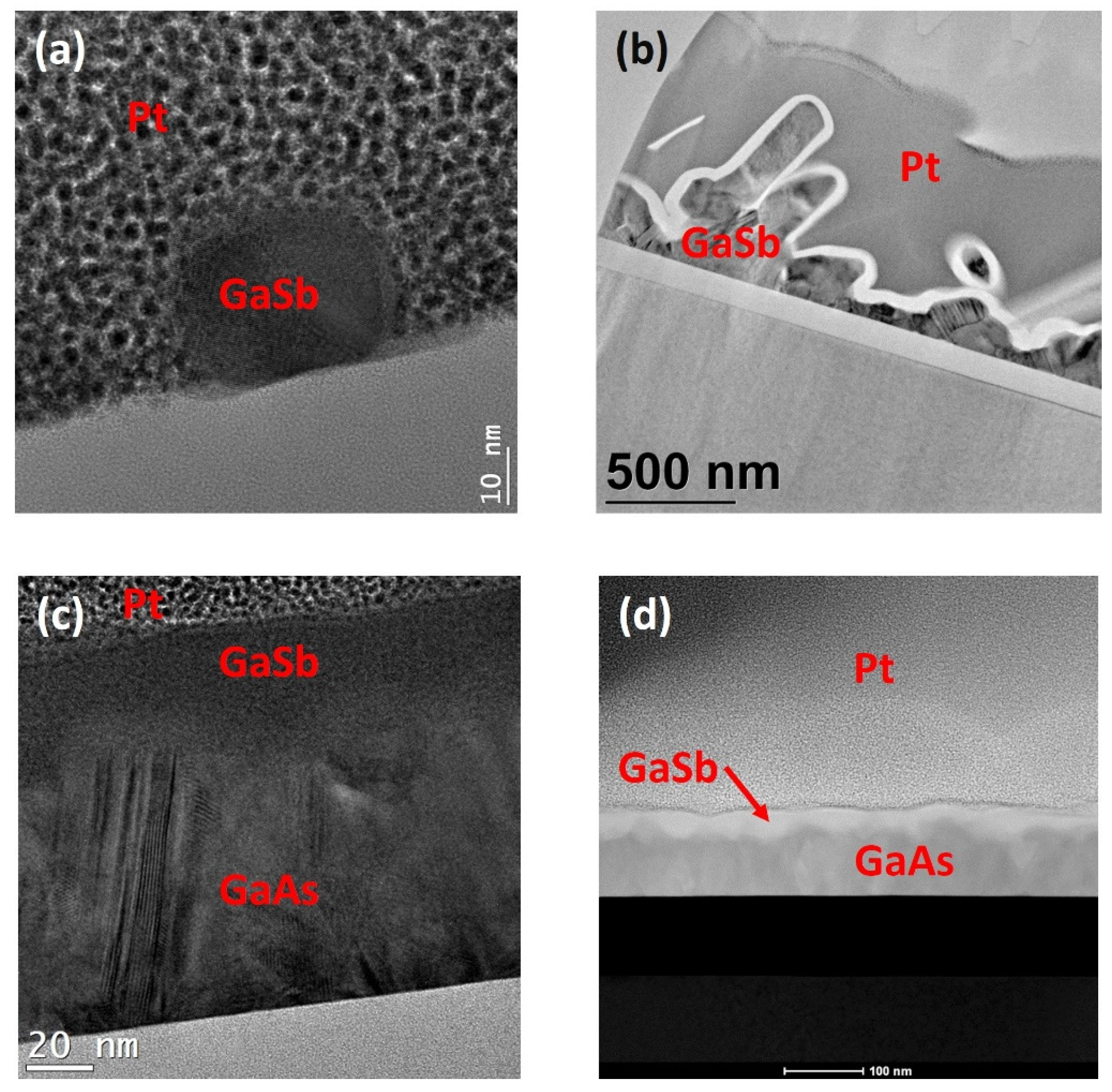
To investigate this surprising result from the 50 nm GaAs + 50 nm GaSb sample and to gain further knowledge of the actual thickness and structure of other films, XTEM was performed. Figure 2a shows a representative area of the nominally 50 nm sample. XTEM confirmed the polycrystalline nature of the GaSb present on the substrate; however, there was a lack of uniformity over the area of the lamella in the image. Taking the Hall mobility results into account (Table 1), it is reasonable to assume that there are 3D percolation paths present in this film, allowing for carrier transport. The 250 nm GaSb film (Figure 2b) was also confirmed to be polycrystalline. From the cross-section, the continuous layer seen in the SEM images is also evident, along with a nanowire-like growth.
Interestingly, while the initial nominally 50 nm GaAs buffer layer displayed in Figure 2c shows a polycrystalline structure, the subsequent nominally 50 nm GaSb does not, and in fact appears to be amorphous. This would explain the drop in the mobility between the film without the GaAs buffer layer and the film with the GaAs buffer layer. The scanning transmission electron microscopy (STEM) image (Figure 2d) gives a wider view of the overall topography of the two layers. The GaAs layer has a saw-tooth shape consistent with {111} facets [28], while the amorphous GaSb layer fills in the facets and has an overall smoothing effect. EDX was used to confirm that the elemental make-up of the layers was as expected (resulting in the spectra shown in Figure S2).
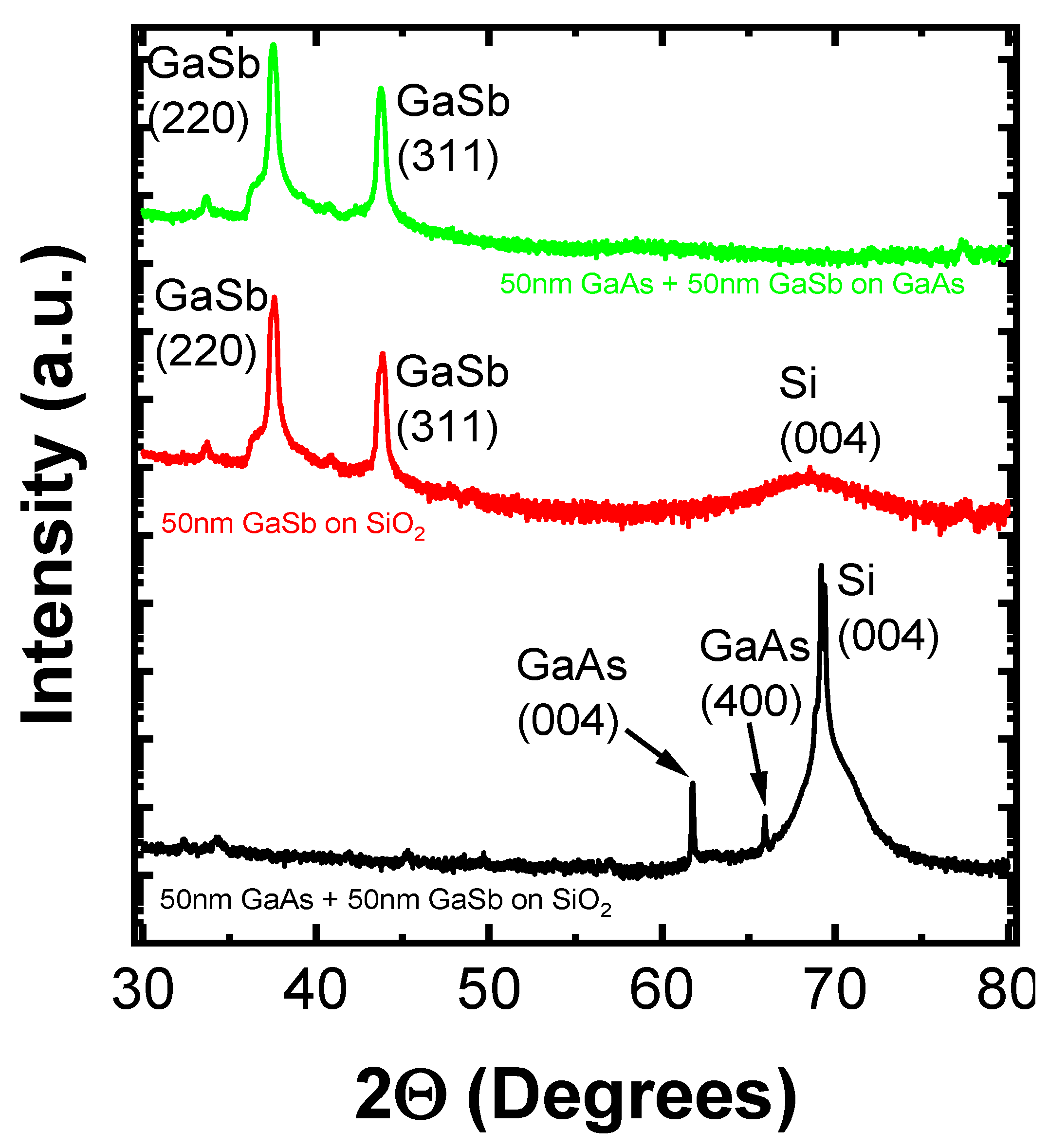
To determine if the GaSb grew in an amorphous form and to rule out amorphization during the preparation for XTEM using the FIB, an XRD analysis was performed on a part of the sample which had not gone through the preparation on the FIB. Figure 3 shows the resulting spectrum. The GaAs reflections were intense and indicate a polycrystalline layer with regions of good-quality crystalline GaAs. Several weak peaks could be identified for GaSb, suggesting that it may have contained very small regions with some level of crystallinity, but that its dominant phase was amorphous. In comparison, the 50 nm GaSb on SiO2 and 50 nm GaAs + 50 nm GaSb on SI GaAs both showed strong peaks for the crystalline GaSb phases and so were not amorphous.
To understand the mechanisms and limitations of the hole mobility of poly-GaSb films, temperature-dependent Hall effect measurements were performed. It is clear from Figure 4a,b that the dominant scattering mechanism limiting the mobility was different for the 250 nm GaSb grown directly on the SI GaAs substrate than for the 250 nm grown directly on the Si/SiO2 substrate. For the GaSb grown directly on the SI GaAs substrate (Figure 4a), mobility decreased as the carrier concentration and temperature increased. This observation is consistent with phonon scattering [29]. For the GaSb grown directly on the Si/SiO2 substrate (Figure 4b) and for the 50 nm GaAs + 50 nm GaSb grown on the Si/SiO2 heterostructure (Figure 4c), both the carrier mobility and the concentration increased as the temperature increased. This could be a result of thermionic emission over grain boundary potential barriers [30] or Coulombic scattering [31].
Further analysis was performed on the temperature-dependent results of the 250 nm GaSb on Si/SiO2 and the 50 nm GaAs + 50nm GaSb on Si/SiO2, where the exact mechanism limiting the mobility was not immediately obvious. The 250 nm GaSb on the SiO2 sample shows an initially linear region and then begins to turn over at higher temperatures, transitioning into another region with a different limiting mechanism. The following equation shows the temperature dependence of the Coulombic scattering limited mobility:
μ d i s l = 30   ·   2 π   ·   ε 2   · a 2   ·   ( k T ) 3 / 2 N d i s l   ·   e 3   ·   f 2   ·   λ D   ·   m
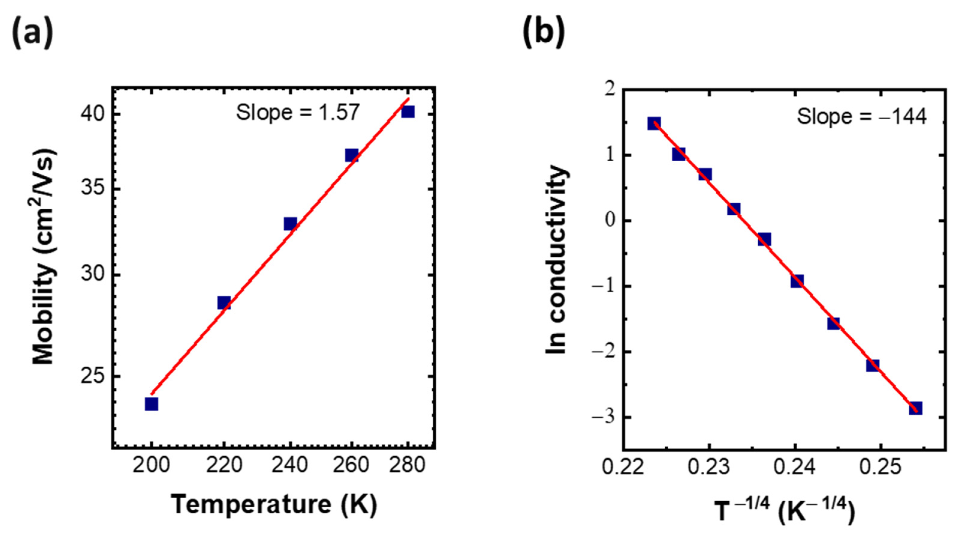
where ε is the dielectric constant, a is the distance between centers, T is the temperature, Ndisl is the concentration of dislocations, e is the elementary charge, f is the occupation rate of the centers, and λD is the Debye screening length [32]. From this equation, we can see that the Coulombic scattering limited mobility should increase with a slope of 3/2 as the temperature increases on a log–log scale. This is close to the experimental value of 1.57 which was observed for the 250 nm GaSb on a Si/SiO2 substrate between 200 K and 280 K, Figure 5a. The observation that the mobility begins to turn over in Figure 4b and tend towards a negative slope as the temperature continues to increase is consistent with observations from previous studies [31]. This transition is due to the mobility becoming phonon-scattering-limited at higher temperatures.
Figure 5b shows the natural log of the conductivity obtained from the Hall effect measurements on the amorphous GaSb with the GaAs buffer layer plotted against T−1/4. This results in a linear plot, which is consistent with 3D variable-range-hopping limited mobility. Mott’s Law [33] shows the following relationship:
l n σ = A ( T 0 T ) 1 / 4  
From this equation, we can see that the slope of the ln conductivity vs. T−1/4 graph should be equal to T01/4. This yields a value for T0 of 4.3 × 10⁸ K, which is similar to previously reported values for amorphous Germanium [34] and poly-Si [35]. T0 is defined as:
T 0 = β k B   · g ( μ ) ·   a 3  
where β is a numerical coefficient, g(µ) is the density of states at the Fermi level, and a is the localization of the states near the Fermi level [36]. Variable-range-hopping occurs when the temperature is low enough for the resistances between neighboring states to become greater than those between faraway states, which exist in a narrow energy band near the Fermi level. As the temperature decreases, the average hopping-distance increases with T−1/4 [36].

4. Discussion

We investigated high hole mobility polycrystalline (66.5 cm2/Vs) and amorphous (9.1 cm2/Vs) GaSb grown on amorphous substrates. The hole mobility of 9.1 cm2/Vs obtained for the amorphous GaSb layer as part of a GaAs/GaSb heterostructure exceeds previously reported hole mobilities for amorphous semiconductors on amorphous substrates [37,38,39]. Factors limiting the hole mobility in the GaSb films were investigated through temperature-dependent Hall effect measurements. The dominant limiting factor was found to vary depending on the substrate and the presence/absence of a GaAs buffer layer. For the GaSb deposited directly onto GaAs, the mobility was phonon-limited, the GaSb grown directly on SiO2 had a Coulomb scattering limited mobility, and the amorphous GaSb film with a GaAs buffer layer on SiO2 displayed a mobility that was variable-range-hopping limited. Both the polycrystalline and the amorphous GaSb films studied in this paper show promising potential as high hole mobility semiconductor materials grown below 500 °C, compatible with back-end-of-line integration.

Supplementary Materials

The following are available online at https://www.mdpi.com/article/10.3390/cryst11111348/s1: Figure S1. AFM results for (a,b) 50 nm GaSb on SiO2, and (c,d) 50 nm GaAs + 50 nm GaSb on SiO2. Figure S2. EDX of cross-sectional lamella taken from heterostructure of 50 nm GaAs + 50 nm GaSb on SiO2.

Author Contributions

A.C.: preparation of manuscript, methodology, investigation, data analysis; F.G.: conceptualization, formal analysis, supervision, reviewing and editing manuscript; A.G.: growth of materials, methodology; E.M.: methodology; R.E.N.: SEM imaging; M.S.: TEM analysis; B.S.: TEM analysis; E.P.: conceptualization; C.O.: XRD analysis, reviewing and editing manuscript, supervision; P.K.H.: conceptualization, funding acquisition, reviewing and editing manuscript, supervision, methodology. All authors have read and agreed to the published version of the manuscript.

Funding

The authors wish to acknowledge the Irish Research Council (EPSPG/2017/356) and the AMBER 2 project (12/RC/2278_P2) for their financial support of this work.

Data Availability Statement

The data that support the findings of this study are available from the corresponding author upon reasonable request.

Acknowledgments

We appreciate the assistance of the staff in the Advanced Microscopy Laboratory (AML) in CRANN in obtaining figures for this paper.

Conflicts of Interest

The authors declare no conflict of interest.

References

  1. von Neumann, J. First draft of a report on the EDVAC. IEEE Ann. Hist. Comput. 1993, 15, 27–75. [Google Scholar] [CrossRef]
  2. Datta, S.; Dutta, S.; Grisafe, B.; Smith, J.; Srinivasa, S.; Ye, H. Back-End-of-Line Compatible Transistors for Monolithic 3-D Integration. IEEE Micro 2019, 39, 8–15. [Google Scholar] [CrossRef]
  3. Wong, H.-S.P.; Salahuddin, S. Memory leads the way to better computing. Nat. Nanotechnol. 2015, 10, 191–194. [Google Scholar] [CrossRef] [Green Version]
  4. Lee, H.-H.S.; Chakrabarty, K. Test Challenges for 3D Integrated Circuits. IEEE Des. Test Comput. 2009, 26, 26–35. [Google Scholar] [CrossRef] [Green Version]
  5. Shulaker, M.M.; Wu, T.F.; Sabry, M.M.; Wei, H.; Wong, H.-P.; Mitra, S. Monolithic 3D integration: A path from concept to reality. In Proceedings of the 2015 Design, Automation & Test in Europe Conference & Exhibition (DATE), Grenoble, France, 9–13 March 2015; pp. 1197–1202. [Google Scholar]
  6. Wolf, S.; Tauber, R. Process Technology. In Silicon Processing for the VLSI ERA, 2nd ed.; Lattice Press: Sunset Beach, CA, USA, 2000; Volume 1, pp. 12–13. [Google Scholar]
  7. Esro, M.; Vourlias, G.; Somerton, C.; Milne, W.I.; Adamopoulos, G. High-Mobility ZnO Thin Film Transistors Based on Solution-processed Hafnium Oxide Gate Dielectrics. Adv. Funct. Mater. 2015, 25, 134–141. [Google Scholar] [CrossRef]
  8. Shih, C.W.; Chin, A.; Lu, C.-F.; Su, W.-F. Remarkably high mobility ultra-thin-film metal-oxide transistor with strongly overlapped orbitals. Sci. Rep. 2016, 6, srep19023. [Google Scholar] [CrossRef] [PubMed] [Green Version]
  9. Gaspar, D.; Pereira, L.; Gehrke, K.; Galler, B.; Fortunato, E.; Martins, R. High mobility hydrogenated zinc oxide thin films. Sol. Energy Mater. Sol. Cells 2017, 163, 255–262. [Google Scholar] [CrossRef]
  10. Faber, H.; Das, S.; Lin, Y.-H.; Pliatsikas, N.; Zhao, K.; Kehagias, T.; Dimitrakopulos, G.; Amassian, A.; Patsalas, P.A.; Anthopoulos, T.D. Heterojunction oxide thin-film transistors with unprecedented electron mobility grown from solution. Sci. Adv. 2017, 3, e1602640. [Google Scholar] [CrossRef] [Green Version]
  11. Zheng, J.; Yan, X.; Lu, Z.; Qiu, H.; Xu, G.; Zhou, X.; Wang, P.; Pan, X.; Liu, K.; Jiao, L. High-Mobility Multilayered MoS2 Flakes with Low Contact Resistance Grown by Chemical Vapor Deposition. Adv. Mater. 2017, 29. [Google Scholar] [CrossRef]
  12. Yang, R.; Li, H.; Smithe, K.K.H.; Kim, T.R.; Okabe, K.; Pop, E.; Fan, J.A.; Wong, H.-S.P. 2D molybdenum disulfide (MoS2) transistors driving RRAMs with 1T1R configuration. In Proceedings of the 2017 IEEE International Electron Devices Meeting (IEDM), San Francisco, CA, USA, 2–6 December 2017; pp. 19.5.1–19.5.4. [Google Scholar]
  13. Wu, J.; Tan, C.; Tan, Z.; Liu, Y.; Yin, J.; Dang, W.; Wang, M.; Peng, H. Controlled Synthesis of High-Mobility Atomically Thin Bismuth Oxyselenide Crystals. Nano Lett. 2017, 17, 3021–3026. [Google Scholar] [CrossRef]
  14. Wang, Z.; Nayak, P.K.; Caraveo-Frescas, J.A.; Alshareef, H.N. Recent Developments in p-Type Oxide Semiconductor Materials and Devices. Adv. Mater. 2016, 28, 3831–3892. [Google Scholar] [CrossRef] [Green Version]
  15. Atahan-Evrenk, Ş.; Aspuru-Guzik, A. Prediction and Theoretical Characterization of p-Type Organic Semiconductor Crystals for Field-Effect Transistor Applications. In Prediction and Calculation of Crystal Structures: Methods and Applications; Springer International Publishing: Manhattan, NY, USA, 2014; pp. 95–138. [Google Scholar]
  16. Dutta, P.S.; Bhat, H.L.; Kumar, V. The physics and technology of gallium antimonide: An emerging optoelectronic material. J. Appl. Phys. 1997, 81, 5821–5870. [Google Scholar] [CrossRef]
  17. Myronov, M. Chapter 3—Molecular Beam Epitaxy of High Mobility Silicon, Silicon Germanium and Germanium Quantum Well Heterostructures. In Molecular Beam Epitaxy, 2nd ed.; Elsevier: Amsterdam, The Netherlands, 2018; pp. 37–54. [Google Scholar]
  18. Alamo, J.A.D. Nanometre-scale electronics with III–V compound semiconductors. Nature 2011, 479, 317–323. [Google Scholar] [CrossRef]
  19. Nainani, A.; Irisawa, T.; Yuan, Z.; Bennett, B.R.; Boos, J.B.; Nishi, Y.; Saraswat, K.C. Optimization of the Al2O3/GaSb Interface and a High-Mobility GaSb pMOSFET. IEEE Trans. Electron. Devices 2011, 58, 3407–3415. [Google Scholar] [CrossRef]
  20. Zaixiang, Q.; Yun, S.; Weiyu, H.; Qing, H.; Changjian, L. Polycrystalline GaSb thin films grown by co-evaporation. J. Semicond. 2009, 30. [Google Scholar] [CrossRef]
  21. Dong, Y.; Scott, D.W.; Wei, Y.; Gossard, A.C.; Rodwell, M.J. Low-resistance p-type polycrystalline GaSb grown by molecular beam epitaxy. J. Cryst. Growth 2003, 256, 223–229. [Google Scholar] [CrossRef]
  22. Ha, M.T.H.; Huynh, S.H.; Do, H.B.; Nguyen, T.A.; Luc, Q.H.; Lee, C.T.; Chang, E.Y. Entirely relaxed lattice-mismatched GaSb/GaAs/Si(001) heterostructure grown via metalorganic chemical vapor deposition. Appl. Phys. Express 2018, 11, 051202. [Google Scholar] [CrossRef]
  23. Gocalinska, A.; Pescaglini, A.; Secco, E.; Mura, E.E.; Thomas, K.; Curran, A.; Gity, F.; Nagle, R.; Schmidt, M.; Michałowski, P.P.; et al. Next generation low temperature polycrystalline materials for above IC electronics. High mobility n- and p-type III–V metalorganic vapour phase epitaxy thin films on amorphous substrates. J. Phys. Photonics 2020, 2, 025003. [Google Scholar] [CrossRef]
  24. Bai, S.; Cao, M.; Jin, Y.; Dai, X.; Liang, X.; Ye, Z.; Li, M.; Cheng, J.; Xiao, X.; Wu, Z.; et al. Low-Temperature Combustion-Synthesized Nickel Oxide Thin Films as Hole-Transport Interlayers for Solution-Processed Optoelectronic Devices. Adv. Energy Mater. 2014, 4, 1301460. [Google Scholar] [CrossRef]
  25. Shih, C.W.; Chin, A.; Lu, C.-F.; Su, W.-F. Remarkably High Hole Mobility Metal-Oxide Thin-Film Transistors. Sci. Rep. 2018, 8, 1–6. [Google Scholar] [CrossRef] [Green Version]
  26. Saji, K.J.; Tian, K.; Snure, M.; Tiwari, A. 2D Tin Monoxide—An Unexplored p-Type van der Waals Semiconductor: Material Characteristics and Field Effect Transistors. Adv. Electron. Mater. 2016, 2, 1500453. [Google Scholar] [CrossRef]
  27. Vandalon, V.; Verheijen, M.A.; Kessels, W.M.M.; Bol, A.A. Atomic Layer Deposition of Al-Doped MoS2: Synthesizing a p-type 2D Semiconductor with Tunable Carrier Density. ACS Appl. Nano Mater. 2020, 3, 10200–10208. [Google Scholar] [CrossRef]
  28. Minari, F.; Billia, B. Mixed cells in directional solidification of In-doped GaAs; cellular profile and shape-induced stresses. J. Cryst. Growth 1994, 140, 264–276. [Google Scholar] [CrossRef]
  29. Nakashima, K. Electrical and Optical Studies in Gallium Antimonide. Jpn. J. Appl. Phys. 1981, 20, 1085–1094. [Google Scholar] [CrossRef]
  30. Seto, J.Y.W. The electrical properties of polycrystalline silicon films. J. Appl. Phys. 1975, 46, 5247–5254. [Google Scholar] [CrossRef]
  31. Ng, H.M.; Doppalapudi, D.; Moustakas, T.D.; Weimann, N.; Eastman, L.F. The role of dislocation scattering in n-type GaN films. Appl. Phys. Lett. 1998, 73, 821–823. [Google Scholar] [CrossRef]
  32. Pödör, B. Electron Mobility in Plastically Deformed Germanium. Phys. Status Solidi B 1966, 16, K167–K170. [Google Scholar] [CrossRef]
  33. Mott, N.F. Conduction in non-crystalline materials. Philos. Mag. A J. Theor. Exp. Appl. Phys. 1969, 19, 835–852. [Google Scholar] [CrossRef]
  34. Lewis, A.J. Conductivity and thermoelectric power of amorphous germanium and amorphous silicon. Phys. Rev. B 1976, 13, 2565–2575. [Google Scholar] [CrossRef]
  35. Scheller, L.-P.; Nickel, N.H. Charge transport in polycrystalline silicon thin-films on glass substrates. J. Appl. Phys. 2012, 112, 013713. [Google Scholar] [CrossRef]
  36. Shklovskii, B.I.; Efros, A.L. Variable-Range Hopping Conduction. In Electronic Properties of Doped Semiconductors; Springer: Berlin/Heidelberg, Germany, 1984; pp. 202–227. [Google Scholar]
  37. Liu, A.; Zhu, H.; Park, W.-T.; Kang, S.-J.; Xu, Y.; Kim, M.-G.; Noh, Y.-Y. Room-Temperature Solution-Synthesized p-Type Copper(I) Iodide Semiconductors for Transparent Thin-Film Transistors and Complementary Electronics. Adv. Mater. 2018, 30, e1802379. [Google Scholar] [CrossRef]
  38. Xu, W.; Zhang, J.; Li, Y.; Zhang, L.; Chen, L.; Zhu, D.; Cao, P.; Liu, W.; Han, S.; Liu, X.; et al. p-Type transparent amorphous oxide thin-film transistors using low-temperature solution-processed nickel oxide. J. Alloys Compd. 2019, 806, 40–51. [Google Scholar] [CrossRef]
  39. Jun, T.; Kim, J.; Sasase, M.; Hosono, H. Material Design of p-Type Transparent Amorphous Semiconductor, Cu–Sn–I. Adv. Mater. 2018, 30, 1706573. [Google Scholar] [CrossRef] [PubMed]
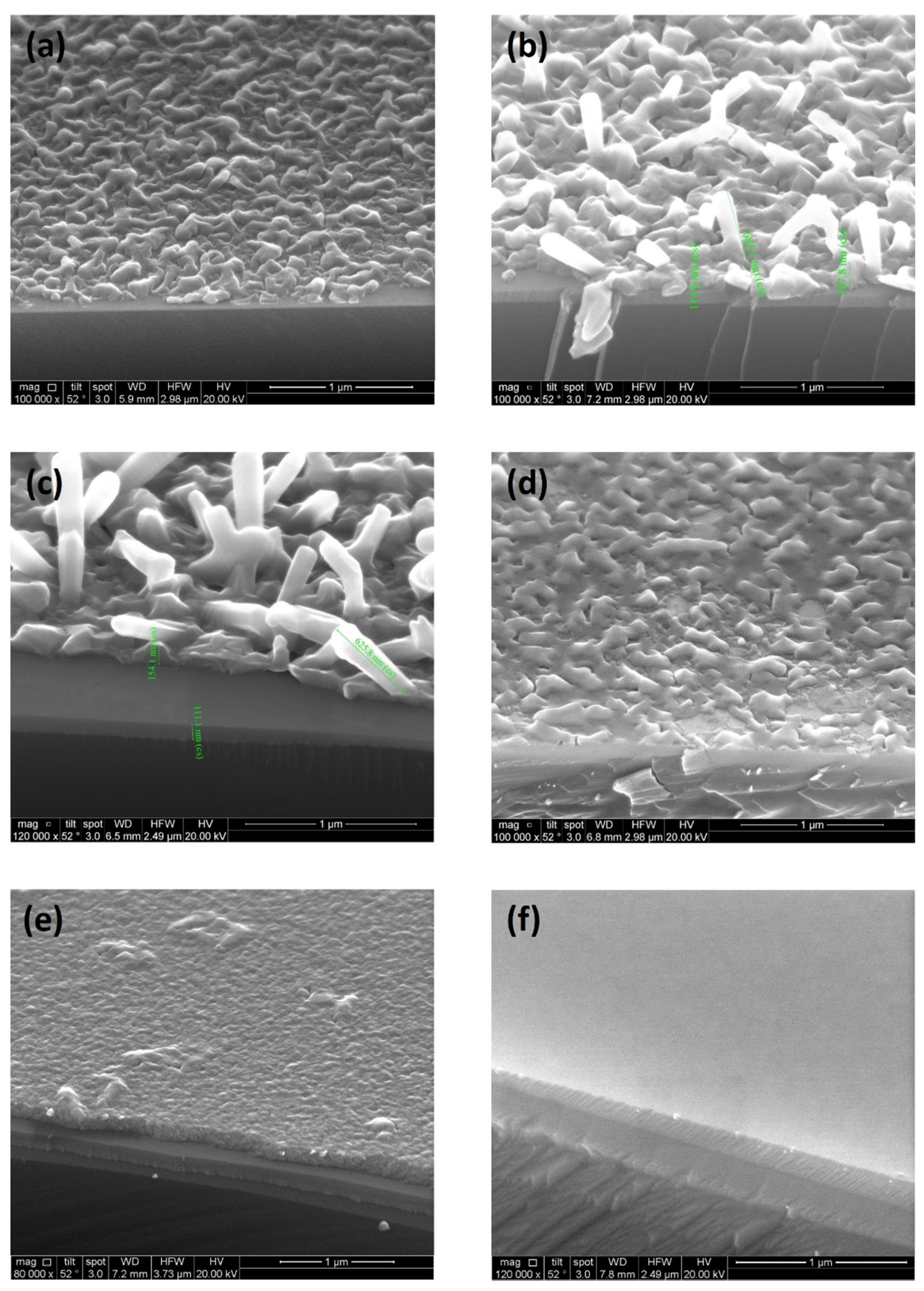
Figure 1. SEM images: (a) 50 nm GaSb on SiO2, (b) 150 nm GaSb on SiO2, (c) 250 nm GaSb on SiO2, (d) 50 nm GaSb on SI GaAs, (e) 50 nm GaAs + 50 nm GaSb on SiO2, and (f) 50 nm GaAs + 50 nm GaSb on SI GaAs. All scale bars are 1 µm.
Crystals 11 01348 g001
Figure 2. XTEM images of (a) 50 nm GaSb on SiO2, (b) 250 nm GaSb on SiO2, and (c) 50 nm GaAs + 50 nm GaSb on SiO2. (d) STEM of 50 nm GaAs + 50 nm GaSb on SiO2.
Crystals 11 01348 g002
Figure 3. XRD of 50 nm GaAs + 50 nm GaSb on SiO2, 50 nm GaSb on SiO2, and 50 nm GaAs + 50 nm GaSb on GaAs.
Crystals 11 01348 g003
Figure 4. Carrier mobility and concentration of (a) 250 nm GaSb on a SI GaAs substrate, (b) 250 nm GaSb on a Si/SiO2 substrate, and (c) 50 nm GaAs + 50 nm GaSb on a Si/SiO2 substrate.
Crystals 11 01348 g004
Figure 5. (a) log–log plot of hole mobility vs. temperature for 250 nm GaSb on SiO2 over temperature range of 200–280 K, and (b) plot of ln conductivity vs. T−1/4 for 50 nm GaAs + 50 nm GaSb on SiO2.
Crystals 11 01348 g005
Table 1. Room temperature Hall effect measurement results for poly-GaSb films grown on SiO2 at 475 °C.
250 nm GaSb on SiO2150 nm GaSb on SiO250 nm GaSb on SiO250 nm GaAs + 50 nm GaSb on SiO2
Hall Mobility
(cm2/V·s)
66.522.924.29.1
Carrier Typepppp
Sheet carrier conc. (cm−2)4.6 × 10123.26 × 10129.92 × 10101.65 × 1012
Carrier conc
(cm−3)
1.84 × 10172.17 × 10171.98 × 10161.37 × 1017
Table 2. Room temperature Hall effect measurement results for poly-GaSb films grown on GaAs at 475 °C.
250 nm GaSb on GaAs150 nm GaSb on GaAs50 nm GaSb on GaAs50 nm GaAs + 50 nm GaSb on GaAs
Hall Mobility
(cm2/V·s)
293.217276.8218.57
Carrier Typepppp
Sheet carrier conc. (cm−2)2.92 × 10125.92 × 10124.27 × 10121.65 × 1012
Carrier conc.
(cm−3)
1.17 × 10173.9 × 10178.54 × 10173.3 × 1017
Publisher’s Note: MDPI stays neutral with regard to jurisdictional claims in published maps and institutional affiliations.